

humiFog - UA
Pressure Atomizing Multi-Point
Zone Control Panel
User manual
READ AND SAVE
THESE INSTRUCTIONS

We wish to save you time and money!
We can assure you that the thorough reading of this manual will guarantee correct
installation and safe use of the product described
WARNINGS
BEFORE INSTALLING OR HANDLING THE HUMIDIFIER PLEASE CAREFULLY READ AND FOLLOW THE INSTRUCTIONS AND
SAFETY STANDARDS DESCRIBED IN THIS MANUAL AND ON THE LABELS ATTACHED TO THE humiFog.
CAUTION: ALWAYS DISCONNECT THE MAIN POWER BEFORE OPENING OR SERVICING THE HUMIDIFIER!
This appliance has been designed exclusively to directly humidify in ducts and AHUs through the atomizing rack.
The quality of the water used affects the operation of this unit, so the humiFog must be supplied with treated water (Reverse
Osmosis or Deionized). The installation, use, and maintenance operations must be carried out according to the instructions
contained in this manual and on the labels applied internally and externally.
IMPORTANT: BEFORE beginning installation:
Check for shipping damage to carton. Mark the shipping waybill accordingly.
Open cartons and check for any hidden damage. Mark the shipping waybill accordingly.
Check packing slip to ensure all items have been received. Notify CAREL of any shortages or damaged parts. You must
notify CAREL within 5 working days of any shortages.
The conditions of the environment and the power supply voltage must comply with the specified values listed on the data
label in the humidifier.
All other uses and modifications made to the humidifier that are not authorized by the manufacturer are considered
incorrect, and the manufacturer assumes no liability for the consequences of any such unauthorized use.
Please note that the humidifier contains powered electrical devices and high pressure components.
All service and/or maintenance operations must be performed by qualified personnel who are aware of the necessary
precautions and are capable of performing the operations correctly.
Disconnect the humidifier from the main power supply before accessing any internal parts.
The humidifier must be installed in accordance with all local and national standards.
WARNING: Your humidifier requires water to operate. Do NOT mount it above materials or machinery that could be
damaged if a leak occurs. CAREL assumes no responsibility for consequential or inconsequential damage as a result of any
leaks.
Disposal of the parts of the humidifier: The humidifier is made up of metallic and plastic parts. All parts must be disposed of
according to the local standards on waste disposal.
Warranty on materials: 2 years (from the date of production, excluding the consumable parts).
Page 2 of 38

TABLE OF CONTENTS
1. HOW THE humiFog WORKS ................................................................................................................. 4
2. COMPONENTS ....................................................................................................................................... 5
2.1 Main pumping station ........................................................................................................................................ 5
2.2 Microprocessor control system ....................................................................................................................... 5
2.3 Atomizing nozzles .............................................................................................................................................. 6
2.4 Distribution ......................................................................................................................................................... 6
2.5 Zone Control Panels .......................................................................................................................................... 6
2.6 Zone Control PaneL Dimensions and weights ................................................................................................ 7
2.7 zone control cabinet components .................................................................................................................... 8
3. MODELS ................................................................................................................................................ 8
3.1 Zone Control PANEL CODING GUIDE .............................................................................................................. 8
4. ZONE CONTROL CABINET POSITIONING AND MOUNTING ................................................................ 9
4.1 Zone Control Positioning and Mounting NOTES ............................................................................................. 9
4.2 Zone Control PANEL CLEARANCES ................................................................................................................ 9
4.3 Zone Control drilling template ........................................................................................................................ 10
5. ELECTRICAL WIRING ........................................................................................................................... 10
5.1 Wiring Connection Layouts (UAZN***108) ..................................................................................................... 10
5.2 Wiring Connection Layouts (UAZN***109) ..................................................................................................... 11
5.3 DETAILS OF (2) AND (3) TERMINAL BLOCKS (UAZN***108) ....................................................................... 12
5.4 DETAILS OF (2)(TBS1) AND (3)(TBS3,TBS4) TERMINAL BLOCKS (UAZN***109) ...................................... 12
5.5 Electrical Wiring ............................................................................................................................................... 13
5.6 Control signals from external voltage-free contact (humidistat)(UAZN***108) ................................................. 14
5.7 Modulating control signal(UAZN***108) ......................................................................................................... 15
5.8 control signal Wiring (UAZN***109) ................................................................................................................ 16
5.9 Solenoid Valve connection For Distribution System (UAZN***108) ............................................................. 17
5.10 Solenoid Valve connection For Distribution System (UAZN**109) .............................................................. 18
5.11 Cumulative alarm relay (J15) .............................................................................................................................. 19
5.12 Inputs from external devices .............................................................................................................................. 19
5.13 Supervisor Network ......................................................................................................................................... 19
5.14 Pumping Station to Multi Zones ..................................................................................................................... 20
5.15 Duplex Control Wiring / Multiple zones per Air HandleR .............................................................................. 21
6. START-UP ............................................................................................................................................ 22
6.1 Startup Checklist.............................................................................................................................................. 22
6.2 Re-addressing the Controllers and Displays for Multi-zone or Duplex Systems ....................................... 22
6.3 Re-addressing PCO3 controller ...................................................................................................................... 23
6.4 Re-addressing PGD display ............................................................................................................................ 23
7. THE humiFog CONTROLLER ............................................................................................................... 24
7.1 MULTI-ZONE IN SINGLE ahu SETUP OVERVIEW .......................................................................................... 25
7.2 SYSTEM STATUS ............................................................................................................................................. 25
7.3 Main Menu ........................................................................................................................................................ 26
7.4 Service menu .................................................................................................................................................... 28
7.4.1 Service Settings Submenu ............................................................................................................................................................ 29
7.4.2 Manual Management Submenu ................................................................................................................................................... 30
7.5 Manufacturer Submenu ................................................................................................................................... 30
8. REPLACEMENT PARTS ........................................................................................................................ 32
8.1 See specific material list(s) provided with unit. ............................................................................................ 32
9. WIRING DIAGRAM .............................................................................................................................. 33
10. WARRANTY ......................................................................................................................................... 37
Page 3 of 38

A
A
1. HOW THE humiFog WORKS
The humiFog humidification system is a high pressure atomizing system designed to produce a fine mist that readily
evaporates to raise the relative humidity. The atomizing humidifier is an efficient humidification system that is especially
suitable for larger installations, where high flow-rates of water are required without the necessity of excessive energy
expenditure. When the humidity value in the environment is less then the desired value, as measured by a probe or external
controller, the controller starts the volumetric piston pump, which sends the “treated” water to the nozzles.
The treated water; using a reverse osmosis or deionizer system, is pumped at a pressure of 1000psi (75bar) and sent via the
connection pipes to the atomizing nozzles. The nozzles then reduce the jet of water into a multitude of very fine water
droplets (10-20 microns). Because of the fine droplet size, the water can then easily change its state and vaporize. The energy
required for this transformation is supplied by the ambient air; at a rate of 690 W per liter/hour. Consequently, there is a
decrease in temperature in the environment being humidified, and this process may be useful in many applications (adiabatic
transformation).
The humiFog unit must be supplied with treated water, for the following reasons:
To reduce the introduction into the environment of dust due to the mineral salts found in the untreated water.
To minimize the clogging of the nozzles.
PUMPING STATION
B
TOMIZING MANIFOLDS
A
800-1,000 psi
TOMIZING NOZZLES
Mist Eliminator
A - Duct/AHU Distribution
Page 4 of 38
B - Ambient/Room Distribution
(Direct manifolds)
Fig. 1.a

2. COMPONENTS
A humiFog system is made up of the following components:
Pumping station, containing the electrical panel and the volumetric piston pump.
Microprocessor control system.
Distribution system with the atomizing nozzles; for ducts/AHUs or rooms.
Zone control panels for controlling the distribution staging in each zone or AHU.
2.1 MAIN PUMPING STATION
The main pumping station features an energy efficient combination of an advanced Inverter Duty Motor and a Variable Frequency
Drive. This combination allows for the precise control of the volume of outlet water from the positive displacement pump. The
positive displacement pump is a reliable component that is designed for long life and minimal maintenance. By adjusting the
speed of the pump, the pressure and the flow rate of the nozzles are precisely modulated according to the requirements of the
application. The station also incorporates a user friendly display, allowing the user to visually change set points, and other usermodified fields.
The main pumping station controls the water output using “Constant Pressure” principles. This type of control allows a single
pumping station to supply humidification to multiple ducts/AHUs or rooms. In this setup, the humiFog controller manages the
speed of the pump according to the “Constant Pressure” set point, increasing the speed if the pressure decreases (opening more
zones/branches of the circuit) and decreasing the speed if the pressure increases (closing one or more branches of the circuit).
With this configuration, the humiFog controller can manage the humidity control and distribution directly (one zone/AHU); or the
distribution control is managed by an additional external zone controller (multiple zones/AHUs).
2.2 MICROPROCESSOR CONTROL SYSTEM
The humiFog control system is based on the latest, state of the art, CAREL pCO
programmable controller. This controller operates a Variable Frequency Drive to
modulate water pressure and water flow according to requirements. Control can be
stand-alone using humidity and temperature sensors, or the system can be controlled by
a DDC signal. Modbus, BACnet, Echelon and TCP/IP protocol interface is available. A LAN
(Local Area Network) connection allows up to 32 systems to be connected to share sensor
information, or even operate redundantly.
No. Description
1 Electric motor
2 Piston pump
3 Electrical cabinet
4 Controller-display
5 Low pressure hydraulics
6 Motor/pump drive assembly
7 Low pressure water inlet
8 High pressure water outlet
9 Drain water outlet-thermal valve
10 Drain water outlet-relief valve
11 Water filter
Tab.2.a
Fig. 2.b
Page 5 of 38

2.3 ATOMIZING NOZZLES
The humiFog atomizing nozzles are constructed of stainless steel and are available in three capacities: 3.3, 6.2
& 8.8 lbs/hr (1.5, 2.8 & 4.0 kg/hr). Working on the centrifugal/whirljet principle, they have no targets to drip or
require adjustment. An internal 60 micron filter is used to prevent jamming of the nozzle, and a special
internal valve closes the orifice to avoid dripping and prevent any ambient contamination when the nozzle is
off. The nozzles are mounted uniformly in the distribution manifolds.
2.4 DISTRIBUTION
The following diagrams illustrate the typical applications in ducts (Fig. 2.c) or directly in the rooms (Fig. 2.d).
The ambient humidity is measured by a probe (1), or receives a command signal from an external controller, and is read by the
controller contained in the humiFog pumping station (6). The controller then compares the humidity measured in the room
against the humidity set point, starting, when necessary, the production of the pump. The demineralized water produced by the
water treatment system (7) is brought to high pressure by the humiFog pump (6), sent to the manifolds for distribution into the
duct or directly into the room (5), and then atomized by the nozzles (4). The percentage of water fog evaporated depends on the
temperature and speed of the air, as well as on the relative humidity reached. In duct applications, any non-evaporated droplets
are separated by a mist eliminator filter or cooling coil (2), collected in the bottom tank (3) and immediately discharged. The
control system built into the pumping station controls the banks of nozzles supplied with solenoid “zone” valves.
Duct or AHU
Ambient
Fig. 2.c Fig. 2.d
2.5 ZONE CONTROL PANELS
The humiFog Zone Control Panels utilize the latest state-of-the-art CAREL pCO programmable controller. This controller
operates the distribution system, by interfacing with the selected control system, and then controlling the water solenoid valves
for appropriate modulation. Control can be stand-alone using humidity and temperature sensors, or the system can be controlled
by a DDC signal. Modbus, BACnet, Echelon and TCP/IP protocol interface is available. A LAN (Local Area Network) connection
allows up to 32 Controller devices to be connected to share sensor information, or even operate redundantly. The zone control
cabinets are also used to control each zone, in a multi-point humiFog system. In this type of system, all of the zone control panels
communicate to each other, and to the pumping station panel, by a pLAN network.
Multi zone setup configuration may involve multiple zones within the same air handler. There are two primary methods
of how to distribute water through a multi zone setup, parallel or staged control. With parallel control, each zone connected to
the pumping station will be activated simultaneously and operate at the same output level. Staged control will run one zone to its
maximum capacity before activating the next zone. This choice will affect the zone demand display of the zone control cabinets,
as described in the section 7.1 of this manual.
Page 6 of 38

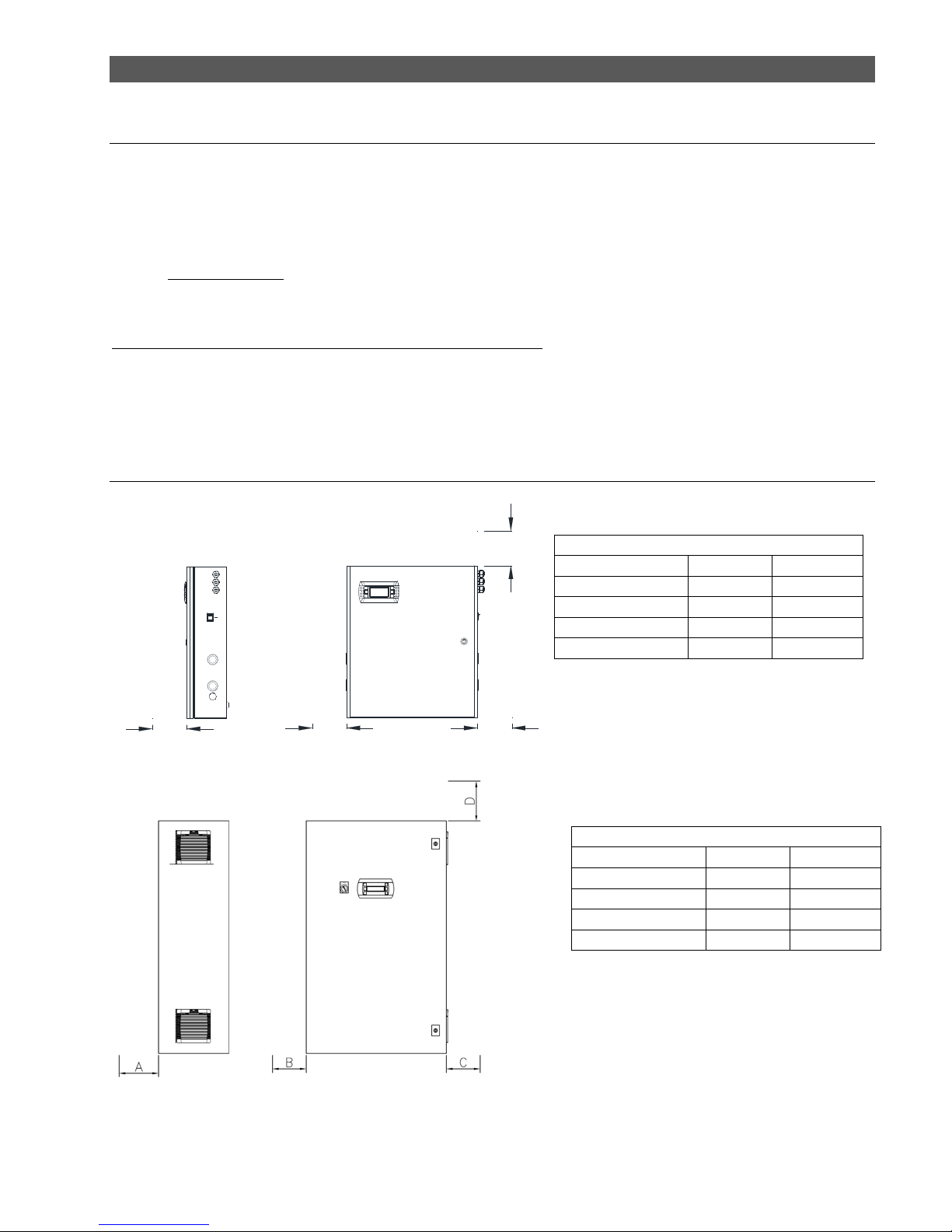
2.6 ZONE CONTROL PANEL DIMENSIONS AND WEIGHTS
19.7" [500.3mm]
22.9" [580.5mm]
5.9" [150.0mm]
8.8" [223.0mm]
2.4" [62.2mm]
1.6" [39.7mm]
PROBE CABLE INLETS
ON / OFF SWITCH
4.8" [122.5mm]
2.1" [52.3mm]
2" [51.0mm]
1.2" [30.0mm]
2.4" [59.7mm]
3.3" [82.6mm]
3.5" [89.6mm]
4.8" [122.5mm]
7.6" [193.4mm]
8.8" [223.0mm]
Weight Table, UAZN***108
weight installed
lbs / kg 53 / 24
weight packaged
lbs / kg 66 / 30
Weight Table, UAZN***109
weight installed
lbs / kg 142 / 64.1
weight packaged
lbs / kg 190 / 86.2
Page 7 of 38

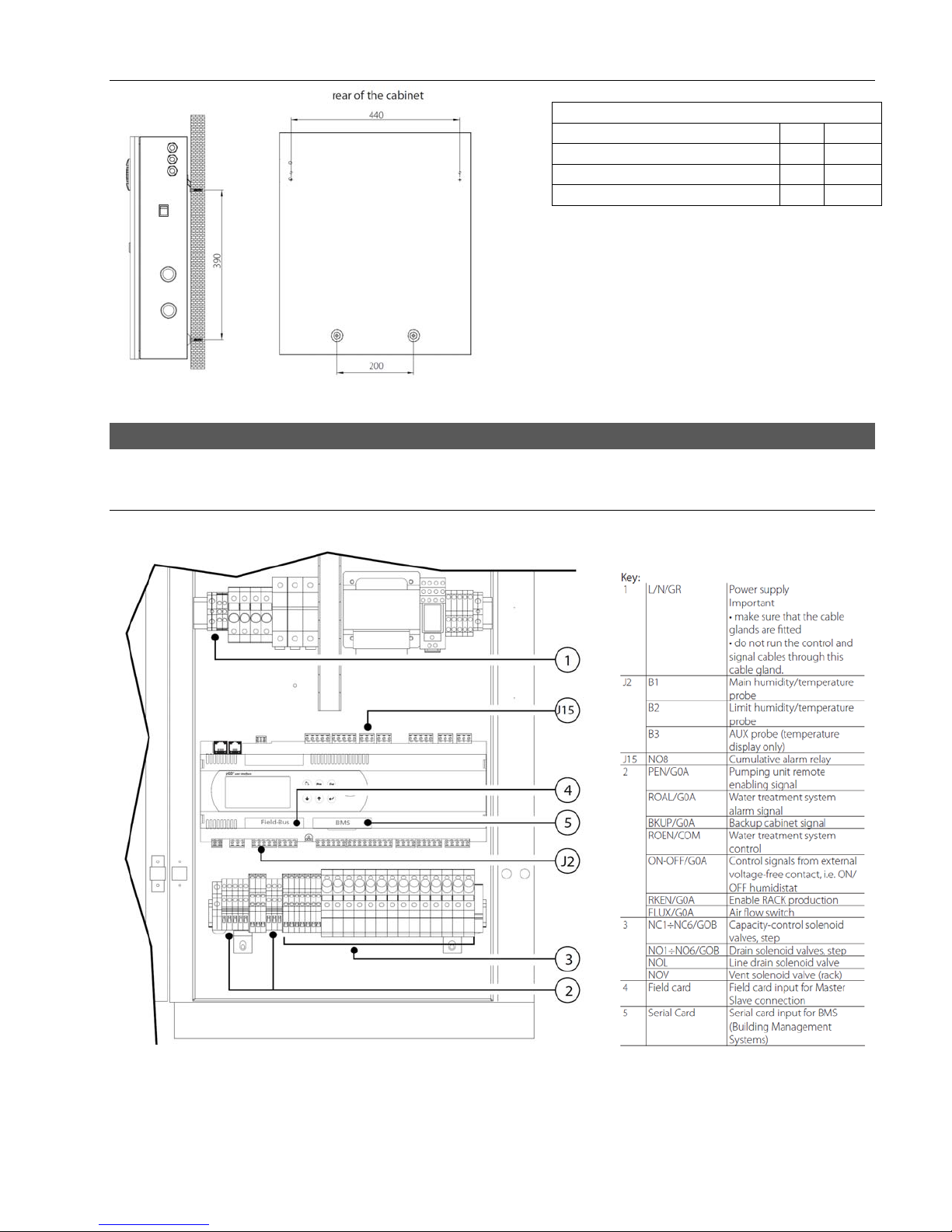
2.7 ZONE CONTROL CABINET COMPONENTS
1
2
8
9
7
6
3. MODELS
5
Key (UAZN***108)
1 terminal rear view
2 transformer B
3
3 main switch G
4 power supply terminal block
4
transformer primary fuse carrier
5
(TRA:F1,F2;TRB:F3,F4)
transformer B secondary fuse carrier
6
(F8)
7 transformer A
8 electroni c controller
9 control terminal block with fuses
Key(UAZN***109)
1 PGD
2 main switch G
3 Transformer A
4 Transformer B
5 Transformer C
6 Transformer A fuse carriers (F1,F2)
7 Transformer B fuse carriers (F4,F5)
8 Transformer C fuse carriers (F9,F10)
Fill and Drain fuse carriers (FU7, FU8,
9
FU11, FU12)
10 Controller Wiring fuse carri er (FU6)
Customer Power, Sensor and Alarm
11
Terminal Blocks (TBS1)
12 Power Supply Terminal Bl ocks (TBS2)
Fill/Drain Solenoid Terminal Blocks
13
(TBS3, TBS4)
Solenoid Valve Relays (RD1-9,RF1-
14
9,RV1)
15 electronic controller
3.1 ZONE CONTROL PANEL CODING GUIDE
UA
humiFog
Page 8 of 38
ZN 0 YYYY U
Zone Control
Cabinet Type of Cabinet Available – Sequencing Number Custom
0 = Standard U= USA
Zone Control Panels
4. ZONE CONTROL CABINET POSITIONING AND MOUNTING
4.1 ZONE CONTROL POSITIONING AND MOUNTING NOTES
The humiFog zone control cabinets are designed to be wall mounted. There are appropriate holes in the back of the
cabinet, for mounting to the wall. Use appropriate fasteners for supporting the weight of the cabinet and its components. Maintain
clearances around the cabinet as noted below. This allows for proper ventilation, maintenance and user operation of the cabinet.
The cabinet should be placed locally centered to the pumping station, and distribution zone points. For ducted systems, the zone
control cabinet should be close to the duct/AHU. For ambient systems, the zone control cabinet should be mounted centrally to
the zone areas.
IMPORTANT NOTE: The maximum distance between the zone control cabinet and the rack/distribution is 50ft
(15meters). It is recommended that the unit be fixed in position so that the electrical connections do not become damaged.
All connecting wiring is done by installer. Certain clearances must be maintained around the unit for safety and
maintenance.
The cabinet can be placed wherever the following conditions are met:
Cabinet protection index: IP20 / Nema Type 1 (unless specified otherwise)
Operating conditions: 20-80% RH non condensing, 34-104ºF (1-40ºC)
Storage conditions: 10-90% RH non condensing, 34-122ºF (1-50ºC)
4.2 ZONE CONTROL PANEL CLEARANCES
C
UNIT CLEARANCES (UAZN***108)
FACE OF UNIT DIM (IN) DIM (MM)
FRONT (D) 24 610
LEFT SIDE (B) 4 102
RIGHT SIDE (A) 4 102
TOP (C) 12 305
D
AB
Tab. 4.b
UNIT CLEARANCES (UAZN***109)
FACE OF UNIT DIM (IN) DIM (MM)
FRONT (A) 24 610
LEFT SIDE (B) 4 102
RIGHT SIDE (C) 4 102
TOP (D) 12 305
Tab. 4.b
Page 9 of 38
4.3 ZONE CONTROL DRILLING TEMPLATE
5. ELECTRICAL WIRING
5.1 WIRING CONNECTION LAYOUTS (UAZN***108)
Drilling Hole Conversion Table
Dimension mm in
Upper Horizontal 440 17.32
Lower Horizontal 200 7.87
Vertical Space Between Horiz. 390 15.35
Page 10 of 38

5.2 WIRING CONNECTION LAYOUTS (UAZN***109)
Page 11 of 38
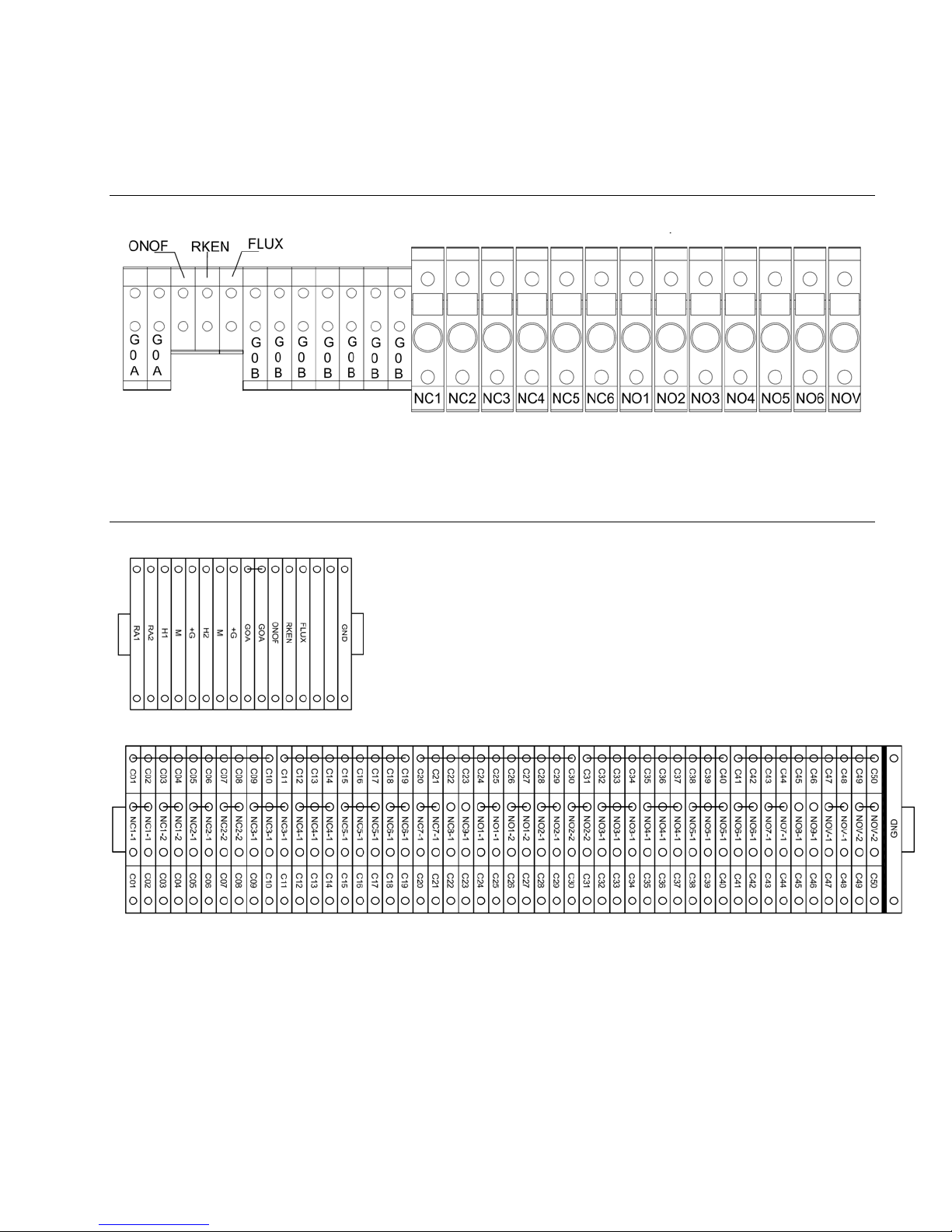
5.3 DETAILS OF (2) AND (3) TERMINAL BLOCKS (UAZN***108)
5.4 DETAILS OF (2)(TBS1) AND (3)(TBS3,TBS4) TERMINAL BLOCKS (UAZN***109)
(3)
(4)
Page 12 of 38
5.5 ELECTRICAL WIRING
Check that the power supply voltage to be connected matches the value indicated on the rating plate inside the electrical
panel.
An external, fused disconnect should be provided according to local and/or national electrical codes.
NOTE: To avoid unwanted interference, the power cables should be kept separate from
any control wiring.
All wiring must be in accordance with local, state and country electric codes.
NOTE: Tolerance allowed on main voltage = -15% to +10%
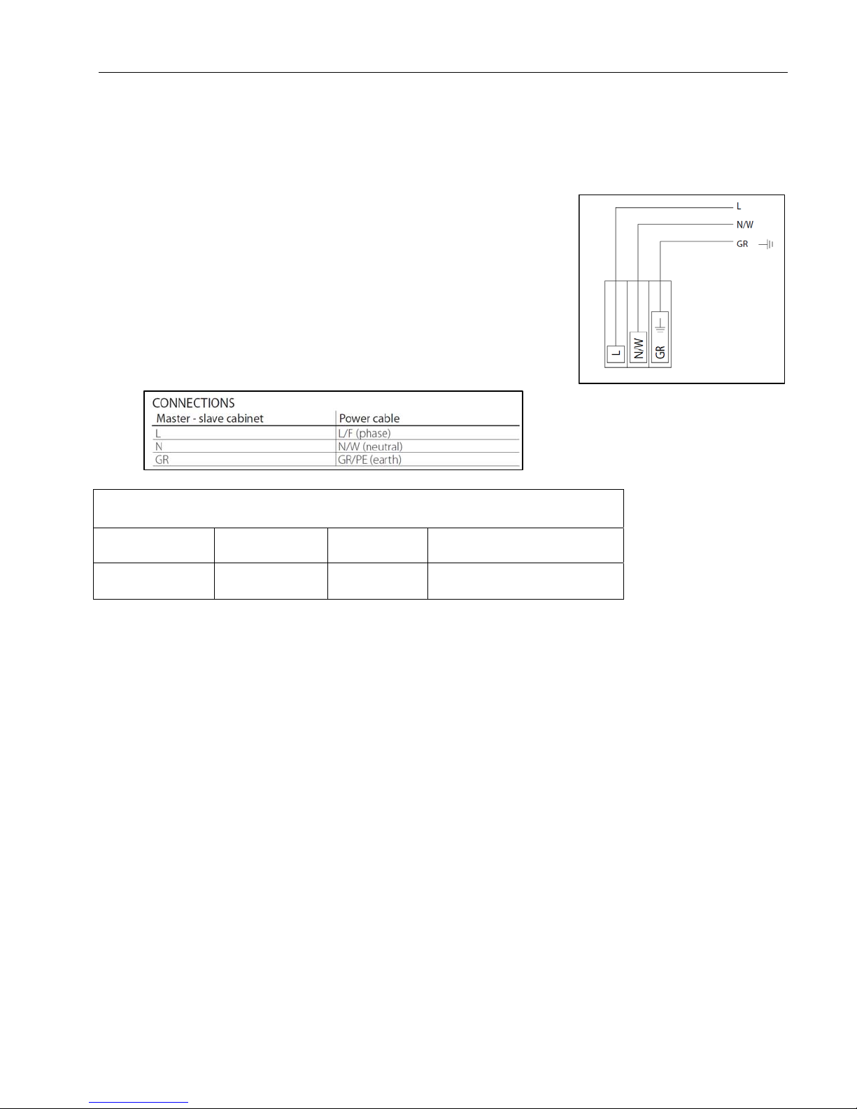
Power is connected to the main switch inside the control panel at the bottom right.
Connect wires to the top of the switch/terminal labeled L, and N. There is also a
ground bar/lug labeled GR
Power Table, UAZN******
External Disconnect Size,
Model Voltage Current
UAZN00108U 115 V~ 4.1 FLA at least 5 Amps
UAZN00109U 120 V~ 17.3 FLA at least 25 Amps
provided by Installer
Fig. 5.a
Page 13 of 38

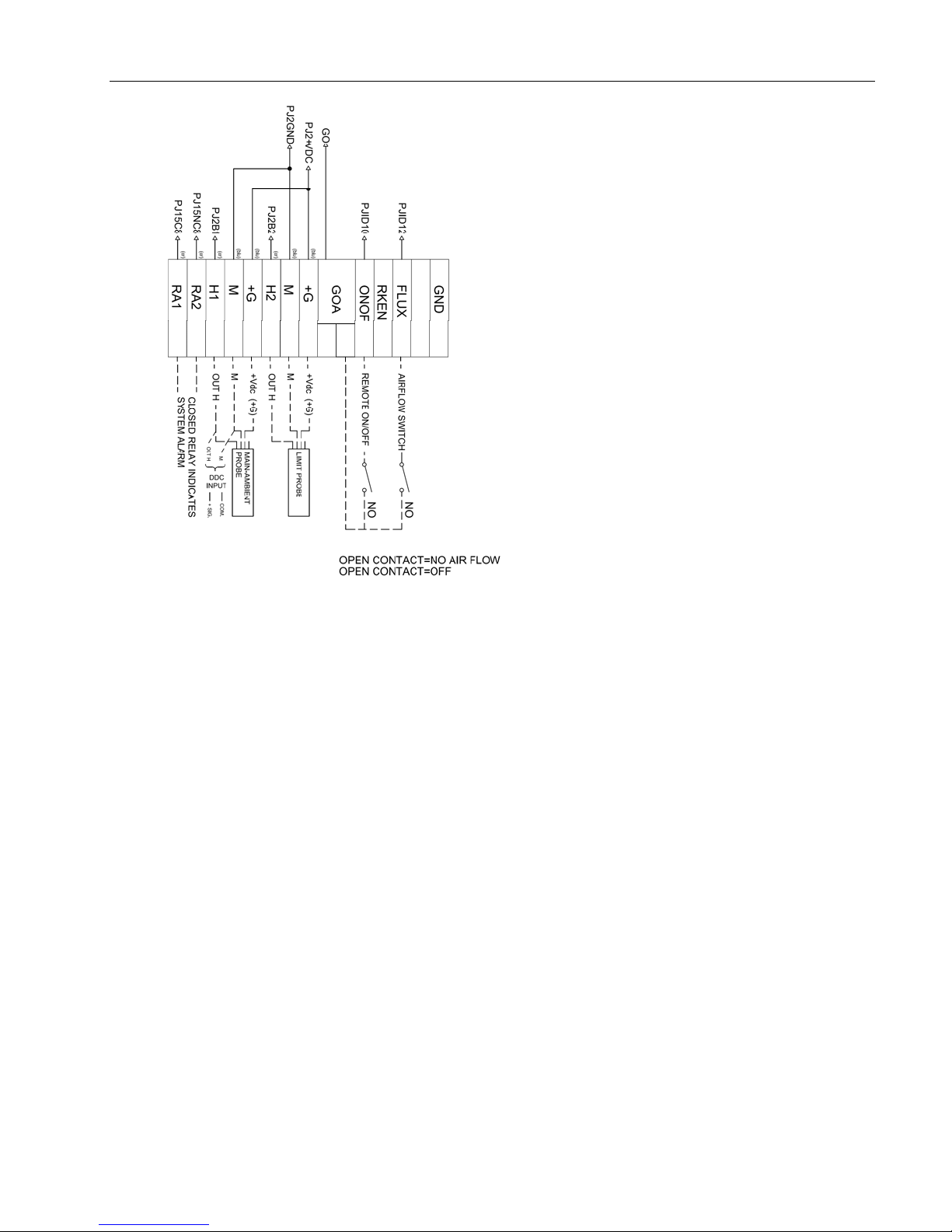
5.6 CONTROL SIGNALS FROM EXTERNAL VOLTAGE-FREE CONTACT
(HUMIDISTAT)(UAZN***108)
IMPORTANT NOTE: When grouping cabinets in a staged (cascaded) or parallel system, control signals, sensors, &
switches ONLY need to be connected to the master zone control cabinet of each group, addressed at location “1”.
Page 14 of 38

5.7 MODULATING CONTROL SIGNAL(UAZN***108)
IMPORTANT NOTE: When grouping cabinets in a staged (cascaded) or parallel system, control signals, sensors, &
switches ONLY need to be connected to the master zone control cabinet of each group, addressed at location “1”.
The control signal input connections depend on the control algorithm activated
Cables Up to 30 m : two-wire cables cross-section 0.5mm2
The signal may
come from:
To set the type of operation, control and signal: ”installer menu > type of control (see chap. 9.11 Installer menu)
-N.B. Shielded cables should be used. The cables must not run
near the 120 V power cables nor near the conductor cables;
this avoids measurement errors due to electromagnetic disturbance.
(AWG20)
-Modulating control with external controller
-Modulating control with ambient humidity probe
-External controller and limit humidity probe
Page 15 of 38
5.8 CONTROL SIGNAL WIRING (UAZN***109)
Page 16 of 38

5.9 SOLENOID VALVE CONNECTION FOR DISTRIBUTION SYSTEM (UAZN***108)
For the management of the distribution system, the cabinet controls four
types of solenoid valves:
• normally closed “NC” for capacity-control of the manifolds.
• normally open “NO” for draining the manifolds.
• normally open vent valves.
2
Recommended connection cables: two-wire plus earth AWG 18-20 (0.5-1.0 mm
maximum length 100 m.
REF.
1 NC1 - GOB 1 - 2
2 NC2 - GOB 1 - 2
3 NC3 - GOB 1 - 2
4 NC4 - GOB 1 - 2
5 NC5 - GOB 1 - 2
6 NC6 - GOB 1 - 2
7 N01 - GOB 1 - 2
8 N02 - GOB 1 - 2
9 N03 - GOB 1 - 2
10 N04 - GOB 1 - 2
11 N05 - GOB 1 - 2
12 NO6 - GOB 1 - 2
14 NOV - GOB 1 - 2
),
CABINET
TERMINAL
BLOCK
SOLENOI
D
VALVE
CONNEC
TOR
DESCRIPTION
Capacity-
control sol.
Valves 1st step
Capacity-
control sol.
Valves 2nd step
Capacity-
control sol.
Valves 3rd step
Capacity-
control sol.
Valves 4th step
Capacity-
control sol.
Valves 5th step
Capacity-
control sol.
Valves 6th step
Drain solenoid
Valves 1st step
Drain solenoid
Valves 2nd step
Drain solenoid
Valves 3rd step
Drain solenoid
Valves 4th step
Drain solenoid
Valves 5th step
Drain solenoid
Valves 6th step
Vent drain
solenoid valves
MAX. NO.
OF
SOLENOID
VALVES
PER STEP
3
3
3
1
1
1
3
3
3
1
1
1
1
Page 17 of 38

5.10 SOLENOID VALVE CONNECTION FOR DISTRIBUTION SYSTEM (UAZN**109)
The above diagram is meant to be a general guide.
See job specific submittal for UAZN***109 For wiring diagrams,
terminal block labeling and connections.
Label DESCRIPTION
CO1 - CO50 Commons For Valves
NC* Fill Valves
NO* Drain Valves
NOV* Vent Valves
Page 18 of 38

5.11 CUMULATIVE ALARM RELAY (J15)
5.12 INPUTS FROM EXTERNAL DEVICES
5.13 SUPERVISOR NETWORK
Supervisor network is through the pumping station unit. Please see the pumping station manual.
Page 19 of 38

5.14 PUMPING STATION TO MULTI ZONES
Pumping stations are wired to the multi-zone control panels by pLAN connections. Please see diagram below, as well as the
CAREL pCO platform manual for specific
instructions.
J11
RXTXRXTX+
Slave Pumping
Station
UA***H****
pLAN CONNECTION
J11
RXTX-
RXTX+
GND
GND
High pressure water line
Zone Control
Cabinet
UAZN*
Solenoid
Valve
Wiring
AHU
Zone Control
Solenoid
Valve
Wiring
J11
RXTX-
RXTX+
GND
Cabinet
UAZN*
AHU
Next zone,
if applicable
WIRING FROM PUMPING STATION, TO ZONE
CONTROL CABINET(S)
NOTES:
1. Use a twisted pair shielded cable to zone
control cabinets.
2. Connect to terminal block J11 of PCO3 in
each zone cabinet.
3. Connect the shield to the GND at pumping
station end only.
Page 20 of 38

5.15 DUPLEX CONTROL WIRING / MULTIPLE ZONES PER AIR HANDLER
WIRING FROM ZONE CONTROL CABINET TO
DUPLEX PUMPING STATIONS
NOTES:
1. Use a twisted pair shielded cable to pumping
stations.
2. Connect to terminal block J11 of PCO3 in each
pumping station.
3. Connect the shield to the GND at zone control
end.
Rx/Tx+ must match on all PCO controllers. Rx/Txmust also match on all PCO controllers.
For a duplex system, both pumping stations are wired to one or
more zone control panels by pLAN connections. Please see
diagram 6.d, as well as the CAREL pCO platform manual for specific
instructions.
For multiple zones in the same air handler, the same wiring rules apply for the pLAN connections. For multiple
zones each with multiple zone control cabinets, the number of cabinets per each zone must be the same. Contact the factory for
additional details regarding this.
Fig. 6.d
Page 21 of 38

6. START-UP
IMPORTANT INSTRUCTIONS/WARNINGS:
Before connecting the water to the pumping station, flush the supply pipe for 10 minutes by piping water directly into the
drain.
Before starting the pumping station, verify that the humidifier is in full operational condition. The hydraulic and electrical
equipment should not be locked out. There should not be any water leaks and the electrical components must be dry.
If a hazard does seem to exist, the system should be locked out immediately and the problems corrected before continuing.
6.1 STARTUP CHECKLIST
Before starting the humidifier, the following should be checked:
Water is connected, the line has been flushed, and external valves are open.
Drain is connected and run to an open drain.
Electricity is connected in accordance with instructions, local codes and data labels in the unit.
The external power fuses/disconnect are installed and intact.
All control wiring is done and tested.
Airflow switch is wired to open on air flow loss.
Hi-limit humidistat is wired to open on humidity rise above set point.
Unit wires have been checked to make sure they and all connectors are tight from shipping.
The high pressure water outlet piping is run correctly to the distribution system.
The proper capacities for each stage of the manifold system are installed in the zone control cabinet.
For a multi-zone system, the addresses of the zone controls cabinets are changed.
For a duplex system, the addresses of the pumping stations are changed.
6.2 RE-ADDRESSING THE CONTROLLERS AND DISPLAYS FOR MULTI-ZONE OR DUPLEX
SYSTEMS
The default addresses for a zone control cabinet are “1” for the PCO3 controller and “30” for the PGD display. The default
addresses for the pumping station cabinet are “16” for the PCO3 controller and “32” for the PGD display. For multi-zone or
duplex systems, the additional cabinets on the pLAN must have their addresses changed before they can operate correctly.
When changing addresses, the pLAN connections between each of the PCO3 controllers must be removed. The connections
are restored once the readdressing is completed.
For multi-zone system,
o the PCO3 controllers in the additional cabinets can be assigned addresses sequentially upward.
o the PGD displays in the additional cabinets can be assigned addresses sequentially downward.
For a duplex system,
o the PCO3 controller in the additional pumping station cabinet must be changed to “17.”
o the PGD display in the additional pumping station cabinet must be changed to “31.”
pLAN ADDRESS TABLE
Pumping
Station
Zone
Control
PCO3 Controller PGD Display
Default Multi-zone Duplex Default Multi-zone Duplex
16 N/C 17 32 N/C 31
1 2, 3, …, 15 N/A 30 29, 28, …, 18 N/A
Tab. 7.a
Page 22 of 38

6.3 RE-ADDRESSING PCO3 CONTROLLER
To change the address of the PCO3 controller, the address of the PGD display must be set to “0” first. (The procedure for
setting the address of the PGD back to the proper address is described in 6.2.2.)
1. Unplug J11 connector from PCO3 controller.
2. Press the up, down, and enter keys (3 keys on the right hand side of remote display) for approximately 3 seconds.
3. The screen should show “Display address setting.”
4. Press the enter key and change value to “0.”
5. Press enter.
6. Shut down power to the PCO3 controller, wait 3 sec, and then turn power back on to the PCO3 controller.
7. As unit is powering on, press and hold the up and alarm buttons (top left and top right buttons on PGD remote
display) until “pLAN address” is displayed.
8. Change to desired address.
9. Press enter.
10. The PCO3 is now address to the value you last entered.
6.4 RE-ADDRESSING PGD DISPLAY
1. Unplug J11 connector from PCO3 controller.
2. Press the up, down, and enter keys (3 keys on the right hand side of remote display) for approximately 3 seconds.
3. The screen should show “Display address setting.”
4. Press the enter key and change this value to 18-32. This address must be different from the address of the PCO3
controller.
5. Press enter.
6. Press the up, down, and enter keys (3 keys on the right hand side of remote display) for approximately 3 seconds.
7. You will be taken to the same screen as before, but this time you will see “I/O Board Address” displayed underneath
“Display address setting.”
8. Press the enter button 2 times so the text box is blinking beside “I/O Board address.”
9. Change this to the same address that you assigned to the PCO3 controller.
10. Then, press enter.
11. The next screen displayed will show “Terminal config” press enter to continue.
12. The following screen will show P:(address of PCO3 controller) in upper left corner.
13. Trm1 None will be blinking. Change “none” to the addressed you entered in step 4 (address of PGD display.)
14. Press enter 1 time and change the next field to Pr.
15. Press enter 5 times and change ok? From no to yes.
16. Press enter.
17. The PGD remote display is now addressed to your PCO3 controller.
Page 23 of 38

7. THE humiFog CONTROLLER
The humiFog controller features a comprehensive information display that shows the operation of the system at a glance:
Alarm
Program
Escape
Up
Enter
Down
+
Up +
Down
Turns off the buzzer and displays the first alarm screen in the alarm-loop.
A red LED located under the Alarm button will be energized when there are alarms present. If the red
LED is blinking, that means an alarm has occurred, but the condition has been corrected and the alarm
can now be reset.
Shortcut to the Technician’s Menu, where all application settings can be reached. If protected, a
password will need to be entered.
Escapes to previous screen-loop. When already in the Technician’s Menu, pressing ESC takes you to the
main status screen.
If ESC’s green LED is blinking, part of the system is under “Manual Control.”
Cycles upward through the screens, when cursor is in top left corner. When cursor is in a field, the value
of the field is increased. The longer the button is held, the faster the value increases.
Cycles through fields in a screen. When in a field, pressing ENTER confirms the current value into the
field and goes to the next field.
Cycles downward through the screens, when cursor is in top left corner. When cursor is in a field, the
value of the field is decreased.
The longer the button is held, the faster the value decreases.
Shortcut to quickly see the Software Application’s Version Number and Date.
It is in this screen from which you can restore the Factory Settings,
+
+
NOTE: The standard humiFog display will have fields that can display values or fields that can accept values. If pressing the
ENTER key places the cursor next to the display field, the UP and DOWN keys can be used to change that value.
Page 24 of 38
Escape +
Program
Escape +
Alarm
by pressing
Shortcut to quickly see the System Type and Number of Humidification Stages.
When in the Alarm History Screen, pressing ESC+PRG will erase the history.
Keyboard shortcut to reset all Manually controlled points to Automatic control.
When in the System Run Hours screens, pressing these keys will reset the currently selected Stage’s Run
Hours.
, then , then , and finally one last time.
7.1 MULTI-ZONE IN SINGLE AHU SETUP OVERVIEW
Depending on the system setup variables, there can be significant differences in the user interface options. Some
options may have more selections to choose from, and some menu selections may be absent altogether.
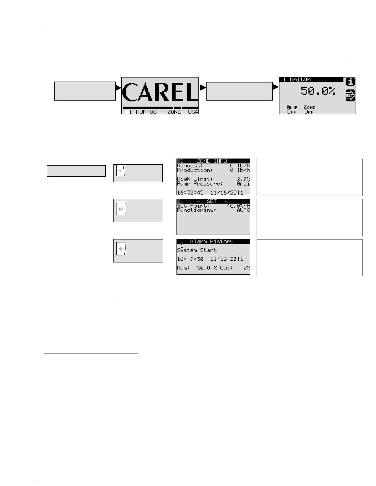
7.2 SYSTEM STATUS
On initial power-up, the controller will go through a series of self-tests and then activate the program, bringing up
the following screens. The visibility of some screens is dependent on the configuration of the system.
1. Power-up Unit
During power-up, the controller performs an alarm test. The alarm key will be red, and must be pushed twice to clear the
alarms. To check the “Alarm History”, use DOWN key from System Status Screen. The 1st alarm is a “System Start Alarm”, and
the 2nd alarm is a “No Air Flow Alarm”. Note: The “No Air Flow Alarm” occurs whether the AF digital input is open (low
voltage) or closed (high voltage) at power-up. Actions that can be performed from the System Status Screen:
System Status Screen
Up
Enter
Down
IMPORTANT NOTE: The System Status Screen can vary depending on the setup options in section 7.4 ,
MANUFACTURER SUBMENU. See section 5.11 for a review of multiple zone setup options. If the setup involves multiple zones
in the same air handler, choosing parallel or staged setup will change the System Status Screen as follows:
Parallel Zone Control: Each zone cabinet will display the same demand percentage because each cabinet is operating
simultaneously at the same level of output. The output level displayed is that of the entire zone & pumping system.
Staged (Cascaded) Zone Control: Zone control cabinets operate in a linear sequence, with zone activation occurring
only after the previous one has reached 100%. Due to the variation in demand among cabinets, the master cabinet (address
1) will display the demand value of entire system capacity. The remaining cabinet(s) will only display its own output relative
to its capacity. For example, the zone at address 1 may read 50%, indicating that the system capacity is 50% while the zone
demand at address 1 is actually 100%. For the subsequent zones, however, the demand displayed is the actual output of that
zone.
System Status Screen
No changes can be made at this
screen. It provides a summary of the
current zone and pump operation, as
well as system demand.
Use the ENTER key and UP/DOWN
key to change humidity SET POINT.
FUNCTIONING can be set to AUTO or
OFF. Use the ENTER key to activate
new value.
Use the UP/DOWN key to view alarms.
ESC key will take you back to previous
screen.
Page 25 of 38

7.3 MAIN MENU
A
Use
A
To access the “MAIN MENU”, press PRG from the “System Status Screen” shown above.
List of Main Menu selections: (Use the UP/DOWN arrows to scroll through this list)
1. User
2. Installer
3. Maintenance
.
r
1. Alarm threshold
2. Clock
B. Installer
1. Service Password
C. Maintenance
1. Service Password
To access the “Main Menu”, press PRG twice from the System Status Screen.
. On/Off Unit
1. On/Off Unit
B. Setpoint
1. Humidity Setpoint
C. Clock / Scheduler
1. Clock
Use the ENTER key and UP/DOWN
key to change the HIGH, LOW, and
ALARM DELAY values. When the
desired value is reached, use the
ENTER key to activate new value.
Use the ENTER key and UP/DOWN
key to change the MONTH, DAY,
YEAR, HOUR, and/or MINUTE. When
the desired values are reached, use
the ENTER key to activate the clock.
Manufacturer SubMenu (see below)
a. Configuration
b. I/O Configuration
c. Factory Settings
e. Initialization
Use the UP/DOWN keys to select
password and ENTER to confirm.
Access is granted to SERVICE MENU,
see 7.3 “SERVICE MENU” below.
Use the ENTER key and UP/DOWN
key to change to SWITCH OFF or
SWITCH ON. The “Actual state” will
change to “OFFbyKEY” or “UnitOn”.
Use the ENTER key to confirm.
Use the ENTER key and UP/DOWN
key to change the SET POINT. When
the desired value is reached, use the
ENTER key to activate new value.
Use the ENTER key and UP/DOWN
key to change the MONTH, DAY,
YEAR, HOUR, and/or MINUTE. When
the desired values are reached, use
the ENTER key to activate the clock.
Page 26 of 38

y
D. Input/Output
1. Analog Input
This screen displays the humidity
sensor reading or DDC value.
2. Digital Input
3. Relay Output
E. Data Logger
F. Board Switch
G. Service
1. Alarm Histor
1. Board Switch
b. Information
d. Working Hours
e. BMS config.
f. Service Settings
g. Manual Management
Displays the remote control state.
The “Off” state results from a “high”
voltage signal to the Remote On/Off
digital input port.
Displays the state of the relays. A
dark box, or “On” state, indicates a
“high” voltage signal to the solenoids
for that stage. (Screen layout varies
with number of stages.)
This screen displays the most recent
alarm. The UP and DOWN keys
allows scrolling through the entire
alarm history.
Displays information from the
controller at the indicated address. If
enabled, other controllers in a multizone installation can be selected. Up
to 32 zones can be connected.
Access is granted to SERVICE
MENU, see 7.3 “SERVICE MENU”
below.
Page 27 of 38
7.4 SERVICE MENU
To access the “Service menu”, scroll to “3. Maintenance” from “Main Menu”, and press ENTER when highlighted. The
factory default password is 22.
List of “Service Submenu” selections: (Use the UP/DOWN arrows to scroll through this list. Selections “a” and “c” are not
available.)
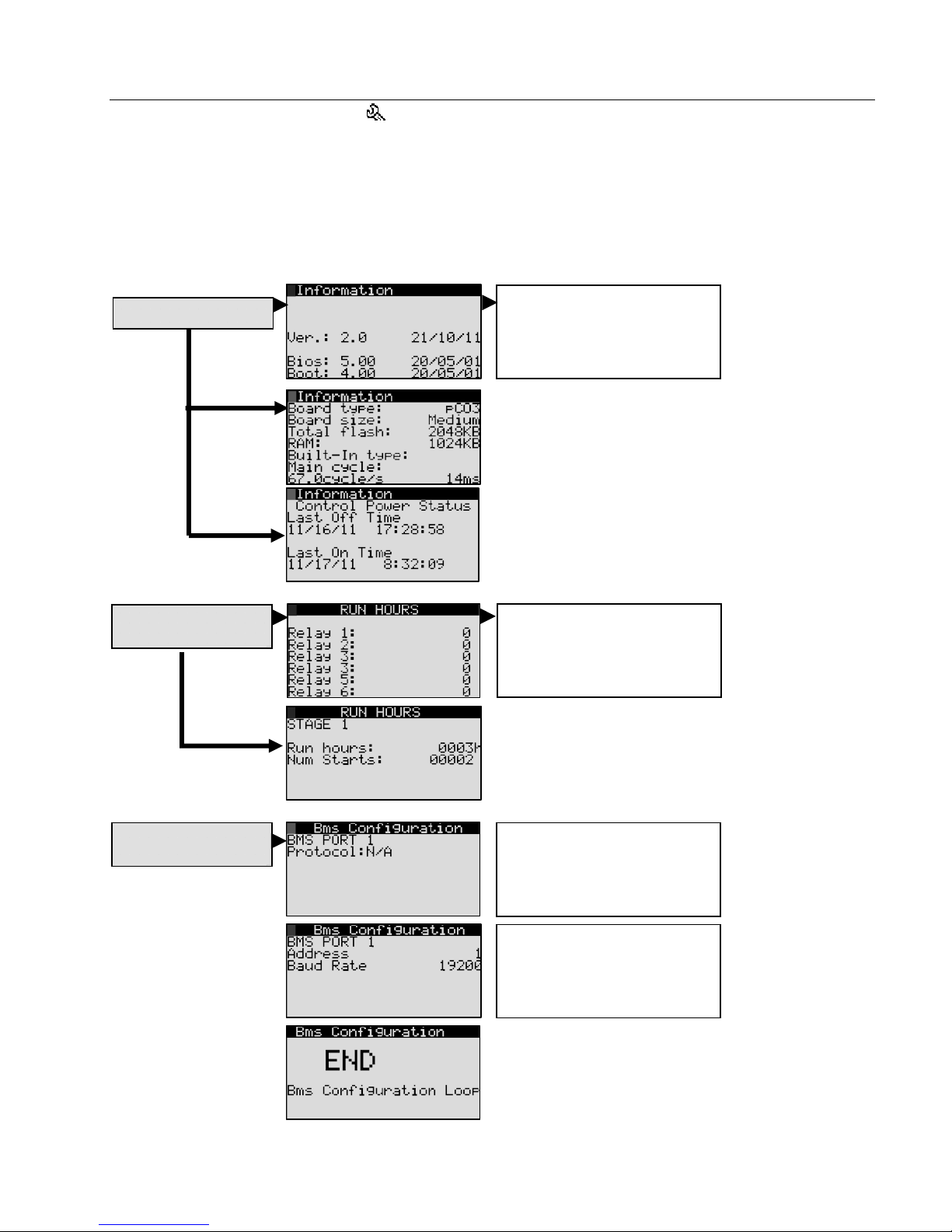
b. Information
d. Working Hours
e. BMS config.
f. Service Settings
g. Manual Management
b. Information
d. Working Hours
e. BMS config.
Page 28 of 38
Displays information on
controller software, hardware,
and power. Use the UP/DOWN
keys to alternate screens.
Displays cumulative run-time for
each stage. (Screen layout
varies with number of stages.)
Use ENTER to select Protocol
and UP/DOWN key to select
Protocol type. ENTER again to
confirm selection.
Use ENTER to select Address
or Baud rate and UP/DOWN
key to change. ENTER again to
confirm selection.

f. Service Settings
g. Manual Management
7.4.1 Service Settings Submenu
To access the “Service Settings Submenu,”
Scroll through the “G. Service” submenu to “F. Service Settings”
Press ENTER when “Service Settings Submenu” is highlighted.
Input the password.
List of Service Settings Submenu selections: (Use the UP/DOWN arrows to scroll through this list.)
a. Working hour set
b. Probe adjustment
c. Regulation
d. User DEV/Change PW1
a. Working hour set
b. Probe adjustment
c. Regulation
d. User DEV/Change
PW1
Use UP/DOWN key and
ENTER key to input password.
Default code is 22. The
password can be changed by
the service technician.
Use UP/DOWN key and
ENTER key to input password.
Default code is 22. The
password can be changed by
the service technician.
Use UP/DOWN key and
ENTER key to reset run hours.
Display will change momentarily
to Yes, and then will change
back to No.
Use UP/DOWN key and
ENTER key to choose Control
Sensor or High Limit Sensor.
Use the UP/DOWN key to
change the offset (0-53.5).
Default setting disables High
Limit Sensor, causing Value=0.
Use I/O configuration on
Manufacturer Submenu to
enable the High Limit Sensor.
Use the ENTER key and
UP/DOWN key to select and
change the Parameter values.
Consult Carel before making
changes.
Use the ENTER key and
UP/DOWN key to change the
Password. When the desired
value is reached, use the
ENTER key to activate.
Go to
Service Settings
Submenu
Go to
Manual Management
Page 29 of 38
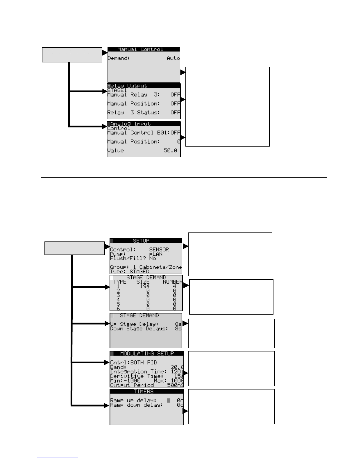
7.4.2 Manual Management Submenu
To access the “Manual Management Submenu,”
Scroll through main menu to “G. Service” and then “g. Manual Management”. Press ENTER and input the password.
g. Manual Management
Use the UP/DOWN keys to
scroll through screens.
DEMAND, STAGES, DRAINS,
RELAY OUTPUTS, DIGITAL
INPUTS, and ANALOG INPUTS
can all be controlled manually.
Use the ENTER key to select
the parameter being changed.
Use the UP/DOWN keys to
change the settings. (Screen
layout varies with number of
stages.)
7.5 MANUFACTURER SUBMENU
To access the “Manufacturer Submenu,” scroll through the “Main Menu” and select “B. Installer”. The settings in the
“Manufacturer Submenu” are password-protected. Unauthorized users should contact their Carel representative before
accessing the “Manufacturer Submenu.”
List of Manufacturer Submenu selections: (Use the UP/DOWN arrows to scroll through this list. Selection “d” is not available.)
a. Configuration
b. I/O Configuration
c. Factory Settings
e. Initialization
a. Configuration
Use the ENTER key and
UP/DOWN keys to change
control type, pump
communication, group/ type
quantity, and type (PARALLEL
or STAGED)
Use the ENTER key and
UP/DOWN keys to change the
water output for each stage to
match the humiFog system
being controlled.
Use the ENTER key and
UP/DOWN keys to change the
delay time for stage activation.
Page 30 of 38
Use the ENTER key and
UP/DOWN key to select and
change the Modulating Control
values. Consult Carel before
making changes.
Use the ENTER key and
UP/DOWN keys to change the
delay time for zone activation.

b. I/O Configuration
c. Factory Settings
e. Initialization
Use the UP/DOWN keys to
scroll through screens. Use the
ENTER and UP/DOWN keys to
Disable/enable inputs
Change RH signal type
o 0-1,5,10 VDC
o 4-20 mA
o NTC, -50T90, 10T 170,
nu10, PT1000, SPKP
o On/Off (Note: other
choices not used for RH)
Change max/min values
Use the UP/DOWN keys to
scroll through screens. Use the
ENTER key and UP/DOWN
keys to
Disable/enable inputs
Change the action (A
closed condition results in a
“high” voltage signal to the
digital input port.
Change time delay (up to
999 s)
Use the ENTER key and
UP/DOWN key to select and
change the Parameter values.
Consult Carel before making
changes.
Use the ENTER key and
UP/DOWN key to select and
change capacity setting.
Consult Carel before making
changes.
Use the ENTER key and
UP/DOWN key to reset all values
to global settings. To complete
initialization, turn unit off and on.
Use the ENTER key and
UP/DOWN key to select SAVE
options. There is an identical
screen for USER SAVE custom
options. ENTER will confirm the
choice.
Use the ENTER key and
UP/DOWN key to YES or NO.
Exercise caution when accessing
this screen since it can erase
everything.
Use the ENTER key and
UP/DOWN key to change access
passwords. ENTER will confirm
the selected digit.
Enabling the Remote
On/Off by a supervisor
requires a change to
the Factory Settings.
Page 31 of 38

8. REPLACEMENT PARTS
8.1 SEE SPECIFIC MATERIAL LIST(S) PROVIDED WITH UNIT.
1
8
Typical Zone Control Cabinet
2
Tab. 8.1
Item Description Part Number
8 CAREL PCO3 MEDIUM CONTROLLER
7 ISOLATION TRANSFORMER
3 MAIN SWITCH G
4 POWER SUPPLY TERMINAL BLOCK
2 MAIN CONTROL TRANSFORMER
TRANSFORMER B SECONDARY FUSE
6
CARRIER
5 TRANSFORMER PRIMARY FUSE CARRIER
1 CAREL PGD DISPLAY PGD1000FW0
9 CONTROL TERMINAL BLOCK PLUS FUSES
7
9
6
5
CONTACT
CAREL
CONTACT
CAREL
CONTACT
CAREL
CONTACT
CAREL
CONTACT
CAREL
CONTACT
CAREL
CONTACT
CAREL
CONTACT
CAREL
3
4
Page 32 of 38

S90
PGD
From Previous
Zone Cabinet
(J11) or Pump
Cabinet (J11)
RXTX-
RXTX+
GND
To Next Zone
Cabinet (J11)
TB-NC1 TB-NC2
B
NO2
NO1
C1
B B
NO3
C1
C4
9. WIRING DIAGRAM
TB-NC5
TB-NC3
B
NO7
NO6
NO5
NO4
C7
C7
C4
TB-NC4
NO8
NC8
NO10
NO9
C8
C9
OPEN RELAY INDICATES
SYSTEM ALARM
NO11
TB-NC6
C9
NO12
NC12
C12
TB-N01 TB-N02
NO13
NC13
C13
C14
TB-N03
TB-N04
BB
NO15
NO16
NO14
C14
C17
NO18
NO19
NO17
NO20
C17
J10
J9
J11
J12
J13
J14
J15
J16
J17
J18
J21
J22
3
Extra-Large
C21
B
TB-N05
TB-N06
NO21
J19
NO23
NO22
TB-N0V
J20
NO25
NO28
NO24
C25
C21
NO29
NO27
NO26
C25
J24
J1
+Vterm
GND
G0
G
J2
+5 Vref
GND
B3
B2
B1
J3
+VDC
BC4
BC5
B5
B4
GA
VG0
VG
TB-GOA
J4
Y3
Y4
Y2
Y1
J5
IDC1
ID8
ID7
ID4
ID3
ID5
ID2
ID1
ID6
B8
GND
ID9
TB-ONOF
M
+(G)
OUT H/T
M
+(G)
OUT H/T
REF
OUT.DDC
J7
ID12
ID10
ID11
TB-FLUX
0-10V AMBIENT
ID13H
IDC9
ID13
0-10V LIMIT
PROBE
PROBE
0-10V EXT.
CONTROL
J8
IDC13
ID14
ID14H
G0A
GA
0
B
G0B
GB
F5
F8
TR-A
0
24
TR-B
00
24
120
120
T1
T2
T3
F1
F2
F3
G
F3
F4
N
L
GR
N
L
120
VAC
GND
DISCONNECT SWITCH AND LISTED
PRIMARY OVER--CURRENT
PROTECTION TO BE PROVIDED BY
INSTALLER
T4
F4
Panel Builder Wiring
Final Assembly or Customer Wiring
Page 33 of 38

NOTES:
1. CABINET AND WIRING MUST BE UL508A ASSEMBLED.
2. CABINET SHALL BE CONTRUCTED WITH FINGERSAFE COMPONENTS.
3. CABINET SHALL BE CONTRUCTED AS TYPE 12.
4. WIRE COLORS SHALL BE AS FOLLOWS:
Black - All ungrounded conductors operating at supply voltage (wire numbers 1-4)
Red - Ungrounded AC control conductors at below supply voltage (all wires unless marked otherwise)
Orange (or) - All ungrounded conductors that remain energized when the main disconnect switch is "off"
Blue (blu) - Ungrounded DC control conductors at below supply voltage
White - All grounded AC current-carrying conductors, regardless of voltage
White w/ orange stripe - All grounded AC current-carrying conductors that remain energized when the
main disconnect switch is "off"
White w/ blue stripe - All grounded DC current-carrying conductors,regardless of voltage
Green( w/ or w/o yellow stripe) - Earth grounding.
NO1
NO2
NO3
NO4
NO5
NO6
NO9
NO7
NO10
NO11
NO12
NO14
NO15
NO16
NO17
NO18
NO19
NO20
NO21
NO23
NO22
TRA-0V
PCO PCO3000AS0
PGD PGD1000FW0
G MAIN DISCONNECT SWITCH
TR-A
TR-B
F1, 2
F3, 4
F5
F8
FNC*
NO*
NOV
NC*
NO*
NOV NO VENT VALVE
S90 PCO-PGD CABLE
ID10
ID12
TRANSFORMER (PCO)
TRANSFORMER (RELAYS)
FUSE: 5X20 1A 250V FAST
FUSE: 5X20 4A 250V SLOW
FUSE: 6.3X32 3.15A 250V SLOW
FUSE: 10.3X38 20A 600V FAST
FUSE: 5X20 6.3A 250V FAST
NC FILL VALVES (STAGE #)
NO DRAIN VALVES (STAGE #)
0
TERMINAL JUMPER
GOA
ONOF
G
0
B
AIR FLOW SWITCH
HUMISTAT-REMOTE ON/OFF SWITCH
0
0
B
B
COM FOR
0
B
ONOF
FLUX
0
B
0
0
B
B
G
G
G
G
G
G
NC1 NC2 NC3 NC4 NC5 NC6 NO1 NO2 NO3 NO4 NO5 NO6 NOV
1
2
3
4
5
6
7
8
9
10
11
12
14
NO
OPEN CONTACT=NO AIR FLOW
NO
OPEN CONTACT=OFF
FLUX
RKEN
GOA
Page 34 of 38

WIRING DIAGRAM FOR UAZN***109
Page 35 of 38

Page 36 of 38

10. WARRANTY
Limited Warranty
All products manufactured by CAREL USA, LLC are warranted to the original purchaser to be free from defects in materials and
workmanship in the course of normal and reasonable use for a period of 2 years and 1 month from the date of shipment (The
OEM controls warranty is 2 years from date of manufacture), humidifier replacement parts warranty is 90 days from date of
Invoice. Warranty replacement parts are warranted for remainder of original unit warranty or 90 days, whichever is longer, so
long as the product has been installed and operated in accordance with all appropriate manuals and wiring diagrams, and
started up by a qualified CAREL USA technician. Any product or part that is found to be defective will, at the option of CAREL
USA, LLC be replaced or repaired. CAREL USA, LLC reserves the right to inspect any part or installation before replacing or
repairing defective parts. After startup of the product, labor for repairs or replacement of parts is not covered by this warranty.
Products not included in this warranty are NTC and PTC probes, transformers (TRA series), and routinely replaceable parts
such as filters, nozzles, pump parts, and gaskets. CAREL USA, LLC assumes no liability for consequential or inconsequential
damage, or damage due to negligence or improper use. Under the terms of this warranty, the original purchaser may have
certain legal rights and other rights, which may vary from state to state. The Warranty will not be considered valid if a product
is damaged due to negligence, mishandling or misapplication, or if the product label is missing. CAREL USA will attempt to
repair or replace the products within two (2) months of the receipt of the returned goods.
NOTES
Page 37 of 38

Page 38 of 38
+03U222081 Rel. 2.0 13/12/2012
 Loading...