


CO
2
High e ciency condensing unit
OEM user manual
READ CAREFULLY IN THE TEXT!
Integrated Control Solutions & Energy Savings
NO POWER
& SIGNAL
CABLES
TOGETHER


ENG
WARNINGS
CAREL bases the development of its products on decades of experience in
HVAC, on continuous investments in technological innovations to products,
procedures and strict quality processes with in-circuit and functional testing
on 100% of its products, and on the most innovative production technology
available on the market. CAREL and its subsidiaries/affi liates nonetheless
cannot guarantee that all the aspects of the product and the software included
with the product respond to the requirements of the fi nal application, despite
the product being developed according to start-of-the-art techniques. The
customer (manufacturer, developer or installer of the fi nal equipment) accepts
all liability and risk relating to the confi guration of the product in order to
reach the expected results in relation to the specifi c fi nal installation and/or
equipment. CAREL may, based on specifi c agreements, acts as a consultant for
the positive commissioning of the fi nal unit/application, however in no case
does it accept liability for the correct operation of the fi nal equipment/system.
The CAREL product is a state-of-the-art product, whose operation is specifi ed
in the technical documentation supplied with the product or can be
downloaded, even prior to purchase, from the website www.carel.com.
Each CAREL product, in relation to its advanced level of technology, requires
setup/confi guration/programming/commissioning to be able to operate in
the best possible way for the specifi c application. Failure to complete such
operations, which are required/indicated in the user manual, may cause the
fi nal product to malfunction; CAREL accepts no liability in such cases. Only
qualifi ed personnel may install or carry out technical service on the product.
The customer must only use the product in the manner described in the
documentation relating to the product.
In addition to observing any further warnings described in this manual, the
following warnings must be heeded for all CAREL products:
• prevent the electronic circuits from getting wet. Rain, humidity and all
types of liquids or condensate contain corrosive minerals that may damage
the electronic circuits. In any case, the product should be used or stored
in environments that comply with the temperature and humidity limits
specifi ed in the manual;
• do not install the device in particularly hot environments. Too high
temperatures may reduce the life of electronic devices, damage them and
deform or melt the plastic parts. In any case, the product should be used
or stored in environments that comply with the temperature and humidity
limits specifi ed in the manual;
• do not attempt to open the device in any way other than described in the
manual.
• do not drop, hit or shake the device, as the internal circuits and mechanisms
may be irreparably damaged;
• do not use corrosive chemicals, solvents or aggressive detergents to clean
the device.
• do not use the product for applications other than those specifi ed in the
technical manual.
All of the above suggestions likewise apply to the controllers, serial cards,
programming keys or any other accessory in the CAREL product portfolio.
CAREL adopts a policy of continual development. Consequently, CAREL
reserves the right to make changes and improvements to any product
described in this document without prior warning.
The technical specifi cations shown in the manual may be changed without
prior warning.
The liability of CAREL in relation to its products is specifi ed in the CAREL
general contract conditions, available on the website www.carel.com and/
or by specifi c agreements with customers; specifi cally, to the extent where
allowed by applicable legislation, in no case will CAREL, its employees or
subsidiaries/affi liates be liable for any lost earnings or sales, losses of data
and information, costs of replacement goods or services, damage to things
or people, downtime or any direct, indirect, incidental, actual, punitive,
exemplary, special or consequential damage of any kind whatsoever, whether
contractual, extra-contractual or due to negligence, or any other liabilities
deriving from the installation, use or impossibility to use the product, even
if CAREL or its subsidiaries/affi liates are warned of the possibility of such
damage.
IMPORTANT
NO POWER
& SIGNAL
CABLES
READ CAREFULLY IN THE TEXT!
Separate as much as possible the probe and digital input cables from cables
to inductive loads and power cables, so as to avoid possible electromagnetic
disturbance.
Never run power cables (including the electrical panel cables) and signal
cables in the same conduits.
TOGETHER
DISPOSAL
INFORMATION FOR USERS ON THE CORRECT HANDLING OF WASTE
ELECTRICAL AND ELECTRONIC EQUIPMENT (WEEE)
In reference to European Union directive 2002/96/EC issued on 27 January
2003 and related national legislation, please note that:
• WEEE cannot be disposed of as municipal waste and such waste must be
collected and disposed of separately;
• the public or private waste collection systems defi ned by local legislation
must be used. In addition, the equipment can be returned to the distributor
at the end of its working life when buying new equipment;
• the equipment may contain hazardous substances: the improper use or
incorrect disposal of such may have negative eff ects on human health and
on the environment;
• the symbol (crossed-out wheeled bin) shown on the product or on the
packaging and on the technical leafl et indicates that the equipment has
been introduced onto the market after 13 August 2005 and that it must be
disposed of separately;
• in the event of illegal disposal of electrical and electronic waste, the
penalties are specifi ed by local waste disposal legislation.
Warranty on materials: 2 years (from production date, excluding consumables).
Approval: the quality and safety of CAREL S.P.A. products are guaranteed by
the ISO 9001 certifi ed design and production system.
3
Hecu CO2 +0300085EN rel. 2.2 - 07.05.2019

ENG
Hecu CO2 +0300085EN rel. 2.2 - 07.05.2019
4

Content
1. INTRODUCTION 7
1.1 General features .............................................................................................. 7
1.2 Components and accessories ......................................................................7
2. INSTALLATION 8
2.1 Main board: description of the terminals .................................................. 8
2.2 10A single-phase inverter .............................................................................. 9
2.3 12-16 A single-phase, 18-24 A three-phase inverter .............................. 10
2.4 12 A single-phase inverter PSD2 ............................................................... 11
2.5 Unipolar E2V valves for R744 ..................................................................... 14
2.6 Pressure probes (SPKT00**8C0) ..............................................................14
2.7 Temperature probes .....................................................................................14
2.8 General connection diagram ...................................................................... 15
2.9 Functional diagrams ..................................................................................... 16
2.10 Installation ...................................................................................................... 18
3. USER INTERFACE 19
3.1 Graphic terminal ...........................................................................................19
3.2 Description on the display .......................................................................... 19
ENG
4. MENU DESCRIPTION 20
4.1 Main menu ..................................................................................................... 20
5. COMMISSIONING 21
5.1 Guided commissioning procedure ........................................................... 21
6. FUNCTIONS 22
6.1 Unit ON/OFF .................................................................................................. 22
6.2 BLDC compressor .........................................................................................22
6.3 Compressor control ......................................................................................25
6.4 Compressor management on LT units (DSS and independent) .......27
6.5 Fans ..................................................................................................................28
6.6 Oil management ...........................................................................................29
6.7 HPV valve management .............................................................................. 32
6.8 RPRV valve management ............................................................................ 33
6.9 Generic functions ..........................................................................................34
6.10 Default value management ........................................................................ 35
7. FAST COMMISSIONING 36
7.1 MPXPRO confi guration (SW version t 4.0) ............................................ 36
7.2 Ultracell confi guration (SW version t 2.0)..............................................38
7.3 Ultra EVD EVO module commissioning ..................................................43
7.4 Connecting MPXPRO/Ultracella controllers to Hecu ............................44
8. SIGNALS AND ALARMS 47
8.1 Alarm management ......................................................................................47
8.2 Compressor alarms ...................................................................................... 47
8.3 Pressure alarms .............................................................................................48
8.4 Anti liquid return MPX valve alarm .......................................................... 49
8.5 High pressure prevention ...........................................................................49
8.6 MPXPRO/UltraCella alarms .........................................................................49
8.7 Alarm table .....................................................................................................50
9. SOFTWARE UPDATE 58
9.1 Uploading/updating the software .............................................................58
9.2 Software revision history ............................................................................. 61
5
Hecu CO2 +0300085EN rel. 2.2 - 07.05.2019


1. INTRODUCTION
ENG
1.1 General features
Hecu CO2 is a control system for complete management of R744
condensing units fi tted with BLDC compressors. The serial connection
between the condensing unit and the evaporators controlled by
MPXPRO/UltraCella and CAREL EEV expansion valves represents one of
the main features of this solution, contributing to the energy effi ciency
and reliability of the entire system. The control board is designed for
DIN rail assembly and is fi tted with plug-in screw terminals, as well
as incorporating a driver for managing two electronic expansion
valves. A user terminal (PGDe or pLDpro) is also available for service or
commissioning the system.
Main features:
• Modulation of cooling capacity by BLDC compressor with inverter;
• Management of a fi xed-speed backup compressor;
• Management of two modulating fans;
• Card with built-in driver for CAREL unipolar valves;
• Management of unipolar high-pressure valve (HPV);
• Management of unipolar fl ash gas valve (RPRV );
• Serial communication with evaporators (max 5);
• RS485 serial for BMS;
• Floating suction pressure set point;
• Floating condensing pressure set point;
• Advanced algorithm for calibrated oil injection to the compressor;
• Oil speed boost for oil return to the compressor;
• Oil recovery washing for oil return to the compressor;
• Vast confi guration of defrost functions;
• Suction and discharge superheat control;
• Ample confi guration of alarms.
1.2 Components and accessories
Part number Description
A ECU70TS0C0 Hecu CO2 controller, 230Vac, RTC, 2 unipolar EEV,
A ECU70TS0D0 Hecu CO2 controller, 230Vac, RTC, 2 unipolar EEV,
A ECU80TS0C0 Hecu CO2 controller, 24Vac, RTC, 2 unipolar eev,
A ECU80TS0D0 Hecu CO2 controller, 24Vac, RTC, 2 unipolar EEV,
A PSD101021A Power+ 10 A, 200-240 Vac 1Ph, IP00
A PSD1012200 Power+ 12 A, 200240 Vac 1Ph, IP20/IP44
A PSD1016200 Power+ 16 A, 200240 Vac 1Ph, IP20/IP44
A PSD1018400 Power+ 18 A, 280480 Vac 3Ph, IP20/IP44
PS20012204110 POWER+ 12 A, 200-240 Vac 1PH, IP20 PEC
A
PS20015204110 POWER+ 15 A, 200-240 Vac 1PH, IP20/IP44 PEC
A
PS20018404110 POWER+ 18 A, 380-480 Vac 3PH, IP20/IP44 PEC
A
PS20012204100 POWER+ 12 A, 200-240 Vac 1PH, IP20
A
PS20015204100 POWER+ 15 A, 200-240 Vac 1PH, IP20/IP44
A
PS20018404100 POWER+ 18 A, 380-480 Vac 3PH, IP20/IP44
A
PSACH10100 Coil for POWER+ 18 A
A
M E2V**CS1C0 Electronic expansion valve E2V**C 1313 S.
M E2VSTA03*0 Unipolar stator coil with cable *m
M E2VFIL0100 Filter kit for valve E2VBSF (conn. diam. 12 ODF) 10 pcs
M SPKT00H8C0 Press.Trasd. 4-20 mA 0...120 barg (0...1740 psig) sealed gage
M SPKT00D8C0 Press.Trasd. 4-20 mA 0...150 barg (0…2175 psig) sealed gage
A SPKT00L1S0 Press.Trasd. 0-5V 0…90 barg sealed gage packard 1/4 gas F
M SPKC002310 Cable AWG 3 wires l=2m for SPKT packard vulcanised - IP67
M NTC0**HT41 IP55, ** m cable, 0T150 °c, multiple package (10 pcs)
M NTC0**HF01 IP67, ** m cable, fast reading NTC probe strap-on plastic
O NTC0**WH01 Wh NTC sensor IP68 -50T105 cable **m
A PGDEH31FX0 pGDe terminal Hecu LOGO, pLAN version
A PLD00GFP00 PLDPro LCD neutral, 132x64 pixels, pLAN version
M S90CONN00* Connection cable between terminal and pCO
O PCOS004850 Opto-isolated RS485 serial connection card for pCO sistema
O PCOS00S030 Fastening bracket for RS485/Lon/RS232 serial card
Key:
M mandatory
(mandatory)
connector kit, no BMS, FLSMTDMCUTU
connector kit, no BMS, with plastic cover, FLSMTDMCUTU
connector kit, no BMS, FLSMTDMCUTU
connector kit, no BMS, with plastic cover, FLSMTDMCUTU
Steel high pressure without electrical coil
8-28V packard 1/4 gas male
8-28V packard 1/4 gas male
2
, l=*m
Tab. 1.a
A mandatory /
alternative
O optional
Hecu CO2 system example
Supervisor
RS485 max 5 unit
Fig. 1.a
7
Hecu CO2 +0300085EN rel. 2.2 - 07.05.2019

ENG
2. INSTALLATION
2.1 Main board: description of the terminals
For further details on the electrical and mechanical specifi cations, see
technical leafl et +050001590
Vout
RX-/TX-
J10
J15
J16
J17
J18
J19
J20
J21
J22
J23
J24
J11
J12
J14
J9
RX+/TX+
GND
RX-/TXRX+/TX+
GND
RX-/TXRX+/TX+
GND
N01
NC1
C1
Out2
C2
Out3
C2
Out4
C2
Out5
C2
C2
V-IN
Out6
C6
Out7
C7
Out8
C8
1
2
3
4
5b
- for UP2B*: 24 Vac +10%/-15% 50/60 Hz,
G0
28 to 36 Vdc +10%/-15%;
J1
U1
U2
J2
U3
GND
U4
U5
+Vdc
J3
+5VR
GND
U6
U7
+Vdc
J4
+5VR
GND
U8
U9
U10
J5
+Vdc
+5VR
GND
GND
Y1
J6
Y2
Y3
DI1
DI2
J7
DI3
DI4
GND
15
J13
J8
- for UP2A*: 230 Vac 50/60 Hz, +10%/-15%;
G
Fig. 2.a
Key:
1 Power 230 Vac for version with transformer (UP2A*********)
Power 24 Vac for version without transformer (UP2B*********)
2 Universal channels 9 Alarm digital output
3 Analogue outputs 10 pLAN serial connection
4 Digital inputs 11 BMS2 serial connection
5a Valve 1 output 12 Fieldbus serial connection
5b Valve 2 output 13 Connection for PLD terminal
6 Switching digital relay outputs 14 Dipswitch for settings
7 Voltage input for outputs 2, 3, 4, 5 15 BMS1 RS485 serial card
8 Digital outputs with voltage signal 16 Green power LED
Digital
inputs
Analogue
outputs
Type: digital inputs with voltage-free contacts
Number of digital inputs (DI): 4
Type: 0 to 10 Vdc cont., PWM 0 to 10 V 50 Hz synch. with power supply,
PWM 0 to 10 V frequency 100 Hz, PWM 0 to 10 V frequency 2 kHz
Number of analogue outputs (Y): 3
Universal
channels
Analogue/digital conversion bits: 14
Type of input selectable from application: NTC, PT1000, PT500, PT100, 4 to
20 mA, 0 to 1 V, 0 to 5 V, 0 to 10 V, voltage-free contact **
Type of output selectable from application: PWM 0/3.3 V 100 Hz
synchronous with power supply PWM 0/3.3 V 100 Hz, PWM 0/3.3 V 2 kHz,
0 to 10 V analogue output Maximum current 2 mA
Number of universal channels (U): 10
Precision of passive probe reading: ± 0.5 C across entire temperature
range; Precision of active probe reading: ± 0.3% across entire voltage
range; Output precision: ± 2%
Digital
outputs
Group 1, Switchable power R1: NO 1(1)A
Group 2, Switchable power R3, R4, R5: NO NO 2(2)A
Group 3, Switchable power R6, R7, R8: NO 6(6)A
Maximum switchable voltage: 250Vac
Switchable power R2 (SSR case mounting): 15 VA 110/230 Vac
The relays in the same group have basic insulation between each other
and therefore must have the same power supply
Relays belonging to diff erent groups have reinforced insulation and
consequently a diff erent power supply can be used
Unipolar
valve
outputs
Maximum power for each valve: 7 W
Type of control: unipolar
Valve connector: 6-pin, fi xed sequence
Power supply: 12 Vdc ±5%
Maximum current: 0.3 A for each winding
Minimum winding resistance: 40 Ω
Maximum cable length: 2 m
** max. 6 x 0 to 5 V rat. and 4 x 4 to 20 mA probes
14
12
11
13
5a
16
10
9
8
7
6
Tab. 2.a
Electrical and mechanical speci cations of the controller
Power supply:
230 Vac, +10…-15% UP2A*********;
24 Vac +10%/-15% 50/60 Hz,
28 to 36 Vdc +10…-15% UP2B*********;
Maximum power input: 25 VA
Insulation between power supply and controller
• 230 Vac model: reinforced
• 24 Vac model: reinforced guaranteed by power transformer
Maximum voltage of connectors J1 and J16 to J24: 250 Vac;
Minimum size of digital output wires: 1.5 mm
Minimum size of all other connector wires: 0.5 mm
2
2
Power supplied
Type: +Vdc, +5VR, Vout for external power supplies
+Vdc: 26 Vdc ±15% for 230 Vac model power supply (UP2A*********),
21 Vdc ±5% for 24 Vac model power supply (UP2B*********)
Max current available +Vdc: 150 mA total, taken from
all connectors, protected against short circuits
+5 VR: 5 Vdc ± 2%; maximum available current 60 mA, total
taken from all connectors, protected against short circuits
Vout: 26 Vdc ±15% for 230 Vac model power supply (UP2A*********),
21 Vdc ± 5% Maximum current available (J9): 100 mA
Product speci cations
Program memory (FLASH): 7 MB
Log memory: 4 MB
Internal clock precision: 100 ppm
Removable battery: Lithium button, CR2430, 3 Vdc
Battery lifetime: minimum 8 years
Terminal connections available
Type: all pGDe terminals with dedicated connector J15, PLD with
dedicated connector J10
Max distance for pGDe terminal: 2 m via telephone connector J15, 50
m via AWG24 shielded cable
Maximum number of connectable terminals: one pGDe series terminal
on J15 or J14; one PLD terminal on connector J10, selecting the tLAN
protocol on card dipswitches
Communication lines available
Type: RS485, Master for FieldBus1, Slave for BMS 2, pLAN
No. and type of lines available:
1 line, not opto-isolated on connector J11 (BMS2).
1 line, not opto-isolated on connector J9 (FieldBus), if not used by the
PLD terminal on connector J10.
1 line, not opto-isolated on connector J14 (pLAN), if not used by the
pGDe terminal on connector J15.
1 optional line (J13), selectable from the Carel options available
Max. connection cable length: 2 m via unshielded cable, 500 m via
AWG24 shielded cable
Maximum connection length
Universal digital inputs and anything else not specifi ed: less than 10 m
Digital outputs: less than 30 m
Serial lines: see specifi cations in the corresponding sections
Operating conditions
Storage: -40T70 °C, 90% rH non-cond.
Operation: -40T70 °C, 90% rH non-cond.
Physical speci cations
Dimensions: 13 DIN rail modules, 228 x 113 x 55 mm
Ball pressure test: 125 °C
Other speci cations
Environmental pollution: level 2
Ingress protection: IP00
Class according to protection against electric shock: to be incorporated
into Class I and/or II equipment
PTI250 for PCB insulation; PTI175 for other materials
Period of stress across the insulating parts: long
Type of action: 1C; 1Y for SSR versions
Type of disconnection or microswitching: microswitching
Heat and fi re resistance category: category D (UL94 - V2)
Immunity against overvoltages: category II
Software class and structure: Class A
Do not touch or tamper with the device when powered
Hecu CO2 +0300085EN rel. 2.2 - 07.05.2019
8

ENG
2.2 10A single-phase inverter
For further details on the electrical and mechanical specifi cations, see
technical leafl et +0500076IE
-DC
+DC
J2
J1
C
1
Fig. 2.b
Description of the terminals:
Ref. Description
L, N
earth conn. (*)
U, V, W
earth conn. (*)
-DC
+DC
J1-1 C
J1-2 NO
J2-3 0 V
J2-5 Tx/RxJ3-6 PTC
J3-7 24 Vdc
E
F (LED)
(*) The earth connections inside the controller are electrically connected together
and to the PE.
Single-phase power input
Motor output
DC bus output
Relay output (green connector)
RS485/ModBus® connectionJ2-4 Tx/Rx+
PTC input (black connector)
PE
POWER (green) drive powered
RUN/FAULT (green/red) drive running / active alarm
DATA (yellow) communication active
NO
2 3 4 5 6 7
J3
PTC
24Vdc
Tab. 2.b
CE conformity:
2006/95/EC
EN 61800-5-1: Adjustable speed electrical power drive systems. Safety requirements. Electrical, thermal and energy.
2004/108/EC
EN 61800-3, ed. 2.0: Adjustable speed electrical power drive systems. EMC requirements, including specifi c test methods.
EN61000-3-2: Electromagnetic compatibility (EMC) Part 3-2: Limits for harmonic
current emissions (equipment input current <= 16A per phase).
EN61000-3-12: Electromagnetic comp. (EMC) Part 3-12: Limits - Limits for harmonic current emissions (equipment input current > 16 A and <=75 A per phase).
Rated values
The following table shows the rated input current and output current
values, as well as the specifi cations for sizing the cables (cross-section,
maximum length) and the fuses. The values refer to an operating
temperature of 60°C and a switching frequency of 8 kHz, unless otherwise
specifi ed.
PSD10102BA
Rated input current at 230 V
Fuse or type B circuit breaker
Power cable size
Rated output current
Rated output power at 230 V
Maximum total dissipation
Maximum dissipation on the heat sink
Min. motor cable size
Max. motor cable length
17 A
25 A
4 mm
10 A
3.8 kW
270 W
150 W
2.5 mm
5 m
2
2
Tab. 2.d
Dimensions
6 87,1
4,8
78
Important: before carrying out any maintenance, disconnect the
drive and the control circuits from the power supply by moving the main
system switch to “off ”. Once having powered down the drive, wait at least
5 minutes before disconnecting the electrical cables;
Main technical speci cations
Operating temperature -20T60°C
Humidity < 95% RH non-condensing
Environmental pollution level Max 2
Input voltage 200 - 240V ± 10%, 50 - 60Hz, 1~
Output voltage 0 - Input voltage
Output frequency 0 - 500 Hz
Maximum length 5 m
Switching frequency 4, 6, 8 kHz
Protection functions
Frequency resolution 0.1 Hz
Inputs
Outputs
Serial input
24 Vdc auxiliary power supply Double insulation, 10% precision, 50 mA max
Maximum length 100 m shielded cable
Ingress protection IP00
Drive: short circuit, overcurrent, earth fault, overvoltage and undervoltage, overtemperature
Motor: overtemperature and overload (150%
Inom for 1 minute)
System: loss of communication
1 motor protection input: PTC temp. or voltage-free contact, maximum current 10 mA,
maximum length 25 m.
1 relay: programmable output, voltage-free
contact: 240 Vac, 1 A
RS485, Modbus® protocol, max baud rate 19200
bit/s
Tab. 2.c
177,6 40,9
197
Fig. 2.c
4,8
65,7 7,3 7,5
102,8 39,3
138
88
Ø5
M5
113,412,6 4
7055,8
6,9
209,5
9
Hecu CO2 +0300085EN rel. 2.2 - 07.05.2019

ENG
2.3 12-16 A single-phase, 18-24 A threephase inverter
For further details on the electrical and mechanical specifi cations, see
technical leafl et +0500048IE
C1
C2
F
E
L1/LL2/N L3UVW
Fig. 2.d
Description of the terminals:
Ref. Description
L1/L, L2/N, L3
earth conn. (*)
L1/L, L2/N
earth conn. (*)
U, V, W
earth conn. (*)
C1, C2
1.2 Relay output
30 V
5 Tx/Rx6 PTC input
7 24 Vdc
80V
9 STOa Safety digital input - Safe Torque
10 STOb
E
F (LED)
(*) The earth connections inside the controller are electrically connected together
and to the PE.
(**) To enable the drive to operate, apply a voltage of 24 Vac/Vdc to the Safe Torque
Off digital input. The polarity is indiff erent for direct current power supply.
Three-phase power input
Single-phase power input
Motor output
Terminals not used in PSD10**2 **, for optional DC choke on
PSD10184** and PSD10244**
PE
POWER (green) drive powered
RUN/FAULT (green/red) drive running / active alarm
DATA (yellow) communication active
1 2 345 678910
RS485/ModBus® connection4 Tx/Rx+
Auxiliary voltage
Off (**)
CE conformity:
2006/95/EC
EN 61800-5-1: Adjustable speed electrical power drive systems. Safety requirements. Electrical, thermal and energy.
2004/108/EC
EN 61800-3, ed. 2.0: Adjustable speed electrical power drive systems. EMC requirements, including specifi c test methods.
EN61000-3-2: Electromagnetic compatibility (EMC) Part 3-2: Limits for harmonic
current emissions (equipment input current <= 16A per phase).
EN61000-3-12: Electromagnetic comp. (EMC) Part 3-12: Limits - Limits for harmonic
current emissions (equipment input current > 16A and <=75A per phase).
Rated values
The following table shows the rated input current and output current
values, as well as the specifi cations for sizing the cables (cross-section,
maximum length) and the fuses. The values refer to an operating
temperature of 60°C and a switching frequency of 8 kHz, unless otherwise
specifi ed.
model
Rated input current at 230 V
Fuse or type B circuit breaker
Power cable size
Rated output current
Rated output power at 230 V
Maximum total dissipation
Maximum dissipation on the heat sink
Min. motor cable size
Max. motor cable length
PSD10122A0 PSD10162A0
22 A 28 A
32 A 40 A
4 mm
2
6 mm
2
12 A 16A
4.5 kW 6 kW
330 W 450 W
190 W 250 W
2.5 mm
2
2.5 mm
2
5 m 5 m
Tab. 2.f
model
Rated input current at 400 V 3PH
Fuse or type B circuit breaker
Power cable size
Rated output current
Rated output power at 400 V 3PH
Maximum total dissipation
Maximum dissipation on the heat sink
Min. motor cable size
Max. motor cable length
18A 3PH 24A 3PH
23 A 30 A
32 A 40 A
4 mm
2
6 mm
2
18A 24A
10.5 kW 14 kW
320 W 485 W
250 W 380 W
4 mm
2
4 mm
2
5 m 5 m
Tab. 2.g
Dimensions
173
127
Main technical speci cations
Reference technical document
Operating temperature -20T60°C
Humidity < 95% RH non-condensing
Environmental pollution level Max 2
Input voltage 200 - 240V ± 10%, 50 - 60Hz, 1~
Output voltage 0 - Input voltage
Output frequency 0 - 500 Hz
Maximum length 5 m
Switching frequency 4, 6, 8 kHz
Protection functions
Frequency resolution 0.1 Hz
Inputs
Outputs
Serial input
24 Vdc aux. power supply Double insulation, 10% precision, 50 mA max
Maximum length 100 m shielded cable
Ingress protection IP20
+0500048IE
Drive: short circuit, overcurrent, earth fault, overvoltage and undervoltage, overtemperature
Motore: overtemperature and overload (150%
Inom for 1 minute)
System: Safe Torque OFF input, loss of communication
1 motor protection input: PTC temp. or voltage-free contact, maximum current 10 mA,
maximum length 25 m.
1 relay: programmable output, voltage-free contact: 240 Vac, 1 A
RS485, Modbus® protocol, max baud rate 19200
bit/s
Tab. 2.e
268
240
24,6
24,6
86
12
27,9
2660
70,8
33,2
71,3
Fig. 2.e
26 2675
192,3
131
M5
80
82
190
289,2
Hecu CO2 +0300085EN rel. 2.2 - 07.05.2019
10
ENG
~
2.4 12 A single-phase inverter PSD2
For further details on the electrical and mechanical specifi cations, see
technical leafl et +0500120IE
cut this area and access to DIP switches
to set the ID (network) address
E
Fig. 2.f
Description of the terminals:
Ref. Description
L, N Single-phase power input
(*)
PE
U, V, W Motor output
(*)
PE
-DC DC bus output
+DC
GND (0V)
Tx/Rx+
Tx/RxSTO1 STO safety input
STO2
E
F (LED)
(*)
The earth connections inside the drive are wired together and to the PE.
Spade connectors
Spade connectors
Spade connectors
RS485/ModBus® connection
3-pin plug-in terminals
2-pin plug-in terminals
Earth screw
PE
POWER (green) drive powered
RUN (green) drive running
FAULT (red) drive alarm
DATA (yellow) communication active
3 4 5 6 7
STO
A B
Tab. 2.h
Important:
• before carrying out any maintenance, disconnect the drive and the
control circuits from the power supply by moving the main system
switch to “off ”. Once having powered down the drive, wait at least 5
minutes before disconnecting the electrical cables;
• always make sure that the motor has come to a complete stop. Freely
rotating motors may generate dangerous voltages across the Power+
terminals, even when this is not powered;
Rated values
The following table shows the rated input current and output current
values, as well as the specifi cations for sizing the cables (cross-section,
maximum length) and the fuses. The values refer to an operating
temperature of 60°C and a switching frequency of 8 kHz, unless otherwise
specifi ed.
PSD10102BA
Rated input current at 230 V 19.2 to
Fuse or type B circuit breaker
Power cable size
Rated output current
Rated output power at 230 V
Maximum total dissipation
Maximum dissipation on the heat sink
Min. motor cable size
Max. motor cable length
16 A
25 A
4 mm
12 A
3.8 kW
270 W
150 W
2.5 mm
5 m
Tab. 2.i
2
2
Dimensions
103 39.3
Main technical speci cations
Environmental conditions
Power supply
Motor output
Functions
Control unit
Inputs
Outputs DCbus power supply
Storage temperature -40T60°C
Operating temperature -20T60°C
Humidity < 95% RH non-condensing
Altitude
Environmental pollution level 3
Input voltage 200 - 240V / 105 -125V ± 10%, 50/60Hz, 1~
Output voltage 0 - Input voltage
Output frequency 0 - 500 Hz
Frequency resolution 0.1 Hz
Maximum cable length see paragraph 5.1
Switching frequency 4, 6, 8 kHz
Protection functions
Each drive must be connected in the network via Modbus® to a CAREL pCO or other manufacturer’s controller that manages the drives with Master/
Slave logic.
STO (Safe Torque Off )
for auxiliary devices
40.9177.7
87.1
197
220
78
113.4
148
Fig. 2.g
Maximum allowed: 2000 m above sea level
Up to 1000 m asl without derating
Derating in terms of maximum output current: 1% /100m
Drive: short circuit, overcurrent, earth fault, overvoltage and undervoltage, overtemperature
Motor: overload (150% Inom for 1 minute), stall
System: loss of communication,
Safety: STO (Safe Torque Off ), locked rotor
Voltage-free contact input, reinforced insulation (12 V SELV circuit):
open contact voltage: <24 V
closed contact current: 40 mA typical
max. cable length 25 m
395 Vdc ± 10 Vdc, 1.9 A max for PS2**122***** models;
max. cable length 1 m - shielded cable, minimum cross-section 1 mm
2
11
Hecu CO2 +0300085EN rel. 2.2 - 07.05.2019

ENG
Interface
data connection
Serial data connection
Insulation Reinforced (24 V SELV circuit)
RS485, Modbus® protocol, maximum baud rate 19200 bit/s - typical resistance in reception 96 KΩ (equal to
1/8 load unit, i.e. 1/256 of the maximum load applicable on the line)
Maximum length 100 m shielded cable
Ingress protection IP00
Ball pressure test temperature 125°C
Construction Device to be incorporated
Type of automatic action PS200122***0* and PS200122***S* Functional
PS200122***1* and PS200122***P* Safety
Pulse voltage 4 kV (overvoltage category III)
Conformity
to standards
Low voltage directive
CE
Compatibility directive
electromagnetic
2014/35/EU
IEC 60730-1, IEC 60335-1 (sections 29 and 30), IEC 60335-2-34 (sections 19.101 and 19.103)
2014/30/EU
EN 61800-3, ed.2.0: Adjustable speed electrical power drive systems. EMC requirements, including specifi c
test methods.
EN61000-3-2: Electromagnetic compatibility (EMC) Part 3-2: Limits - Limits for harmonic current emissions
(equipment input current <= 16 A per phase).
EN61000-3-12: Electromagnetic compatibility (EMC) Part 3-12: Limits - Limits for harmonic current emissions
(equipment input current > 16 A and <=75 A per phase).
UL UL 60730-1, UL 60335-1 (sections 29 and 30), UL 60335-2-34 (sections 19.101 and 19.103)
2.1 15 A 1 PH and 18 A 3 PH inverter PSD2
For further details on the electrical and mechanical specifi cations, see
technical leafl et +0500125IE
L3
L2
L1
C1
C2
E
UVW
GND
Tx/Rx
+
Fig. 2.h
Description of the terminals:
Ref. Description
L3, L2, L1 Three-phase power supply
(*)
(*)
U, V, W
C1 Optional external choke
C2
GND GND (0 V ) RS485/ModBus® connection
+ Tx/Rx+
- Tx/RxA STO safety digital input (**)
B
E
F (LEDS) POWER (green) drive powered
Motor output
three-pin plug-in connector
2-pin plug-in connector
earth screw
PE
RUN (green) drive running
FAULT (red) drive alarm
DATA (yellow) communication active
(*) The earth connections inside the controller are wired together and to the PE.
(**) Voltage-free digital input: if not used, short-circuit with a jumper.
Note: RS485 and STO connections have reinforced insulation from
the power supply.
F
power
run-fault
data
STO
A B
-
Tab. 2.k
Tab. 2.j
• for a fi xed installation, according to local regulations in force, a circuit
breaker may be required between the power supply and the drive;
• the drive must be connected to earth: the earth cable must be sized
for the maximum fault current, which will normally be limited by fuses
or a circuit breaker.
Rated values
The following table shows the rated input current and output current
values, as well as the specifi cations for sizing the cables (cross-section,
maximum length) and the fuses. The values refer to an operating
temperature of 60°C and a switching frequency of 8 kHz, unless otherwise
specifi ed.
model 15A 1PH 18A 3PH
Rated input current at 230 V (400 V 3 PH)
Fuse or type B circuit breaker
Power cable size
Rated output current
Rated output power at 230 V (400 V 3 PH)
Maximum total dissipation
Maximum dissipation on the heat sink
Min. motor cable size
Max. motor cable length
26 to 23 A
32 A 32 A
4 mm
15 A 18 A
5 kW 10.5 kW
320 W 320 W
235 W 250 W
4 mm
5 m 5 m
18.5 to
16.5 A
2
2
4 mm
4 mm
2
2
Dimensions (mm)
8782
131
136
269.2
240 24.6
289,2
316
Important:
• in the European Union, all units that incorporate the drive must
comply with the Machinery Directive 2006/42/EC. Specifi cally, the
manufacturer of the unit is responsible for installing a main switch and
conformity to standard EN 60204-1;
Hecu CO2 +0300085EN rel. 2.2 - 07.05.2019
12
24.6
Fig. 2.i
80
172
192,3
213

Main technical speci cations
~
~
Environmental conditions Storage temperature -40T60°C
Power supply
Motor output
Functions
Control unit
Inputs
Interface
connection
data
Other
Standards
compliance
Operating temperature -20T60°C
Humidity < 95% RH non-condensing
Altitude
Environmental pollution level 3
Input voltage
Output voltage 0 - Input voltage
Output frequency 0 - 500 Hz
Frequency resolution 0.1 Hz
Maximum cable length see paragraph 5.1
Switching frequency 4, 6, 8 kHz
Protection functions
Each drive must be connected in the network via Modbus® to a CAREL pCO or other manufacturer’s controller that manages the drives with
Master/Slave logic.
STO (Safe Torque Off )
Serial data connection
Insulation Reinforced (24 V SELV circuit)
Maximum length 100 m shielded cable
Ingress protection IP00
Ball pressure test temperature 125°C
Construction Device to be incorporated
Type of automatic action PS2********0* and PS2********S* models: Type 1 (functional control)
Pulse voltage 4 kV (overvoltage category III)
Low voltage directive
CE
Electromagnetic compatibility directive
Maximum allowed: 2000 m above sea level
Up to 1000 m asl without derating
Derating in terms of maximum output current: 1% /100m
PS2**183*****, PS2**243*****: 200 - 240Vac -10%/ +10%, 50 - 60Hz, 3 ~
PS2**184*****, PS2**244*****: 380 - 480Vac -10%/ +10%, 50 - 60Hz, 3 ~
Drive: short circuit, overcurrent, earth fault, overvoltage and undervoltage, overtemperature
Motor: overload (150% Inom for 1 minute), stall
System: loss of communication,
Safety: STO (Safe Torque Off ), locked rotor
Voltage-free contact input, reinforced insulation (24 V SELV circuit):
open contact voltage: <24 V
closed contact current: 40 mA typical
max. cable length 25 m
RS485, Modbus® protocol, maximum baud rate 19200 bit/s
Typical reception resistance 96 KΩ, equal to 1/8 of unit load, i.e. 1/256 of maximum load applicable on
the line
PS2********1* and PS2********P* models: Type 2 (safety control)
2014/35/EU
IEC 60730-1, IEC 60335-1 (sections 29 and 30), IEC 60335-2-34 (sections 19.101 and 19.103)
2014/30/EU
EN 61800-3, ed.2.0: Adjustable speed electrical power drive systems. EMC requirements, including
specifi c test methods.
EN61000-3-2: Electromagnetic compatibility (EMC) Part 3-2: Limits - Limits for harmonic current emissions (equipment input current <= 16 A per phase).
EN61000-3-12: Electromagnetic compatibility (EMC) Part 3-12: Limits - Limits for harmonic current emissions (equipment input current > 16 A and <=75 A per phase).
ENG
UL
UL 60730-1, UL 60335-1 (sections 29 and 30), UL 60335-2-34 (sections 19.101 and 19.103). See chap. "UL requirements for installation".
Network address
The confi guration and programming of the Power+ drive, as well as the
run/stop commands and speed reference, are managed by a CAREL pCO
controller or by any BMS (Building Management System) via RS485 serial
connection with Modbus® protocol. The ModBus® network address can
be set from 1 to 246, and this number comprises the basic address set by
parameter, and the address set by the 4 dipswitches inside the drive, from
0 to 15. By changing the basic address, it is possible to cover the entire
range of addresses.
Mod. add. Description Def Min Max UOM R/W
32 Basic address 1 1 232 - R/W
120 Network address - 1 246 - R
121 Dipswitch address - 0 15 - R
Tab. 2.m
Important:
any changes to the device’s serial address, either on the dipswitches or via
the parameter, will only be eff ective when next powering on or resetting
the device.
The confi guration of the address set manually by the dipswitches on the
drive is shown below.
Tab. 2.l
Important: Before accessing the dipswitches, power off and wait for
the LEDs to go off .
Dipswitch address
Dipswitches
1234
OFF OFF OFF OFF 0
ON OFF OFF OFF 1
OFF ON OFF OFF 2
………… …
ON ON ON ON 15
Dipswitch
address
Tab. 2.n
Warning: if the address set by the dipswitches is between 0 and 14,
the network address is the sum of the basic address and the dipswitch
address, while baud rate and parity are set by the corresponding
parameters.
If the dipswitch address is set to 15, communication mode is set to:
• 19200 bit/s; no parity; 2 stop bits; network address 1
regardless of the value of the corresponding parameters.
It is recommended to avoid setting the dipswitch address to 15 as a
normal confi guration.
1
234
Fig. 2.j
ON
OFF
13
Hecu CO2 +0300085EN rel. 2.2 - 07.05.2019

ENG
2.5 Unipolar E2V valves for R744
44.0
D
B
43.0
G
ØE In
ØE Out
G
C
ØF In
ØF Out
(in 0.51 out 0.71 inch)
ID 13/OD 18 mm
(in 0.51 out 0.71 inch)
10 mm (0.39 inch)
Ø39
Ø16
A
Valve type A B C D E F G
E2V**CS1C* 125.8mm (4.95 inch) 82.3 mm (3.24inch) 52.3 mm (2.06 inch) 53.3 mm (2.10 inch) ID 13/OD 18 mm
CAREL E2V-C operating speci cations CAREL E2V-U stator
Compatibility R22, R134a, R404A, R407C,R410A, R744, R507A, R417A Reference technical document +050001440
Maximum working
up to 140 barg (2030 PSIg) Power supply voltage 12 V
pressure (MWP)
Maximum operating
pressure diff erential
up to 120 bars (1740 PSI)
for E2V24CS0** and E2V24CS1** 85 bars (1233 PSI)
Drive frequency 50 Hz
(MOPD)
PED Gr. 2, art. 3, par. 3 Phase resistance (25 °C) 40 Ohms ± 10%
Refrigerant temperature -40T70 °C (-40T158 °F) Ingress protection IP67
Room temperature -30T70 °C (-22T158 °F) Connections 6 pin, cable length: 2 m
Contact CAREL for diff erent operating conditions or alternative refrigerants. Complete closing / control steps 500 / 480
2.6 Pressure probes (SPKT00**8C0)
C
uscita
out
A
non utilizzato
not used
Technical speci cations
reference technical document +050000596
power supply 8-28 Vdc, ±20%
output 4 to 20 mA
mechanical fi tting ¼” male gas (with circular gasket, resistant to
water and oil)
operating temp. -40T100°C
storage temp. -20T100°C
fl uid temp. (average) -20T100°C
linearity ± 1% FS (0 to 50 °C) temperature compensated
± 2% FS (0 to 80 °C); ± 4% FS (-40 to 100 ° C)
ingress protection IP67 with connector plugged in
Fig. 2.a
B
alimentazione
supply
shock 20 g* sinusoidal, 11 msec
vibrations 5 to 2000 Hz / 10 g /, X/Y/Z axes / 20 g sen 11
ms
Description of codes and models
Part number Pressure psi Pressure bars Mod. over
SPKT00D8C0 0 2175 0 150 Male 4360 300 7680 530 IP67
SPKT00H8C0 0 1740 0 120 Male 4360 300 7680 530 IP67
Note: (1): with connector plugged in; all sensors are sealed gauge
4 mA 20 mA 4 mA 20 mA psi bar psi bar
range
Burst
pressure
IP
(1)
environmental poll. level normal
insulation at 50 V ≥ 10 MΩ
response time (0 to 99%) < 10 msec
EMC EN 61000-6-1 - 4 / EN 61326-2-3
electrical connections Packard Plug
tightening force 12-16 Nm
Compatible with all types of refrigerant
Note: FS = MAX output - MIN output
Tab. 2.o
2.7 Temperature probes
Models NTC***HP00 NTC***HT41 NTC***HF01
Reference technical document +030220655 +030220655 +030220655
Operating range -50T105 °C in air / -50T50 °C in fl uid 0T150 °C in air -50T105 °C
Connections Stripped wire terminals, dimensions: 5±1
mm
Sensor NTC 10 kΩ ±1% at 25 °C Beta 3435 NTC 50 kΩ ±1% at 25 °C Beta 3977 R(25 °C)= 10 kOhm 1%; Beta 3435
Dissipation factor (in air) approx. 3 mW/°C approx. 3 mW 3 mW
Thermal constant over time (in air) approx. 25 s approx. 30 s approx. 50 s
Sensor ingress protection IP67 IP55 IP67
Sensor housing Polyolefi n High temperature polyester dim. 20x5 mm Thermoplastic with fi xing tie
Class of protection against electric shock Basic insulation for 250 Vac Basic insulation for 250 Vac Basic insulation for 250 Vac
Heat and fi re resistance cat. Flame retardant In accordance with CEI 20-35 UL/HB cable
• inside showcase temperature • discharge temperature
Tab. 2.p
Hecu CO2 +0300085EN rel. 2.2 - 07.05.2019
Stripped wire terminals, dimensions:
6±1mm
14
Stripped wire terminals, dimensions:
6±1mm
• evaporation temperature
• gas cooler outlet temperature

2.8 General connection diagram
ENG
Inverter 15A (1 PH)
Inverter 12/16A (PSD1)
L2/N L3 U V W
L1/L
LKN
(*)
(*)
PE
White
White
Green
Green
Black
(*)
Black
White
Green
(*)
White
(*)
Black
Black
Green
HP switch
Fuse or
MCB
PAY ATTENTION
TO THE POWER SUPPLY!
Power supply
- for ECU70*: 230 Vac 50/60 Hz, +10%/-15%;
- for ECU80*: 24 Vac +10%/-15% 50/60 Hz,
28 to 36 Vdc +10%/-15%;
Analog Input
B1
Suction press. probe
B2
Gas cooler press. probe
B3
Suction temp. probe (CAREL NTC)
B4
Discharge temp. probe (CAREL NTC-HT)
B5
Gas cooler temp. probe (CAREL NTC)
B9
Discharge only LT probe
Parallel suct. probe (LT)
B10
Receiver probe (MT)
0...10 Vdc Fan
Analog Output (0-10V)
Digital Input (free voltage)
Inverter 18/24A (3 PH)
Inverter 12A
Inverter 10A (PSD1)
-DC
+DC
to power+, MPXPRO, Ultracella
N
L
LN
pGDe Terminal pLD PRO
+
GND STO
345 67
HPV valve
Digital Output
(POWERED)
Digital Output
(NOT POWERED)
-
PTC
Klixon
boss
J13
PE
High press
switch
2
1
ON
J10
J11
J12
J14
J16
J17
J18
J19
J20
J21
J22
J23
J24
K
OFF
J9
+
GND STO
-
M
3
to HECU controller
G
G0
J1
U1
U2
U3
GND
U4
U5
+Vdc
+5VR
GND
U6
U7
+Vdc
+5VR
GND
U8
U9
U10
+Vdc
+5VR
GND
GND
(A01) Y1
(A02) Y2
(A03) Y3
DI1
DI2
DI3
DI4
GND
PTC Klixon
HECU conguration
supervisory system
J2
J3
J4
J5
J6
J8
J7
DIP2=OFF
DIP1=ON
RS485 serial card
to connect
RPRV valve
L
N
UVW
Fuse or
M
MCB
3
L
N
Vout
RX-/TXRX+/TX+
GND
RX-/TXRX+/TX+
GND
RX-/TXRX+/TX+
GND
N01
Fan 1
NC1
C1
Out2
C2
Out3
C2
Out4
C2
Out5
C2
C2
V-IN
N06
C6
N07
C7
N08
C8
Fig. 2.k
(*) The 4-20 mA pressure probes must be connected with the white to Ux and the black to + Vdc, green is not used
(**) 230 Vac SSR output, maximum switchable power 15 VA
Important: If the PEC version inverters (with class B software structure) are not used, the thermal protection devices for overload and high pressure
must act directly on the compressor actuator, and must therefore be wired in series with the compressor contactor coil control. For the types of cable to be
used, see the power+ manual ( +0300094EN).
I/O selection tables (example for MT unit)
Analogue inputs Digital inputs Analogue outputs Digital outputs
Suction temperature High pressure alarm Modulating fans Fan 1
Discharge temperature Low pressure alarm Fan 2
Outside temperature BLDC compressor alarm Equalising solenoid valve
Gas cooler outlet temperature Fan alarm
Suction pressure Remote ON-OFF
Gas cooler pressure
Receiver pressure
15
Hecu CO2 +0300085EN rel. 2.2 - 07.05.2019

ENG
C
2.9 Functional diagrams
There are two confi gurations, one for medium temperature applications
and one for low temperature applications. The main diff erence involves
the double suction line required for low temperature applications; in this
case, the RPRV (fl ash gas) valve is optional.
There are other alternative confi gurations that require a system to inject
oil via an EEV (using an external driver) or capillary tube.
1. Medium temperature con guration
The confi guration defi ned for medium temperature applications involves
Hecu CO2 managing a DC compressor, with up to 2 on-off fans, an
electronic expansion valve for gas cooler pressure control (HPV) and an
electronic expansion valve for managing receiver pressure (RPRV). The
serial network allows monitoring and interaction with up to 5 evaporators
equipped with MPXPRO or UltraCella controllers, and a CAREL EEV
electronic expansion valve.
HPV
T
OUT, GT
2
P
REC
E
P
T
Technology
T
P
Check
GC
valve
DIS
RPRV
2
35 barg
2
By-pass
SUC
SUC
up to 5
2. Low temperature con guration
The confi guration defi ned for low temperature applications involves
Hecu CO2 managing two DC compressors (LT/DC and parallel), with up
to 2 on-off fans, an electronic expansion valve for gas cooler pressure
control (HPV) and an optional electronic expansion valve for managing
receiver pressure (RPRV). It should be noted that in this confi guration, the
RPRV (fl ash gas) valve is optional, as receiver pressure control is managed
by the parallel compressor.
The serial network allows monitoring and interaction with up to 5
evaporators equipped with MPXPRO or UltraCella controllers, and a
CAREL EEV electronic expansion valve.
HPV
T
OUT, GT
2
P
T
Technology
Check
GC
valve
DIS
By-pass
L1: PAR
T
SUC
P
P
T
Technology
SUC
Check
valve
DIS
DIS
35 barg
By-pass
P
REC
L2: LT
T
SUC
P
SUC
2
Fig. 2.l
Symbol Description
TSUC Suction temperature
PSUC Suction pressure
TDIS Discharge temperature
Tout,GC Gas cooler temperature
PGC Gas cooler pressure
PREC Receiver pressure
2
up to 5
2
Fig. 2.m
Symbol Description
TS,LT Suction temperature LT
PS,LT Suction pressure LT
TD,LT Discharge temperature LT
PD,LT Discharge pressure LT
TS,PAR Suction temperature PAR
PS,PAR Suction pressure PAR
TD,PAR Discharge temperature PAR
Tout,GC Gas cooler temperature
PGC Gas cooler pressure
PREC Receiver pressure
Hecu CO2 +0300085EN rel. 2.2 - 07.05.2019
16

3. Serial network con guration
Hecu CO2 is fi tted with a built-in RS485 Fieldbus serial port and optional
RS485 BMS serial port. The RS485 Fieldbus serial line can be connected
to 2 Power+ inverters and up to 5 MPXPRO/UltraCella controllers. The
addresses are defi ned as shown in the following table. To simplify
commissioning with the default settings, it is recommended to set the
MPXPRO/UltraCella controllers with consecutive addresses, starting
from address 11. The following table shows the default values of serial
addresses for the connected MPXPRO/UltraCella controllers.
Device Address Device Address
Power+ 1 MPXPRO/UltraCella 3 13
Power+ 3 MPXPRO/UltraCella 4 14
MPXPRO/UltraCella 1 11 MPXPRO/UltraCella 5 15
MPXPRO/UltraCella 2 12
Serial address 3 is used for the parallel compressor inverter when this is
featured in the LT application.
Note: For LT units, the two inverter addresses must be 1 and 3. To
set these addresses (1 and 3), the corresponding dipswitches are set to 0
and 2, which when added to the basic address (1) will give the fi nal
addresses 1 and 3 (see the paragraph "Network address" on page 13).
ENG
1
3
Supervisory
system
Fieldbus - Modbus® RS485
C1
C1
C2
C2
PE
L1/L L2/N L3 U V W
F
12 345678910
C1
C1
C2
C2
PE
L1/L L2/N L3 U V W
F
12 345678910
max 5 units
RX-/TX-
RX+/TX+
GND
Vout
RX-/TX-
RX+/TX+
GND
OFF
J9
J11
J12
ON
1
2
J10
J1
J14
J16
J17
J18
J19
J20
J21
J22
J23
J24
J13
RPRV valve
J2
J3
J4
J5
J6J8J7
High
voltage
master
AUX
11
MPXPRO
High
voltage
master
AUX
12
MPXPRO
master
13
EVDEVO EVDEVOmaster
14
Fig. 2.n
Note: system communication is only compatible with MPXpro SW.
Important:
• A possible short circuit on the Fieldbus serial line will compromise
operation of the system compressor.
• As there is no software control on the connected device (MPXpro,
Ultracella), make sure during confi guration to set these correctly,
based on the physical address selected on the evaporator controller.
• To set the power+, MPXpro and UltraCella addresses, see the
corresponding manuals.
Important: The system is only compatible with MPXpro SW revision
≥ 4.0 and UltraCella SW revision ≥ 2.0
17
Hecu CO2 +0300085EN rel. 2.2 - 07.05.2019

ENG
2.10 Installation
For installation proceed as follows, with reference to the wiring diagrams:
• before performing any operations on the control board, disconnect
the main power supply by turning the main switch in the electrical
panel OFF;
• avoid touching the control board, as electrostatic discharges may
damage the electronic components;
• the index of protection required for the application must be ensured
by the manufacturer of the cabinet or by suitable assembly of the
controller;
• if there are several condensing units connected to the same electrical
panel, use a B or B+ residual current device when the compressors
are controlled by inverter; these protection devices must always be
installed always upstream of any AC/A/F RCDs (see the fi gure below):
Wh
OK
Tipo
AC/A/F
Tipo
AC/A/F
IΔn≥300 mA
IΔn≤100 mA
NO
S
Tipo
B/B+
kHz
IΔn≥30 mA
• use cable ends suitable for the corresponding terminals. Loosen each
screw and insert the cable ends, then tighten the screws and lightly
tug the cables to check correct tightness;
• separate as much as possible the probe and digital input cables from
cables to inductive loads and power cables, so as to avoid possible
electromagnetic disturbance. Never run power cables (including the
electrical panel cables) and probe signal cables in the same conduits;
• do not install the probe cables in the immediate vicinity of power
devices (contactors, circuit breakers, etc.);
• reduce the path of probe cables as much as possible, and avoid spiral
paths that enclose power devices.
Important: Class A software structure: the thermal protection
devices for overload and high pressure must act directly on the
compressor actuator, and must therefore be wired in series with the
compressor contactor coil control.
Note: serial connection starts from terminal J10 on Hecu CO2 and
runs through the power+ inverter and all the MPXPRO controllers
installed on the refrigerated units. The maximum number of MPXPRO
controllers is 5, the limit for this application.
The following recommendations must be observed:
• connect the two twisted wires to the Tx/Rx+ and Tx/Rx- terminals;
• connect the single wire to the GND terminal;
• connect the shield to earth at one end only;
• use a shielded cable (e.g. Belden 3106A - AWG 22);
• For supervisor serial network connection only: connect a 120 Ω
terminating resistor between the Tx/Rx+ and Tx/Rx- terminals on the
last controller in the network (the one furthest away from Hecu).
Earth
Fig. 2.o
• connect any digital inputs, Lmax = 10 m;
• connect the temperature and pressure probes, Lmax = 10m;
• connect the electronic expansion valve cable the connectors J17 and
J21;
• connect the inverter serial communication cable to terminal J10 (if
featured);
• connect the PGDe terminal (required for commissioning) to connector
J17;
• connect the power supply to the controller and the inverter, where
featured;
• program the controller using the guided commissioning procedure:
see the chapter on “Commissioning”.
• connect the electrical loads to the relay outputs only after having
programmed the controller. Carefully evaluate the maximum ratings
of the relay outputs as indicated in the Technical specifi cations;
• connect the supervisor serial line to the optional BMS RS485 card.
Important: avoid installing the controllers in environments with
the following characteristics:
• relative humidity greater than 90% or with condensation;
• strong vibrations or knocks;
• exposure to water sprays;
• exposure to aggressive and polluting atmospheres (e.g.: sulphur and
ammonia gases, saline mist, smoke) which may cause corrosion and/
or oxidation;
• strong magnetic and/or radio frequency interference (thus avoid
installation near transmitting antennae);
• exposure to direct sunlight and the elements in general.
Device
1
AWG 20/22
Signals (+/-)
GND
Device
2
Device
n
Important: the following warnings must be observed when
connecting the controllers:
• incorrect connection to the power supply may seriously damage the
controller;
Hecu CO2 +0300085EN rel. 2.2 - 07.05.2019
18

3. USER INTERFACE
ENG
3.1 Graphic terminal
The Hecu CO2 user interface is the pGDE terminal, in the panel or builtin version. The functions associated with the 6 buttons on the pGDE
terminal are the same on all screens, and are described in the table.
Functions of the 6 buttons
Button Associated function
(ALARM) Displays the list of active alarms and accesses the alarm log
Used to enter the main menu tree
Returns to the higher level screen
(UP) Scrolls a list upwards or increases the value highlighted by the
(DOWN) Scrolls a list downwards or decreases the value highlighted by
(ENTER) Enters the selected sub-menu or confi rms the set value
The LEDs associated with the buttons have the following meaning.
Meaning of the LEDs
LED Button Meaning
Red
Yellow
Green
cursor
the cursor
Tab. 3.a
Flashing: active and unacknowledged alarms
Steady: acknowledged alarms
Hecu CO2 on
Hecu CO2 powered
Tab. 3.b
Menu screen
An example of the menu screens is shown in the fi gure:
Fig. 3.b
The selected item number is shown in the top right corner. The
buttons are used to select the desired menu item, while
selected item.
&
accesses the
Parameter display/setting screen
An example of a parameter display/setting screen is shown in the fi gure,
which highlights the fi elds and icons used:
1
2
3
3.2 Description on the display
There are three basic types of screens shown to the user:
• Main screen
• Menu screen
• Parameter display/setting screen
Main screen
The main screen is the screen that the Hecu CO2 software automatically
returns to 5 minutes after the last button was pressed. An example of a
main screen is shown in the fi gure, which highlights the fi elds and icons
used:
1
2
3
4
5
Fig. 3.a
1 Time and date
2 Main values
3 Unit status (unit off ) or compressor and fan status (unit on)
4 Active alarm signals and manual operation status
5 Access to further information screens (menu branch Aa) by pressing ENTER
.
Fig. 3.c
1 Menu branch identifi er
2 Screen identifi er
3 Parameters
The screen identifi er uniquely identifi es the menu branch and the
screen: the fi rst characters indicate the menu branch, while the last two
alphanumeric digits identify the screen inside the menu; for example,
screen Bab01 is the fi rst screen in menu Bab
Note:
• The information shown on the main screen varies according to
the system confi guration and the control value used (pressure or
temperature).
19
Hecu CO2 +0300085EN rel. 2.2 - 07.05.2019

ENG
4.1 Main menu
4. MENU DESCRIPTION
To navigate the menu tree, use the following
buttons:
• & : navigate sub-menus, screens and
ranges of values and settings;
• : confi rm and save the changes made;
• : return to the previous menu
A.Unit Status
B.Input/Output
C.Compressors
D.Condensers
E.Evaporators
F.Other
functions
G.Configurations
H.Safety
a.Main Info
b.Setpoint
c.ON/OFF
a.Status a.Dig.In.
b.Manual man. a.Dig.Out
c.Test a.Dig.Out
a.MT/LT compr.
b.PAR compr.(ONLY LT)
a.Oil a.I/O status
b.defrost a.I/O status
c.Economizer a.I/O status
d.Injection a.I/O status
e.Heat recovery a.I/O status
f.Gen. functions a.Stages
g.Chillbooster a.I/O status
h.Transcritical a.I/O
i.DSS a.I/O status
a.Clock a.Time bands
b.Language
c.BMS
d.Fieldbus
e.Password
a.History
b.Prevent
c.Alarm configuration
b.Analog In.
c.Dig.Out
d.Analog Out
b.Analog Out
c.usc.BLDC
d.vacuum
b.Analog Out
a.I/O status
Regulation
b.
c.Op. hours
d.Energy save
e.Alarms
f.Configuration
g.Advanced
a.I/O status
b.Regolation
c.EEV
d.Energy save
e.Alarms
f.Configuration
g.Advanced
a.Stato I/O
b.Configuration
c.Regulation
d.EVD driver
b.Settings
b.Settings
c.info
b.Regulation
b.Regulation
b.Regulation
b.Modulation
c.Alarms
d.Time bands
e.I/O status
b.Regulation
b.Settings
c.EVOsettings
b.settings
b.Settings
Hecu CO2 +0300085EN rel. 2.2 - 07.05.2019
I.Info
L.Setup
20
a.Pre-configuration not available
b.Wizard
c.Advanced config. not available
d.Default

5. COMMISSIONING
ENG
5.1 Guided commissioning procedure
Hecu CO2 can be setup the fi rst time from the pGDe or pLDpro user
terminal. If the controller has not yet been confi gured, the user terminal
shows the fi rst screen in a guided confi guration procedure, called the
wizard. Otherwise, the same menu can be accessed from branch: L Setup
>> b.wizard.
The main parameters needed for general confi guration are shown one at
a time. The wizard screens are all numbered in the top right corner; the
following explanations refer to this number. To go from one screen to the
next press È, to return to the previous screen press Ç.
Screen Lb01: indicates the type of system, medium or low temperature.
Screen Lb02: change unit of measure from SI (°C, barg) to Imperial (°F,
psig).
Screen Lb03: indicates the type and number of compressors.
Screen Lb08: indicates the compressor control set point and diff erential
set as default by CAREL based on the type of application and the
refrigerant. The type of control is always proportional and integral,
and when exiting the wizard, control will be fi xed set point only until
confi guring communication with the cabinets, when the fl oating suction
pressure set point can be enabled.
Screen Lb91: indicates the number of fans. A maximum of two fans can
be selected.
Screen Lb04: indicates the type of modulating device associated with
the compressor selected in the previous screen.
Screen Lb05: indicates the BLDC compressor model and the power+
inverter serial address (always = 1). This is used to understand whether
the inverter is on and connected via serial with Hecu.
Screen Lb06: indicates whether the connected model of inverter is
compatible and if so automatically downloads some typical compressor
parameters to the inverter. The parameters can also be written manually
by selecting “Yes” for Write default.
Screen Lb92: indicates the type of fans, ON-OFF, modulating PWM or
0-10 V.
Screen Lb95: indicates gas cooler control based on temperature.
Screen Lb96 Lb97: indicates the type of control and the working set
point and diff erential for the fans.
Screen Lb99: indicates which valves have been installed on the unit for
management of CO2, and the type
Screen Lb3a: indicates the end of the wizard procedure. Pressing ENTER
ends the procedure, and the system will be confi gured based on the
options selected.
Screen Lb07: indicates compressor control based on pressure and the
corresponding refrigerant.
Important: wait a few seconds for the automatic default value
download procedure to be completed.
21
Hecu CO2 +0300085EN rel. 2.2 - 07.05.2019

ENG
6. FUNCTIONS
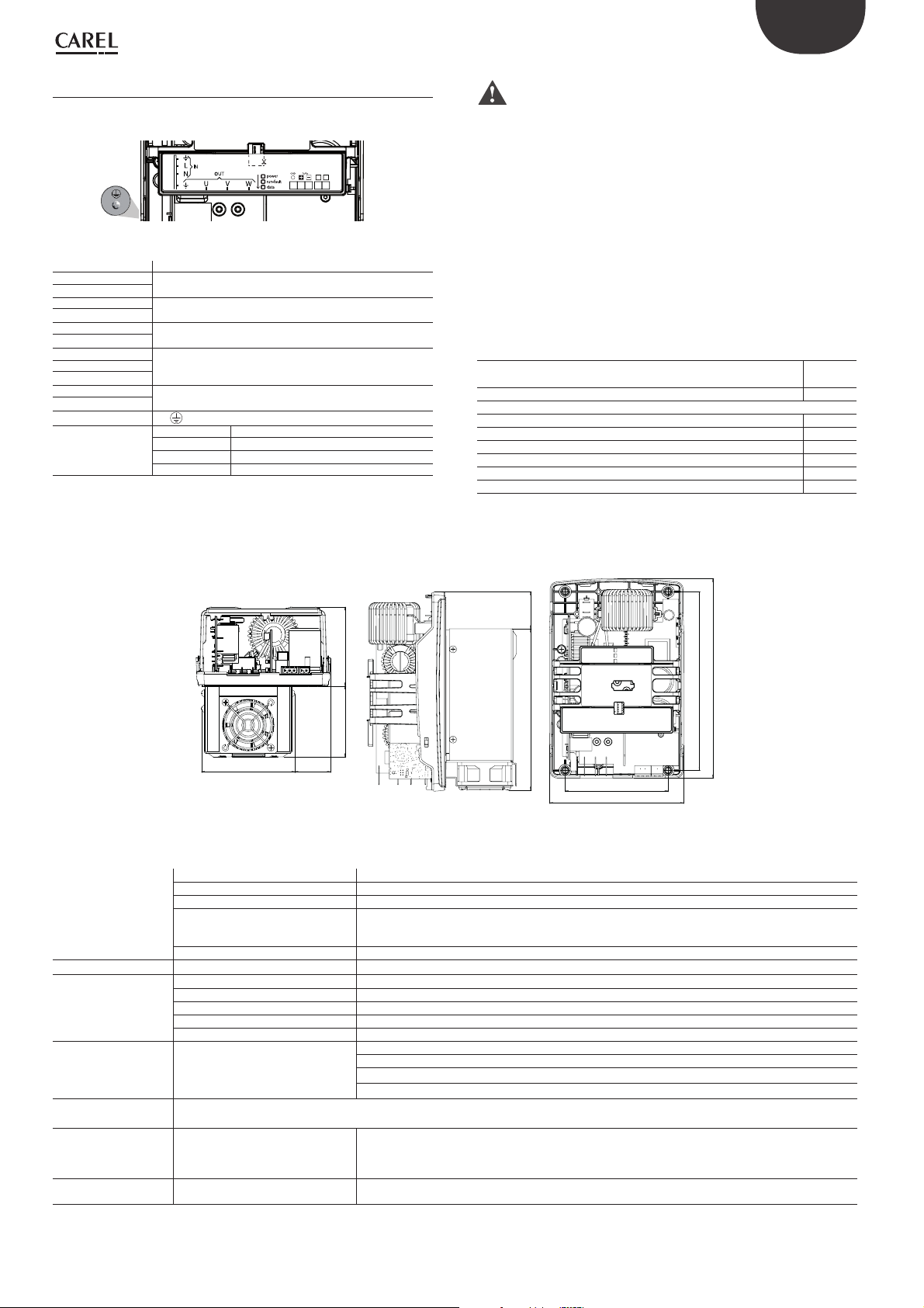
6.1 Unit ON/OFF
The unit can be switched on and off as follows:
• User terminal
• Supervisor
• Digital input
On-off from the user terminal and the confi guration parameters are
available under the main menu, branch Ac
On-off from the supervisor and from the digital input and start-up after a
blackout (with specifi c delay, to avoid continuous starts and stops in the
event of instability in the power supply) need be enabled.
On-off from the digital input is equivalent to an enabling signal, that is, if
the digital input is Off the unit cannot be switched on in any other way,
while if it is On, the unit can be switched on or off in any other way, with
the same priority (the most recent has precedence, whatever the origin),
as shown in the fi gure:
Digital Input
User interface
Supervisor
Unit On/O
Fig. 6.a
Note: certain special conditions or functions in the Hecu CO2
software require the unit to be powered off :
• Confi guration of certain parameters: e.g. inputs/outputs, confi guration
of compressors, inverter parameters.
• Installation of default parameters
• Manual management
Manual con guration
Hecu CO2 automatically downloads the optimised parameters for each
model of compressor at the end of the wizard procedure.
If the model of compressor is changed or the power+ is replaced, the new
system can be confi gured manually under Compressors Æ Advanced
Æscreen Cag01.
Hecu CO2 and power+ must be powered and connected via serial; the
address of power+ must be 1 (default).
The type of compressor is selected from the list of available compressors;
the number of motor poles and the correct model of power+ are defi ned
automatically.
Select YES for Set defaults and press ENTER.
If the model of power+ (as read by power+) is the same model or larger
than the power+ selected based on the type of BLDC compressor, the
default values can be written and Hecu CO2 can control the compressor.
Otherwise, the message "Not compatible" will be shown.
Envelope management
The envelope is the set of operating points in which a compressor can
operate safely for an indefi nite time. This can be represented graphically
by drawing the limits inside which the operating conditions must be
maintained. The fi gure shows the envelope for the Toshiba DY/RY series
compressors.
6.2 BLDC compressor
A maximum of 2 BLDC compressors can be managed using the Power+
inverter. The type of compressor is selected under Compressors Æ
Confi guration (Cag01).
The BLDC compressor is managed via Modbus and works only if
connected to a CAREL power+ inverter. If there is no communication
with the inverter, the compressor will not be able to operate.
Below is the list of compressors that are currently available:
Medium and low temperature with PSD1 (R744)
Compressor HPV RPRV Inverter Capacity
TOSHIBA DY30 E2V09CS1C0 E2V11CS1C0 PSD101021A 0.3 - 2.8 kW
TOSHIBA DY45 E2V11CS1C0 E2V14CS1C0 PSD1012200 0.5 - 4.2 kW
TOSHIBA DY67 E2V14CS1C0 E2V18CS1C0 PSD1016200 0.7 - 6.3 kW
TOSHIBA RY100 E2V18CS1C0 E2V24CS1C0 PSD1018400 1.0 - 8.8 kW
Medium and low temperature with PSD2 (R744)
Compressor HPV RPRV Inverter Capacity
TOSHIBA DY30 E2V09CS1C0 E2V11CS1C0 PS200122041*0 0.3 - 2.8 kW
TOSHIBA DY45 E2V11CS1C0 E2V14CS1C0 PS200122041*0 0.5 - 4.2 kW
TOSHIBA DY67 E2V14CS1C0 E2V18CS1C0 PS200152041*0 0.7 - 6.3 kW
TOSHIBA RY100 E2V18CS1C0 E2V24CS1C0 PS200184041*0 1.0 - 8.8 kW
* =0: no PEC version; * =1: PEC version
Note: go to ksa.carel.com to check the updated list of compressors
available, with reference to the “DC compressor availability table”
+050001835.
E2VSTA0310 unipolar stator Tevap. = -10°C
E2VSTA0310
unipolar stator
TGC = 32°C
Tab. 6.a
Tevap. = -10°C
TGC = 32°C
Tab. 6.b
Discharge
pressure
Pd max
Pd min
Ps min Ps max
Fig. 6.b
The envelope limits consist of:
Suction
pressure
• Minimum and maximum discharge pressure
• Minimum and maximum suction pressure
• Minimum and maximum compression ratio (CR)
• Maximum current drawn by the compressor
The operating conditions are defi ned by:
• Suction pressure
• Discharge pressure
• Discharge temperature
• Rotation speed (rps)
The maximum discharge pressure can be limited due to construction
requirements of the circuit; in this case, a limit will be applied to the
maximum discharge temperature. The shape of the envelope can change
as compressor speed varies, and with this the operating conditions that
are considered safe for the compressor. It is therefore possible that a
certain pair of operating pressures is considered safe (inside the envelope)
at a certain speed, and unsafe (outside of envelope) at another speed.
Hecu CO2 +0300085EN rel. 2.2 - 07.05.2019
22

ENG
If the operating conditions are close to the envelope limit or outside
of this, the controller applies corrective actions in an attempt to keep
the operating point inside the limits specifi ed by the manufacturer. It
is therefore possible that in such cases, the actual compressor speed
does not correspond to the cooling capacity request of the temperature
controller, that superheat is not maintained at the set point, or that the
discharge pressure is not kept at the optimal value. If the operating
conditions remain outside of the envelope for a time exceeding the alarm
threshold (screen Cag55, default 60 s), the compressor is stopped and an
out-of-envelope alarm is signalled.
3
2
9
Discharge pressure
1
8
5
6
7
Suction pressure
Fig. 6.c
The following zones are defi ned (see Figure 6.e):
1. Inside the envelope 6. Low compression ratio
2. High compression ratio 7. Low diff erential pressure
3. High discharge pressure 8. Low discharge pressure
5. High evaporation pressure 9. Low evaporation pressure
Compressor prevent function:
by managing the envelope, compressor "Prevent" actions can be applied
to attempt to avoid shutdown due to the high discharge pressure and
temperature thresholds.
The settings are made on the following screens:
Timers
The timers include a minimum On time, a minimum Off time and a
minimum time between two consecutive starts.
These parameters can be set on screen Caf35:
The logic is described in the following graph:
Comp
ON
OFF
min ON
time
min OFF
time
min time to start
same compressor
Fig. 6.d
time
10s
Force compressor OFF:
The compressor can be forced OFF if the suction pressure falls below the
threshold for a set delay time; these parameters are set on the following
screen:
Start-up
Hecu CO2 manages compressor start-up in the best way possible,
adapting operating speed so as to guarantee that the desired conditions
and excellent lubrication are reached very quickly.
For this reason, when starting the compressor is operated at a settable
fi xed speed (Cag52) for the minimum ON time, Fig. 6.c. During this stage,
the out-of-envelope alarm is disabled, but speed control remains active
if approaching or exceeding zone 2 (maximum compression ratio), 3
(maximum condensing pressure) or 4 (current limit).
The corresponding parameters are found under Compressors Æ
Advanced Æ screen Cag52:
23
Hecu CO2 +0300085EN rel. 2.2 - 07.05.2019

ENG
rps
Start-up
speed
min ON
time
min rps
Req
If after 15 seconds from when the compressor starts the pressure
diff erential is less than 0.2 barg above the value measured on starting,
Hecu CO2 stops the compressor and generates a "No compressor startup” alarm. This alarm is automatically reset and Hecu CO2 tries to start the
compressor fi ve times after a 30 second delay. After the fi fth attempt the
alarm is no longer automatically reset.
The corresponding parameters are found under Compressors Æ
Advanced Æ screens Cag50, Cag51:
Req = min rps
time
Fig. 6.e
If equalisation is based on the pressure diff erential (delta), the controller
measures the DeltaP between compressor suction and discharge
pressure. When the diff erential is below the value set on screen Cag49,
the compressor is enabled to start.
In the event of timed equalisation, the controller will not measure the
pressure diff erential but rather will enable the compressor to start after
a fi xed equalisation time, equal to the minimum compressor off time,
which can be set on screen Caf35.
Pressure di erential during start-up
The BLDC compressor cannot start if the pressure diff erential is greater
than a threshold defi ned by the compressor manufacturer. This limit
depends on the maximum current delivered by the inverter. As soon
as the pressure diff erential falls below the minimum threshold, the
compressor can start.
The corresponding parameters are found under Compressors Æ
Advanced Æ screen Cag49:
When the pressure diff erential is below 1 barg – 0.5 barg (fi xed value), the
compressor is ready to start.
Equalisation
Hecu CO2 makes it possible to equalise the pressure across the
compressor, simplifying condensing unit start-up. The equalisation mode
can be selected on screen Caf18: either "DELTA PRESSURE" or "TIME".
The valves used for equalisation and the percentage of opening to be
maintained during the procedure can be set on screen Caf19. For Hecu
CO2, the following valves can be selected: HPV, RPRV and bypass solenoid.
Hecu CO2 +0300085EN rel. 2.2 - 07.05.2019
24

After compressor start-up, a delay can be set on screen Caf32 for closing
the selected equalisation valves.
For the LT confi guration, LT compressor equalisation can only be
managed using the bypass solenoid valve.
ENG
Compressor crankcase heater:
Crankcase heating for BLDC compressors is required when the system is
being evacuated and oil lubrication is reduced due the presence of water
droplets, or when the compressor is off at low outside temperatures.
This function can be activated even without using an external heater,
but rather exploiting a special function implemented in the inverter that
controls the compressor.
The function is selected on the following screens:
DSH control
Hecu CO2 controls superheat on the compressor discharge line at the
same time as superheat on the suction line.
If suction superheat is less than 0K and discharge superheat is less than
10K, a countdown starts to set off the corresponding alarm (DSH Low
Liquid Flowback).
The alarm activation delay can be set on screen Cae41 and can be
diff erentiated for diff erent stages of operation: compressor start-up,
steady operation, defrost/washing active.
Vacuum function:
A manual procedure is available to evacuate the system; to do this, follow
the steps described in the Manual Management Branch (Bbdxx).
Screen Cag44 is used to deactivate the function based on the outside/
ambient temperature; if "COMP OFF" mode is selected on screen Cag43.
For Toshiba compressors, the recommended values to be set for
the Crankcase current (Cag43) must be between the minimum and
maximum values shown in the following table:
Compressor
model
Toshiba DY30 39 15 74 55
Toshiba DY45 39 15 74 55
Toshiba DY67 35 13 67 47
Toshiba RY100 24 15 46 55
(*) The crankcase current percentage value and the three-phase heat
generated in the motor windings (minimum and maximum) are
calculated at an ambient temperature of 25°C.
The current value to be applied can be adjusted depending on the
outside temperature, considering that it is not possible to exceed a
temperature of 55°C in the rotor windings when the unit is off .
Crankcase set
% (min)*
Winding heat
3PH [W]
Crankcase set
% (max)*
Winding heat
3PH [W]
Tab. 6.c
6.3 Compressor control
Control can be proportional or proportional + integral (P, P+I). The
corresponding parameters are found under Compressors Æ Control Æ
screen Cab14.
The set point is in the centre of the band. Proportional control is illustrated
in the following fi gure:
During this procedure, the compressor crankcase can be preheated
(see the crankcase heating function), however at the end the initial
confi guration needs to be reset, on screen Bbd03 or Cag43.
25
Regulation request
100%
Dierenziale
Setpoint
Regulation
probe value
Fig. 6.f
Hecu CO2 +0300085EN rel. 2.2 - 07.05.2019

ENG
With proportional + integral control, the integral time is summed to
the eff ect of proportional control, giving a null control error in steady
operation. This type of control is illustrated in the following fi gure:
Regulation
variable
The integral action depends on time and the deviation from the set point.
The integral time represents how fast integral control is implemented:
P+I
P
Setpoint
time
Fig. 6.g
• Low values bring fast actions yet more instability
• High values bring slower actions and more stability
The values should not be set too low, to avoid system instability.
Two types of control can be set, in loop
Compressors Æ Control Æ screen Cab01
• Fixed set point
• Floating set point
Floating set point
This software function is available by exploiting serial communication
with the evaporators. Serial communication allows information to be
exchanged in real time between the main Hecu CO2 controller and the
MPXPRO devices.
Hecu CO2 uses an advanced algorithm to adapt the condensing unit
suction pressure set point based on the request from each evaporator,
then weighing it according to evaporator capacity. Signifi cant variations
in request due to certain evaporator operating states, such as defrost, are
managed by Hecu, maintaining fi ne, stable control.
Suction
pressure
energy eciency
Fig. 6.h
The fl oating set point will then be managed using proportional + integral
control, the parameters of which can be set on screen Cab14.
Max Set point
Min Set point
time
Pumpdown
The compressor OFF function by pumpdown can be enabled on screen
Cag03. This function keeps the compressor on until the pumpdown
pressure threshold is reached, within the maximum time set on the same
screen.
Note: the MPXPRO controllers installed on the evaporators
implement the Smooth Lines function (see MPXPRO manual +0300055).
This function signifi cantly reduces the number of ON-OFF cycles in
traditional control by modulating the evaporator temperature using an
electronic expansion valve and adapting the superheat set point using
appropriate PI control based on the eff ective control temperature.
This function can be enabled and confi gured manually or automatically.
• The automatic procedure involves the Fast Commissioning operation
described in chapter 7, which automatically confi gures the control
parameters on both the condensing unit and the evaporators, using
the default values optimised by CAREL, yet amply modifi able.
• To confi gure the function manually, make sure that there is a serial
connection with the MPXPRO controllers on the evaporators, and
choose the type of control on screen Cab01. The Smooth Lines
function will then need to be confi gured on the MPXPRO controllers,
as described in the next chapter.
The unit fl oating suction pressure set point can vary between a settable
minimum and maximum value. The minimum and maximum limits for
the fl oating set point are shown on screen Cab04, in line with the limits
set on screen Cab02.
Low ambient (outside) temperature prevention:
This function prevents the unit from stopping due to low outside
temperatures.
The function can be activated if all of the following conditions are true:
1. Enabling selected
2. The evaporator request is greater than 0% (MPXPRO or ULTRACELLA
connected) or "Enable compressor from DI" is ACTIVE or the
diff erential pressure threshold (Prec - Psuc) is less than the set value
(default 2 bars).
3. The outside temperature is less than the value set (default -18°C)
4. The compressor request is = 0% and the compressor speed is = 0 for
longer than the set time (default 30 minutes)
The settings are made on the following screen
Hecu CO2 +0300085EN rel. 2.2 - 07.05.2019
When the function is activated:
1. The compressor set point is decreased by a settable value (default 8
bars) within the time set on the same screen
26

The function can be deactivated when at least one of the following
conditions is true:
1. Compressor control OFF
2. Active compressor alarms
3. The cut-off threshold has been reached (P suction < cut-off threshold)
4. The evaporator request is equal to 0% (from MPXPRO or ULTRACELLA)
or "Enable compressor from DI" is NOT ACTIVE (OFF due to control)
5. The compressor has been active for longer than a settable timeout
(default 10 minutes)
6. The suction pressure is greater than the operating set point
7. The outside temperature is greater than the set threshold (default
-18°C) + the diff erential (default 8°C) set on the following screen
ENG
DSS3: screen Fib04
Start the parallel compressor (L1) when starting the LT compressor (L2).
If NO is selected, the parallel compressor cannot start without a request.
When DSS1 is enabled, the following parameters remain hidden on
screen Fib04:
• Switch on period: 180s (hidden). During this period, the parallel
compressor request is forced to 50% to allow it to be started;
• Timeout: 180s (hidden). The LT compressor waits for the parallel
compressor to start, however is switched on in any case after the set
timeout has elapsed;
• Force off line 2 if line 1 is off : YES (hidden). The LT compressor (L2) is
switched off when the parallel compressor (L1) is switched off .
When DSS1 is NOT enabled, the following parameters can be modifi ed
on screen Fib04:
When the function is deactivated:
The compressor set point is reset to its normal value over a set time
(default 2 min, see time on screen Cad15).
6.4 Compressor management on LT units
(DSS and independent)
Management with DSS1 and DSS3
This involves synchronised management of the compressors. It
is recommended to activate both DSS1 and DSS3 so as to avoid
simultaneous compressor starts and optimise operation of the LT stage
in all operating conditions.
Below is a description of the functions that can be set:
DSS1: screen Fib02
This function prevents the two compressors from starting simultaneously.
Once the required percentage for activation has been reached, the LT
compressor waits for the parallel compressor to start, and then is turn
started after a set delay.
• Switch on period: 0-999s (def 180, this is the time that the parallel
compressor request is forced to 50% to allow it to start);
• Timeout: 0-999s (def. 180s; this is the time that the LT compressor waits
for the parallel compressor to start, after the set timeout it is switched
on in any case);
• Force off line 2 if line 1 is off : NO/YES.
• YES Æ forces the LT compressor off if the parallel compressor cannot
start.
• NO Æ forces the LT compressor off if there is an alarm on the parallel
compressor.
Independent management
Activating independent management on screen Fib05 automatically
disables DSS1 and DSS3, and the compressors can be switched on/off
independently, based on their own request. Some safety logic s also
guaranteed.
Below is a description of the functions that can be set.
By selecting YES, functions DSS1 and DSS3 are automatically disabled
and:
• the LT compressor can start even if activation of the parallel compressor
is NOT requested;
• the LT compressor cannot start if the parallel compressor is off due to
timing or alarms;
• the Parallel compressor is not activated if the LT compressor is not
operating (no LT required, LT compressor off due to timing or alarms).
27
Hecu CO2 +0300085EN rel. 2.2 - 07.05.2019

ENG
gg
Safety functions (active only if "Independent start of compressors" is set
to YES):
Par. start for high
rec. pressure:
Env. lim. for LT
high dis.
pressure:
LT cut-o thr. If
par. can’t start:
Force the parallel compressor on in the event of high
pressure in the receiver even if the LT compressor is switched
off due to no request or alarms (default threshold: 60 barg,
settable).
High pressure prevention based on the LT compressor envelope. Sets the condensing/discharge pressure limit at the
selected value, recommended threshold 45 barg (settable).
When the LT compressor discharge pressure exceeds the set
threshold, the controller begins to reduce compressor speed
in order to return to normal operating conditions (i.e. inside
the envelope). If the discharge pressure remains above the
set threshold, the compressor can be switched off due to the
envelope alarm (after the standard timeout for the envelope
alarm).
Threshold=0barg Æ function not active.
Cut-off due to LT compressor high pressure. The function is
activated when the parallel compressor is off due to timing or
alarms (default 50 barg, settable).
Tab. 6.d
Parallel compressor: oating set point
The receiver pressure and therefore the parallel compressor set point is
calculated according to the following relationship:
Fan operation with modulating device
If the fans are controlled by a modulating device, the meaning of the
parameters that associate the minimum and maximum values of the
device’s modulating output and the minimum and maximum capacity
of the modulating device on screens Dg01 and Dg02 is illustrated in the
following examples.
Example 1: minimum modulating output value 0 V, maximum value 10 V,
minimum modulating device capacity 0%, maximum value 100%.
Analog output
Max output
value = 10 V
Min output
value = 0 V
Min capacity = 0%
Set point
Dierential Dierential
Max capacity = 100%
Regulation
probe value
6.5 Fans
Hecu CO2 can manage up to two fans with a speed modulation device,
which may be an inverter or a PWM phase control device. In the same way
as for the compressors, fan control can be proportional or proportional
plus integral, based on pressure or temperature.
Fig. 6.i
Example 2: minimum modulating output value 0 V, maximum value 10 V,
minimum modulating device capacity 60 %, maximum value 100%.
Analog output
Max output
value = 10 V
Min output
value = 0 V
Min capacity = 60%
Set point
Dierential Dierential
Max capacity = 100%
Regulation
probe value
Fig. 6.j
Example 3: minimum modulating output value 2 V, maximum value 10 V,
minimum modulating device capacity 60 %, maximum value 100%.
Analog output
Max output
value = 10 V
Min capacity = 60%
Min output
value = 0 V
Set point
Dierential Dierential
Max capacity = 100%
Regulation
probe value
Hecu CO2 +0300085EN rel. 2.2 - 07.05.2019
Fig. 6.k
28

ENG
Cut-o
Hecu CO2 manages a cut-off control function for the fans; the function
can be enabled and the related parameters set in main menu branch
Db05. The operating principle of the cut-off function is shown in the
fi gure:
Regulation
request
Max
output value
Cut-O value
of request
Cut-O Set point Regulation Set point
Dierential Dierential
Max capacity = 100%
Regulation
probe value
Fig. 6.l
A percentage of the control request and a cut-off set point can be set.
When the control request reaches the set cut-off value, this value is kept
constant until the control value falls below the cut-off set point, after
which it falls to 0 % and remains there until the request exceeds the cutoff value again.
Fans with compressor OFF
The fans can be stopped after a delay from when the compressor is
switched OFF. Furthermore, they can be restarted before the compressor
starts, when the request is increasing. These settings are made on screen
Db04.
Floating
setpoint
Setpoint
oset
Min
external temperature
time
Fig. 6.m
6.6 Oil management
Oil injection
Oil return is a critical factor when using BLDC compressors. Hecu CO2
can manage three diff erent solutions for injecting return oil to the
compressor. The related confi gurations can be set on screen Fab15.
Capillary valve
The simplest solution is to use a capillary valve, with fi xed opening,
calibrated based on rated conditions. This solution however creates
ineffi ciencies, by injecting or less oil than required by the compressor.
standard
oil separator
1
BLDC
compressor
Speed up
Hecu CO2 can manage the speed up function, used to overcome the
initial inertia of the fans. The function can be enabled and the related
parameters set in main menu branch Dg13.
If speed up is enabled, a start time can be set in which the fan speed is
forced to 100%. If the outside temperature sensor is used, moreover, a
threshold can be set (with reset diff erential) below which speed up is
disabled, so as to not drastically lower the condensing pressure at startup.
Floating condensing pressure set point
For the condenser line, the fl oating set point enabled on screen Dd05)
is based on the outside temperature. The fl oating condensing pressure
set point is achieved by adding a constant programmable value to the
outside temperature and limiting the resulting value between a settable
minimum (Db02) and the set point defi ned on screen Dd06, as shown
in the fi gure:
capillary
Fig. 6.n
Electronic expansion valve (EEV COMP SPEED)
This solution involves a CAREL expansion valve. Valve opening is
calibrated based on the BLDC compressor operating conditions, adjusted
proportionally based on compressor speed.
A standard oil separator can be installed to exploit this function. The
control algorithm is represented in the following graph, and the
parameters can be confi gured on screen Fab18.
standard
oil separator
EEV valve
4
V
BLDC
compressor
Fig. 6.o
Opening valve (%)
Max open. valve
29
Min open. valve
Min Speed Max speed
Fig. 6.p
Hecu CO2 +0300085EN rel. 2.2 - 07.05.2019
Compressor
Speed (lps)

ENG
Electronic expansion valve (EEV LEVEL MNG)
This solution involves a CAREL expansion valve. The valve opening is
calibrated based on normal system operating conditions. This solution is
very effi cient from an energy viewpoint, as it injects the exact quantity of
oil needed by the compressor. In order to use this function, an advanced
oil separator needs to be installed, featuring a level sensor that defi nes
three states via two digital inputs, confi gurable on screens Faa55, Faa56.
An advanced algorithm calculates valve opening based on the time that
elapses between the various states, comparing this against the previous
measurements. The objective is to replicate the oil level inside the
compressor by measuring the amount in the separator and keeping this
level stable over time.
advanced
oil separator
(double oil level)
EEV valve
3
V
BLDC
compressor
Fig. 6.q
On screen Fab20, two preventive thresholds can be set for the high and
low oil level (Emergency HL and LL). If the oil remains at this level for
the set time, the valve will open to the maximum (HL) or minimum (LL),
moving at 1 step/sec.
Electronic expansion valve controlled by external driver (EEV
COMP SPEED)
This solution features an expansion valve driven by an external driver
(EVDevo, EVD mini), confi gured as a positioner that receives the 0...10 V
control signal from the Hecu unit.
This is exploited when integrated drivers for the oil valve cannot be used
on Hecu CO2 as they are reserved for transcritical valves. Valve opening
is calibrated based on the BLDC compressor operating conditions (MT
or LT, not parallel), adjusted proportionally based on compressor speed.
A standard oil separator can be installed to exploit this function.
The parameters can be confi gured from screens Bad14 for assigning the
analogue output, and Fab15 to enablòe the function.
rps
Speed Force
Thr di.
Speed Thr
Act. Delay Force time
Comp. Speed
t
t
Fig. 6.s
Oil Recovery Washing
Another function available on Hecu CO2 to assist oil return to the
compressor involves washing the evaporators. This function uses serial
communication between Hecu CO2 and the MPXPRO controllers,
and the electronic expansion valves on the evaporators. The oil
recovery washing function sets the superheat set point to 0K for a
settable time t1 [default 3 minutes] in order to retrieve the oil spread
along the refrigerant circuit; the valve will thus open further, “washing”
the evaporator and fl ushing the accumulated oil back the compressor.
standard
oil separator
V
BLDC
compressor
EEV valve
Fig. 6.r
Oil speed boost
This function boosts the return of oil by operating the compressor at
a fi xed speed for a set time, thus recovering the oil spread along the
refrigerant circuit.
This override function is activated if the following conditions are true, see
screens Fab15, Fab23:
• Speed boost: YES
• Compressor speed < minimum threshold
• The previous conditions remain for a set time
Hecu CO2 +0300085EN rel. 2.2 - 07.05.2019
Note: to make this function more eff ective, the electronic expansion
valve on the evaporator opens fully at the start of the recovery washing
cycle and then its position is controlled automatically based on the new
superheat set point.
td is the time at the end of a washing cycle for which compressor speed
remains fi xed, and valve opening returns to the same position as prior
to activation of the function [default 2 minutes]. If this value is set to 0,
at the end of a washing cycle the system will restart without overriding
compressor speed and keeping the valve at the previous opening
position for a set time. During a washing cycle, the following conditions
are set:
• Oil recovery washing: ON
• Smooth Line: OFF
• P3: 0K
• P7: -10K
• St: -50°C
30

ENG
The following diagram explains operation and control of the electronic
expansion valve and the superheat set point:
Cmp speed
EEV Max opening
EEV position
Cabinet SH
Cabinet SH
setpoint OK
C1 Washing
C2 Washing
C3 Washing
ON
OFF
ON
OFF
ON
OFF
t1
Legende:
t1= time ON td= Fixing time function
t1 t1
td td td
t
t
t
t
t
t
Fig. 6.t
Washing of individual cabinets can be confi gured exclusively in sequential
mode.
Then select the digital output on screen Faa68.
The DO will be used by third-party controllers (evaporators) to activate
cabinet set point compensation: for example, from 5°C to -50°C. This
action will open the expansion valve and at the same time the superheat
control will remain active to avoid the return of liquid on the unit’s suction
line. The number of wash cycles is selected on the following screen.
Note: this function will be less eff ective than the one Carel provides
via serial connection of the evaporators managed by MPXPRO and
UltraCella controllers.
tON is the duration of each single washing cycle. “N. of washing per day in
each evap.” is the number of washing cycles per day for each evaporator.
Fixing time is the transition time at the end of each single washing cycle
to keep the system in stable conditions.
If using evaporators managed by non-Carel controllers (third party
devices), a digital output can be used, as described in the following
paragraph.
Digital output for cabinet washing
The purpose of this function is to exploit the "Hecu wash" function to
enable a digital output that can be used to "wash" evaporators with thirdparty controllers.
To activate this function, the evaporators with MPX/UltraCella
controllers must not be enabled, then on screen Fab15 enable the
washing cycles as shown below:
Compressor “ready” digital output
On screen Baccm, a digital output can be selected that is activated when
the compressor is "ready". This means that it is able to deliver its cooling
capacity.
On stand-alone units, this can be used as a "control" digital input on the
cabinets to improve control/synchronization between the condensing
unit and the evaporators.
The function is NOT active when:
• The compressor is off due to timers (minimum Off time or timer
between starts)
• The compressor is off due to cut-off
• On LT units, if the compressor is off due to the DSS function
• The compressor is off due to an alarm, with the following exceptions
(to prevent the unit from shutting down):
– Low suction pressure alarm
– Low SH
31
Hecu CO2 +0300085EN rel. 2.2 - 07.05.2019

ENG
Evaporator requests
To roughly synchronise the condenser unit with evaporators managed by
third-party controllers (for example, when defrosting),
a digital input can be confi gured (on screen Baadh). This means that the
compressor does not start until the DI is activated, even if the suction
pressure is higher than the set point.
The DI is confi gured on the following screen:
Screen Baadh
6.7 HPV valve management
Management of the HPV valves, which separates the high pressure part of
the system from the medium pressure part, determines the transcritical
and subcritical operating mode of the unit. In transcritical mode, the
valve is controlled so as to obtain maximum effi ciency, while in subcritical
mode subcooling is controlled.
The HPV valve has proportional + integral (PI) control, with the set point
based on an optimal gas cooler pressure value calculated using the gas
cooler pressure and temperature, as described below. Enabling HPV
valve management means also enabling system transcritical mode.
The HPV valve can be managed directly by Hecu CO2 via the driver
integrated into the controller. The algorithm for calculating the HPV valve
control set point can be optimised or customised by the user, using the
parameter settings.
Optimised set point calculation
The optimised set point is calculated as shown in the fi gure.
P₁₀₀
%
P
max
Pressure (Bar)
HPV OPENING ZONE
UPPER PROPORTIONAL ZONE
T₂₃
C
LOWER PROPORTIONAL ZONE
%
min
₁₀₀
T
T
D
A
TRANSCRITICAL ZONE
T₁₂
B
INTERMEDIATE ZONE
SUBCRITICAL ZONE
pressures at the limit of the transcritical and subcritical zones. This area
has the purpose of avoiding discontinuity in the transition between
the two zones.
• Upper proportional zone, defi ned by P
works with proportional control only between the opening reached
at pressure P
pressure decreases, the opening of the HPV valve remains constant
and the maximum opening at pressure P
max
< Pgc < P
max
: the valve
100%
100%
. If the
until it returns into the transcritical zone, where control resumes as
described previously.
• Lower proportional zone, defi ned by T
with proportional control only between the opening reached at
temperature T
the pressure increases, the opening of the HPV valve remains constant
and the maximum opening at temperature T
min
100%
< Tgc < T
: the valve works
min
100%
. If
until it returns into the subcritical zone, where control resumes as
described above. This operating mode can be disabled by parameter.
Custom set point calculation
The custom set point diff ers from optimised control in that the curve
in the subcritical phase is a straight line and is defi ned by the user, and
therefore the bands and the set point can be customised by the user.
The behaviour in the remaining bands is as described for the optimised
algorithm.
HPV valve auxiliary functions
HPV valve management includes some auxiliary functions:
• Pre-positioning: when switching the unit ON, the HPV valve remains
in a fi xed position set by parameter for a set time, so as to be able
to quickly increase the pressure in the receiver. This procedure is
reactivated whenever the unit switches OFF or the HPV valve is reset to
the minimum position when all of the compressors stop (opt.).
• Close valve with compressors o : if all of the medium temperature
compressors are switched off , the HPV valve can move to the
minimum opening when OFF, which can be set by parameter. When
a compressor restarts, valve control resumes, with the pre-positioning
procedure described in the previous point.
• Minimum and maximum opening values: the minimum opening
when OFF (from keypad, digital input or supervisor) and when ON can
be diff erentiated, while there is only one maximum opening value.
• Maximum percentage variation: the valve movement cannot exceed
the set maximum percentage variation per second.
• Set point lter: the HPV valve control set point is calculated taking into
account the average of the last n samples (maximum 99), so as to avoid
sudden variations due to the high variability of the gas cooler outlet
temperature.
• Minimum set point: a minimum value can be set for the HPV valve set
point; the set point can never fall below this value, regardless of the
parameters entered, so as to protect the compressors.
• Set point deviation alarm: if the gas cooler pressure remains too far
away from the calculated set point for too long (settable threshold and
delay), an alarm can be signalled.
HPV CLOSING ZONE
Enthalpy (KJ/Kg)
Fig. 6.u
The HPV valve is managed according to the area identifi ed, based on the
gas cooler outlet temperature and pressure values. To defi ne the zones,
the two pressure values P
relative to points B and C in the fi gure, and the two temperatures T
T
need to be set. In the following diagram, Tgc and Pgc refer to the gas
100%
cooler temperature and pressure.
100%
and P
, the two temperatures T12, T23
max
min
and
The behaviour of the HPV valve in the diff erent zones is as follows:
• Transcritical zone, identifi ed by T
works with proportional + integral (PI) control so as to maintain the
maximum COP, determined by the optimal pressure P
a function of the gas cooler outlet temperature T
• Subcritical zone, identifi ed by T
control so as to keep subcooling constant.
• Transition zone, identifi ed by T
control, with a pressure set point identifi ed as the intersection of the
≥ T12 and Pgc ≤ P
gc
≤ Tgc ≤ T23: the valve works with PI
min
≤ Tgc ≤ T12: the valve works with PI
23
ogc
max
calculated as
opt
.
: the valve
two points B and C in the fi gure, obtained by calculating the optimal
Hecu CO2 +0300085EN rel. 2.2 - 07.05.2019
Receiver pressure control using the HPV valve
If the receiver pressure falls below the set minimum operating pressure
threshold, the dynamic set point calculated for the HPV valve can be
adjusted, so as to increase the pressure inside the receiver. An off set
proportional to the deviation from the minimum threshold is subtracted
from the calculated set point, so that opening the HPV valve further
increases the pressure in the receiver. The off set is directly proportional
to the deviation from the minimum operating threshold, as shown in the
fi gure:
Setpoint HPV
OFF. MAX
Pmin Prec min
Fig. 6.y
32

ENG
Vice-versa, if the receiver pressure rises above the set maximum operating
pressure threshold, the dynamic set point calculated for the HPV valve
can be adjusted, so as to decrease the pressure inside the receiver.
An off set proportional to the deviation from the maximum threshold is
added to the calculated set point, so that closing the HPV valve further
decreases the pressure in the receiver.
The off set is directly proportional to the deviation from the maximum
operating threshold, as shown in the fi gure:
Setpoint HPV
OFFS
P
REC PREC
Fig. 6.v
max
Summary of HPV valve inputs, outputs and parameters
Below is a summary of the inputs/outputs and parameters used, together
with the corresponding confi guration screens. For details, see Appendix
A.1.
Summary
Analogue inputs Bab07,
Digital inputs Baade,
Analogue outputs
Digital outputs --- --Parameters
Set Fhb01 Enable HPV valve management, i.e. enable tran-
Defi nition
of the zones
Parameters
Control Fhb08 Proportional gain for proportional + integral HPV
of HPV valve inputs, outputs and parameters
Screen Description
Da39
Bab10 Gas cooler outlet temperature
Bab09,
Da40
Bab15 Backup outside temperature
Fha04
Bad02,
Fha06
Fhb05-06 P
Fhb07 T
Gas cooler pressure
Gas cooler backup pressure
HPV valve alarm
Valve HPV output
scritical operating mode
Select the type of algorithm to be applied for
calculating the pressure set point
upper pressure limit
100%
pressure for the defi nition of the upper
P
max
proportional zone
P
optimum pressure calculated at the transition
critic
temperature between the intermediate zone and
the transcritical zone
T
limit temperature between transcritical zone
12
and intermediate zone
T
limit temperature between intermediate zone
23
and subcritical zone
temperature for the defi nition of the lower
T
min
proportional zone
temperature for the defi nition of the valve
100%
complete opening zone
Subcooling delta for optimised control
Coeffi cient for determining the custom curve
valve control
Integral time for proportional + integral HPV valve
control
Safety features Fhb02 Minimum HPV valve opening with unit ON
Safety features Fhb18 HPV valve closing enabled when all line 1 com-
Screen Description
Fhb04 HPV valve opening at start-up during pre-posi-
Fhb09 Enable fi lter action on HPV valve set point
Fhb13 HPV valve safety position
Fhb14 Off set to be applied to the outside temperature in
Fhb15 Enable HPV valve safety procedures
Fhb16 High receiver pressure threshold
Fhb17 Low receiver pressure threshold
Fhb20 Enable the warning function when the gas cooler
Fhb03 Maximum HPV valve opening
Fhb30 Maximum HPV valve control set point
Fhb10 Minimum HPV valve control set point
Minimum HPV valve opening with unit OFF
tioning
Pre-positioning duration
Number of samples
the event of a gas cooler temperature probe error
Maximum receiver pressure allowed
Maximum off set to be added to the HPV set point
when the receiver pressure exceeds the high
pressure threshold
Minimum receiver pressure allowed
Maximum off set to be subtracted from the HPV
set point when the receiver pressure falls below
the low pressure threshold
pressors are off
HPV valve closing delay when all line 1 compres-
sors are off
pressure is too far away from the set point for the
set time
Diff erence between gas cooler pressure and set
point to generate the warning
Delay time before generating the warning
Maximum variation per second allowed for HPV
valve output
Enable valve position (delay threshold)
Enable low temperature control (lower proportional zone)
Tab. 6.e
6.8 RPRV valve management
The RPRV valve is managed with PI control so as to keep the pressure
inside the CO
The RPRV valve can be managed directly by Hecu CO2 via the driver
integrated into the controller.
RPRV valve auxiliary functions
RPRV valve management includes some auxiliary functions:
• Pre-positioning: when switching the unit ON, the RPRV valve remains
in a fi xed position set by parameter for a set time, so as to be able
to quickly increase the pressure in the receiver. This procedure is
reactivated whenever the unit switches OFF or the RPRV valve is reset
to the minimum position when all of the compressors stop.
• Close valve with compressors o : if all of the medium temperature
compressors are switched off , the RPRV valve can move to the
minimum opening when ON, which can be set by parameter. When
a compressor restarts, valve control resumes, with the pre-positioning
procedure described in the previous point.
• Minimum and maximum opening values: the minimum opening
when OFF (from keypad, digital input or supervisor) and when ON can
be diff erentiated, while there is only one maximum opening value.
• Maximum percentage variation: the valve movement cannot exceed
the set maximum percentage variation per second.
• Maximum receiver pressure: a maximum value can be set for the
receiver pressure, beyond which an alarm is signalled and the unit can
be shutdown. Shutdown is optional and can be enabled by parameter.
receiver at the set point.
2
Summary of RPRV valve inputs, outputs and parameters
Below is a summary of the inputs/outputs and parameters used, together
with the corresponding confi guration screens. For details, see chapter 6
and Appendix A.1.
33
Hecu CO2 +0300085EN rel. 2.2 - 07.05.2019

ENG
Summary of RPRV valve inputs/outputs and parameters
Analogue inputs Bab66,
Digital inputs Baadf,
Analogue outputs Bad03,
Digital outputs --- ---
Parameters
Set Fhb21 Enable RPRV valve management
Control Fhb25 CO
Parameters
Safety features Fhb22 Minimum RPRV valve opening with unit ON
Screen Description
Fha01
Fha05
Fha07
Fhb23 RPRV valve opening at start-up during pre-po-
Fhb24 Maximum RPRV valve opening
Fhb26 HPV valve safety position
Fhb27 RPRV valve closing enabled when all line 1
Fhb28 High receiver pressure alarm threshold
Fhb31 Maximum RPRV valve control set point
RPRV receiver pressure probe
RPRV valve alarm
RPRV valve output
receiver pressure set point
2
Proportional gain for proportional + integral
RPRV valve control
Integral time for proportional + integral RPRV
valve control
Minimum RPRV valve opening with unit OFF
sitioning
Pre-positioning duration
Maximum variation per second allowed for RPRV
valve output
compressors are off
RPRV valve closing delay when all line 1 com-
pressors are off
High receiver pressure alarm diff erential
High receiver pressure alarm delay
Type of high receiver pressure alarm reset
Enable compressor shutdown with receiver high
pressure alarm
Enable valve position (delay threshold)
Tab. 6.f
6.9 Generic functions
Hecu CO2 can use the free inputs / outputs and certain internal variables
for a number of generic functions.
The following generic functions are available for each board:
• 5 stages
• 2 modulation functions
• 2 alarms
Each function can be enabled/disabled by digital input and on the
user interface. The generic functions can be enabled and the related
parameters set in main menu branch Ff To be able to use the free inputs,
these fi rst need to be confi gured as generic from probes A to E (analogue
inputs) and general inputs from F to J (digital inputs), consequently a
maximum of fi ve analogue inputs and fi ve digital inputs can be used.
After having confi gured the generic probes, the associated variables
can be used as control variables, and the digital inputs as variables for
enabling the functions. As well as the generic probes and inputs, other
internal variables in the Hecu CO2 software can be used, depending on
system confi guration.
Examples:
for analogue variables:
• Suction pressure
• Condensing pressure
• Saturated suction temperature
• Saturated condensing temperature
• Suction temperature
• Discharge temperature
• % of compressors on
• % of fans on
• Superheat
• Subcooling
• Liquid temperature
• % of compressor request
• % of fan request
for digital variables:
• High suction pressure alarm
• Low suction pressure alarm
• High condensing pressure alarm
• Heartbeat
Each generic function can be assigned a unit of measure and a description.
Below are descriptions of how the three types of generic functions work.
Stages
Hecu CO2 can manage up to fi ve stage functions, with either direct or
reverse operation. In both cases, a set point and a diff erential can be
defi ned; operation of the corresponding output is shown in the fi gure
below, for both cases:
Direct stage
Di. Di.
Setpoint
Reverse stage
Di. Di.
Setpoint
Regulation
variable
Regulation
variable
Fig. 6.w
If a variable has been set to enable the function, the output connected to
the stage will be active when the enabling variable is active.
For each stage, there is a high alarm threshold and a low alarm threshold,
both absolute values. For each alarm, the activation delay and priority can
be confi gured.
Modulation
Hecu CO2 can manage two modulation functions, with either direct or
reverse operation. In both cases, a set point and a diff erential can be
defi ned; operation of the corresponding output is shown in the fi gure for
direct operation, with the cut-off function also enabled:
Direct modulation
Max
Min
(Cut-o
Value)
Setpoint
Hyster.
Dierential
Regulation
variable
Fig. 6.x
If a variable has been set to enable the function, the output connected
to the stage will be active when the enabling variable is active. For each
modulation function, there is a high alarm threshold and a low alarm
threshold, both absolute values. For each alarm, the activation delay
and priority can be confi gured. A minimum and maximum value of the
modulation output can also be set, and the cut-off function enabled,
which works as shown in the previous fi gure.
Alarms
Hecu CO2 can manage two alarm functions, by confi guring the digital
variable to be monitored, the activation delay, the priority and an
optional description. Each generic alarm function can be associated with
a digital output for activating external devices when the alarm occurs.
One example of a generic alarm functions is detecting gas leaks.
Hecu CO2 +0300085EN rel. 2.2 - 07.05.2019
34

6.10 Default value management
Hecu CO2 can manage two diff erent sets of default values:
• user defaults
• Carel defaults
Either of the two sets can be activated from the main menu branch I.d.
Important: after having reset the default values, the Hecu CO2
board needs to be powered off and on again.
Saving and restoring user default values
Hecu CO2 can save on the controller the exact confi guration set by the
user and then reload it at any time.
All of the set values are saved, therefore loading the user defaults restores
the exact same conditions of the Hecu CO2 controller at the moment the
values were saved.
Note: only one user default confi guration can be saved, therefore if
saving the values another time, the new values overwrite the previous
ones.
Important:
• the procedure for resetting the Carel default values involves clearing
the Hecu permanent memory, therefore the operation is irreversible;
• the user values cannot be reloaded if updating the Hecu software; for
further details please see Chap. 9, which describes how to save the
parameters for diff erent versions of the software.
ENG
Loading the Carel default values
The values pre-defi ned by Carel can be loaded at any time, restoring
the Hecu CO2 default settings, and therefore repeating the start-up
procedure described previously.
Important: he procedure for resetting the Carel default values
involves clearing the Hecu permanent memory, therefore the operation
is irreversible.
Note: to repeat the Wizard, the Carel default values fi rst need to be
reset.
35
Hecu CO2 +0300085EN rel. 2.2 - 07.05.2019

ENG
7. FAST COMMISSIONING
Once the condensing unit has been confi gured, the MPXPRO/UltraCella
controllers installed on the evaporators then need to be confi gured, and
subsequently the entire system representing the combination of both.
The Fast Commissioning function is an automatic procedure that assists
the installer in the fi nal confi guration of the entire system: condensing
unit connected via serial with up to fi ve MPXPRO/UltraCella controllers,
as described in par. 7.4.
7.1 MPXPRO con guration
(SW version ≥ 4.0)
General connection diagram
It is recommended to follow the general connection diagram shown
here, so as to simplify the subsequent controller confi guration stage by
exploiting many of the pre-defi ned parameters.
Power Supply
AC 115-230 V
200 mA max
LN
AUX4
NO NC CNLCNO
R1 R5R2 R3 R4
AUX3
(
(
NO NC NCC NO C
AUX1
(
(
AUX2
(
(
NCNO C
N
L
Warning: Before making any operation on
the control board, turn off the supply mains
turning off the main switch of the
electrical panel.
The contemporary operation of both
outputs is not granted with any
actuator. Please refer to the technical
features.
AC 115-230 V
200 mA max
- 0 to10 Vdc Analog output MX3OPA10**
Expansion board:
- PWM driver MX3OPPWM**
2
- E
V driver MX3OPSTP**
MPX PRO
S5/DI2 S6/DI3 S7/DI4
S2S1 S3
NTC NTC NTC NTC
Probe (sd)
probe (sm)
Air off temperature
Defrost temperature
S4/DI1
GND
Probe (sr)
Air on temperature
Superheated gas
Probe (tgs)
GND 5Vdc
RATIOMETRIC
Probe (peu/teu)
Pressure/temperature
Saturated evaporation
Once the wiring has been completed, simply follow the wizard that is
displayed when the MPXPRO devices are switched on for the fi rst time.
Details of this procedure are shown below; for further information see the
MPXPRO manual + +0300055EN rel. 1.4 of 16/02/2015..
T.U.I.
VLGNDDI5
Tx/Rx
tLAN
remote infrared
IRTRMPX000
Fig. 7.a
R=
20 mA max totally
470 Ω
MCHRTF
LOAD 1
LOAD 2
SSR1
PWM modulating fans
Trim heater
M.S.N.
Tx/Rx
GND
Tx/Rx+
Tx/Rx-
Supervisor
RS485
12 VPWM1PWM2
Shield
Connection:
IR*U*
AUX
Gnd
Power
Supply
Rx/Tx
1 2 3
VL (25) GND (26)
T.U.I.
Tx/Rx (24)
Power Supply
GND
Rx/Tx
IR*X*
AUX
GND
(see the technical
leaflets +050000135)
Important: in order to confi gure the entire system, fi rst check that
the cabinets are equipped with MPXPRO controllers and the
corresponding EEV electronic expansion valve module.
Hecu CO2 +0300085EN rel. 2.2 - 07.05.2019
36

ENG
Guided commissioning procedure
When fi rst started, MPXPRO opens a guided procedure that helps the
user set the main parameters for the confi guration of the electronic valve
and the serial network.
Commissioning parameters
Par. Description
/P2 Type of probe, group 2 (S4, S5)
/P3 Type of probe, group 3 (S6)
/Fd Assign tGS (superheated gas temperature probe)
/FE Assign PEu/tEu (saturated evaporation pressure/temperature probe)
/U6 Maximum value of probe 6
/L6 Minimum value of probe 6
P1 Electronic valve
PH Type of refrigerant
In Type of unit
Sn Number of slaves in the local network
H0 Serial or Master Slave network address
Tab. 7.a
The parameters can be set from the user terminal or the remote control.
If using the remote control, a terminal with display and infrared (IR) port
is required.
After powering on the controller:
1. the fi rst parameter is displayed: /P2 = type of probe, group 2 (S4, S5)
2. press Set to display the parameter value;
3. press UP/DOWN to modify the value;
4. press Set to confi rm, the “spanner” icon is no longer shown, indicating
that the setting has been performed;
5. press UP and repeat steps 2, 3 & 4 for the subsequent parameters; /P3, /Fd,
/FE, /U6, /L6, P1, PH, In, Sn, H0;
6. press Prg/mute for 5 s to exit the guided commissioning procedure.
/Fd: Assign tGS (superheated gas temperature probe)
This is used to assign the measurement of the superheated gas
temperature at the evaporator outlet to the selected probe.
Par. Description Def Min Max UOM
/Fd Assign tGS (superheated gas temperature)
0 = Function
disabled
1 = Probe S1 7 = Probe S7
2 = Probe S2 8 = Serial probe S8
3 = Probe S3 9 = Serial probe S9
4 = Probe S4 10 = Serial probe S10
5 = Probe S5 11 = Serial probe S11
6 = Probe S6
0 0 11 -
Tab. 7.d
/FE: Assign PEu/tEu (saturated evaporation pressure/temperature
probe)
Assigns the probe used to measure the saturated evaporation pressure/
temperature, which by default is the probe connected to input S6. It is
recommended to use the 0 to 5 Vdc ratiometric probe.
Par. Description Def Min Max UOM
/FE Assign PEu/tEu (saturated evaporation pressure/
temperature probe). See /Fd
0 0 11 -
Tab. 7.e
/U6, /L6: Maximum/minimum value of probe S6
Parameters /L6 and /U6 are used to set the maximum and minimum
limits for the range of measurement of the probe connected to input S6.
Par. Description Def Min Max UOM
/U6 Maximum value of probe 6 9.3 /L6 160 barg, RH%
/L6 Minimum value of probe 6 -1.0 -20 /U6 barg, RH%
Tab. 7.f
MPXPRO
Fig. 7.r
/P2: Type of probe, group 2 (S4, S5)
This is used to select the type of temperature probe to be used for inputs
S4 and S5.
Par. Description Def Min Max UOM
/P2 Type of probe, group 2 (S4, S5)
0 = NTC Standard Range –50T90 °C
1 = PTC Standard Range –50T150 °C
2 = PT1000 Standard Range –50T150 °C
3 = NTC L243 Standard Range –50T90 °C
003-
Tab. 7.b
Note: the NTC L243/PTC/PT1000 probes can only be confi gured on
the full optional models or with EEV driver. To assign the functions
of the other probes, see parameters /FA, /Fb, /Fc, /Fd, /FE,
/FF, /FG, /FH, /FI, /FL, /FM. For calibration, see parameters /c4, /c5.
/P3: Type of probe, group 3 (S6)
Selects the type of temperature or ratiometric pressure probe for input
S6.
Par. Description Def Min Max UOM
/P3 Type of probe, group 3 (S6)
0 = NTC Standard Range –50T90 °C
1 = PTC Standard Range –50T150 °C
2 = PT1000 Standard Range –50T150 °C
3 = NTC L243 Standard Range –50T90 °C
4 = 0 to 5 V ratiometric probe
004-
Tab. 7.c
P1: Type of electronic expansion valve
MPXPRO can control the CAREL E2V electronic expansion valve.
The CAREL electronic expansion valve is required for the Hecu CO2, and
therefore this parameter must always be set to “2”.
Par. Description Def Min Max UOM
P1 Electronic valve
0 = not present
1 = PWM valve
2 = CAREL E
2
V valve
002-
Tab. 7.g
PH: Type of refrigerant
The type of refrigerant is essential for calculating the superheat value.
In addition, it is used to calculate the evaporation and condensing
temperature based on the pressure probe reading. The following table
shows the refrigerants that are allowed and corresponding compatibility
with the CAREL E
2
V valve. In this case, the value must be set for CO2, i.e.
PH=11.
Par. Description Def Min Max
PH Type of refrigerant
3025
0 = Custom gas 13 = R1270
1 = R22 14 = R417A
2 = R134a 15= R422D
3 = R404A 16= R413A
4 = R407C 17= R422A
5 = R410A 18= R423A
6 = R507A 19= R407A
7 = R290 20= R427A
8 = R600 21= R245Fa
9 = R600a 22= R407F
10 = R717 23 = R32
11 = R744 24 = HTR01
12 = R728 25 = HTR02
Tab. 7.h
Note: the NTC L243/PTC/PT1000 probes can only be confi gured on
the full optional models or with EEV driver.
37
Hecu CO2 +0300085EN rel. 2.2 - 07.05.2019

ENG
In: Type of unit
This parameter In assigns the function of Master or Slave to the controller.
Hecu CO2 only accepts MPXPRO master controllers, therefore this
parameter must always be set to “1”.
Par. Description Def Min Max UOM
In Type of unit: 0 = Slave; 1 = Master 0 0 1 -
Tab. 7.a
Sn: Number of slaves in the local network
This parameter tells the Master controller how many Slave controllers it
needs to manage in the local network. Hecu CO2 only accepts MPXPRO
master controllers, therefore this parameter must always be set to “0”.
Par. Description Def Min Max UOM
Sn Number of slaves in the local network
005-
0 = no Slaves
Tab. 7.b
7.2 Ultracell con guration
(SW version ≥ 2.0)
General connection diagram
H0: Serial or Master Slave network address
Parameter H0 indicates the MPXPRO serial address.
Par. Description Def Min Max UOM
H0 Serial or Master Slave network address 199 0 199 -
Tab. 7.i
The addresses must obey the following logic:
Device Address
MPXPRO 1 11
MPXPRO 2 12
MPXPRO 3 13
MPXPRO 4 14
MPXPRO 5 15
End of procedure
Press Prg/mute for 5 s to exit the guided commissioning procedure.
Supervisor
RS485
Shield
Rx/Tx+
Rx/Tx-
GND
GND
GND
VL
48 47 46 45 44 43
FieldBus
49 50 51 52 53 54
Rx/Tx+
Rx/Tx-
GND
Rx/Tx+
Rx/Tx-
GND
UltraCella Control
R5 - R6
250 V
250 V
250 V
12 (10) A
12 A res. 2HP
12FLA 72 LRA
R3 - R4
10 A res.
5 (3) A
10 A res. 5FLA
18 LRA
R1 - R2
8 (4) A N.O.
8 A res. 2FLA
12 LRA
EN60730-1
UL 873
EN60730-1
UL 873
EN60730-1
UL 873
BMS
CAREL
ExV
bianco/white
30
31
32
33
34
35
36
GND
37
38
39
40
41
42
24 Vac
R6
R5
R4
R3
R2
R1
B3
29
B2
28
B1
27
Y1
26
B4
25
B5
24
GND
23
5 VREF
22
+ Vdc
21
DI1
20
DI2
19
DI3
19
18
17
16
15
14
13
12
11
10
9
8
7
6
5
4
3
2
1
230 V
20 A max
DI1
DEF
FAN
LIGHT
CAREL NTC, PT1000
CAREL NTC, PT1000
CAREL NTC, PT1000
analog output (0 to 10 Vdc, PWM)
CAREL NTC, analog input 0 to 10 Vdc
OUT
0 to 5 Vdc
+V
(**)
Door switch
B5 analog input
M
(4 to 20 mA)
25 VA
ratiometric pressure
transducer
NTC
verde/green
marrone/brown
24 Vac
2 AT
G
1324
G0
VBAT
EVD Module
cod. WM00ENNI00
DI1
S4
S3
S2
S1
GND
VREF
DI2
shield
COMA
GND Tx/Rx
giallo/yellow
S
NOA
Fig. 7.b
Once the wiring has been completed, simply follow the wizard that is
displayed when the Ultracella devices are switched on for the fi rst time.
Details of this procedure are shown below; for further information see the
UltraCella manual +0300083EN.
Important: in order to confi gure the entire system, fi rst check that
the cold rooms are equipped with UltraCella controllers and the
corresponding EEV electronic expansion valve module.
Hecu CO2 +0300085EN rel. 2.2 - 07.05.2019
38

ENG
Commissioning with UltraCella Service terminal
H
E
L
Multifunction menu
P
PRG
ESC
UltraCella Service terminal
UltraCella
with LED display
+
Fig. 7.c
If the UltraCella controller has never been confi gured, as soon as the
terminal is connected, the wizard is shown automatically. The Wizard
menu can also be accessed to repeat the guided commissioning
procedure.
2
121
Fig. 7.d
Remove the bottom faceplate and connect the UltraCella Service
Terminal to the controller.
M
E
N
U
SET
HACCP
H
E
L
P
Parameters Modification
PRG
Password: 1234
ESC
M
E
N
U
SET
Fig. 7.g
2. To enter Programming mode: press Prg and enter the password: 1234
H
E
L
Parameters Categ. 1/16
P
1-Probes
PRG
2-Control
3-Compressor
ESC
M
E
N
U
SET
Fig. 7.h
3. Press DOWN until reaching the "Wizard" menu
H
E
L
Parameters Categ. 16/16
P
14-EVDice
PRG
15-Three-phases
16-Wizard
ESC
M
E
N
U
SET
Fig. 7.i
4. Confi rm by pressing Set
Initial con guration
When starting for the fi rst time, once the Service Tool is connected, the
wizard is shown automatically. Select the desired language and then
answer the questions to set the other parameters.
H
E
L
Wizard
P
Language: English
PRG
Up/Down: Choose language
Prg/Set: 1st question
ESC
M
E
N
U
SET
Fig. 7.e
Repeated commissioning procedure
The commissioning procedure can be repeated by accessing the Wizard
menu.
H
E
L
03/12/13 Setpoint
P
17:52:30 0.0 °C
PRG
OFF
ESC
Fig. 7.f
1.Switch the controller OFF (press DOWN and select the On/Off icon;
press Set twice and then UP to switch the controller OFF; press Esc twice
to exit)
M
E
N
U
SET
H
E
L
Wizard
P
Do you want to use the
Wizard to configure
PRG
the cold room ?
YES
ESC
M
E
N
U
SET
Fig. 7.j
5. Press Up and Set to enter the guided commissioning procedure.
Commissioning: main functions
Table of commissioning parameters
Par Description Cat. Def Min Max UOM
St Set point CtL 0 r1 r2 °C/°F
rd Diff erential CtL 2.0 0.1 20 °C/°F
/P Type B1…B3 Pro 0 0 2 /A2 B2 confi guration Pro 1 0 3 /A3 B3 confi guration Pro 0 0 5 /P4 Type B4 Pro 0 0 2 /A4 B4 confi guration Pro 0 0 4 /P5 Type B5 Pro 0 0 1 /A5 B5 confi guration Pro 0 0 5 A5 Digital input 2
confi guration (DI2)
A9 Digital input 3
confi guration (DI3)
d0 Type of defrost dEF 0 0 3 dt1 End defrost temperature, main
evaporator
dP1 Maximum defrost duration dEF 30 1 250 min
dd Dripping time after defrosting dEF 2 0 30 min
Fd Post dripping time Fan 1 0 30 min
F3 Evaporator fans during defrost
0/1=on/off
c12 Compressor safety time, door switch
0 = door management disabled
d8d Compressor restart time, door switch doL 30 c12 240 min
ALM 0 0 15 -
ALM 0 0 15 -
dEF 4.0 -50.0 200.0 °C/°F
Fan 1 0 1 -
doL 5 0 5 min
39
Hecu CO2 +0300085EN rel. 2.2 - 07.05.2019

ENG
Par Description Cat. Def Min Max UOM
A3 Disable door switch
0=enabled
1=disabled
tLi Light off delay doL 120 0 240 min
A4 Light management
0 = door switch + light button
1 = light button
doL 1 0 1 -
doL 0 0 1 -
Tab. 7.j
H0: Serial address
Parameter H0 indicates the UltraCella serial address.
Par. Description Def Min Max UOM
H0 Serial address 199 0 199 -
Tab. 7.k
The addresses must obey the following logic:
Device Address
UltraCella 1 11
UltraCella 2 12
UltraCella 3 13
UltraCella 4 14
UltraCella 5 15
While the other parameters that select the protocol are:
• H7 = 0 Carel protocol
• H7 = 1 Modbus protocol
H7 must be = 1, while the other parameters retain the default settings,
and are:
Par. Description Def Min Max UOM
H10 BMS baud rate bit/s
0 1200 5 38400
1 2400 6 57600
2 4800 7 76800
3 9600 8 115200
4 19200 9 375000
H11 Number of BMS stop bits
1 1 stop bit
2 2 stop bit
H12 BMS parity
0 none
1 odd
2even
Note: To make the change active, the unit must be switched off and
on again.
40 9 -
21 2 -
00 2 -
The parameter settings are listed below.
Par. Description Def Min Max UOM
/P Type B1…B3
0 = NTC Standard Range -50T90°C
1 = NTC Enhanced Range 0T150°C
2 = PT1000
/P4 Type B4
0 = NTC Standard Range -50T90°C
1 = NTC Enhanced Range 0T150°C
2 = 0 to 10 V
/P5 Type B5
0 = 4 to 20 mA
1 = 0 to 5 Vrat
2= 0.5 to 4.5 Vrat
002-
002-
002-
Assign functions of probes B1, B2, B3, B4, B5
Inside the cold room, the controller can use the following probes:
• outlet:
• intake;
• defrost, placed on the evaporator, preferably where ice remains the
longest;
Probe B1 is confi gured as an ambient temperature probe and its function
cannot be changed.
Par. Description Def Min Max UOM
/A2 B2 confi guration
0 Absent
1 Defrost probe 1 (Sd1)
2 Intake probe (Sr)
3 Generic temperature probe 2
/A3 B3 confi guration
0 Absent
1 Defrost probe 2 (Sd2)
2 Cond. probe (Sc)
3 Defrost probe 1 (Sd1)
4 Ambient probe (SA)
5 Generic temperature probe 3
/A4 B4 confi guration
0 Absent
1 Ambient temperature probe (SA)
2 Humidity probe
3 Generic temperature probe 4
4 Generic humidity probe 4
/A5 B5 confi guration
0 Absent
1 Humidity probe
2 Generic temperature probe 5
3 Generic humidity probe 5
4 Generic pressure probe 5
5 Condensing pressure probe (Scp)
103-
005-
004-
005-
Cold room temperature control
Cold room temperature is managed by modulating the electronic
expansion valve.
Probe con guration
The UltraCella controllers have a maximum of fi ve analogue inputs, three
of which can be confi gured as temperature probes (NTC probes, high
temperature NTC probes, PT1000), the fourth as a temperature probe
or 0-10 V input, the fi fth can be confi gured as a 4-20 mA or 0-5 Vrat input.
Analogue inputs Type
B1
B2
B3
B4 NTC10 kΩ at 25°C, range -50T90°C,
B5 4 to 20 mA
Hecu CO2 +0300085EN rel. 2.2 - 07.05.2019
NTC10 kΩ at 25°C, range -50T90°C,
NTC extended range, NTC50 kΩ at 25°C, range 0T150°C;
PT1000, 1000 Ω at 0°C, range -50T90°C
NTC extended range, NTC50 kΩ at 25°C, range 0T150°C
0 to 10 V
0 to 5 Vrat
0.5 to 4.5 Vrat
Tab. 7.l
For probe B4, if confi gured as a 0 to 10 V input (/P4 = 2) and for probe
B5, the logical values to be used by the controller corresponding to the
physical full scale readings can be assigned.
Par. Description Def Min Max UOM
Minimum value of probe 4 (0 to 10 V input
/4L
only)
/4H Maximum value of probe 4 (0 to 10 V input
only)
/5L Minimum value of probe 5 0 -50.0 /5H /5H Maximum value of probe 5 100.0 /5L 999 -
0 -50.0 /4H -
100.0 /4L 200.0 -
Example: if a pressure sensor with 4 to 20 mA output is connected to
input B5 with the range -1 to 9.3 bars, set
- /5L = -1,0
- /5H = 9,3
In this case, when the probe reads 12 mA, the value associated with the
reading of B5 will be 4.1 (mid scale).
40

ENG
Probe reading correction
The values read by the probes can be corrected by adding or subtracting
an off set from the measurement, set by parameters /c1 to /c5.
Par. Description Def Min Max UOM
/c1 B1 off set 0 -20.0 20.0 °C/°F
/c2 B2 off set 0 -20.0 20.0 °C/°F
/c3 B3 off set 0 -20.0 20.0 °C/°F
/c4 B4 off set 0 -20.0 20.0 °C/°F/
rH%
/c5 B5 off set 0 -20.0 20.0 °C/°F/
rH%/
bar/
psi
The off set may be subject to HACCP requirements. In this case, the off set
should be calculated using a calibrated instrument. Changing these
parameters that aff ect the values measured and displayed may not be
permitted. If in doubt, check with the food safety manager or the site
manager.
T2
A
T1
min max
Fig. 7.k
Key
T1 Temperature read by the probe
T2 Temperature read by the probe after correction with the off set
AOff set value
min, max Field of measurement
HACCP - IMPORTANT
Modifying the parameters that aff ect temperature measurement and
display may not be allowed in certain applications or may require specifi c
authorisation due to HACCP system requirements. If in doubt, check with
the food safety manager or the site manager.
Function of digital inputs DI1, DI2 and DI3
PARAMETERS A11, A5, A9
Selection Contacts
0 = Not active - 1 = immediate external alarm active not active
2 = Do not select - 3 = enable defrost not enabled enabled
4 = start defrost not active active
Door switch active not active
5 =
6 = Remote ON/OFF OFF ON
7 = Change set point (r4-r5) from
switch
8 = low pressure switch low pressure status normal status
9 = Do not select - 10 = Do not select - 11 = Do not select - 12 = AUX output activation deactivated activated
13 = Do not select - 14 = continuous cycle activation Open contact (deac-
15 = alarm from generic function
(DI2 and DI3 only)
16 = start/stop defrost stop start
17 = serious alarm active not active
OPEN
not active active
tivation)
active/not active active/not active
CLOSED
Closed contact
(activation)
Tab. 7.m
The parameter settings for A5 and A9 are described below.
1 = Immediate external alarm
Application: external alarm that requires immediate activation (for
example, high pressure alarm or compressor thermal overload).
Activation of the alarm:
1. • shows the message on the display ('IA');
• activates the buzzer, if enabled;
• activates the alarm relay, if selected;
2. involves the following actions on the actuators:
• fans: continue to operate according to the fan parameters ("F").
Note: if more than one input is confi gured as an immediate alarm,
the alarm is generated when one of the inputs opens.
Digital inputs
Note: digital input 1 (DI1) is used for the door switch by default,
however this can be confi gured for DI2 and DI3
If the door switch is not used (for example, connected to DI1), it can be
disabled by setting A3=1 and A11=5 (default value) or another function
can be associated with DI1, see Table 4b.
Par. Description Def Min Max UOM
A3 Disable door switch
0= enabled
1= disabled
If A3=0 and the door switch is not connected, the controller will activate
the "door open" icon. To prevent incorrect messages being displayed, set
A3=1 or short-circuit pin 21 (DI1) to one of the GND pins.
Multiple contacts can be connected to the multifunction digital inputs to
activate diff erent types of functions, such as alarm, start/stop defrost, low
pressure switch, etc.
Important: to guarantee the safety of the unit in the event of
serious alarms, all the electromechanical safety devices necessary
to ensure correct operation must be provided on the unit itself.
101-
2 = Do not select
3 = Enable defrost
Application: any defrost request received when the contact is open will
remain pending until the contact closes.
A11/A5/A9 = 3
Contact Defrost
Open Not enabled
Closed Enabled (defrost start is still determined by the controller)
Closed with active
defrost
When the digital input is opened, the defrost is immediately
stopped and the unit restarts normal operation (without
performing the dripping or post-dripping phases). The LED
starts fl ashing to indicate that the defrost request is pending,
waiting for the next enabling signal (closing of the contact),
when the defrost will be performed completely.
Tab. 7.n
Note: this function may be useful to prevent defrosts on units
exposed to the public during store opening hours.
4 = Start defrost from external contact
Application: this function is useful for carrying out synchronised defrosts
on several units, or manual defrosts controlled by an external contact. To
do this, simply connect a mechanical or electronic timer to the selected
digital input. Several units can be connected to the same timer, setting
diff erent values for parameter d5 (defrost delay from multifunction input)
to avoid simultaneous defrosts.
41
Hecu CO2 +0300085EN rel. 2.2 - 07.05.2019

ENG
ON
Timer
OFF
ON
Defrost
OFF
ON
Defrost
OFF
ON
Defrost
OFF
dP(1)
d5(2)
dP(2) dP(3)
d5(3)
Fig. 7.l
Key
dP Maximum defrost duration
UNIT 1…3 Unit 1…3
d5 Defrost delay from digital input
t Time
5 = door switch (see parameter A3)
6 = remote On/O
The digital input can also be programmed as a remote ON/OFF switch.
When the controller is OFF:
• the temperature is displayed alternating with the message "OFF"; the
internal timer related to parameter dI is updated. If dI expires whe the
unit is OFF, the controller runs a defrost when restarting;
• the auxiliary relays set as AUX and light remain active, while the other
auxiliary outputs are deactivated;
• the buzzer and alarm relay are deactivated;
• the controller does not perform any control actions, defrost, continuous
cycle, temperature alarms or any other functions.
When the controller restarts, all of the functions are reactivated, except
for:
• defrost on start-up;
• fan delay on start-up.
Note: ON/OFF from external digital input has priority over the
keypad and supervisor input.
7, 8, 9, 10, 11 = Do not select
UNIT 1
UNIT 2
UNIT 3
t
Application: an external device is used to start the defrost (on closing
the digital input) and subsequently stop it (on opening the digital input).
When the digital input opens, the dripping time set for parameter dd
must then elapse.
Note:
• if following the start of the defrost, the digital input does not open
before the time dP1 elapses, the defrost will terminate by time and
alarm Ed1 will be displayed (defrost ended by timeout.
• opening the digital input does not start the defrost only if the
defrost probe (e.g. B2) temperature is greater than dt1 (end defrost
temperature on main evaporator).
• if a separate defrost is confi gured on two evaporators (d13=1) and
start/stop defrost from external contact is set, both evaporators are
defrosted at the same time.
17 = serious alarm
Application: external alarm that causes the immediate deactivation of the
outputs on UltraCella (except those confi gured as a light/alarm) so as to
prevent a dangerous situation. This can be used, for example, to stop the
compressor following activation of an external protection device.
Activation of the alarm causes:
• shows the message on the display (‘SA');
• activates the buzzer, if enabled;
• activates the alarm relay, if selected;
Involves the following actions on the actuators:
• immediate deactivation of all the outputs (relays), except for those
confi gured as lights and/or alarms.
Note: if more than one digital input is confi gured as a serious
alarm, the alarm is generated when one of the inputs opens.
Type of defrost
UltraCella can manage the following types of defrost, depending on the
setting of parameter d0:
0. heater by temperature;
1. hot gas by temperature;
2. heater by time:
3. hot gas by time.
For further explanations, see chap. 6.
Par. Description Def Min Max UOM
d0 Type of defrost
0 Heater by temperature
1 Hot gas by temperature
2 Heater by time
3 Hot gas by time
dt1 End defrost temperature, main evaporator 4.0 -50.0 200.0 °C/°F
dP1 Maximum defrost duration 30 1 250 min
003-
12 = Auxiliary output
By setting H1/H5 = 2, the corresponding output, AUX1/AUX2, is activated
by the AUX1/AUX2 button or by the digital input, if confi gured. In
addition, a digital input DI1, DI2 or DI3 (set A11, A5 or A9 = 12) can be
used to control AUX1 or AUX2.
In this case, the button and the digital input have the same priority for
activation.
13 = Do not select
14 = Continuous cycle activation
Activation: contact switches from open to closed;
Deactivation: contact switches from closed to open.
15 = Alarm from generic function
Digital inputs DI2 and DI3 can be associated with specifi c alarms using
the generic functions, and can be active when the input is open or closed
(see the paragraph on Generic functions).
16 = start/stop defrost from external contact
Hecu CO2 +0300085EN rel. 2.2 - 07.05.2019
Evaporator fans
During the dripping time (parameter dd > 0) and post dripping time
(parameter Fd > 0), the evaporator fans are always off . This is useful to
allow the evaporator to return to normal temperature after defrosting.
The evaporator fans can be forced on during control (parameter F2) and
during defrosts (parameter F3). See chap. 6.
Par. Description Def Min Max UOM
dd Dripping time after defrost (fans off ) 2 0 30 min
F2 Evaporator fans with compressor off 30060 F3 Evaporator fans during defrost 0/1 = on/off 101Fd Post dripping time (fans off ) 1 0 30 min
Light management
The light can be managed:
• by the door switch (if A3 = 0) and/or light button;
• only by the light button.
42

ENG
The parameters involved are shown below.
Par. Description Def Min Max UOM
tLi Light on with door open 120 0 240 min
A4 Light management
0 Door switch + light button
1 Light button
001-
Note: if the controller is OFF, the light output is controlled only by
the light button. If the controller is ON, the light is controlled by
door switch + light button or light button only, according to the setting
of parameter A4.
Door switch + light button
If A4 = 1, the light is switched on/off only by the light button. The door
status, open or closed, is ignored. If A4 = 0, when the cold room door
is open, the light is always on. When the door is closed, the light can
be switched on or off using the light button. Once on, the light will
automatically switch off after the time set for Li.
LIGHT MANAGEMENT BY DOOR SWITCH AND LIGHT BUTTON
ON
Light_K
OFF
OP
Door_sw
CL
ON
Li
OFF
tLi tLi
A4=0
t
Fig. 7.m
Key
Light_k Light button
Li Light
Door_sw Door switch
tLi Light off delay
t time
7.3 Ultra EVD EVO module commissioning
EVD EVO driver con guration from UltraCella
Connect UltraCella to the EVD module via serial, as shown in the wiring
diagram in Figure 7.c, and refer to the following parameter table for
confi guration of the EVD EVO driver. The module will become active
when enabled by UltraCella, setting P1 = 1.
If connected via serial, the driver parameters can be displayed only (not
modifi ed) by the local EVD EVO display. Once the driver has been enabled
(parameter P1=1), its parameter settings will be sent by UltraCella, in
accordance with the parameter table below (only modifi able from
UltraCella); any parameters previously confi gured on the EVD EVO display
will be overwritten.
EVD EVO parameter table
The following parameters relating to the EVD EVO driver can be
confi gured from UltraCella
Category: EVO
Par. Description Def Min Max UOM
P1 Enable communication with EVD EVO mod-
ule 0/1=disabled/enabled
P1t Type of probe S1
0 0-5 V rat. 2 4-20 mA remote
1 4-20 mA 3 4-20 mA ex ternal
P1M Maximum value of probe S1 12.8 -20 200 bar/psi
P1n Minimum value of probe S1 -1 -20 200 bar/psi
PVt Typeof valve
1 Carel exv
PH Type of refrigerant
1 R744
PrE Type of main control
1 cabinet/cold room with remote rack
2 cabinet/cold room with on-board
comp.
3 perturbed cabinet/cold room
4 subcritical CO
P0 EVD Modbus address 198 1 247 P3 Superheat set point 10 -72 324 K
P4 Proportional gain 15 0 800 P5 Integral time 150 0 999 sec
P6 Derivative time 2 0 800 sec
P7 LowSH: low superheat threshold 3 -72 324 K
P8 LowSH: integral time 600 0 800 sec
P9 LowSH: low superheat alarm delay 600 0 999 sec
PL1 LOP: low evap. temperature threshold -50 -60 200 °C/°F
PL2 LOP: integral time 600 0 800 sec
PL3 LOP: low evaporation temperature alarm
delay
PM1 MOP: max evap. pressure threshold 50 -60 200 °C/°F
PM2 MOP: integral time 600 0 800 sec
PM3 MOP: max evap. pressure alarm delay 10 0 999 sec
cP1 Initial valve position when control starts
(percentage)
Pdd Post defrost delay (single driver only) 10 0 60 min
PSb Valve position in standby 0 0 100 steps
PMP Enable manual positioning 0 0 1 PMu Manual valve position 0 0 999 steps
Pnr Reset EVD setting 0 -> 1 Reset all EVD EVO
parameters
PLt Stop smooth lines off set 2.0 0.0 10.0 °C/°F
PHS Maximum smooth lines off set 15.0 0.0 50.0 °C/°F
PSP Smooth lines proportional coeffi cient 5.0 0.0 100.0 °C/°F
PSI Smooth lines integral time 120 0 1200 s
PSd Smooth lines derivative time 0 0 100 s
PSM Enable smooth lines (0=NO - 1=YES) 0 0 1 /
cabinet/cold room
2
001 -
003 -
1 1 22 -
3 1 40 -
214 -
600 0 999 sec
50 0 100 %
001 -
Note: set parameters P1=1, P1M and P1n with the values of the
connected probe, PrE=1, PH=11 (R744)
Par. Description Def Min Max UOM
P1
Enable communication with EVD EVO
module
1 = EVD module enabled
101-
43
Hecu CO2 +0300085EN rel. 2.2 - 07.05.2019

ENG
7.4 Connecting MPXPRO/Ultracella
controllers to Hecu
Once having completed the confi guration of the MPXPRO/UltraCella
controllers, the serial network needs to be connected, as shown in the
following diagram:
1
Supervisory
system
RX-/TX-
RX+/TX+
GND
Vout
RX-/TX-
RX+/TX+
GND
OFF
J9
J11
ON
1
2
J10
J1
J12
J14
J13
J2J3J4J5J6J8J7
Fieldbus - Modbus® RS485
J16
J17
J18
J19
J20
C1
C1
C2
C2
PE
L1/LL2/N L3 U V W
12345 678910
J21
J22
J23
J24
RPRV valve
To subsequently confi gure the entire system made up of the Hecu
CO2 and MPXPRO/UltraCella controllers, see the Fast Commissioning
procedure described in detail below.
Fast commissioning
Go to screen Eb00 to start the AutoSetup procedure for the
UltraCella/MPXPRO controllers connected to HECU. At the end of the
procedure, screen Eb02 is displayed.
F
MPXPRO
High
voltage
master
AUX
11
Fig. 7.n
3
C1
C1
C2
C2
F
PE
L1/LL2/N L3 U V W
12345 678910
max 5 units
MPXPRO
High
voltage
master
master
AUX
12
EVDEVO EVDEVOmaster
13
14
Par. Description Def
tON
tOFF
Mode
Fixing time
Washing cycle duration
Time between two washing cycles
Sequential or together
Stabilisation time after washing
180sec
180min
One cabinet at a time
120sec
Tab. 7.o
• Evaporator control parameters: the default values enable the Smooth
Lines evaporator control function and involve the main control
parameters for the evaporators, in screens Ecxx. The main values are
shown in the following table:
Par. Description Def
P3 Superheat set point 10
P4 Valve control: Proportional gain 8
P5 Valve control: Integral time 400
P6 Valve control: Derivative time 0
P7 Low superheat threshold 3
PSM Enable Smooth Lines Enable
Plt Off set to stop control below set point (Smooth Lines) 4
Phs Maximum superheat off set (Smooth Lines) 9
PSP Smooth Lines: Proportional gain 3.0
PSI Smooth Lines: Integral time 360.0
PSD Smooth Lines: Derivative time 0.0
Note: all of the values indicated as defaults by the Fast
Commissioning procedure can be modifi ed to optimise overall system
operation. It is recommended to change one parameter at a time and
then evaluate the eff ects for at least 10 minutes.
Tab. 7.p
Then on screen Eb03, the capacities can be set for each evaporator, so as
to maximise energy savings with the Floating Suction function
MPXPRO/UltraCella control
Once having connected the MPXPRO controllers to Hecu, the control
parameters will be on screens Ec01-02-03-04 for the fi rst evaporator.
The default parameters are then downloaded, so as to automatically
confi gure the following functions:
• Floating suction pressure set point (par. 6.3): the default values
enable compressor control with fl oating set point on screen Cab01.
The minimum and maximum set point values will be displayed
automatically, in accordance with the type of refrigerant and
application selected, together with the proportional gain and integral
time values required by the controller and already shown in paragraph
6.3.
• Oil Recovery Washing (par. 6.6): the default values enable the
evaporator oil recovery washing function on screen Fab24. The
following parameters manage this function:
Hecu CO2 +0300085EN rel. 2.2 - 07.05.2019
44

ENG
Electronic valve control
The superheat control function calculates the valve position based on the
current superheat reading and the set point. PID control (Proportional,
Integral, Derivative) is the sum of three distinct actions:
Proportional action (P) parameter K=proportional gain:
The proportional action opens or closes the valve by K steps when
superheat increases or decreases by 1°C. Thus the greater the K the
higher the response speed of the valve to variations in superheat. The
proportional action is fundamental as it aff ects the speed of the valve in
general.
However it only considers variations in superheat and not the variation
in relation to the set point. If superheat does not vary signifi cantly, the
valve will remain stable and the superheat set point may not be reached.
Integral action (I) parameter Ti=integral time (sec):
The integral action is linked to time and moves the valve in proportion to
the deviation of the superheat value from the set point. The greater the
deviations, the more intense the integral action; in addition, the lower
the value of the integral time (Ti), the more intense the action will be.
The integral action is necessary to ensure that superheat reaches the set
point.
Derivative action (I) parameter Td=derivative time (sec):
The derivative action is linked to the speed of variation of the superheat
value, that is, the gradient at which superheat changes from instant to
instant. It tends to react to any sudden variations, and has greater eff ect
the higher the values of Td.
Smooth Lines function
The smooth lines function optimises evaporator capacity based on
actual cooling demand, allowing more eff ective and stable control of the
showcase. This function completely eliminates traditional on/off control
cycles, modulating the temperature exclusively using the electronic valve;
superheat set point is controlled through a precise PI control algorithm
based on the actual control temperature. The main features are:
• The superheat set point for managing the electronic expansion valve
can vary between a minimum (traditional set point P3) and maximum
limit (P3 + PHS: max. off set) using PI control (pre-confi gured), based on
the controller temperature and how far this is from the corresponding
set point St
• The temperature inside the cabinet/showcase can fall slightly below
the set point St, without stopping the main control, however simply
closing the electronic valve
• Temperature control (and consequently the solenoid valve relay)
therefore remains active at all times, while the electronic expansion
valve stops the fl ow of refrigerant into the evaporator
• It is easy to use, as it is the controller itself that automatically adapts
control based on current operation, without requiring special
parameter settings
The main eff ects are:
• No swings in temperature and superheat due to the set point being
reached
• Stable temperature and superheat control
• Maximum energy savings due to load stabilisation
Selecting the superheat set point and control parameters
The superheat set point needs to be defi ned based on the design
specifi cations of the controlled unit. Despite this, based on actual system
conditions, this may be changed at any time. A low set point ensures
better evaporator effi ciency and a low air temperature can be reached
more easily. In contrast, instability can be created in the system, with
greater variations in superheat and liquid returning to the compressor.
A high set point ensures high system stability and lower variations
in superheat. However evaporator effi ciency is penalised and the air
temperature set point may not be reached.
As regards the control parameters, the following can be used as a guide:
Proportional gain (from 3 to 30)
Increasing the proportional gain K increases valve response speed and
is recommended if the system is particularly perturbed or to make
superheat control faster. If greater than 20, it may cause swings and
instability.
Integral time (from 40 to 400 sec)
Increasing the integral time Ti improves stability but makes the valve
slower to respond in reaching the set point. If less than 40 sec, it may
cause swings and instability. If the system is already perturbed, high
values (greater than 150 sec) are recommended to avoid creating further
disturbance.
Derivative time (from 0 to 10 sec)
Increasing the derivative time Td improves valve response, in particular in
perturbed systems, and reduced the amplitude of swings in superheat.
If greater than 10 sec it may cause excessively fast response and
consequently instability.
Max
SH set
Min
Temp. set
t
Fig. 7.o
Par Description Def Min Max UoM
PSM Smooth Lines - enable function 0 0 1
PLt Smooth Lines - off set to stop control below
set point
PHS Smooth Lines - max superheat off set 15.0 0.0 50.0 K
2.0 0.0 10.0 °C/°F
45
Hecu CO2 +0300085EN rel. 2.2 - 07.05.2019

ENG
LowSH Low superheat protection.
To prevent too low superheat values that may cause the return of liquid to
the compressor or system instability (swings), a low superheat threshold
can be defi ned, below which a special protection function is activated.
When the superheat falls below the threshold, the system immediately
enters low superheat status and activates an integral control action, which
added to normal control is aimed at closing the electronic valve more
quickly. In practice, the intensity of the system’s “reaction” is increased. If
the device remains in low superheat status for a certain period, a low
superheat alarm is activated, with the display showing the message ‘LSH’,
if enabled. The low superheat signal features automatic reset, when the
condition is no longer present or the controller is switched off (standby).
When low superheat status is activated, any local solenoid valves can be
forced closed (parameter P10).
Par. Description Def Min Max UOM
P7 LowSH: low superheat threshold 7.0 -10.0 P3 K
P8 LowSH: integral time
0 = function disabled
P9 LowSH: alarm delay
0 = alarm disabled
SH
P7
15.0 0.0 240.0 s
600 0 999 s
Tab. 7.c
t
t
t
B
LowSH
ALARM
ON
OFF
ON
OFF
P9
Fig. 7.p
Key
SH Superheat P7
LowSH Low superheat protection P9 Alarm delay
ALARM Alarm t time
LowSH protection
threshold
Defrosting evaporators connected via serial line
The purpose of this function is to prevent the compressor from starting
when one or more evaporators are defrosting. When the compressor
stops (due to control, alarm, ...) if the "available" capacity is higher than
the threshold (% of total capacity), the compressor can start normally,
otherwise it stays off until the evaporators fi nish defrosting or the suction
pressure is higher than a settable safety threshold.
Hecu CO2 +0300085EN rel. 2.2 - 07.05.2019
46

8. SIGNALS AND ALARMS
ENG
Hecu CO2 can manage both alarms relating to the status of the digital
inputs and to system operation. For each alarm, the following are
controlled:
• Actions on the devices, if necessary
• Output relays (one global and two with diff erent priorities, if confi gured)
• The red LED on the terminal and the buzzer, where featured
• The type of acknowledgement (automatic, manual, semi-automatic)
• Any activation delay
The complete list of alarms, with the related information as described
above, is available in the Alarm table.
8.1 Alarm management
All alarms feature the following behaviour:
• When an alarm is activated, the red LED fl ashes and the buzzer is
activated (where featured); the relay corresponding to the global alarm
and any alarms with high priority is activated (if confi gured)
• Pressing (Alarm), the red LED stays on steady, the buzzer is muted
and the alarm screen is shown
• If there is more than one active alarm, these can be scrolled using
(Down). This situation is signalled by an arrow at the bottom
(Up)
right on the screen
• Press (Alarm) again for at least 3 seconds manually acknowledges
the alarms, which are cleared from the display unless others are active
(they are saved in the log)
Log
The alarm log can be accessed:
• from branch H.a of the main menu
• by pressing (Alarm) and then (Enter) when there are no active
alarms
• by pressing (Enter). After having scrolled all of the alarms.
The alarm log screens show:
1. Order of activation (no. 01 is the oldest alarm)
2. Time and date the alarm was activated
3. Short description
4. Main values at the moment the alarm occurred (suction pressure and
condensing pressure)
Note: a maximum of 50 alarms can be logged; after this limit any
new events overwrite the oldest ones, which are therefore deleted.
8.2 Compressor alarms
The number of alarms can be chosen for each compressor, in the
confi guration phase (wizard) or subsequently in branch C.a.e of the main
menu.
Priority
For certain alarms, the alarm output relays can be confi gured according
to two types of priority:
• R1: serious alarm
• R2: normal alarm
The corresponding relays, once confi gured, are activated when an alarm
with the corresponding priority occurs. For other alarms, priority is fi xed
and associated by default to one of the two relays.
Reset/acknowledgement
The alarms can be acknowledged manually, automatically or semiautomatically:
• Manual: the alarm is acknowledged by pressing (Alarm), twice,
the fi rst time displays the corresponding alarm screen and mutes the
buzzer, the second (extended, for at least 3 seconds) cancels the alarm
(which is saved in the log). If the alarm is still active, it is not reset and
the signal is shown again.
• Automatic: when the alarm condition ceases, the alarm is automatically
acknowledged, the LED comes on steady and the corresponding
screen remains displayed until
alarm is saved in the log.
(Alarm) is pressed and held; the
• Semi-automatic: the alarm is acknowledged automatically, until
reaching a maximum number of activations in a set period. When the
number reaches the maximum setting, the alarm then needs to be
acknowledged manually.
Fig. 8.a
After having selected the number of alarms (maximum 2), each alarm
can be assigned a description, choosing from the options shown in the
table, output relay, type of reset, delay and priority. The eff ect of the alarm
on the devices is fi xed and involves stopping the compressor, except for
the oil warning.
Possible descriptions for compressor alarms
Reciprocating or scroll
Generic
Overload
High pressure
Low pressure
Oil
Tab. 8.a
A possible screen for choosing the description of the alarm is shown in
the fi gure:
For manual acknowledgement, the functions associated with the alarm
will not be reactivated until the alarm is acknowledged , while for
automatic acknowledgement, the functions are reactivated as soon as
the alarm condition ceases.
After having selected the ‘generic’ description, no other description can
be selected. In general, the descriptions are divided into 4 groups:
• generic
• others (overload, oil, high pressure, low pressure)
47
Hecu CO2 +0300085EN rel. 2.2 - 07.05.2019
Tab. 8.b

ENG
After having selected a description pertaining to one group, no
descriptions from other groups can be selected for that alarm.
For example, the selection may be generic, or alternatively overload + oil.
Each alarm will have its own unique alarm screen, and this will include all
the descriptions associated with that alarm.
According to the number of alarms selected, the descriptions shown in
the table will be associated by default.
Default descriptions based on the number of alarms
Number of alarms Descriptions
1 Generic
2 Overload
HP-LP
3 Overload
HP-LP
Oil
4 Overload
HP
LP
Oil
Tab. 8.d
Note: an oil alarm can be interpreted as an oil level warning. When
the alarm is activated, an attempt is made to restore the level for a set
time before signalling the alarm and stopping the compressor.
If a modulating device is used to drive the compressors, additional alarms
are provided:
• compressor inverter warning, common for the entire suction line,
when using inverters
• oil crankcase temperature alarm, high discharge temperature.
Low superheat alarm
The low superheat alarm can also be enabled for parallel compressors, in
addition to the standard SSH-DSH alarm.
The alarm can be enabled and the settings made on the following screen:
8.3 Pressure alarms
Hecu CO2 can manage pressure alarms from a pressure switch or probe,
according to the following diagram.
Alarms from pressure switch:
• Low suction pressure
• High condensing pressure
Alarms from probe:
• Low suction pressure
• High suction pressure
• Low condensing pressure
• High condensing pressure
One possible example for the low pressure alarms is shown in the fi gure:
LP
Dierential
Probe alarmPressostat alarm
Fig. 8.b
Pressure alarms from pressure switch
The parameters corresponding to these alarms can be set in branch
G.c.a/G.c.b of the main menu.
Low suction pressure from pressure switch
The low suction pressure alarm from pressure switch has the eff ect of
stopping all the compressors without observing the various times,
therefore when the digital input confi gured as the low pressure switch
is activated, all the compressors on the line aff ected are stopped
immediately.
This alarm features semi-automatic reset, and both the monitoring time
and the number of activations in the specifi ed period can be set. If the
number of activations is higher, reset becomes manual.
In addition, the delay after which the alarm is activated on both start-up
and during operation can be set.
The delay at start-up only applies to unit start-up and not compressor
power-on.
Pressure
The alarm threshold is the same as the one used for the SSH_DSH alarm.
High condensing pressure from pressure switch
The high condensing pressure alarm from pressure switch has the eff ect
of stopping all the compressors without observing the various times and
forcing the fans on at maximum speed, therefore when the digital input
confi gured as the high pressure switch is activated, all the compressors
on the line aff ected are stopped immediately and the fans operate at
maximum output.
This alarm features manual or automatic reset, as confi gured by the user.
The delay after which the alarm is activated can also be set.
Hecu CO2 +0300085EN rel. 2.2 - 07.05.2019
48
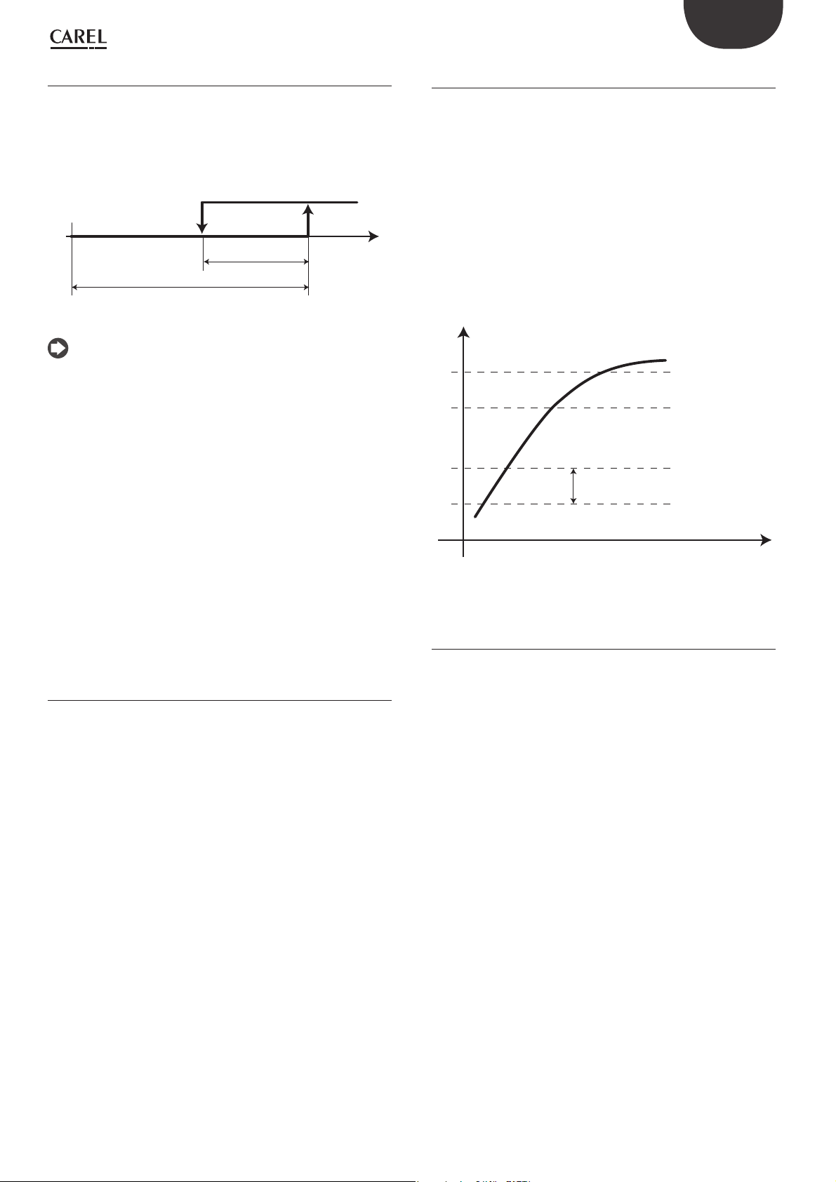
ENG
Pressure alarms from probe
The parameters corresponding to these alarms can be set in branch C.a.e
of the main menu for suction pressure, and D.a.e for condensing pressure.
For these types of alarms, reset is automatic and the activation threshold
and diff erential can be set, as well as the type of threshold, which may be
absolute or relative to the control set point. The fi gure shows an example
of setting the threshold to relative.
HP
Dierential
Relative threshold
AlarmSetpoint
Fig. 8.c
Note: for temperature control, the alarms from probe are managed
based on temperature even when pressure probes are fi tted.
The eff ects of the diff erent pressure alarms from probe are described
below.
Low suction pressure from probe
The low suction pressure alarm from probe has the eff ect of stopping all
the compressors without observing the times.
High suction pressure from probe
The high suction pressure alarm from probe has the eff ect of forcing
all the compressors on, ignoring the control times, but observing the
compressor protection times.
Pressure
8.5 High pressure prevention
Hecu CO2 can manage the high discharge pressure prevention actions,
involving:
• overriding the compressors and fans
Prevent by overriding the compressor and fans
The parameters corresponding to this function can be set in branch
G.c.a/G.c.b of the main menu.
The eff ect of this type of prevention action is to force on all the fans at
maximum speed and the BLDC compressor on at minimum speed.
An activation threshold can be set, which is always absolute, as well as the
deactivation diff erential.
Furthermore, the evaluation time and number of activations allowed in a
defi ned time period can also be set. If the number of activations is higher
than set, reset becomes manual.
Pressure
HP by pressostat
HP by probe
Prevent
dierential
Low condensing pressure from probe
The low condensing pressure alarm from probe has the eff ect of stopping
all the fans without observing the times.
High condensing pressure from probe
The high condensing pressure alarm from probe has the eff ect of forcing
all the fans on and stopping all the compressors, ignoring the times.
8.4 Anti liquid return MPX valve alarm
For alarms that stop the compressor, if the “anti liquid return MPX valve”
function is enabled, the evaporator valves will be forced closed. This
function can be enabled on screen Cag65.
In the event of a low pressure switch alarm, the valves will not be forced
closed, so as to allow the system to restart.
Below is the list of alarms that stop the compressor and close the valve:
• High pressure
• HP prevent lock (5 attempts)
• Low SH
• High receiver pressure
• SSH-DSH
• High or low oil level
• Leak alarm
• CO2 alarm
time
Fig. 8.d
8.6 MPXPRO/UltraCella alarms
The MPXPRO and/or UltraCella alarms are sent remote to the Hecu
CO2 user interface, which also forwards them to the supervisor for
management/logging.
49
Hecu CO2 +0300085EN rel. 2.2 - 07.05.2019

ENG
8.7 Alarm table
Screen
index
ALU02 Control probe absent At least one of the main probes is not confi gured
ALA01 Discharge temperature probe broken
ALA02 Gas cooler pressure probe broken
ALA03 Outside temperature probe broken
ALA04 Generic probe A on board 1 broken
ALA05 Generic probe B on board 1 broken
ALA06 Generic probe C on board 1 broken
ALA07 Generic probe D on board 1 broken
ALA08 Generic probe E on board 1 broken
Display Description Serious
correctly: P_suc, P_GC, T_out_GC, P_ric
or disconnected
or disconnected
or disconnected
or disconnected
or disconnected
or disconnected
or disconnected
or disconnected
Compressor discharge temperature probe
faulty or not confi gured correctly
Gas cooler pressure probe faulty
or not confi gured correctly
Outside gas cooler temperature probe faulty
or not confi gured correctly
Generic probe A faulty
or not confi gured correctly
Generic probe B faulty
or not confi gured correctly
Generic probe C faulty
or not confi gured correctly
Generic probe D faulty
or not confi gured correctly
Generic probe E faulty
or not confi gured correctly
alarm
Alarm Delay Reset
x Not present Auto
x Not present Auto
x Not present Auto
x Not present Auto
x Not present Auto
x Not present Auto
x Not present Auto
x Not present Auto
x Not present Auto
ALA24 Suction pressure probe broken
or disconnected
ALA25 Suction temperature probe broken
or disconnected
ALA43 Gas cooler out temp.probe broken Gas cooler outlet temperature probe faulty
ALA44 Receiver pressure probe broken
or disconnected
ALA46 Vapour injection pressure probe
broken or disconnected
ALA47 Vapour injection temperature probe
broken or disconnected
ALA55 Parallel line suction pressure probe
broken or disconnected
ALA 56 Parallel line suction temperature
probe broken or disconnected
ALA57 LT line discharge pressure probe
broken or disconnected
ALA58 Parallel line discharge temperature
probe broken or disconnected
ALB01 Common low pressure switch alarm Low pressure switch on the suction line trips below the
ALB02 Common high condensing pressure
switch alarm
ALB03 Low condensing pressure alarm P_GC falls below a threshold set on De07 x De03 Auto
ALB04 High condensing pressure alarm P_GC exceeds a threshold set on De06 x De01 Auto
Compressor suction pressure probe faulty or not
confi gured correctly
Compressor suction temperature probe faulty or not
confi gured correctly
or not confi gured correctly
Receiver pressure probe faulty
or not confi gured correctly
Vapour injection pressure probe faulty
or not confi gured correctly (LT only)
Vapour injection temperature probe faulty
or not confi gured correctly (LT only)
Parallel compressor suction pressure probe faulty or not
confi gured correctly
Parallel compressor suction temperature probe faulty or
not confi gured correctly
LT compressor discharge pressure probe
faulty or not confi gured correctly
Parallel compressor discharge temperature
probe faulty or not confi gured correctly
threshold (number of automatic resets /
in min.)
High pressure switch on the condensing line trips
above the threshold
x Not present Auto
x Not present Auto
x Not present Auto
x Not present Auto
x Not present Auto
x Not present Auto
x Not present Auto
x Not present Auto
x Not present Auto
x Not present Auto
x Hc02 Hc03
x Hc01 Auto/manual
ALB05 Liquid level alarm Low liquid level alarm from DI with consequent low
ALB06 Common oil diff erential alarm Low oil level in receiver alarm
ALB07 Fan common overload Fan overload alarm from DI x De05 Auto/manual
Hecu CO2 +0300085EN rel. 2.2 - 07.05.2019
pressure inside the receiver
from DI
Open solenoid valve installed between oil
separator and receiver to increase oil level
50
x Hc04 Auto
x Hc04 Auto

Action Troubleshooting
Unit switched off Check control probes *
ENG
No control action
Corresponding functions disabled:
- T_dis control by Hb02
- speed control based onT_dis by Hb03
No control action
The HPV valve is set to a safety percentage on Fhb13
Corresponding functions disabled:
- control switches to T_out in case of P_GC fault on
Dg14
- gas cooler speed up on T_out on Dg13
Corresponding functions disabled
- if probe A is faulty or not correctly confi gured, the
generic function associated with it will no longer
be active
Corresponding functions disabled
- if probe B is faulty or not correctly confi gured, the
generic function associated with it will no longer
be active
Corresponding functions disabled
- if probe C is faulty or not correctly confi gured, the
generic function associated with it will no longer
be active
Corresponding functions disabled
- if probe D is faulty or not correctly confi gured, the
generic function associated with it will no longer
be active
Corresponding functions disabled
- if probe E is faulty or not correctly confi gured, the
generic function associated with it will no longer
be active
A fi xed percentage of speed can be set in the event
of faulty or disconnected probe on Cag03
No control action Check T_suc probe *
Check T_dis probe *
Check P_GC probe *
Check T_out *
Check generic an.input A *
Check generic an.input B *
Check generic an.input C *
Check generic an.input D *
Check generic an.input E *
Check P_suc probe *
Fan shutdown Check T_out_GC probe *
No control action
The RPRV valve is set to a safety percentage on
Fhb26
No control action
Vapour injection disabled
No control action
Vapour injection disabled
No action on the parallel compressor
Parallel compressor stops for control
No action on the parallel compressor Check T_suc_par probe *
Parallel compressor shutdown Check P_dis_LT probe *
No action on the parallel compressor Check T_dis_LT probe *
Compressor shutdown • Check operation, type and setting of evaporator expansion valves (e.g. valve stuck closed)
Compressor shutdown • Check operation, type and setting of evaporator expansion valves (e.g. valve stuck open)
Fans forced to 0% while the alarm is active • Check fans and corresponding alarm settings
Fans forced to 100% while the alarm is active • Check fans and corresponding alarm settings
/ • Check refrigerant charge in the circuit, recharge is necessary
/ • Check oil level in the circuit
Check P_ric probe *
Check P_vap_inj probe *
Check T_vap_inj probe *
Check P_suc_par probe *
• Check mechanical pressure switch safety thresholds
• Check mechanical pressure switch safety thresholds
• Check HPV valve setting and operation
• Check correct mechanical operation of the fans (wiring, confi guration,..)
• Check correct positioning and operation of P_GC probe (compare reading on display against pressure gauge reading)
• Check correct compressor operation (possible presence of liquid, excessive refrigerant charge, compressor sizing, ...)
• Check correct mechanical operation of the fans (wiring, confi guration,..)
• Check correct positioning and operation of P_GC probe (compare reading on display against pressure gauge reading)
• Check correct compressor operation (low refrigerant charge, compressor sizing,..)
• Check HPV valve setting and operation
• Check pressure in the receiver
• Check operation of solenoid valve between separator and oil receiver
• Possible oil trapped in the evaporators
/ • Check fan settings and confi guration
• Check fan sizing in relation to the application
• Check correct mechanical operation of the fans (wiring, confi guration,..)
• Check HPV valve setting and operation
51
Hecu CO2 +0300085EN rel. 2.2 - 07.05.2019

ENG
Screen
index
ALB15 High suction pressure Suction pressure exceeds a threshold set on Cae24 x Cae25 Auto
ALB16 Low suction pressure Suction pressure below a settable threshold x Cae27 Auto
ALB22 Oil sensor level broken
ALC01 Alarm 1 compressor 1 Alarm from DI for BLDC compressor set on Cae02 (ge-
ALC02 Alarm 2 compressor 1 Alarm from DI for BLDC compressor set on Cae05 (ge-
ALC26 Alarm 1 parallel compressor Alarm from DI for parallel compressor set on Cbe02
ALC27 Alarm 2 parallel compressor Alarm from DI for parallel compressor set on Cbe05
ALC51 CO2 level alarm Refrigerant leakage outside of the circuit
ALC51 Leak detector alarm Refrigerant leakage in the circuit signalled by DI x Hc05 Auto
ALF01 Fan overload Alarm from DI for one or two fans when fan common
ALG01 Al_Clock Alarm due to problem reading controller clock x
ALG02 Extended memory error Faulty controller alarm x
ALG11 High thermostat 1…5 alarms High temperature (pressure) alarm
ALG15 Low thermostat 1…5 alarms Low temperature (pressure) alarm
ALG19 High modulating 1-2 alarms High temperature (pressure) alarm
ALG23 Low modulating 1-2 alarms Low temperature (pressure) alarm
ALG27 Generic 1-2 normal alarms Generic alarm 1 or 2 x Ffc07, Ffc09 Auto
ALG28 Generic 1-2 serious alarms Serious generic alarm 1 or 2 x Ffc07, Ffc09 Auto
ALT01 Compressor working hours Operating hours exceeded for the compressor(s)
ALT07 HPV valve alarm HPV valve alarm from DI settable on Fha04 and HPV
ALT08 RPRV valve alarm RPRV valve alarm from DI settable on Fha05
ALT15 Low superheat alarm Low SH alarm settable on Cae30 x Cae30 Auto/manual
Display Description Serious
or disconnected
Oil level sensor faulty or not confi gured
correctly (LT only)
The alarm is activated when neither of the two
sensors is active from DI
neric, overload, high pressure, low pressure, oil)
neric, overload, high pressure, low pressure, oil)
(generic, overload, high pressure, low pressure, oil)
(generic, overload, high pressure, low pressure, oil)
signalled by DI
overload is disabled on De05
for generic function 1 to 5
for generic function 1 to 5
for generic modulating function 1 or 2
for generic modulating function 1 or 2
selected on Cac13
Compressor operating time shown in Cac01
brought to safety position (Fhb10)
and RPRV brought to safety position (Fhb23)
alarm
x 10 s Auto
x Cbe04 Auto/manual
x Cbe07 Auto/manual
Alarm Delay Reset
x Cae04 Auto/manual
x Cae07 Auto/manual
x Hc06 Auto
x De05 Auto/manual
x Ffa09-13-17-
21-25
x Ffa09-13-17-
21-25
x Ffb08-Ffb14 Auto
x Ffb09-Ffb15 Auto
x Not present Manual
x Not present Auto
x Not present Auto
Auto
Auto
ALT19 DSH Low liquid fl owback SH less than 0 K and DSH at discharge less
ALT20 HPV Valve position warning The HPV valve is at an opening percentage higher than
ALT21 RPRV Valve position warning The RPRV valve is at an opening percentage higher
ALT17 HPV set point warning
Gas cooler press. too low/high,
deviation from current set point
ALT18 High receiver pressure alarm Receiver pressure higher than a settable threshold
ALW10 Low superheat warning The SH value as shown on Aa01 is less than a
ALW24 Power plus device offl ine BLDC compressor inverter not present
ALW25 Power+ inverter alarm Inverter alarm n.xx; ALW25 indicates the type of alarm
ALW26 Compressor start failure The diff erential between compressor discharge and
than 10 K for a time set on Cae41
a certain threshold settable on Fhb27
than a certain threshold settable on Fhb28
P_GC is higher or lower than a diff erential set on Fhb17
in relation to the current set point
(Fhb25)
threshold set on Cae30
Warning before the alarm is activated, with a delay that
can be set on Cae30
or not connected
generated by the inverter
suction pressure does not increase by a certain value
in a set period of time. Minimum variation in pressure
diff erence and time period can be set on Cag50
x Cae41 Auto/manual
x Fhb27 Auto
x Fhb28 Auto
x Fhb17 Auto
x Fhb25 Auto
x Not present Auto
x 30-90s Auto
x Not present Auto
x Cag50 Auto for 0-9
attempts
Hecu CO2 +0300085EN rel. 2.2 - 07.05.2019
52

Action Troubleshooting
ENG
/ • Check correct compressor operation (presence of liquid, excessive refrigerant charge, compressor sizing,..)
Compressor shutdown, set on Cae27 • Check correct compressor operation (incorrect sizing, low refrigerant charge,..)
LT compressor and parallel compressor shutdown • Check the two level sensors (low, high)
Compressor shutdown • Check BLDC compressor operation based on the type of alarm
Compressor shutdown • Check BLDC compressor operation based on the type of alarm
Parallel compressor shutdown • Check parallel compressor operation based on the type of alarm
Parallel compressor shutdown • Check parallel compressor operation based on the type of alarm
Compressor shutdown, settable
on Hc06
Compressor shutdown and fan on
settable on Hc05
One or both fans shut down, depending on the
confi guration
Actions involving the clock no longer confi gured
Unit shutdown Change board
/ Check the set probe *
/ Check the set probe *
/ Check the set probe *
/ Check the set probe *
/ Check the set probe *
/ Check the set probe *
/ • Check operating hour threshold on screen Cac13
• Evaporators with valves fully open at the same time (e.g. MOP set incorrectly on MPXPRO, valves stuck open,..)
• Evaporators with valves closed and compressors running (valves stuck closed,..)
• Check wiring and electrical panel connections
• Check DI confi guration
• Type of alarm signalled settable on screen Cae02
• Type of alarm signalled settable on screen Cae05
• Type of alarm signalled settable on screen Cbe02
• Type of alarm signalled settable on screen Cbe05
• Check circuit piping
• Check refrigerant charge level in the circuit
• Check piping, valves and circuit components
• Check correct compressor operation
• Check fan connections and correct fan operation
• Fan sizing not suitable for the system
• Excessive refrigerant charge in the circuit
• Reset operating hours on screen Cac14
HPV brought to set safety position
when alarm from DI activated
RPRV brought to set safety position
when alarm from DI activated
Compressor shutdown, set on Cae30 • Check the correct reading of the probes set for SH (P_suct and T_suct)
Compressor shutdown • Check correct compressor operation (presence of liquid, refrigerant charge, sizing,..)
/ • Check status of P_GC and T_out_GC probes (type, wiring, correct positioning,..)
/ • Check status of P_ric probe (type, wiring, correct positioning,..)
/ • Check status of T_out_GC probe (type, wiring, correct positioning,..)
Compressor shutdown, set on Cae42 • Check RPRV valve setting, operation and installation (mechanical operation, sizing in relation to the application,
Low superheat warning signal
No control action
Compressor shutdown • Check inverter power supply
Compressor shutdown • Check inverter operation and status
Compressor shutdown with manual reset
after n restart attempts
• Check the device connected to the DI
• Check the device connected to the DI
• Check compressor status (frost on the outside)
• Check liquid return from evaporators (SH reading on MPXPRO and UC)
• Check evaporator valve operation and status (valves blocked, incorrect confi guration, wiring,..)
• Check MPXPRO/UC setting (probe operation and positioning, correct parameter confi guration, compare probe
reading against pressure gauge reading)
• Check correct mechanical operation of the fans (wiring, confi guration, sizing in relation to the application,..)
• Check HPV valve setting, operation and installation (mechanical operation, sizing in relation to the application,
correct opening/closing)
• Check warning threshold setting
• Check RPRV valve setting, operation and installation (mechanical operation, sizing in relation to the application,
correct opening/closing)
• Check warning threshold setting
• Check mechanical operation of the fans (wiring, confi guration, sizing in relation to the application,..)
• Check warning threshold setting
correct opening/closing)
• Check synchronisation with external driver (wiring and connections, confi gurations,..)
• Sizing of the receiver in relation to the application
• Charge in the circuit
• Check the correct reading of the probes set for SH (P_suct and T_suct)
• Check compressor status (frost on the outside)
• Check liquid return from evaporators (SH reading on MPXPRO and UC)
• Check phase connection between compressor and inverter (wiring and connections)
• Check STO
• Check confi guration of inverter parameters (baud rate, parity, number of bits)
• Check list of alarms in the inverter manual (explanation of the alarms that may occur on the inverter)
• Check compressor connections to the inverter (swapped phases, wiring and incorrect connections,..)
• Check correct compressor operation (liquid in the compressor, excessive charge in the circuit,..)
• Check evaporator valve status (valves stuck open)
• Check positioning, installation and correct operation of P_GC probe (positioning before the check valve at the compressor discharge, checking the values are read correctly)
• Check positioning, installation and correct operation of P_suct probe
53
Hecu CO2 +0300085EN rel. 2.2 - 07.05.2019

ENG
Screen
index
ALW27 Envelope alarm Compressor operation outside of the envelope x Cag55 Auto
ALW28 High discharge gas temperature Compressor discharge temperature exceeds a
ALW29 Compressor low pressure diff erential
ALW30 Inverter model not compatible
ALW37 Alarm stores (generic) Generic alarm evaporator 1 to 5
ALW40-53-6679-92
ALW41-54-6780-93
ALW42-55-6881-94
ALW43-56-6982-95
ALW44-57-7083-96
ALW45-58-7184-97
ALW46-59-7285-98
Display Description Serious
threshold set on Hb02
(insuffi cient lubrication)
(Power+ only)
Store 1…5 offl ine Evaporator 1 to 5 confi gured by Hecu but MPXPRO/UC
Store 1…5: Low temperature alarm Low temperature alarm for the probe set on
Store 1…5: High temperature alarm High temperature alarm for the probe set on
Store 1…5: Low temperature alarm 2 Low temperature alarm for the probe set only on MPX-
Store 1…5: High temperature alarm 2 High temperature alarm for the probe set only on
Store 1…5: Defrost timeout End defrost procedure by timeout signal, evaporator
Store 1…5: Low superheat alarm SH evap. 1 to 5 below the threshold; control is activated
Diff erence between BLDC compressor
suction and discharge pressure too low
Selected inverter model not compatible with the type
of compressor set on Cag02
ALW37 shows the evaporators with active alarms
device not connected via Fieldbus or offl ine
MPXPRO/UC evaporator 1 to 5
MPXPRO/UC evaporator 1 to 5
PRO evaporator 1 to 5
MPXPRO evaporator 1 to 5
1 to 5
to rapidly close the valve and prevent liquid from
returning to the compressor
alarm
x Not present Auto
Alarm Delay Reset
x Cag55 Auto
x Not present Auto
x Not present Auto
x Not present
x from MPXPRO/
UC (Ad)
x from MPXPRO/
UC (Ad)
x from MPXPRO
(Ad2)
x from MPXPRO
(Ad2)
x from MPXPRO/
UC (dP1, dP2)
x from MPXPRO
(P9)
Auto
Auto
Auto
Auto
Auto
Auto
ALW47-60-7386-99
ALW48-61-7487-ALZ00
ALW49-62-7588-ALZ01
ALW50-63-7689-ALZ02
ALW51-64-7790-ALZ03
ALW52-65-7891-ALZ04
ALZ06 Liquid return from MPX 1…5
ALZ07 Warning: no DO confi gured for
ALZ08 Carel EXV valve not confi gured on
ALP01 Power + n.2 (n.3) offl ine Parallel compressor inverter not present
ALP02 Power+ n2 (n.3) alarm Inverter no. 2 (no. 3) alarm n.xx
Store 1…5:
Low suction temperature alarm
Store 1…5: MOP alarm Evap. pressure in cabinet 1 to 5 above the threshold
Store 1…5: LOP alarm Evap. pressure in cabinet 1 to 5 below the
Store 1…5:
stepper driver communication error
Store 1…5: stepper motor error Electronic valve not properly installed x
Store 1…5: installation or confi g
problems on EEV driver
offl ine during fl ush
vapour injection fl ow in BLDC
MPXPRO
The unit will switch off in 10 hours
Suction temperature (t_gs) 1 to 5 below threshold, with
the risk of liquid returning to the compressor
(parameter PM1 on MPXPRO); control is activated
(parameter PM2) to rapidly close the valve
threshold (parameter PL1 on MPXPRO); control is activated (parameter pL2) to rapidly open the valve
Incorrect setting of parameter P1 on MPXPRO 1 to 5,
which must be set to 2 (management of Carel E2V
electronic valve is required)
Valve 1 to 5 end of travel alarm.
Valve blocked alarm ("Blo") signalled on MPXPRO
MPX 1 to 5 offl ine alarm during washing x
No DO confi gured for the vapour injection function
for BLDC compressor in LT applications or for parallel
compressor, set on Fda07
Valve managed by MPXPRO/UC is not a Carel E2V
electronic valve.
or not connected
Alarm screen ALW25 indicates the type of alarm generated by the inverter
x from MPXPRO
(P12)
x from MPXPRO
(PM3)
x from MPXPRO
(PL3)
x from MPXPRO
(P1)
x
x Not present Auto
x
x 30-90s Auto
x Not present Auto
Auto
Auto
Auto
ALP03 Parallel compressor start failure The diff erential between discharge (P_GC)
Hecu CO2 +0300085EN rel. 2.2 - 07.05.2019
and suction pressure for the parallel compressor
(P_ric) does not increase by a certain value in a
period of time set on Cbg50
54
x Cbg50 Auto for 0 to 9
attempts

Action Troubleshooting
ENG
Compressor shutdown, with a
reduction in speed set on Cag54
Compressor shutdown • Check installation and correct operation of the temperature probe (wiring, electrical connections and comparison
Compressor shutdown • Check correct compressor operation (charge, sizing, presence of liquid,..)
Compressor does not start • Check the inverter model installed against the model required by the compressor in the system on screen Cag02
/ • Check evaporator confi guration on screen Eab00 and then on Hecu (number of evaporators, sizing, type of controller
/ • Check evaporator confi guration on screen Eab00 and then on Hecu (number of evaporators, sizing, type of controller
Signal-only alarm
- No action
Signal-only alarm
- No action
Signal-only alarm
- No action
Signal-only alarm
- No action
Signal-only alarm
- No action
Signal-only alarm
- No action
Signal-only alarm
- No action
Signal-only alarm
- No action
Signal-only alarm
- No action
Signal-only alarm
- No action
• Check positioning, installation and correct operation of P_GC probe (positioning before the check valve at the compressor discharge, checking the values are read correctly)
• Check positioning, installation and correct operation of P_suct probe; 8 operating zones outside of envelope
• Check correct compressor operation (charge, sizing, presence of liquid,..)
against pressure gauge reading)
• Check compressor (enabling the liquid injection function if the discharge temperature is too high, connections to
the inverter)
• Check charge in the circuit (low charge)
• Check positioning, installation and correct operation of P_GC probe (positioning before the check valve at the compressor discharge, checking the values are read correctly)
• Check positioning, installation and correct operation of P_suct probe
• Metallic noise made by compressor due to lack of lubrication by the oil
installed,..)
• Check Fbus connection (connections, wiring, polarity,..)
• Check MPXPRO/UC status (check confi guration on the controller, serial address parameter H0; if necessary, repeat
commissioning procedure)
installed,..)
• Check Fbus connection (connections, wiring, polarity,..)
• Check MPXPRO/UC status (check confi guration on the controller, serial address parameter H0; if necessary, repeat
commissioning procedure)
• Check cabinet/showcase status (correct fan operation, set point)
• Check MPXPRO/UC setting (confi guration and setting of control probes)
• Check cabinet/showcase status (correct fan operation, set point)
• Check MPXPRO/UC setting (confi guration and setting of control probes)
• Check cabinet/showcase status (correct fan operation, set point)
• Check MPXPRO setting (confi guration and setting of control probes)
• Check cabinet/showcase status (correct fan operation, set point)
• Check MPXPRO setting (confi guration and setting of control probes)
• Check cabinet/showcase status (correct fan operation, set point)
• Check MPXPRO setting (confi guration and setting of control probes)
• Check t_gs and p_ev probes (type, wiring, installation position, probe limits, reading compared against mechanical
device)
• Check alarm settings
• Check E2V valve operation (correct opening/closing, check that it is not stuck open)
• Compare the SH value read by Hecu to check correct probe operation
• Check t_gs probe (type, wiring, installation position, probe limits, reading compared against mechanical device)
• Check alarm settings
• Check E2V valve operation (correct opening/closing, check that it is not stuck open)
• Check cabinet/showcase status (correct fan operation, set point)
• Check MOP settings (PM parameters on MPXPRO)
• Check compressor capacity in relation to total system cooling demand (insuffi cient compressor capacity)
• Check useful when commissioning the system
• Check cabinet/showcase status (correct fan operation, set point)
• Check compressor capacity in relation to total system cooling demand (insuffi cient compressor capacity)
• Check LOP settings (PL parameters on MPXPRO)
• Check parameter P1 (this must be set to 2) on MPXPRO in relation to the valve installed on the evaporator (this must
be the Carel E2V electronic valve)
Signal-only alarm
- No action
Signal-only alarm
- No action
Compressor shutdown • Check Fbus connection (connections, wiring, polarity,..)
Signal-only alarm
- No action
Unit shutdown in 10 hours Check parameter P1 (this must be set to 2) on MPXPRO in relation to the valve installed on the evaporator (this must
Parallel compressor shutdown • Check inverter power supply
Parallel compressor shutdown • Check positioning, installation and correct operation of P_GC probe (positioning before the check valve at the com-
Parallel compressor shutdown with manual reset
after n restart attempts
Check electronic valves on the respective cabinets
Check parameter P14 on MPXPRO
• Check MPXPRO/UC status (check confi guration on the controller, serial address parameter H0; if necessary, repeat
commissioning procedure)
• Check DO setting for LT compressor on screen Fda07
• Check DO setting for parallel compressor on screen Fda08
be the Carel E2V electronic valve)
• Check phase connection between compressor and inverter (wiring and connections)
• Check STO
• Check confi guration of inverter parameters (baud rate, parity, number of bits)
pressor discharge, checking the values are read correctly)
• Check positioning, installation and correct operation of P_ric probe; 8 operating zones outside of envelope
• Check correct compressor operation (charge, sizing, presence of liquid,..)
• Check compressor connections to the inverter (swapped phases, wiring and incorrect connections,..)
• Check correct compressor operation (liquid in the compressor, excessive charge in the circuit,..)
• Check positioning, installation and correct operation of P_GC probe (positioning before the check valve at the compressor discharge, checking the values are read correctly)
• Check positioning, installation and correct operation of P_ric probe
55
Hecu CO2 +0300085EN rel. 2.2 - 07.05.2019

ENG
Screen
index
ALP04 Parallel compressor envelope alarm Compressor operation outside of the envelope x Cbg55 Auto
ALP05 Parallel compressor high discharge
ALP06 Parallel compressor low pressure
ALP07 Parallel compressor inverter model
(*) probe type, wiring, probe installation position, probe limit settings, comparison
of value displayed against physical instrument (pressure gauge,..)
Display Description Serious
gas temperature
diff erential (insuffi cient lubrication)
not compatible (power+ only)
The parallel compressor discharge temperature exceeds
a certain threshold set on Hb04
Diff erence between parallel compressor
suction and discharge pressure too low
Selected inverter model for parallel compressor not
compatible with the type of compressor used
alarm
Alarm Delay Reset
x Not settable Auto
x Cbg55 Auto
x
Hecu CO2 +0300085EN rel. 2.2 - 07.05.2019
56

Action Troubleshooting
ENG
Compressor shutdown, with speed reduction set on
Cbg54
Parallel compressor shutdown • Check t_dis_par probe (type, wiring, installation position, probe limits, reading compared against mechanical device)
Parallel compressor shutdown • Check correct compressor operation (charge, sizing, presence of liquid,..)
Parallel compressor does not start Check the inverter model installed against the model required by the compressor in the system on screen Cbg02
• Check positioning, installation and correct operation of P_GC probe (positioning before the check valve at the compressor discharge, checking the values are read correctly)
• Check positioning, installation and correct operation of P_ric probe; 8 operating zones outside of envelope
• Check correct compressor operation (charge, sizing, presence of liquid,..)
• Check alarm threshold setting on screen Hb04
• Check positioning, installation and correct operation of P_GC probe (positioning before the check valve at the compressor discharge, checking the values are read correctly)
• Check positioning, installation and correct operation of P_ric probe
• Metallic noise made by compressor due to lack of lubrication by the oil
Tab. 8.c
57
Hecu CO2 +0300085EN rel. 2.2 - 07.05.2019

ENG
9. SOFTWARE UPDATE
9.1 Uploading/updating the software
The following methods can be used to update the fi rmware and acquire
the log fi les on pCO controllers:
• SmartKey programming key;
• pCO manager tool, a program installed on a PC.
Smart key
The PCOS00AKY0 key is an electronic device used to program and service
the pCO sistema family controllers. PCOS00AKY0 simplifi es data transfer
between the controllers installed and a personal computer by exploiting
the high capacity fl ash memory for storing software applications, BIOS
and variable logs. The pCO is connected directly via the telephone
connector using the cable supplied, while to transfer the data to a
personal computer, the USB adapter code PCOS00AKC0 is required.
The power supply comes either via the USB port on the PC or from the
controller, therefore no external power supply is needed.
USB
telephone cable
start
mode
PCOS00AKC0
For the operating instructions, see par. 9.1.
Operating instructions
start
mode
Programming the Smart Key via Personal Computer
The operating modes described in the table below can be confi gured
using a program on a PC. The program can also load the software to the
key or transfer logged data from the controller to the hard drive.
Type Function Mode button
B Update software from key to pCO (BIOS,
application program, parameters,...)
C* Copy software from pCO to pCO (BIOS,
application program, parameters,...)
D Read logs Disabled
E Read logged data and software from pCO
(BIOS, application program, parameters,...)
F Read logs Disabled
G Copy from pCO to pCO and read logs Switches the key to write
*: Default mode
USB
Fig. 9.a
start
mode
Fig. 9.b
Disabled
Switches the key from write
mode to read mode
Disabled
mode, read mode and read
logs mode
Tab. 9.a
The key is factory-programmed in read/write mode (type C) so that it can
be used immediately to transfer software from one controller to another.
When the key is connected to the personal computer, the symbols have
the following meanings:
Flashing Waiting for connection to PC
Alternating
When connected to PC indicates
data transfer in progress
The programming key is compatible starting from BIOS version 3.43 and
BOOT version 3.01. For more detailed information on programming the
key, see to the pCO Manager manual.
Using the Smart Key with the pCO/μPC programmable controllers
Switch off the pCO, remove any peripherals connected in the pLAN
and plug the key into the telephone connector on the controller. When
switching on again, all the symbols light up momentarily and the buzzer
emits a beep. A few seconds later the key becomes operational. This
waiting period is indicated by the fl ashing of
. The controller then
enters programming mode and the start button is on steady; press the
button to start data transfer
Important:
• if the key is type B, C or G (in write mode) pressing the start button will
immediately delete the software already loaded on the pCO.
• Do not remove the key while data is being transferred to the key itself,
as the fi le being transferred will be lost and the corresponding space
will not be restored. To restore the original capacity all the fi les will
need to be deleted. If the key is type “C” or “G”, simply perform a new
application read operation.
Meanings of buttons/symbols
Flashing: the key is connecting to the pCO; during this phase, which
may last a few seconds, the start button is disabled
start
start+
start+
start+
mode
If the key is type C or G, pressing mode for 1 s switches from read mode
to read logs (G only) or write mode; the symbols (write to pCO),
(read from pCO),
type C or G, the mode key is disabled and the light is off . The start button
starts the read or write operation, which will be indicated by the fl ashing
of the corresponding symbol (
to progress. When the operation is completed, the buzzer will sound
intermittently for 2 seconds. Pressing the start button again will make the
buzzer sound without repeating the operation; to repeat the operation,
the key must fi rst be unplugged. In the event of an error, the symbol
comes on in combination with the other LEDs. The following table can
be used to fi nd the cause of the problem.
Flashing: the key has detected the pCO and is checking the access
rights
On steady: pressing the start button will start writing the software to
the pCO
On steady: pressing the start button will start reading the software
from the pCO
On steady: pressing the start button will start reading the logs from
the pCO
On steady: for type C or G keys, pressed for 1 second switches from
read to write mode
(read logs) refl ect the selected mode. If the key is not
or ), at a frequency proportional
Tab. 9.b
Hecu CO2 +0300085EN rel. 2.2 - 07.05.2019
58

ENG
C
VSTD
UTLF
0
Errors before pressing the START button
Communication error: no response
from the pCO or: Key fi rmware version
incompatible
fi les (memory empty; no kit for the type of
pCO connected)
Incompatibility between the software on
the key and the pCO HW
Incompatibility between application program and pCO HW (program size)
+ +
+mode
+mode
+
+ +start
+ +mode
+ +
fl ashing
on steady Password error
fl ashing Incompatible key type
on steady The key is missing one or more required
on steady + start
fl ashing
on steady +
mode
fl ashing
on steady No logged data on the pCO
on steady Key type not programmed
Errors after pressing the START key
fl ashing and
+start+ +buzzer
+start+ +buzzer
+start+ +buzzer
+ +
+
buzzer on pulsing
fl ashing and
buzzer on pulsing
fl ashing and
buzzer on pulsing
on steady +
fl ashing
on steady
fl ashing Generic error
Tab. 9.c
The write command failed
The read command failed
The read logs command failed
Incompatibility between log
confi guration and pCO HW
(no dedicated fl ash memory).
This error does not aff ect the
writing of the other fi les
Insuffi cient space to read
logged data
Tab. 9.d
As regards the port number, follow the instructions shown in the Wizard
for automatic identifi cation (e.g. COM4).
Fig. 9.d
Power the controller off and on again, and run the connect command to
make the connection; when connected, the ONLINE icon will be shown
fl ashing in the bottom left corner.
Fig. 9.e
Application program installation
•
Select the directory where the application program fi les are located,
and run the Upload command to load this onto the pCO controller.
pCOmanager: operating instructions
pCO Manager is a program for managing all confi guration, debugging
and maintenance operations on CAREL pCO sistema devices. It can
be installed as a stand-alone program or integrated into the 1tool
programming environment.
Installing pCOmanager
Go to http://ksa.carel.com, and in the pCO sistema section select pCO_
manager. After accepting the general terms and conditions for the free
software license, a window will open for downloading the pCO_manager.
zip fi le. Install the program on the computer.
PC - pCO controller connection
The computer's USB port must be connected to a cable with USB/RS485
converter, and this must in turn be connected via telephone cable to the
pLAN port on the pCO.
USB
CVSTDUTLF0
power supply
USB
Fig. 9.f
Commissioning
•
Use the mouse to select commissioning at the bottom left.
A new work environment will be opened.
Fig. 9.g
• Run the "confi gure device" command to display all of the application
variables. These can be selected based on the categories shown at the
bottom.
Fig. 9.c
When the pCO_manager program is opened, a screen is displayed,
showing the connection settings at the top right. Select:
1. local connection;
2. baud rate: Auto;
3. device search: Auto (pLAN).
59
Fig. 9.h
Hecu CO2 +0300085EN rel. 2.2 - 07.05.2019

ENG
Changing a parameter
Choose the category of parameters and then the parameter to be set: this
is highlighted by a blue line (e.g. recovery.recovery_type).
Fig. 9.i
1. Double click the mouse on the read column. A window is displayed
for entering the new parameter value.
Fig. 9.j
2. Write the new value (e.g. 3) and select OK. The new value is displayed
in the written column. To write the parameter to the pCO controller,
click the right mouse button and run the write selected command.
The new value is displayed, confi rm the value in the written column.
Fig. 9.k
Finally, run the Save command to generate the project .2cw fi le.
Support les
At the end of the application program design phase, 1tool generates
several fi les during compilation; two of these are required for
commissioning:
• <applicationName>.2CF (variable descriptor);
• <applicationName>.2CD (descriptor of categories and access profi les).
In addition to these fi les, the <applicationName>.DEV fi le can also be
managed, which contains the pre-set unit parameters. After having
completed commissioning, either for confi guration or monitoring, the
user can generate the following fi les:
• <applicationName>.2CW (descriptor of categories, access profi les,
monitoring groups);
• <CommissioningLogFileName>.CSV (fi le used for the commissioning
log, with the data of the variables logged during monitoring).
The commissioning confi guration phase thus requires the following fi les:
.2CF, 2CD and where possible the .DEV fi le, which can be imported and
exported.
For the monitoring phase, in addition to the above fi les, the .2CW fi le
may be needed, with the defi nition of the specifi c work environment. The
commissioning log fi le is a simple output fi le.
pCO Load: basic concepts
pCOLoad is the module that manages:
• uploading to fl ash memory (ProgKeyX device or key installed on the
pCO);
• uploading to NAND memory on certain devices;
• downloading logs, .DEV fi le and P memory (from fl ash memory).
• downloading NAND memory fi les, if present.
The following fi les are exchanged with the pCO fl ash memory:
• Boot.BIN (download reserved, upload enabled from menu);
• Bios.BIN (download reserved);
• <applicationName>.BLB (download reserved );
• <applicationName>.BIN (download reserved );
• <applicationName>.DEV;
• <applicationName>.GRT (upload only, from which the .GRP is
extracted);
• <applicationName>.IUP;
• <applicationName>.LCT;
• <applicationName>.PVT;
• <pCOlogName>.BIN, <pCOlogName>.CSV, <pCOlogName_GRAPH>.
CSV (only if logs have been confi gured, download only).
The following fi les are exchanged with the pcO NAND memory:
• All of the fi les that the pCO can autonomously copy to the fl ash
memory (see the previous list);
• External fi les (e.g.: PDF, .doc for documentation).
Commissioning tool: basic concepts
Note: the following paragraphs are taken from the pCOmanager
program online help; refer to this for any further details.
The commissioning tool is real-time confi guration and monitoring
software used to check the operation of an application program installed
on a pCO, for commissioning a pCO, debugging and maintenance.
This tool can be used to set the confi guration parameters, modify the
values of volatile and permanent variables, save the trends of the main
unit values to a fi le, manually manage the unit I/Os using simulation fi les,
and monitor/reset the alarms on the unit where the device is installed.
The commissioning operations fi rst require confi guration of the work
environment, typically the task of the designer. The active 1tool project
is automatically loaded by the pCO Manager. The commissioning tool
confi guration functions allow the designer to decide which variables
will be included in the monitoring/log/trend/event monitoring activities,
to organise variables into categories, and to set groups of confi guration
parameter. Users who use the commissioning tool during maintenance
operations will already have access to the required variables, and will be
able to refer to pre-set confi guration values.
Hecu CO2 +0300085EN rel. 2.2 - 07.05.2019
LogEditor: basic concepts
LogEditor is the module used to confi gure pCO device logs (pCO log).
Confi guring pCO logs involves defi ning a number of sets of variables for
specifying which variables should be logged, the logging method (by
frequency or by event) and the guaranteed minimum number of records
required. Confi guration is based on a binary fi le (.PVT – Public Variable
Table), which is generated by 1Tool and contains the descriptive data of
the variables that can be logged. All the log confi gurations so defi ned
are saved in the .LCT (Log Confi guration Table) binary fi le, which must be
uploaded to the pCO together with the .PVT fi le. Log confi guration data is
also saved in a fi le that can be used only by LogEditor – the .LEF fi le, which
must be saved to be edited with LogEditor when necessary. LogEditor
can be used even when the device is not connected.
Once the fi les for logging are uploaded to the pCO, the pCO saves the
logged data in the following fi les:
• a .BIN fi le containing all the data in binary format;
• a .CSV fi le containing the same data but in a generic format with
comma separated values;
• a *_GRAPH.CSV fi le with the same data, to be used for graphs.
60

9.2 Software revision history
New version 3.0.012
ENG
61
Hecu CO2 +0300085EN rel. 2.2 - 07.05.2019

ENG
Notes:
Hecu CO2 +0300085EN rel. 2.2 - 07.05.2019
62


CAREL INDUSTRIES - Headquarters
Via dell’Industria, 11 - 35020 Brugine - Padova (Italy)
Tel. (+39) 049.9716611 - Fax (+39) 049.9716600
e-mail: carel@carel.com - www.carel.com
Agenzia / Agency:
+0300085EN rel. 2.2 - 07.05.2019
2
Hecu CO
 Loading...