


High Efficiency Solutions
heaterSteam - UR
NO POWER
& SIGNAL
CABLES
TOGETHER
READ CAREFULLY IN THE TEXT!
Electric resistance humidifi er
User manual


3
ENG
“heaterSteam” +0300080EN - rel. 1.0 - 27.04.2016
IMPORTANT WARNINGS:
This product is compliant with the European directives and other standards
specifi ed on the EC declaration of conformity. The customer is responsible
for suitably verifying any use of the product that implies application of
standards relating to any special environments and/or processes (e.g.
heavy industry, medical environments, maritime environments, railway
environments, etc.) other than those specifi ed by Carel.
The humidifi ers manufactured by CAREL are advanced products, whose
operation is specifi ed in the technical documentation supplied with the product
that can be downloaded, even prior to purchase, from the website www.carel.
com. Every product made by CAREL Industried, in relation to its advanced level of
technology, requires a qualifi cation/ confi guration / setup phse in order to best
fulfi l your specifi c application. The lack of such phase of study, as indicated in the
manual, can cause the fi nal product to malfunction, of which CAREL cannot be
held responsible. The client (builder, developer or installer of the fi nal equipment)
assumes all responsibility and risk relating to the confi guration of the product in
order to achieve the expected results in relation to the specifi c fi nal installation
and/or equipping. In this case, subject to specifi c agreements, CAREL acts as a
consultant for the success of the installation / start-up / use of the machine, but
in no case does it accept liability for proper operation of the humidifi er and of
the fi nal plant, should the warnings and recommendations in this manual or in
any other technical documentation of the product not be followed. In particular,
in addition to the obligation to observe the above mentioned warnings and
recommendations for proper use of the product, we recommend paying
attention to the following warnings:
DANGER ELECTRIC SHOCK: The humidifi er includes live electrical parts.
Disconnect the power supply before accessing internal parts, in case of
maintenance and during installation.
DANGER WATER LEAKS: The humidifi er automatically and constantly sucks
in/drains quantities of water. Malfunctions in the connections or humidifi er
may cause leaks.
DANGER OF BURNS: The humidifi er contains hot parts and delivers steam
at 100 °C / 212 °F.
• The product is designed exclusively to humidify rooms either directly or
through distribution systems (ducts).
• Installation, operation and maintenance must be performed by qualifi ed
personnel, aware of the necessary precautions and able to perform the
required operations correctly.
• All operations on the product must be carried out according to the
instructions given in this manual and on the labels applied to the
product. Any uses or modifi cations unauthorized by the manufacturer are
considered improper. CAREL denies all responsibility for such unauthorized
uses.
• Do not attempt to open the humidifi er in any way other than the ones
described in the manual.
• Follow the regulations in force in the place where the humidifi er is installed.
• Keep the humidifi er out of the reach of children and pets.
• Do not install and use the product near objects that can be damaged by
contact with water (or condensate). CAREL denies all responsibility for direct
or indirect damage as a result of loss of water from the humidifi er.
• Do not use corrosive chemicals, aggressive solvents or detergents to clean
the internal or external parts of the humidifi er, unless specifi cally indicated
in the user’s manual.
CAREL adopts a continuous development policy. Therefore, CAREL reserves the
right to carry out modifi cations and improvements to any product described
in this document without prior notice. The technical data in the manual
can undergo modifi cations without forewarning. The liability of CAREL in
relation to its own product is governed by CAREL general contract conditions
published on the website www.carel.com and/or by specifi c agreements with
clients; in particular, within the limits set by the applicable law, in no way will
CAREL, its employees or its branch offi ces/affi liates be responsible for any lack
of earnings or sales, loss of data and information, cost of replacement goods
or services, damage to objects or persons, work interruptions, or any direct,
indirect, accidental, patrimonial, coverage, punitive, special or consequential
damage in any way caused, be they contractual, out-of-contract, or due to
negligence or other responsibility originating from the installation, use or
inability of use of the product, even if CAREL or its branch offi ces/affi liates
have been warned of the possible damage.
ATTENTION
NO POWER
& SIGNAL
CABLES
TOGETHER
READ CAREFULLY IN THE TEXT!
Separate the probe cables and the digital input cables as much as possible
from the inductive load and power cables to prevent possible electromagnetic interference.
Never introduce power cables and signal cables (including those of electric
control board) into the same cable troughs.
The installation of the product must absolutely include the grounding
connection, using the special yellow-green terminal on the terminal block.
Do not use the neutral as grounding connection.
DISPOSAL
The humidifi er consists of metal parts and plastic parts. With reference to the
European Parliament and Council Directive 2002/96/EC issued on 27 January
2003 and the related national implementation legislation, please note that:
1. WEEE cannot be disposed of as municipal waste, said waste must be
collected separately;
2. the public or private waste collection systems defi ned by local legislation
must be used. Moreover, the equipment can be returned to the distributor
at the end of its working life when buying new equipment;
3. the equipment may contain hazardous substances: the improper use or
incorrect disposal of such may have negative eff ects on human health
and on the environment;
4. the symbol (crossed-out wheeley bin) shown on the product or on the
packaging and on the instruction sheet indicates that the equipment has
been introduced onto the market after 13 August 2005 and that it must
be disposed of separately;
5. in the event of illegal disposal of electrical and electronic waste, the
penalties are specifi ed by local waste disposal legislation.
Warranty for materials: 2 years (from the manufacture date, excluding
consumables).
Certifi cation: the quality and safety of CAREL products are guaranteed by
CAREL’s ISO 9001 certifi ed design and production system, as well as
marking.


5
ENG
“heaterSteam” +0300080EN - rel. 1.0 - 27.04.2016
Content
1. INTRODUCTION AND INSTALLATION 7
1.1 HeaterSteam (UR*)......................................................................................................7
1.2 Dimensions and weights ........................................................................................7
1.3 When opening the packaging ............................................................................7
1.4 Positioning .......................................................................................................................7
1.5 Wall mounting ..............................................................................................................7
1.6 Removing the front panel......................................................................................8
1.7 Mounting the front panel ......................................................................................8
1.8 Material supplied with the appliance .............................................................9
1.9 Technical data plate ...................................................................................................9
1.10 Water circuit ....................................................................................................................9
1.11 Layout of models UR002 – UR0013 ..............................................................10
1.12 Layout of models UR020 – UR0080 ..............................................................11
2. HYDRAULIC CONNECTIONS 12
2.1 Supply water ..............................................................................................................14
2.2 Drain water ...................................................................................................................14
3. STEAM DISTRIBUTION 15
3.1 CAREL steam nozzles (SDPOEM00**) ..........................................................15
3.2 CAREL linear distributors for air ducts or AHUs (DP***DR0) .........15
3.3 CAREL blowers for room installation (VSDU0A*, VRDXL*) .............16
3.4 Steam transport pipe .............................................................................................16
3.5 Condensate drain pipe .........................................................................................16
3.6 Outlet pressure limits .............................................................................................17
4. ELECTRICAL CONNECTIONS 18
4.1 Wiring provisions ......................................................................................................18
4.2 Power cable connection ......................................................................................18
4.3 Control board .............................................................................................................19
4.4 Operating and control principles ..................................................................20
4.5 Steam production control signals ...............................................................21
4.6 Control with humidity probes ..........................................................................22
4.7 Control with temperature probes..................................................................23
4.8 Alarm contact .............................................................................................................24
4.9 Unit status contact / maintenance pre-alert ..........................................25
4.10 Production request analogue output .........................................................25
4.11 Final checks ..................................................................................................................25
5. PREPAR ING FOR OPERATION 25
5.1 Preliminary checks ...................................................................................................25
6. STARTUP AND USER INTERFACE 26
6.1 Start-up ...........................................................................................................................26
6.2 Activation sequence ............................................................................................26
6.3 Shutdown .....................................................................................................................26
6.4 Graphic terminal .......................................................................................................26
6.5 Keypad ............................................................................................................................27
6.6 Display .............................................................................................................................27
6.7 Display graphic area 2 – Probes/Request ..................................................27
6.8 Display graphic area 3 - Notifi cation center ............................................27
6.9 Display graphic area 4 - Unit status ..............................................................28
6.10 Display graphic area 5 - Quick access ..........................................................28
6.11 Display graphic area 6 - Unit status icons .................................................28
6.12 Main menu ...................................................................................................................29
6.13 Complete programming menu tree ............................................................30
6.14 Alarms..............................................................................................................................32
7. USER MEN U AND UNIT CONFIGURATION 33
7.1 Main menu ...................................................................................................................33
7.2 Menu E. Settings - a. Control ..........................................................................33
7.3 Menu E. Settings - b. Functions ......................................................................35
7.4 Menu E. Settings - c. Confi guration ............................................................37
7.5 E.Settings – d.Master/Slave ...............................................................................41
7.6 E.Settings – e.Backup ............................................................................................41
7.7 E.Settings – f.Manual mode ...............................................................................41
7.8 E.Settings – g.Initialisation .................................................................................42
7.9 E. Settings - h. Supervision ................................................................................43
7.10 E. Settings - i. Logout ...........................................................................................43
8. MASTER/SLAVE SYSTEM 44
8.1 Description of the Master/Slave system ....................................................44
8.2 Network switch for Master/Slave connection ........................................44
8.3 Type of Master/Slave system installation ..................................................44
8.4 Master/Slave system confi guration ..............................................................45
9. WEB SER VER 47
9.1 Integrated web server ...........................................................................................47
9.2 Connecting to the integrated web server ................................................47
9.3 Description of the web server function .....................................................47
10. HARDWARE BACKUP 48
11. SUPERVISOR NETWORK 49
11.1 Supervisor network protocols and confi guration ...............................49
11.2 Table of supervisor variables ............................................................................49
12. WIRELESS PROBES, INSTALLATION AND CONFIGU
RATION 57
12.1 Type of installation and wireless probe electrical connections 57
12.2 Wireless probe installation .................................................................................57
13. ALARM TABLE 58
14. SPARE PAR TS AND MAINTENANCE 60
14.1 Maintenance ...............................................................................................................63
14.2 Maintenance operations .....................................................................................63
14.3 Maintenance frequency .......................................................................................63
14.4 Maintenance of the cylinder-boiler ..............................................................64
14.5 Feed/drain tempering solenoid valve .........................................................65
14.6 Fill tank ............................................................................................................................66
14.7 Replacing the parts .................................................................................................66
14.8 Mechanical discharge of water in the cylinder .....................................67
15. WIRING DIAGRAMS 68
15.1 Wiring diagram UR002-UR004 single-phase 208 V / 230 V .................
- version U ....................................................................................................................68
15.2 Wiring diagram UR002-UR004 single-phase 230 V - version 0 ....69
15.3 Wiring diagram UR006 single-phase 208 V / 230 V - version U ...70
15.4 Wiring diagram UR006 single-phase 230 V - version 0 .....................71
15.5 Wiring diagram UR006-UR010-UR013 three-phase (208-230-400-
460-575 V) - version U ...........................................................................................72
15.6 Wiring diagram UR006-UR010-UR013 three-phase ...............................
(230-400-460 V) - version 0 ................................................................................73
15.7 Wiring diagram UR020 three-phase (208-230-400-460-575 V) - ....
version U
Wiring diagram UR027 three-phase (400-460-575 V) - ........................
version U .......................................................................................................................74

15.8 Wiring diagram UR020-UR027 three-phase (230-400-460 V) - ........
version 0 .......................................................................................................................75
15.9 Wiring diagram UR027 three-phase (230 V) - version U ..................76
15.10 Wiring diagram UR040 three-phase (400-460-575 V) - version U
Wiring diagram UR053 three-phase (575 V) - version U ..................77
15.11 Wiring diagram UR040-UR053 three-phase (400-460 V) - ..................
version 0 .........................................................................................................................78
15.12 Wiring diagram UR053 three-phase (400-460 V) - version U ........79
15.13 Wiring diagram UR060 three-phase (575 V) - version U ..................80
15.14 Wiring diagram UR060 (400-460 V) - version U .....................................81
15.15 Wiring diagram UR060-UR080 three-phase (400-460 V) - ..................
version 0 .......................................................................................................................82
15.16 Wiring diagram UR080 three-phase (400-460-575 V) - ........................
version U ........................................................................................................................83
16. GENERAL FEATURES AND MODELS 84
16.1 heaterSteam models and electrical features ..........................................84
16.2 Electrical connection of boiler heaters .......................................................85
16.3 Technical features ....................................................................................................86
16.4 Steam transport pipe models...........................................................................86
16.5 Steam nozzle models.............................................................................................86
16.6 Linear nozzle models and typical installations ......................................87

7
ENG
“heaterSteam” +0300080EN - rel. 1.0 - 27.04.2016
1. INTRODUCTION AND INSTALLATION
1.1 HeaterSteam (UR*)
Range of isothermal electric heater humidifi ers for steam production
control and distribution, fi tted with graphic display.
Available models (identifi ed by means of the code on the label, pack aging
and on the technical data plate):
• UR002, UR004, UR006, UR010, UR013 with steam production capacity
up to 13 kg/h (28,66 lb/h), water connections under the base of the
humidifi er;
• UR020, UR027, UR040, UR053, UR060, UR080 with steam production
capacity from 20 to 80 kg/h (from 44.09 to 176.37 lb/h), water
connections next to the humidifi er.
1.2 Dimensions and weights
Models UR002..UR013 Models UR020...UR080
B
A
C
B
A
C
Fig. 1.a
UR002…13 UR020…40 UR053…80
Size
mm (in)
A 365 (14.37) 690 (27.16) 876 (34.48)
B 275 (10.82) 445 (17.51) 445 (17.51)
C 712 (20.03) 888 (34.96) 888 (34.96)
Tab. 1.a
UR002…13 UR020…40 UR053…80
Weights
kg (lb)
packaged 31(68.3) 73(160.9) 98(216.0)
empty 26(57.3) 63(138.8) 87(191.8)
installed* 35(77.1) 97(213.8) 155(341.7)
Tab. 1.b
* in operating conditions, fi lled with water.
1.3 When opening the packaging
• check the integrity of the humidifi er upon delivery and notify to the
carrier immediately, in writing, any damage that can be attributed to
improper or careless transport;
• move the humidifi er to the installation site before removing it from the
packaging, grasping the neck from beneath;
• open the cardboard box, remove the protective material and remove
the humidifi er, keeping it upright at all times.
1.4 Positioning
• the unit is designed for wall mounting, suitable to support the weight
under operating conditions (see par. “Wall mounting”). The models
UR020*... UR080 * can be fl oor installed;
• to ensure proper distribution of steam, place the humidifi er next to the
steam distribution point;
• position the humidifi er vertically, use a spirit level to ensure the base is
perpendicular; observe the minimum clearances (see Fig. 1.b) to allow
space for maintenance.
Caution: during operation, the external metal panels heat up, and
the back leaning against the wall can reach temperatures above 60 °C
(140 °F).
Models UR002..UR013 Models UR020...UR080
≥200
(7.9”)
≥200 (7.9”)
≥200
(7.9”)
≥400 (15.7”)
≥700
(27.6”)
<0,5$
≥500
(19.7”)
≥200 (7.9”)
≥300
(11.8”)
≥700
(27.6”)
Fig. 1.b
1.5 Wall mounting
Mount the humidifi er on the wall using the support bracket pre-attached
to the humidifi er, using the screws kit supplied (for mounting dimensions
see draws below).
Instructions for fastening:
1. unscrew the wall bracket from the one attached to the humidifi er;
2. secure the bracket to the wall (see Fig. 1.c), checking with a spirit level
the horizontal position; if the unit is mounted on a masonry wall, you
can use the plastic anchor plugs (Ø 8 mm, Ø 0.31in) and the screws
(Ø 5 mm x L= 50 mm, Ø 0.19 in x L= 1.97 in) supplied;
3. hang the humidifi er on the bracket using the profi le on the upper
edge of the unit’s rear (Fig. 1.d).
4. lock the humidifi er to the wall by means of the hole / holes found /
on the lower part of the rear panel of the machine (Fig. 1.d).
61
(2.39)
201
(7.92)
235,5
(9.27)
285,5
(11.24)93(3.67)
230
(9.06)
416
(16.38)
230
(9.06)
30
(1.18)
731
(28.80)
127
(4.99)
169
(6.67)32(1.25)
137
(5.39)
445
(17.52)
122,5
(4.82)
122,5
(4.82)
130
(5.13)
728
(28.66)
30
(1.18)
400
(15.75)
145
(5.71)
145
(5.71)
22,5
(0.89)
22,5
(0.89)
588 (23.15)
365 (14.37)
75 (2.96)
9 (0.36)
41 (1.59)
162
(6.38)
106
(4.17)
49 (1.91) 49 (1.91)
67
(2.64)
67
(2.64)
67
(2.64)
67
(2.64)
UR053...080
UR020...040
UR002...013
Fig. 1.c
Fig. 1.d

8
ENG
“heaterSteam” +0300080EN - rel. 1.0 - 27.04.2016
1.6 Removing the front panel
Models UR002…UR013:
1
2
3
4
5
Fig. 1.e
1. turn the oval plate with the CAREL logo until the ground screw head
can be seen;
2. loosen the screw with a screwdriver;
3. grab the sides of the panel, lift it about 20 mm (0.79 in), and detach it
from the protruding edges of the humidifi er;
4. remove the panel by pulling it forward;
5. remove the protective fi lm.
Models UR020...UR080:
1
3
2
4
5
Fig. 1.f
1. remove the screws on the top of the humidifi er using a screwdriver;
2. grab the panel by lifting it from the top about 20 mm (0.79 in);
3. remove the panel by pulling it forward;
4. remove the protective fi lm (on all external surfaces of the humidifi er).
1.7 Mounting the front panel
Models UR002…UR013:
1
3
4
2
Fig. 1.g
1. turn the red oval plate with the CAREL logo so that the fastening hole
below is visible;
2. slide the panel on the frame (keeping it slightly raised and tilted) until
it stops on the rear edges;
3. fasten the ground screw using a screwdriver, ensuring its tightening;
4. turn the red oval plate with the CAREL logo so that the fastening hole
below is no longer visible;
Models UR020...UR080:
1
2
Fig. 1.h
1. slide the panel on the base, keeping it slightly tilted;
2. put it in vertical position and tighten the screws on the top cover
with a screwdriver.
Caution: in models UR020...UR080 open the electrical
compartment of the humidifi er using the slotted lock.
Fig. 1.i
9
ENG
“heaterSteam” +0300080EN - rel. 1.0 - 27.04.2016
1.8 Material supplied with the appliance
Once the packaging opened and the front panel removed, check
if there is a:
screws and anchor
kit for wall mounting
only for models UR020...UR080: Code
FWHDCV0003 non-return valve with
connection tube
1.9 Technical data plate
Humidifi ers can be identifi ed by means of the technical plate placed on
the partition wall of the electrical cabinet.
MOD.
A
Vac
Hz
PH
kW
kg/h
IP
Date
Part No.
IP
Date
Part No.
Serial No.
Rev.
MADE IN ....
CAREL INDUSTRIES
Via dell'Industria, 11, 35020 Brugine
(Padova) Italy
Fig. 1.j
Note: tampering, removal, lack of the identifi cation plate or other
does not allow the safe identifi cation of the product and will
make any installation or maintenance operation to be performed diffi cult.
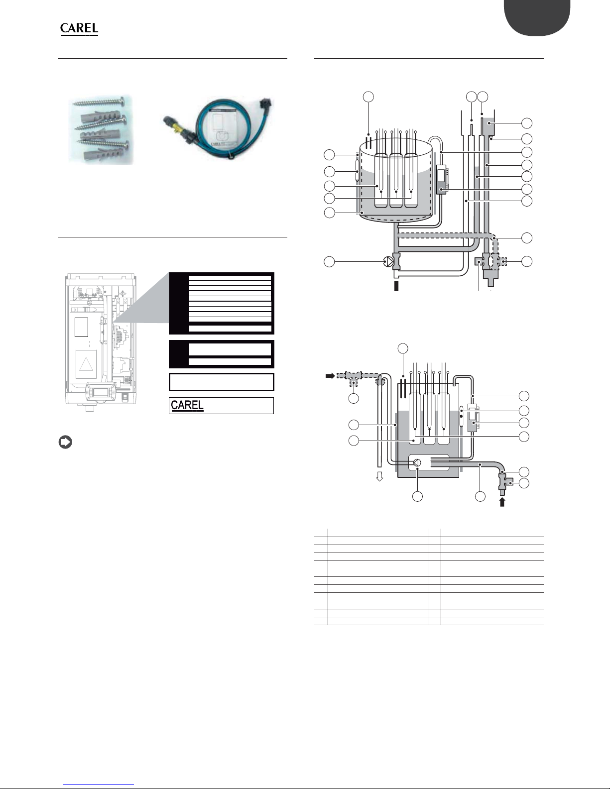
1.10 Water circuit
Models UR002 – UR013
31 2
5
4
7
8
6
9
10
16
17
12
11
19
18
15
14
Fig. 1.k
Models UR020 – UR080
16
1
5
7
12
19
17
14
13
9
18
6
Fig. 1.l
1 Anti-foaming sensor 11 Drain tube tempering (*)
2 Overfi ll diaphragm 12 Drain valve tempering (*)
3 Fill diaphragm 13 Inlet valve
4 Feed tank 14 Drain pump
5
Electrodes for conductivity measurement
15 Anti-adhesive fi lm (**)
6 Equaliser pipe 16 Overtemperature sensors (PTC)
7 Feed pipe 17 Heaters
8 Fill-up pipe 18
Water temperature sensor (NTC)
(**)
9 Level sensor 19 Thermal insulation
10 Overfl ow pipe/drain
(*) for the units equipped with it
(**) for full option modules only

10
!
ENG
“heaterSteam” +0300080EN - rel. 1.0 - 27.04.2016
1.11 Layout of models UR002 – UR0013
Fig. 1.m
Key:
1 Solid state relay (SSR) 20
Level sensor
A Green LED: normal operation
B Yellow LED: fi ll
C Red LED: minimum level
2 Motor protector (THP)
3 Fuse carrier (F1, F2)
4 Contactor
5 Transformer
6 Electronic controller 21 Fastening strap
7 Power cable terminal block 22 Heater
8 Pump fuse (F3) 23 Drain pump
9 RF interference suppressor (where envisaged) 24 Fill valve
10 Power cable gland 25 Drain tempering valve (where envisaged)
11 Fan control board 26 Feedwater tank
12 Auxiliary cable glands 27 SSR thermal protector (Klixon)
13 Cooling fan 28 X1-X2 (prepared for ventilated steam distributors connections)
14 ON/OFF switch 29 X3-X4 (prepared for external drain tempering valve) - where envisaged
15 Drain 30 Drain pump relay
16 Display
17 NTC probe socket
18 Boiler
19 Warning label

11
1
10
11
ENG
“heaterSteam” +0300080EN - rel. 1.0 - 27.04.2016
1.12 Layout of models UR020 – UR0080
Fig. 1.n
Key:
1 Display 20 Drain tempering valve (where envisaged)
2 SSR thermal protector (Klixon) 21 Drain tempering inlet (where envisaged)
3 Cooling fan 22 Level sensor
4 Solid state relay (SSR) 23 Boiler
5 Heater fuses (where envisaged) 24 Drain pipe
6 Contactor 25 Heater
7 Motor protector (THP) 26 Boiler thermal protector (Klixon)
8 NTC probe socket 27 Foam detection sensor
9 Transformer 28 Water fi ll
10 Control board 29 Drain pump relay
11 Fuse carrier (F1, F2, F3) 30 X3-X4 (prepared for external drain tempering valve) - where envisaged
12 Power cable terminal block
13 RF interference suppressor (where envisaged)
14 Power cable inlet
15 ON/OFF switch
16 Drain pump
17 Drain collection tank ( 19 mm)
18 Drain
19 Fill valve

12
ENG
“heaterSteam” +0300080EN - rel. 1.0 - 27.04.2016
2. HYDRAULIC CONNECTIONS
Important: before making the water connections disconnect the
humidifi er from the power supply.
Models UR002..UR013 Models UR020...UR080
1
1
3
3
4
4 7
5
6
6
2
2
4
5
Fig. 2.a
WATER CONNECTIONS:
1. install a manual valve upstream (to cut off the water supply);
2. connect the humidifi er to the water supply. For UR002...UR013 models,
use a fl exible pipe 3/4’’G connection. For UR020...UR080 models
connect the fl exible pipe with the non-return valve (supplied - code
FWHDCV0003), to avoid the water inside the humidifi er making
contact with the one in the mains;
3. install a mechanical fi lter to retain any solid impurities (connect
downstream with respect to the tap.
4. connect a section of pipe for draining (resistant to temperatures of
100 ° C (212 ° F)) and with a minimum internal diameter of 40 mm
(1.6 in) for models UR002-UR013 and 50 mm (2 in), for models UR020
UR080;
5. provide a funnel to ensure continuity interruption in the drain piping;
6. connect a P-trap to prevent the return of odours;
7. for models UR020...UR080: connect a drain pipe from the tank to
the bottom of the humidifi er (this can run into the funnel used for
draining).
8. for drain tempering versions, water temperature will be 60°C (140°F)
with temperature is max 25°C (77°F) guaranteed.
Caution:
• once the installation is complete, fl ush the supply pipe for about
30 minutes by carrying water directly in the drain and without
introducing it into the humidifi er. This will eliminate any waste or
processing residues that could clog the inlet valve and/or cause foam
when boiling water;
• the drain pipe must run vertically downwards at least 30 cm (fi gure 2.a)
to prevent the return of steam.
Set up for water connections:
Models UR002..UR013 Models UR020...UR080
B
A
A
D
B
C
Fig. 2.b Fig. 2.c
Key:
A Supply water inlet
B Drain water outlet
C bottom tank drain water outlet (only for models UR020-UR080)
D Drain tempering inlet

13
ENG
“heaterSteam” +0300080EN - rel. 1.0 - 27.04.2016
Water connection heights:
Drain / Fill
Models UR002…UR013 (view from below):
Fig. 2.d
mm (in)
D 75 (2.95) E 62 (2.44)
D’ 126 (4,96) E' 116 (4.57)
Water fi ll Water fi ll Water drain Water drain
Models UR020…UR080 (left side view):
L’
K
L
L”
I’
I
I”
Fig. 2.e
mm (in)
l 50 (1.96) L' 230 (9.0)
l' 120 (4.72) L” 54 (2.1)
l" 20 (0.78) J 132(5.2)
L 122 (4.8) K 571(22.5)
Water fi ll Water fi ll Water drain Water drain
Steam exhaust and condensate drain
Models UR002…UR013 (top view):
A1
A2
A3
Fig. 2.f
size mm (in) Models UR002-UR013
F 126.7 (5)
F' 224 (8.8)
G 137.9 (5.4)
G' 21.7 (0.85)
A1 Steam outlet
A2 Juncture for the steam distributor condensate drain pipe
A3 Fan head power cable passageway (ancillary)
Models UR020…UR080 (top view):
B1
B2
PP
Fig. 2.g
size mm (in) Models UR020...UR040 Models UR053-UR080
M 172 (2.0) 172 (6.8)
M' 31 (1.2) 52 (2.0)
N 273 (10.7) 260 (10.2)
N' --- 190 (7.4)
N" 46 (1.8) 52 (2.0)
P 60 (2.4) 60 (2.4)
B1 Set up for steam distributor condensate drain pipe
B2 Steam outlet

14
ENG
“heaterSteam” +0300080EN - rel. 1.0 - 27.04.2016
2.1 Supply water
The supply water for the electric heater humidifi er must not be corrosive,
must not emit bad odours, and must not contain too much lime to
avoid excessive deposits. The water, supplied from mains of drinking
water or demineralised water, must have the following characteristics:
LIMIT VALUES FOR THE HEATER HUMIDIFIER WATER
Min Max
Specifi c conductivity at 20°C /68°fH σ20 - μS/cm 0 1500
Total dissolved solids TDS – mg/l (1) (1)
Fixed residual at 180°C/ 356°fH TDS – mg/l (1) (1)
Hydrogen ion activity pH 6 8.5
Total hardness TH– mg/l CaCO3 0 (2) 400
Temporary hardness mg/l CaCO3 0 (3) 300
Chlorides ppm Cl = 50(4)
Iron + Manganese mg/l Fe+Mn = 0.2
Silica mg/l SIO2 = 20
Residual Chlorine mg/l Cl- = 0.2
Calcium sulphate mg/l CaSO4 = 100
Metallic impurities mg/l 0 0
Solvents, diluents, detergents, lubricants mg/l 0 0
Tab. 2.a
1. Values depending on the specifi c conductivity; in general: TDS ≈0,93 * σR, 20
°C; R180 ≈0,65 * σR , 20 °C;
2. Not lower than 200% the content of chloride in mg/l Cl- ;
3. Not lower than 300% the content of chloride in mg/l Cl- ;
4. It could be necessary to intervene on the drain rate to avoid a concentration
in the boiling water higher than 300 mg/l Cl-;
For particularly aggressive water (conductivity <1 μS/cm), use titanium heaters
(heaterSteam titanium model).
Important: treating the water with water softeners or
polyphosphates dispensers is not allowed; it allows for reduced
maintenance but favors the concentration of dissolved salts in the
water in the cylinder, and possible operation irregularities due to the
formation of foam. Should this be impossible to avoid, it requires
dilution with ordinary mains water in such a quantity as to guarantee at
least 60% of its initial hardness value, and not less than 5°f. Water
treatment with reverse osmosis demineralisers is allowed.
Not recommended:
1. the use of well water, industrial water or water from cooling circuits
and, in general, water which may be chemically or bacteriologically
contaminated;
2. the addition to the water of disinfectants or anticorrosion
compounds, as these may cause irritation.
Note: no relationship can be proven between water hardness
and conductivity; nonetheless, as an indication only, water with a
hardness of 40°f should have a conductivity of approximately 900-1000
mS/cm a 20 °C.
2.2 Drain water
• contains the same substances dissolved in the supply water, but in
larger amounts;
• it can reach a temperature of 100 °C (212° F);
• it is not toxic and can be drained in the white waters collection
system.
3. for drain tempering versions, water temperature will be 60°C (140°F),
with temperature is max 25 °C guaranteed.
Important: completely demineralised water is aggressive. For
connection to a water system with fully demineralized water use
only installation items made of plastic resistant to chemicals (eg.
Polypropylene) or stainless steel.
15
ENG
“heaterSteam” +0300080EN - rel. 1.0 - 27.04.2016
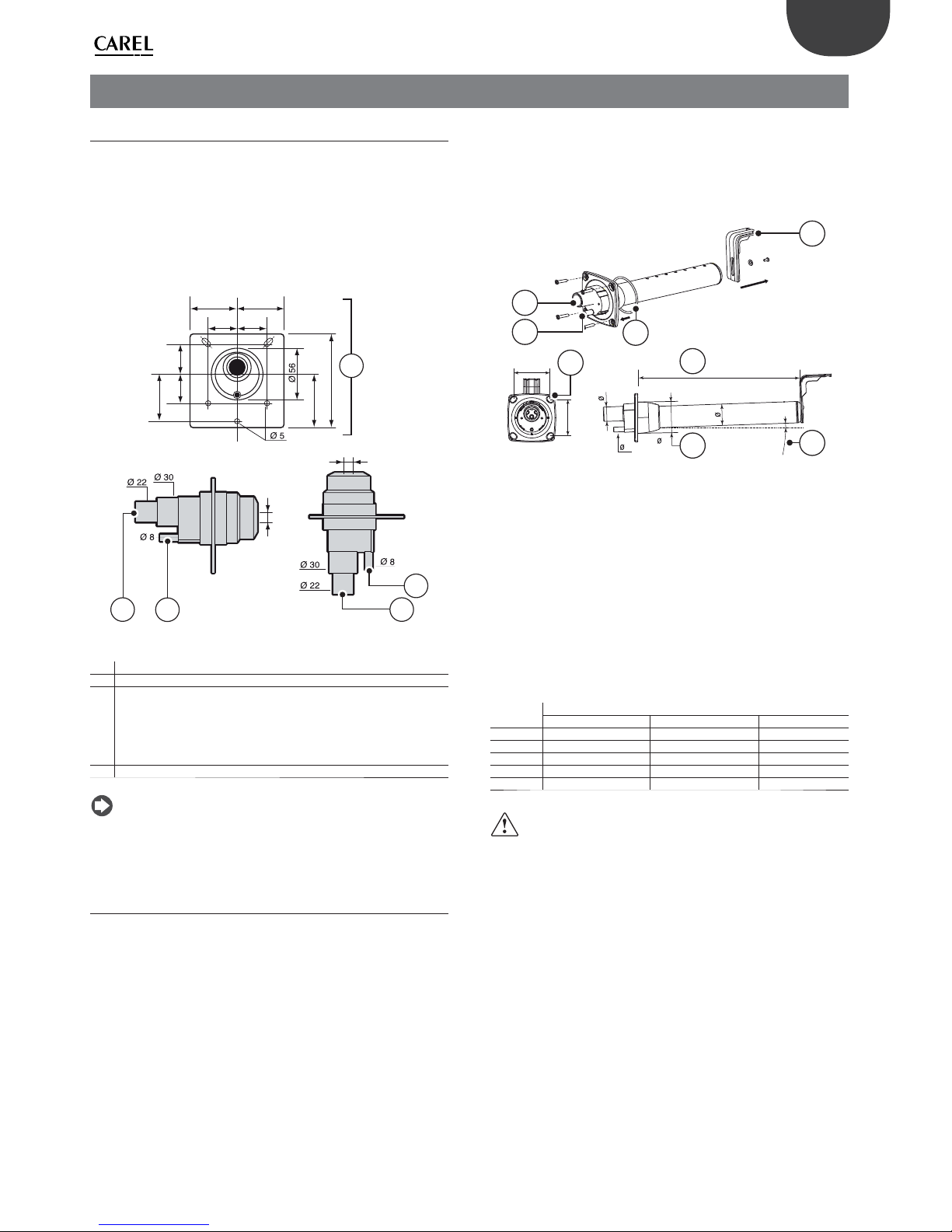
3. STEAM DISTRIBUTION
3.1 CAREL steam nozzles (SDPOEM00**)
Compact steam distributors for small ducts or applications such as steam
baths. They can be mounted either horizontally or vertically (steam
exhaust facing upwords).
Mounting instructions (see fi gure):
1. drill a series of holes in the wall of the pipe, using the drilling jig of
the distributor;
2. insert the distributor;
3. fasten the fl ange of the distributor using 4 screws.
31,5
50 50
31,5
50
31,531,5
57,5
100
C
C
B
AA
B
D
Fig. 3.a
Key:
A. steam inlet
B. condensate drain
C.
steam outlet
The hole dimensions vary depending on the distributor model:
• model SDPOEM0000: hole to be drilled manually,
up to 30 mm (1.2 in) diameter;
• model SDPOEM0012: hole diameter 12 mm (0.5 in);
• model SDPOEM0022: hole diameter 22 mm (0.9 in);
D. drilling jig
Note: if using steam hoses with an inside diameter of 30 mm (1.2 in),
remove the 22 mm (0.9 in) inlet section from the steam nozzle.
3.2 CAREL linear distributors for air ducts or
AHUs (DP***DR0)
The steam distributors for AHU or duct applications deliver steam along
their entire length in order to ensure the shortest not-wetting distance.
The distributor should be chosen based on the maximum required
capacity, the dimensions of the AHU/duct and the outlet diameter of
the humidifi er it is connected to. Install far from any obstacle (curves,
ramifi cation, section changes, grilles, fi lters, fans).
Minimum distance between distributor and obstacle: 1…1.5 m (3.3…4.9 ft).
Increase distance in case of:
1. increase in speed of the air in the duct;
2. turbulence decrease.
Mounting instructions (see fi gure):
• drill a series of holes in the wall of the pipe, using the drilling jig of the
distributor (found in the packaging of the distributor);
• insert the distributor with the steam outlet holes facing upwards;
• fasten the fl ange of the distributor using 4 screws.
B
Y
X
A
X
°2
L
5
4
3
2
1
9
6
8
Fig. 3.b
Key:
1. L-shaped mounting bracket (where applicable)
2. fl ange gasket
3. steam inlet (ØA)
4. condensate drain (ØB)
5. fl ange screw (see instructions sheet that comes with the distributor)
6. L = length (depending on the model of distributor, see paragraph
“Linear distributors” )
7. tilt angle (about 2 °) for condensate drain
8. diameter of the hole in the wall (ØY)
Size in mm (in)
linear distributors from CAREL
DP***D22R0 DP***D30R0 DP***D40R0
ØA 22 (0.9) 30 (1.2) 40 (1.6)
ØB 10 (0.4) 10 (0.4) 10 (0.4)
ØY 58 (2.3) 68 (2.7) 89 (3.5)
Ø 35 (1.4) 45 (1.8) 60 (2.4)
X 68 (2.7) 77 (3.0) 99 (3.9)
Tab. 3.a
Caution:
1. mount the distributor slightly tilted (at least 2°, to facilitate the
condensate discharge);
2. the L-shaped supports (see element 1 Fig. 3. b) is supplied with steam
distributors models from DP085* to DP205*. For shorter lengths the
bracket can be supplied as optional (code 18C478A088).

16
ENG
“heaterSteam” +0300080EN - rel. 1.0 - 27.04.2016
3.3 CAREL blowers for room installation
(VSDU0A*, VRDXL*)
Steam distributors for installation in rooms. These come with a fan
to assist steam absorption. The VSDU0A* blowers can be used on
humidifi ers with fl ow-rates up to 18 kg/h (39.7 lb/h), i.e. models UR002…
UR013. They can be connected to the top of the humidifi er, or separately
in a remote position using the fastening support VSDBAS0001 (see Fig.
3.c). These distributors have a power supply inside the electrical panel
(24 Vac, Terminals X1, X2).
A
B
C
D
E
F
G
Fig. 3.c
A > 0,5 m (>19.6”) E > 0,5 m (>19.6”)
B > 5 m (>196.8”) F > 5 m (>196.8”)
C > 2,1 m (>82.6”) G > 1 m (>39.4”)
D > 1 m (>39.4”)
Caution: in order to achieve proper steam distribution observe
the distances indicated in the fi g. above.
For the humidifi ers larger than 18 kg/h, the are ventilated steam
distributors code VRDXL00000 with 230 Vac power supply, external
power supply (maximum capacity 45 kg/h). The distributors are designed
for installation in a remote position, and require two steam hoses with a
30 mm diameter, c
connected to a “Y” adapter (available as accessories, contact Carel for
details on the product code).
C > 1,8 m (>70.8”) E > 0,9 m (>35.4”)
D > 1,2 m (>47.2”) F > 3 m (>118.9”)
G > 1,2 m (>47.2”)
In this case, terminal J19.1 on the control board is used as a voltage-free
contact (normally open when there is no production - SSR OFF). This
contact has a maximum rating of 2 A.
3.4 Steam transport pipe
• use CAREL fl exible hoses (max 4 m long, see section “Models of steam
conducting pipes”);
• avoid the formation of pockets or traps (cause of condensate
accumulation)
• avoid choking the pipe with sharp bends or twists.
• Use metal clamps to fasten the ends of the pipe to the connections
on the humidifi er and the steam distributor, so that they do not come
loose as a result of the temperature.
• avoid strains which include mechanical stress on the cylinder steam
outlet tailpiece
3.5 Condensate drain pipe
During the operation of the humidifi er part of the steam can condense,
causing effi ciency loss and noise (gurgling).
To drain the condensate connect to the base of the distributor a discharge
pipe with a water trap and a minimum slope of 5° (see fi g.3.d).
CAREL condensate drain pipes: code 1312368AXX (ø 10mm) (CHOSE00516 (5/16”) for North American market) for DP* series linear
steam distributors; code 1312353APG (ø 7mm) - (CHOSE0038 (3/8”) for
North American market) for steam blowers and nozzles.
Caution: the condensate drain pipe trap must be fi lled with water
prior to turning on the humidifi er.
Below are show some installation examples of the steam transport and
condensate drain pipes:
All the UR models
>5°
D> 200mm (8”)
>5°
R> 300mm (12”)
H ≤ 2 m (7.8”)
Fig. 3.d
Models UR002...UR013 (1), condensate drain connection with return
to fi ll tank:
>20°
>5°
1
D> 200mm (8”)
R> 300mm (12”)
Fig. 3.e
Models UE020...UR080 (1) extend the pipe inside the humidifi er up to
the base tank.
>20°
>5°
1
D> 200mm (8”)
R> 300mm (12”)
Fig. 3.f

17
ENG
“heaterSteam” +0300080EN - rel. 1.0 - 27.04.2016
All the UR models
NO
Fig. 3.g
SI
R>300mm (12”)
D> 200mm (8”)
R>300mm (12”)
NO
NO
D> 200mm (8”)
Fig. 3.h
3.6 Outlet pressure limits
The backpressure at the boiler outlet, either positive or negative, depends
both on the relative pressure in the duct/AHU and the pressure drop in
the steam pipe, due to bends or adapters, and the steam distributor.
Carel steam transport pipes have a pressure drop of around 150 Pa/m
(0.021psi) (respecting the maximum fl ow-rate recommended by Carel).
Carel DP* series linear distributors have a pressure drop of around 25 Pa
(0.003psi) (respecting the maximum fl ow-rate recommended by Carel).
Considering these values, the boiler outlet pressure must be:
boiler outlet pressure > 150 [Pa/m] * steam pipe length [metres] + 25 [Pa]
DP + pressure in duct/AHU [Pa]
Boiler outlet pressure values for heaterSteam:
UR002…R013 UR020…UR080
pressure limits at boiler outlet
Pa (PSI)
0 to 1500 (0 to
0.218)
0 to 2000 (0 to
0.290)
Note: a pressure of around -200 Pa (-0.029 psi) at the boiler outlet
corresponds to around 20 mm (0.78”) of water inside the boiler (for all
sizes).

18
ENG
“heaterSteam” +0300080EN - rel. 1.0 - 27.04.2016
4. ELECTRICAL CONNECTIONS
4.1 Wiring provisions
Models UR002-UR013
Outside, bottom view Inside, top view
3
1
1
3
Fig. 4.a Fig. 4.b
Models UR20-UR80
Outside, side view
1
3
2
Fig. 4.c
Key:
1. power supply cable inlet;
2. inlet (after removing the knock-out) for other uses;
3. probe cables inlet (after removing the knock-outs).
4.2 Power cable connection
Before making the connections, make that the unit is disconnected from
the mains power supply: move the main system switch and humidifi er
switch to OFF).
Important: the humidifi er ON/OFF switch disconnects power
only to the electronic controller, and not the other devices, which
therefore remain powered.
Check that the unit’s power supply voltage corresponds to the rated value
shown inside the electrical panel. Remove the front panel as explained in
chap. 1.
To enter the power and probe cables, see the follow the procedures
described below:
Models UR002-UR013
1. unscrew the screws and remove the cover (A);
2. if necessary, cut the top part of the conical cable gland (B) and insert
the power cable;
3. connect the electrical wires to the terminal block, reposition the
cover and fasten it using the screws;
To attach the probe cable:
4. remove the knock-out (C) and unscrew the screws;
5. insert the probe cable through the opening created: then fasten the
cable using the screws.
A
B
1
2
GND
L
N
3
Fig. 4.d Fig. 4.e
GND
L
N
C
4
GND
L
N
5
Fig. 4.f Fig. 4.g
Models UR020-UR080
1. identify the rubber cable gland (A) on the right side of the unit and
insert the power cable;
2. inside the electrical panel: unscrew the cable gland (B), connect the
wires to the terminal block and tighten the screws again to fasten
the cable.
GND
L1
L2
L3
B
A
Fig. 4.h
The humidifi er power line must be fi tted by the installer with a disconnect
switch and fuses to protect against short circuits. The table shows the
recommended sizes of the cable and fuses; nonetheless, these data are
purely indicative and, if diff erent from local standards in force, the latter
must prevail.
Note: to avoid unwanted interference, the power cables should
be kept separate from the probe signal cables.
Important: connect the yellow-green wire to the earth terminal
(GND).

19
ENG
“heaterSteam” +0300080EN - rel. 1.0 - 27.04.2016
4.3 Control board
The control board (S) is inside of the electrical panel in the wall dividing.
The auxiliary connections (probes, remote terminal, alarm) are made by
inserting the cables form the outside into the electrical panel.
To do this, use cables gland located on the base of the unit to the plug-in
screw terminals on the control board.
UR002-UR013 UR020-UR080
6
6
Fig. 4.i Fig. 4.j
M2M9
12 1 123 123452121122123456
J17C
2 1
J17L J23 J24 J19J20J3 J16 M3 J18
2 1
J21
M8 M1 M5 M6M12
1 1234567821132 31221212
main probe
ext. regulator
GND
GND
Remote
ON/OFF
limit probe
12Vdc
Control signal
Ethernet
GND
RS485 Serial
L+
L-
Alarm
relay
NO
NC
CNOC
Unit
status
relay
Fig. 4.k
Key:
Terminal Function Electrical specifi cations
M1 M1.1 GND (G0)
M1.2 Controller power supply 24Vac +10%/-15% 50/60Hz
M2 M2.1 Main room probe signal
input or signal from external
controller
0/1V, 0/10V, 2/10V, 0/20mA,
4/20mA, NTC 10 kΩ a 25 °C
M2.2 GND
M2.3
Probe power supply (+G)
+12 Vdc, maximum current that
can be delivered 50 mA; Protection against short-circuits
M2.4
Digital input for backup/
rotation function
Maximum current output: 5 mA;
Maximum voltage with contact
open: 13 Vdc
M2.5 Limit humidity probe signal
input
0/1V, 0/10V, 2/10V, 0/20mA,
4/20mA, NTC
M2.6 GND
M2.7 GND
M2.8
Remote on/off contact
digital input
Maximum current output: 5 mA;
Maximum voltage with contact
open: 13 Vdc
M3 M3.1
Fieldbus
Tx/Rx-
M3.2 Tx/Rx+
M3.3 GND
M5 M5.1 Unit status contact (NO)
250 Vac; 2 A with resistive load;
2 A with inductive load
M5.2 Unit status contact
common
M6 M6.1 Alarm common
250 Vac; 2 A with resistive load;
2 A with inductive load
M6.2 NC alarm contact
M6.3 NO alarm contact
Terminal Function Electrical specifi cations
M8 M8.1 Production request analo-
gue output
Output voltage range: 0-10 V
max 10 mA
M8.2 GND
M9 M9.1 Backup and rotation contact
common
250 Vac; 2 A with resistive load;
2 A with inductive load
M9.2 Backup and rotation NO
contact
M11 Ethernet port
M12 M12.1
BMS 485
Tx/Rx-
M12.2 Tx/Rx+
M12.3 GND
Earth connection
J18 pLAN/display terminal
J19 J19.1 Auxiliary/blower contact
(NO)
250 Vac; 2 A with resistive load;
2 A with inductive load
J19.2 Auxiliary/blower contact
common
USB Port (type A)
Ethernet RJ45 Port
Tab. 4.b

20
ENG
“heaterSteam” +0300080EN - rel. 1.0 - 27.04.2016
4.4 Operating and control principles
Before describing each electrical connection on heaterSteam, below are
some fundamental aspects regarding the control of steam humidifi ers.
4.4.1 Operating principle of a heater humidi er
HeaterSteam is an isothermal steam humidifi er whose technology uses
heaters immersed in a cylinder or boiler fi lled with water. This may be
mains water or demineralised water. The heat generated by the heaters
increases the water temperature up to around 100°C (212°F). The use
of demineralised water ensures long cylinder and heater life, as virtually
no scale builds up. On the other hand, if using mains water, some of the
minerals dissolved in the water accumulate in the cylinder as solids with
diff erent compositions. To prevent this from occurring, when the water
conductivity in the cylinder exceeds a certain value, some of the water is
periodically drained and replenished, thus diluting the water. In models
where featured, the drain water is mixed with mains water so as to not
exceed the maximum temperature allowed by national and local standards
in force (drain tempering function). The steam generated has a temperature
of around 100°C (212°F) and minimal positive pressure (unpressurised
steam). It is virtually free of minerals and germs. Steam production is
controlled with ON/OFF logic or with continuous modulation from 0% to
100% of rated output, using solid state relays (SSR); the control logic in this
case is PWM (i.e. pulse width modulation) with a programmable time base.
4.4.2 Control principles
The appliance is fi tted with solid state relays (SSR), meaning steam
production is continuously adjustable based on demand, in one of the
following modes.
4.4.3 ON/OFF control
Operation is all or nothing, and is activated by an external contact; the
maximum percentage of unit production can be set.
4.4.4 Proportional to an external signal (modulating
control)
Steam production is proportional to the value of an external signal Y,
(selectable by programming one of the following standards: 0 to 1 Vdc; 0
to 10 Vdc; 2 to 10 Vdc; 0 to 20 mA; 4 to 20 mA). The maximum production
Pmax corresponds to the maximum value of the external signal Y and
will be the humidifi er’s rated production. The activation hysteresis hy is
settable by the user and refers to the external signal Y.
Pmax
Steam_Pr
Pmin
OFF ON
0%
hy 2xhy 100%
Y
Y= 0…1Vdc
0…10Vdc
2…10Vdc
0…20mA
4…20mA
Fig. 4.l
Key:
Steam_pr Steam production Y External signal
P0 Max production hy Activation hysteresis
Pm Min production
Note: the graph shown above applies when the pre-heating
function is disabled.
4.4.5 Autonomous control with humidity probes
Steam production is related to the % rH reading made by the relative
humidity probe and increases as the value read deviates from the set
point St. Maximum production Pmax corresponds to the case where the
humidity value, read by the probe, is BP away (proportional band) from
the set point. The activation hysteresis hy is settable by the user.
Pmax
Steam_Pr
Pmin
OFF
ON
St
hy
BP
%rH
Fig. 4.m
Key:
Steam_pr Steam production Y External signal
P0 Max production hy Activation hysteresis
Pm Min production
To check that the relative humidity measured by the transducer is within
certain preset values, two alarm thresholds can be set in autonomous
control:
• high relative humidity alarm threshold;
• low relative humidity alarm threshold.
When these thresholds are exceeded, an alarm is activated by closing the
corresponding relay contact on the main control board.
4.4.6 Autonomous control with relative humidity
transducer and outlet limit probe
In this case too, the controller modulates steam production based on the
% rH measured by the main relative humidity transducer, while limiting
production if the humidity measured by a second limit transducer,
located in the air duct downstream of the steam distributor, approaches
the maximum desired value. Consequently, to prevent the relative
humidity of the outlet air from exceeding a value that is considered
excessive, the control module with autonomous control and limit
transducer can be set with a high relative humidity alarm threshold.
When this threshold is exceeded, the alarm is activated by closing the
corresponding relay contact on the main control board. The limit probe
allows steam production to be modulated depending on the specifi c set
limit diff erential.
4.4.7 Application for steam baths
In applications for steam baths, in which the control probe measures
temperature rather than humidity, the same rules apply as for
autonomous control with probe.
By setting control to temperature, the humidifi er will continue to produce
steam until reaching the desired set point temperature inside the steam
bath, and consequently the desired saturation of the air (fog eff ect).
Recommended CAREL transducer: ASET030001 or ASET030000, or NTC
probes UEKNTC0*.

21
ENG
“heaterSteam” +0300080EN - rel. 1.0 - 27.04.2016
4.5 Steam production control signals
The humidifi er features solid state relays (SSR) for modulating steam
production, and consequently capacity may range from 1 to 100% of output,
depending on control requirements. The humidifi er can be connected via
RS485 serial or Ethernet connection to a remote supervisor. Depending on
the type of signal used, steam production can be enabled and/or managed
in diff erent ways (ON/OFF or modulating).
Important: the probe inputs are protected against short-circuits,
and the maximum current delivered (M2.3) is 50 mA. Despite this, it is
recommended to confi gure the “Control type” before connecting the
probes to the terminals.
To help users confi gure the unit, a screen index is shown at the top right of the
display. The screen index corresponds to the sequence in each menu in order
to reach the specifi c page.
Screen
index
Fig. 4.n
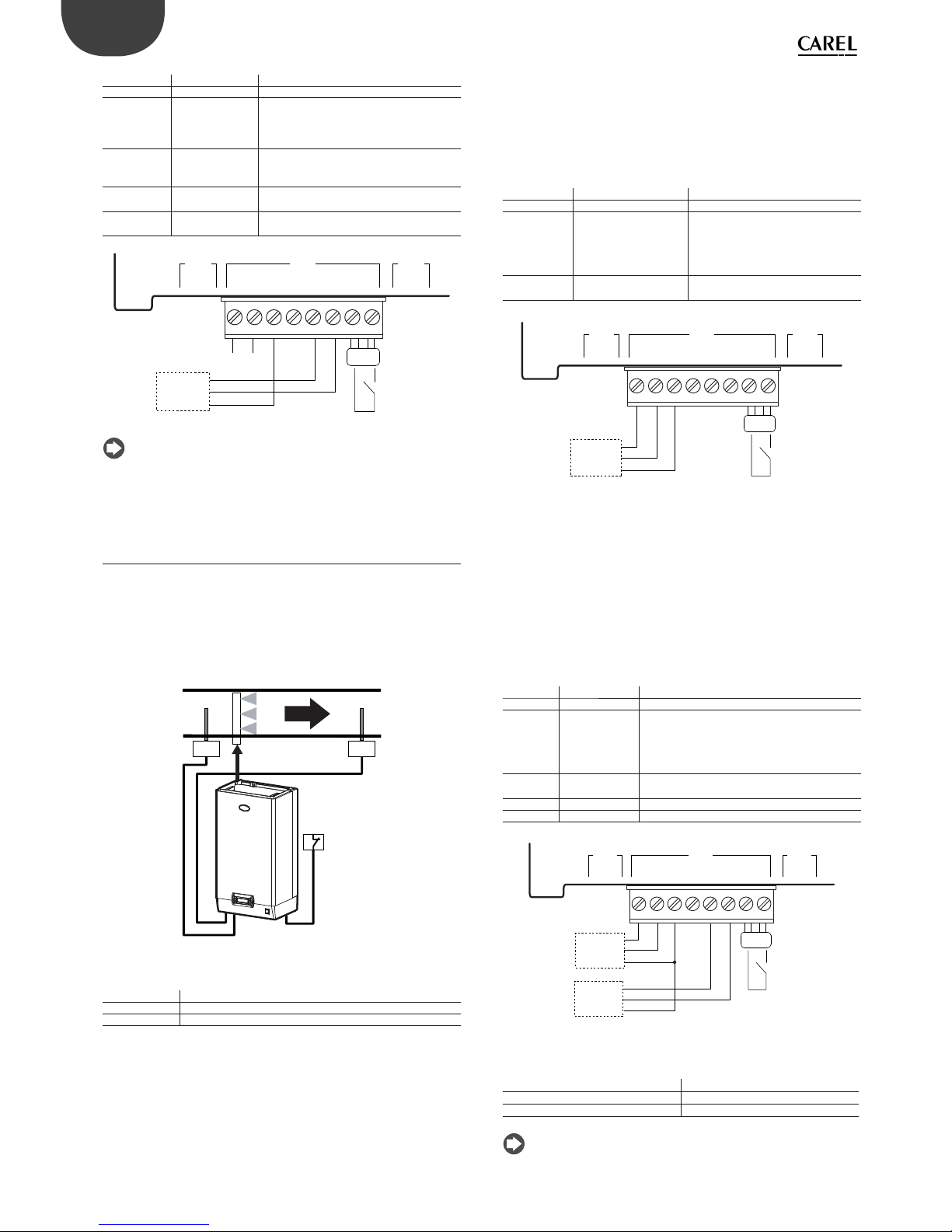
Steam production can be started by:
HUMIDISTAT (ON/OFF operation):
• connect terminals M2.1 and M2.2 (production request) to a humidistat;
• short-circuit terminals M2.7 – M2.8 (jumper) to enable production;
• to enable ON/OFF operation, set:
Screen index Screen description Parameter
Ea01 Control type External ON/OFF signal
Ea04 Maximum production 0-100% of rated production
M2M9 M8
1 12345678212
Fig. 4.o
_________________________________________________________
HUMIDISTAT and REMOTE CONTACT (ON/OFF operation)
• connect terminals M2.1 and M2.2 (production request) to a humidistat;
• connect inputs M2.7 – M2.8 (enable) to a remote contact (e.g.: switch,
timer,...);
• to enable ON/OFF operation, set:
Screen index Screen description Parameter
Ea01 Control type External ON/OFF signal
Ea04 Maximum production 0-100% of rated production
M2M9 M8
1 12345678212
Fig. 4.p
Steam production can be enabled and controlled by:
EXTERNAL PROPORTIONAL CONTROLLER (modulating operation)
• short-circuit terminals M2.7 – M2.8 (jumper) to enable production;
• connect terminals M2.1 and M2.2 (production request) to an external
controller;
• to enable control, set:
Screen ind. Screen desc. Parameter
Ea01 Control type proportional to external signal
Ea03 Proportional band Set: Hysteresis (0-100%)
Minimum production (0-100%)
Maximum production (0-100%)
Ec01 Main probe type Select from: 0-1V, 0-10V, 2-10V, 0-20mA,
4-20mA
OUT
REF
M2M9 M8
1 12345678212
Fig. 4.q
_________________________________________________________
EXTERNAL PROPORTIONAL CONTROLLER and REMOTE CONTACT
(modulating operation)
• connect terminals M2.1 and M2.2 (production request) to a humidistat;
• connect inputs M2.7 – M2.8 (enable) to a remote contact (e.g.: switch,
timer,...);
• to enable control, set:
Screen ind. Screen desc. Parameter
Ea01 Control type proportional to external signal
Ea03 Proportional band Set: Hysteresis (0-100%)
Minimum production (0-100%)
Maximum production (0-100%)
Ec01 Main probe type Select from: 0-1V, 0-10V, 2-10V, 0-20mA,
4-20mA
OUT
REF
M2M9 M8
1 12345678212
Fig. 4.r
_________________________________________________________
EXTERNAL PROPORTIONAL CONTROLLER and REMOTE CONTACT
(modulating operation) with LIMIT PROBE
• short-circuit terminals M2.7 – M2.8 (jumper) to enable production;
alternatively connect terminals M2.7 – M2.8 to a remote contact (e.g.:
switch, timer,...);
• connect terminals M2.1 and M2.2 (production request) to an external
controller;
• connect the active limit probe to terminals M2.5, M2.3 (+12Vdc), M2.6
(GND);
• to enable control, set:
22
ENG
“heaterSteam” +0300080EN - rel. 1.0 - 27.04.2016
Screen ind. Screen desc. Parameter
Ea01 Control type prop. to external signal with limit probe
Ea03 Proportional band Set:
Hysteresis (0-100%)
Minimum production (0-100%)
Maximum production (0-100%)
Ea06 Limit probe Set:
Set point (0-100 %rH)
Diff erential (0-100%)
Ec01 Main probe type Select from: 0-1V, 0-10V, 2-10V, 0-20mA,
4-20mA
Ec02 Limit probe type Select from: 0-1V, 0-10V, 2-10V, 0-20mA,
4-20mA
OUT
REF
M2M9 M8
1 12345678212
OUT H / T
M
+ (G)
Fig. 4.s
Note: in industrial environments (IEC EN61000-6-2) the signal cables
leaving the unit must not exceed 30 m (98’) in length: steam production
signal cable (terminals M2.1, M2.2), digital remote on/off input (terminals
M2.7, M2.8) and shielded cable for RS485 communication.
4.6 Control with humidity probes
The main control board, connected to a room humidity probe, manages
steam production based on the humidity measured. A second outlet
humidity limit probe can also be connected: with this confi guration,
typical of air handling units, the main control board continues managing
steam production according to the humidity requirement, however
production is limited according to the relative humidity measured in the
outlet duct.
HP HLP
Remote
Contact
Fig. 4.t
Key:
HP Humidity control probe (intake/room humidity probe)
HLP Limit humidity probe (outlet humidity probe)
Remote Contact Remote contact
CONTROL WITH ONE HUMIDITY PROBE
• short-circuit terminals M2.7 – M2.8 (jumper) to enable production;
alternatively connect terminals M2.7 – M2.8 to a remote contact (e.g.:
switch, timer,...);
• connect the main active room probe to terminals M2.1, M2.2 (GND)
and M2.3 (+12Vdc);
• to enable control, set:
Screen ind. Screen desc. Parameter
Ea01 Control type one humidity probe
Ea05 Modulating control Set:
humidity set point (0-100 %rH)
diff erential (2-20%rh)
Minimum production (0-100%)
Maximum production (0-100%)
Ec01 Main probe type Select from: 0-1V, 0-10V, 2-10V,
0-20mA, 4-20mA
M2M9 M8
1 12345678212
OUT H / T
M
+ (G)
Main probe
Fig. 4.u
_________________________________________________________
CONTROL WITH ONE HUMIDITY PROBE AND LIMIT PROBE
• short-circuit terminals M2.7 – M2.8 (jumper) to enable production;
alternatively connect terminals M2.7 – M2.8 to a remote contact (e.g.:
switch, timer,...);
• connect the main active room probe to terminals M2.1, M2.2 (GND)
and M2.3 (+12Vdc);
• connect the active limit probe to terminals M2.5, M2.3 (+12Vdc), M2.6
(GND);
• to enable control, set:
Screen ind. Screen desc. Parameter
Ea01 Control type humidity with limit probe
Ea05 Modulating
control
Set:
humidity set point (0-100 %rH)
diff erential (2-20%rh)
Minimum production (0-100%)
Maximum production (0-100%)
Ea06 Limit probe Set point (0-100 %rH)
Diff erential (0-100%)
Ec01 Main probe type Select from: 0-1V, 0-10V, 2-10V, 0-20mA, 4-20mA
Ec02 Limit probe type Select from: 0-1V, 0-10V, 2-10V, 0-20mA, 4-20mA
M2M9 M8
1 12345678212
OUT H / T
M
+ (G)
Main probe
OUT H / T
M
+ (G)
Second probe
Fig. 4.v
The following probes can be connected:
CAREL probes for rooms DPWC111000
for air ducts DPDC110000, DPDC210000
for technical applications DPPC210000, DPPC210000
Note: non-CAREL active probes can be connected to the controller.

23
ENG
“heaterSteam” +0300080EN - rel. 1.0 - 27.04.2016
CONTROL WITH TWO HUMIDITY PROBES
• short-circuit terminals M2.7 – M2.8 (jumper) to enable production;
alternatively connect terminals M2.7 – M2.8 to a remote contact (e.g.:
switch, timer,...);
• connect the main active room probe to terminals M2.1, M2.2 (GND)
and M2.3 (+12Vdc);
• connect the second active probe to terminals M2.5, M2.3 (+12Vdc) and
M2.6 (GND);
• to enable control, set:
Screen ind. Screen desc. Parameter
Ea01 Control type Modulation with two humidity probes
Ea02 Control with 2 probes Set the weight of the two probes (0-100%)
Ea05 Modulating control Set:
humidity set point (0-100 %rH)
diff erential (2-20%rh)
Minimum production (0-100%)
Maximum production (0-100%)
Ec01 Main probe type Select from: 0-1V, 0-10V, 2-10V, 0-20mA, 4-20mA
Ec02 Second probe type Select from: 0-1V, 0-10V, 2-10V, 0-20mA, 4-20mA
The controller will calculate the weighted average between the two
probes. The weight of the two probes can also be set.
M2M9 M8
1 12345678212
OUT H / T
M
+ (G)
Main probe
OUT H / T
M
+ (G)
Second probe
Fig. 4.w
The following probes can be connected:
CAREL probes for rooms DPWC111000
for air ducts DPDC110000; DPDC210000
for technical applications DPPC210000; DPPC210000
Note: non-CAREL active probes can be connected to the controller.
4.7 Control with temperature probes
The controller features independent internal temperature control,
and can be connected to a temperature probe TT (Fig. 4.r). It performs
complete control based on the temperature measured inside the
controlled environment.
TT
Remote
contact
Fig. 4.x
Key:
TT Active temperature probe
Remote Contact Remote contact
CONTROL WITH ONE ACTIVE TEMPERATURE PROBE
• short-circuit terminals M2.7 – M2.8 (jumper) to enable production;
alternatively connect terminals M2.7 – M2.8 to a remote contact (e.g.:
switch, timer,...);
• connect the main active room probe to terminals M2.1, M2.2 (GND)
and M2.3 (+12Vdc);
• to enable control, set:
Screen ind. Screen desc. Parameter
Ea01 Control type one temperature probe
Ea05 Modulating control Set:
temperature set point (0-100 °C) (32-212°F)
diff erential (2-20°C) (3.6-36°F)
Minimum production (0-100%)
Maximum production (0-100%)
Ec01 Main probe type Select from: 0-1V, 0-10V, 2-10V, 0-20mA,
4-20mA
M2M9 M8
1 12345678212
OUT H / T
M
+ (G)
Main probe
Fig. 4.y
_________________________________________________________
CONTROL WITH ONE TEMPERATURE PROBE AND LIMIT PROBE
• short-circuit terminals M2.7 – M2.8 (jumper) to enable production;
alternatively connect terminals M2.7 – M2.8 to a remote contact (e.g.:
switch, timer,...);
• connect the main active room probe to terminals M2.1, M2.2 (GND)
and M2.3 (+12Vdc);
• connect the active limit probe to terminals M2.5, M2.3 (+12Vdc), M2.6 (GND);
• to enable control, set:
Screen ind. Screen desc. Parameter
Ea01 Control type Temperature with limit
Ea05 Modulating
control
Set:
temperature set point (0-100 °C) (32-212°F)
diff erential (2-20°C) (3.6-36°F)
Minimum production (0-100%)
Maximum production (0-100%)
Ea06 Limit probe Set point (0-100 °C/°F)
Diff erential (0-100%)
Ec01 Main probe type Select from: 0-1V, 0-10V, 2-10V, 0-20mA, 4-20mA
Ec02 Limit probe type Select from: 0-1V, 0-10V, 2-10V, 0-20mA, 4-20mA
M2M9 M8
1 12345678212
OUT H / T
M
+ (G)
Main probe
OUT H / T
M
+ (G)
Second probe
Fig. 4.z
The following probes can be connected:
CAREL probes for rooms DPWC111000
for air ducts DPDC110000; DPDC210000
for technical applications DPPC210000, DPPC210000
Note: non-CAREL active probes can be connected to the controller.

24
ENG
“heaterSteam” +0300080EN - rel. 1.0 - 27.04.2016
CONTROL WITH TWO ACTIVE TEMPERATURE PROBES
• short-circuit terminals M2.7 – M2.8 (jumper) to enable production;
alternatively connect terminals M2.7 – M2.8 to a remote contact (e.g.:
switch, timer,...);
• connect the main active room probe to terminals M2.1, M2.2 (GND)
and M2.3 (+12Vdc);
• connect the second active probe to terminals M2.5, M2.3 (+12Vdc) and
M2.6 (GND);
• to enable control, set:
Screen ind. Screen desc. Parameter
Ea01 Control type Temperature (two probes)
Ea02 Control with 2 probes Set the weight of the two probes (0-100%)
Ea05 Modulating control Set: temperature set point (0-100 °C) (32-
212°F)
diff erential (2-20°C) (3.6-36°F)
Minimum production (0-100%)
Maximum production (0-100%)
Ec01 Main probe type Select from: 0-1V, 0-10V, 2-10V, 0-20mA,
4-20mA
Ec02 Second probe type Select from: 0-1V, 0-10V, 2-10V, 0-20mA,
4-20mA
The controller will calculate the weighted average between the two
probes. The weight of the two probes can also be set.
M2M9 M8
1 12345678212
OUT H / T
M
+ (G)
Main probe
OUT H / T
M
+ (G)
Second probe
Fig. 4.aa
The following probes can be connected:
CAREL probes for rooms DPWC111000
for air ducts DPDC110000; DPDC210000
for technical applications DPPC210000, DPPC210000
Note:: non-CAREL active probes can be connected to the controller.
_________________________________________________________
CONTROL WITH ONE NTC TEMPERATURE PROBE (passive)
• short-circuit terminals M2.7 – M2.8 (jumper) to enable production;
alternatively connect terminals M2.7 – M2.8 to a remote contact (e.g.:
switch, timer,...);
• connect the main NTC room probe to terminals M2.1, M2.2;
• to enable control, set:
Screen index Screen description parameter
Ea01 Control type one temperature probe
Ea05 Modulating control Set:
temperature set point (0-100 °C)
(32-212°F)
diff erential (2-20°C) (3.6-36°F)
Minimum production (0-100%)
Maximum production (0-100%)
Ec01 Main probe type Set probe type: NTC
M2M9 M8
1 12345678212
Fig. 4.ab
CONTROL WITH TWO NTC TEMPERATURE PROBES (passive)
• short-circuit terminals M2.7 – M2.8 (jumper) to enable production;
alternatively connect terminals M2.7 – M2.8 to a remote contact (e.g.:
switch, timer,...);
• connect the main NTC room probe to terminals M2.1, M2.2;
• connect the second NTC probe to terminals M2.5, M2.6;
• to enable control, set:
Screen index Screen description parameter
Ea01 Control type Modulation with two temperature
probes
Ea02 Control with 2 probes Set the weight of the two probes
(0-100%)
Ea05 Modulating control Set:
temperature set point (0-100 °C)
(32-212°F)
diff erential (2-20°C) (3.6-36°F)
Minimum production (0-100%)
Maximum production (0-100%)
Ec01 Main probe type Set probe type: NTC
Ec02 Second probe type Set probe type: NTC
The controller will calculate the weighted average between the two
probes. The weight of the two probes can also be set.
M2M9 M8
1 12345678212
Fig. 4.ac
4.8 Alarm contact
The humidifi er controller is fi tted with a relay contact for remote signalling
of one or more faults or alarms. The alarm contact (250 Vac; max capacity: 2
A resistive - 2 A inductive) is connected to terminals M6.1, M6.2 and M6.3.
M1 M5 M6M12
132 31212 12
NC
NO
CO
L
N
Fig. 4.ad
M6.1 CO - Alarm common
M6.2 NC - NC alarm contact
M6.3 NO - NO alarm contact

25
ENG
“heaterSteam” +0300080EN - rel. 1.0 - 27.04.2016
4.9 Unit status contact / maintenance prealert
The humidifi er controller is fi tted with a relay contact for remote signalling
of unit status. The contact is normally open. When the unit is producing
steam, the contact is closed. The unit status contact (250 Vac; max capacity:
2 A resistive - 2 A inductive) is connected to terminals M5.1, M5.2.
M1 M5 M6M12
132 31212 12
NC
NO
Fig. 4.ae
M5.1 Unit status contact (NO)
M5.2 Unit status contact common
Contact M5.2 is confi gured by default as the unit status contact. The same
relay can also be confi gured as a maintenance pre-alert, proving a signal
before the actual maintenance alarm is activated, allowing maintenance
to be scheduled. See paragraph “7.2.7 Cylinder operating hours” for
further details on confi guring the warning.
To confi gure digital output M5.2 as a maintenance pre-alert, set:
Screen index Screen description parameter
Eb07 Digital output M5.2 Maintenance pre-alert
Ea07 Cylinder operating hours Set the warning parameter
(hours)
4.10 Production request analogue output
The humidifi er controller is fi tted with an analogue output (0-10 V signal)
that refl ects the production request.
The production request output (0-10 V max 10 mA) is connected to
terminals M8.1, M8.2.
0-10V
M2M9 M8
1 12345678212
Fig. 4.af
M8.1 Production request analogue output
M8.2 GND
IMPORTANT WARNINGS: to avoid unbalanced control, the earth
of the probes or external controllers must be connected to the unit
controller’s earth.
4.11 Final checks
The following conditions represent correct electrical connection:
1. mains power to the humidifi er corresponds to the voltage shown on
the rating plate;
2. the fuses installed are suitable for the line and power voltage;
3. a mains disconnect switch has been installed so as to be able to
disconnect power to the humidifi er;
4. the humidifi er has been correctly earthed;
5. the power cable is fastened to the tear-proof cable clamp;
6. terminals M2.7, M2.8 are jumpered or connected to an enabling
contact;
7. if the humidifi er is controlled by an external controller, the signal
earth is electrically connected to the controller earth.
5. PREPARING FOR OPERATION
5.1 Preliminary checks
Before starting the humidifi er, check that:
• the water and electrical connections are made and the steam
distribution system is confi gured according to the instructions
contained herein;
• the shut-off tap for water into the humidifi er is open;
• the power fuses are installed and intact;
• terminals M2.7 and M2.8 are connected by jumper or connected to the
remote ON/OFF contact, and that the latter is closed;
• the probes or the external control device are correctly connected (and
that the earth of these devices is electrically connected to the earth of
the main control board);
• the steam outlet pipe is not choked;
• in the event of ducted humidifi cation, the operation of the humidifi er
is slave to the operation of the air fan (replacing or in series with the
remote ON/OFF contact);
• the distributor condensate return pipe is installed and free;
• the drain pipe is correctly connected and free.
Important: before starting the humidifi er, check that it is in
perfect condition, that there are no water leaks and that the
electrical parts are dry.

26
ENG
“heaterSteam” +0300080EN - rel. 1.0 - 27.04.2016
6. STARTUP AND USER INTERFACE
• 8/9 - set the drain to dilute cycles: auto or user-defi ned. If choosing
“auto”, the controller automatically sets the number of evaporation
cycles that must occur between two consecutive drain to dilute
cycles. This setting is based on the feedwater conductivity read by
the conductivity meter, thus reducing the use of water, reducing
maintenance and extending cylinder life;
• 9/9 - manual drain to dilute cycle setting. Enter the number of
evaporation cycles before forcing a dilution cycle.
At the end of the guided procedure, a message prompts whether to
show the wizard again when next starting? Yes/no
3. AUTOTEST PROCEDURE
Indicated on the display by the unit status shown as “AUTOTEST”.
Whenever the humidifi er is started (switch moved from OFF to ON),
an autotest procedure is run by default to check operation of the level
sensor and the appliance as a whole.
The autotest procedure involves a water fi ll cycle to above the high level
(green LED), followed by a drain cycle until below the minimum level
(red LED). The procedure then refi lls the unit with water in order to restart
production (if required). .
Note: in the event of malfunctions, the contactor is deactivated and
the corresponding alarm is shown.
Note: all the screens in the wizard (except for the language selection
screen) remain on the display until the user enters the settings.
4. OPERATION
The humidifi er starts operating and the standard display is shown. If an
alarm is active, the corresponding icon
comes on red, see chapter 13
“Alarm table” for the complete list and description.
Note:
Selecting and confi guring the model (only for replacement
controllers that are not confi gured): if needing to replace the controller
only (heaterSteam process version spare part URH00000P3, heaterSteam
titanium version spare part URH00000T3), the fi rst time the controller is
powered on, the model will need to be set (capacity and power supply).
6.3 Shutdown
• To avoid stagnation, drain the water from the cylinder by pressing UP
and DOWN together for 5 seconds; to stop the drain cycle, press ESC.
• move the switch to 0, “OFF”.
I
0
OFF
Fig. 6.b
6.4 Graphic terminal
The graphic terminal contains the display and the keypad, with 6 buttons,
used to perform all the confi guration and programming operations on
the controller.
Once having completed the operations listed in chapter 5. “Preparing for
operation”, the humidifi er can be started.
6.1 Start-up
After having closed the disconnect switch on the humidifi er power line,
switch the appliance on by moving the switch on the front panel to I,
“ON”. The activation sequence will start, which includes an initial phase, an
autotest phase and fi nally actual operation. Each phase in the activation
sequence is identifi ed by a diff erent display.
I
0
ON
Fig. 6.a
6.2 Activation sequence
1. STARTING THE APPLICATION THE FIRST TIME
The “heaterSteam” humidifi er logo is displayed. When starting the fi rst
time (commissioning), the menu language needs to be selected:
1. English
2. Italiano
3. Deutsch
4. Francais
5. Espaniol
Press UP/Down to select the number corresponding to the desired
language and press ENTER to confi rm. This screen is displayed for 60
seconds.
2. FIRST START-UP (WIZARD)
When starting the fi rst time, a wizard is displayed to quickly set the main
unit parameters. The wizard comprises nine steps (some of which may not
be displayed, if not necessary):
• 1/9 - model (only if the replacement controller is not confi gured):
select and set the parameters relating to the model (size, voltage,…);
• 2/9 - water hardness: auto or user-defi ned. If choosing “auto”, the
controller automatically sets the water hardness, based on feedwater
conductivity;
• 3/9 - manual water hardness setting. The possible options are:
1. 0-10°F, maintenance at 3000h (hours)
2. 10-20°F, maintenance at 1500h (hours)
3. 20-30°F, maintenance at 1000h (hours)
4. 30-40°F, maintenance at 800h (hours);
• 4/9 - control type: external On/Off signal, proportional to external
signal with limit probe, proportional to external signal, one humidity
probe, one temperature probe, one humidity probe and limit probe,
one temperature probe and limit probe, two temperature probes
(average), two humidity probes (average);
• 5/9 – select the main room probe type: 0-1V (active), 0-10V (active),
2-10V (active), 0-20 mA (active), 4-20 (active), NTC (passive);
• 6/9 – select the limit probe type: 0-1V (active), 0-10V (active), 2-10V
(active), 0-20 mA (active), 4-20 (active), NTC (passive);
• 7/9 - set the limits for the active probes.
Room min (%): set the minimum relative humidity limit rH% for the
main probe;
Room max (%): set the maximum relative humidity limit rH% for the
main probe;
Limit min (%): set the minimum relative humidity limit rH% for the limit
probe;
Limit max (%): set the maximum relative humidity limit rH% for the
limit probe;

27
ENG
“heaterSteam” +0300080EN - rel. 1.0 - 27.04.2016
6.5 Keypad
1
2
3
4
6
5
Fig. 6.c
button function
(1) alarm list active alarms and reset any alarms
(2) PRG return to “Main” screen
from “Main” screen access the main menu
(3) ESC return to previous screen/display
access notifi cations (only from main menu)
(4) UP scroll the screen menu, parameters and parameter values
cyclically
from “Main” screen: access the INFO screens
(5) ENTER select and confi rm
from the main menu: access the “SET” screens
(6) DOWN scroll the screen menu, parameters and parameter values
cyclically
from the main screen access the INFO screens
6.6 Display
1
6
2
3
4
5
Fig. 6.d
Key to graphic areas on the display
1 Current time/date
2 Probes/Request
3 Notifi cation center
4 Unit status
5 Quick access menu
6 Unit status icon
6.7 Display graphic area 2 – Probes/Request
The “Probes/Request” graphic area displays the production request and
the values read by the probes.
The display changes depending on the type of control; the possible
displays are listed below:
• control proportional to external signal and proportional to external
signal with limit probe, the request is displayed; for example:
• ON/OFF signal: the request status is displayed, ON or OFF
• humidity (one probe) and temperature control (one probe): the
value read by the main probe only is displayed; for example:
• humidity control with limit and temperature control with limit: the
values read by both the probes are displayed, the main in the center
and the limit at the bottom; for example:
Value read by the main probe
Value read by the limit probe
• humidity control (two probes) and temperature control (two
probes): the two values read by the probes and their weighted average
are displayed; for example:
Weighted average
Value read by the fi rst probe
Value read by the
second probe
• with wireless probes: as in the previous case, but with the diff erence
that the two average values are displayed at the bottom and the
overall weighted average is displayed in the center (main probe).
• Master/Slave: the total request for the Master/Slave system is
displayed; the existence of the Master/Slave system is also indicated
by: “Network”:
6.8 Display graphic area 3 - Notifi cation
center
The notifi cation center briefl y displays the main messages relating to
humidifi er activity.
To access the notifi cation center, from the main screen press “ESC” . The
main screen shows whether any notifi cations are present, by indicating
the number of active notifi cations. In the example below there are two
active notifi cations.
Press “ENTER” to see the description of each message in the
notifi cation center. The list of possible messages displayed by the
notifi cation center is shown below:
Notifi cation center message Description of the message Type of notifi -
cation
Maintenance request in xxx
hours. Cylinder operating
hours: yyy hours
The unit requires routine maintenance
System
Thermal shock will be run in
x hours (when the unit next
stops)
The unit will run the thermal
shock function
System
Thermal shock pending (to
be run when the unit next
stops)
The thermal shock function is
pending (and will be run when
production next stops)
System
The unit has performed x
drain cycles due to foam
The unit has performed a number
of drain cycles after detecting
foam
System
Maximum Master/Slave system production is below set
point. Set: xxxx Current: yyyy
The maximum production of the
Master/Slave system is below the
set point.
System
Thermal shock performed
correctly
The thermal shock procedure has
been performed correctly
User
The unit has restarted
automatically after shutdown.
There may have been a
blackout?
The unit has restarted automatically after shutdown, perhaps
after a blackout
User
Periodical drain performed The periodical drain cycle has
been completed correctly
User
Factory reset The default parameters have
been reset correctly
User
The system notifi cations cannot be cleared by the user and will be
cancelled automatically, while the user notifi cations can be cleared by
pressing
.
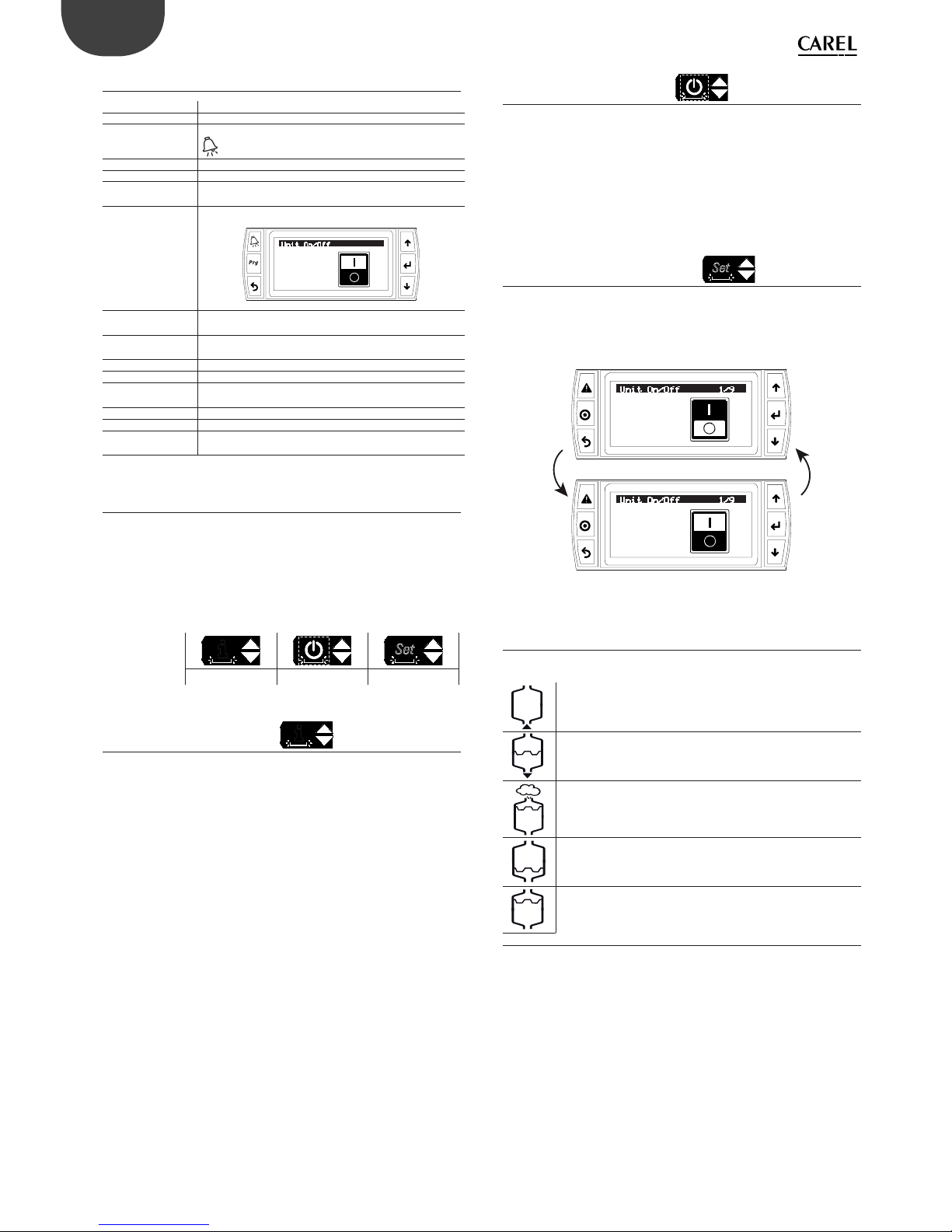
28
ENG
“heaterSteam” +0300080EN - rel. 1.0 - 27.04.2016
6.9 Display graphic area 4 - Unit status
Standby: unit in standby and ready to operate;
Production: the unit is producing steam;
Alarm: at least one alarm is active. Display the alarm by pressing
;
Off from BMS: steam production disabled from supervisor;
Off from time band: steam production disabled by time band;
Off from Din: steam production interrupted by opening the “remote ON/
OFF” contact;
Off from keypad: the unit has been switched off from the keypad
Unit On/Off
OFF
Ready for backup: the unit is ready and waiting to start operation if there is a
malfunction on the main unit.
Manual mode: test mode at fi rst start-up and to check operation (for
example: drain pump, fi ll valve…)
Warning warning notifi cations
Preheating: the unit is preheating the water in the cylinder;
Heating when
starting:
the unit, during start-up, is heating the water to reach the
production temperature;
Autotest: the unit is running the autotest;
Thermal shock: the unit is running the thermal shock procedure;
Drain: water drain due to inactivity or periodical drain, the drain
pump is active.
6.10 Display graphic area 5 - Quick access
The quick access menu is used to rapidly access unit information and
settings.
Procedure:
1. Press ESC one or more times to return to the standard display (main
screen);
2. Press UP/DOWN to display the icon corresponding to the required
quick access menu;
ICON
i
Set
Info On/Off Set point
3. Press Enter to enter the menu, UP/DOWN to navigate, ESC to exit.
6.10.8 Quick access – Info
i
Comprises read-only screens displaying the main unit information:
• Info (screen index Qc01)
Unit status
Current request
Current production
Feedwater conductivity
Water temperature (measured by NTC probe outside of the cylinder)
• Operating hour counters (screen index Qc02)
Cylinder operating hours
Unit operating hours
• Blackout (screen index Qc03)
Last pCO controller shutdown (time/date)
Shutdown duration (days, hours, minutes)
• Unit information (screen index Qc04)
Unit model
Maximum capacity, maximum power consumption, power supply,
maximum current, number of electrical phases.
• Software information (screen index Qc05)
Code
Version
OS
6.10.9 Quick access – Set
Comprises read/write screens to quickly program the unit set point:
• Main set point (screen index Qb01)
Set point setting
Control diff erential
Maximum production
• Limit probe or second probe set point (screen index Qb02)
Set point setting
Diff erential
6.10.10 Quick access – ON/OFF
Set
Unit On/Off from the keypad. Press UP/DOWN to move from one screen
to the next and switch the unit on and off . This is useful for quickly
disabling the Master controller in the event of maintenance/testing. The
screen index is Qa01.
Unit On/Off 1/9
ON
Unit On/Off 1/9
OFF
Fig. 6.e
6.11 Display graphic area 6 - Unit status icons
Graph display of unit status by icons. The status may be:
Fill (fi ll valve active)
Drain (drain pump active)
Steam production
Minimum water level in the cylinder (yellow and red LEDs on;
heaters immersed)
Water level above maximum in the cylinder (green LED on;
heaters immersed)
Tab. 6.c

29
ENG
“heaterSteam” +0300080EN - rel. 1.0 - 27.04.2016
6.12 Main menu
The parameters can be modifi ed using the keypad: press to access
and UP/DOWN to scroll the main menu.
Fig. 6.f
Main menu icons:
A. Clock
B.
Scheduler
C. Alarm thresholds
D.
Inputs/outputs
E.
Settings
Tab. 6.d
A. Clock: current time/date and time zone setting.
B. Scheduler: hourly and daily time band setting.
C. Alarm thresholds: minimum and maximum threshold setting for the main
room probe and the maximum threshold for the limit probe.
D. Inputs/outputs:
Display analogue probe readings main probe
limit probe
preheating probe (NTC)
conductivity
Digital input status remote on/off
motor protector
level sensor: low
level sensor: high
foam sensor
Analogue outputs current production
Digital output status unit on/off
contactor
drain pump
fi ll valve
SSR/fan
Foam sensor read value
foam threshold?
E. Settings: once having entered the Settings menu, login is required.
Use password 0044 to enter the Service settings.
Use password 0077 to enter the Installer settings.
Settings menu icons:
Index Icon Menu Menu type Controller type
A.
Control
Installer
Service
heaterSteam process
heaterSteam titanium
B.
Functions
Installer
Service
heaterSteam process
heaterSteam titanium
C. Confi guration
Installer heaterSteam process
heaterSteam titanium
D.
Network
Installer heaterSteam process
heaterSteam titanium
E.
Backup
Installer heaterSteam titanium
F.
Manual mode
Installer
Service
heaterSteam process
heaterSteam titanium
G.
Initialisation
Installer
Service
heaterSteam process
heaterSteam titanium
H.
Supervision
Installer heaterSteam process
heaterSteam titanium
I.
Logout
Installer
Service
heaterSteam process
heaterSteam titanium

30
ENG
“heaterSteam” +0300080EN - rel. 1.0 - 27.04.2016
6.13 Complete programming menu tree
Below is the complete tree of the confi guration menu. Remember that the screen index at the top right on the display
corresponds to the sequence of indices in each menu to reach the specifi c page (see paragraph 4.5 for further details”). There are
two types of menu: Installer and Service.
Menu Screen Menu description Menu type Controller type
A. Clock A01 Set the time, date and time zone Installer
Service
heaterSteam process
heaterSteam titanium
B. Scheduler Scheduler B01 Enable the scheduler (time bands) Installer
Service
heaterSteam process
heaterSteam titanium
B02
(visible if time bands are enabled)
Set the time bands: day, ON time, OFF time
Installer
Service
heaterSteam process
heaterSteam titanium
C. Alarm
thresholds
C01 Set the alarm thresholds
Low humidity/temperature alarm threshold
High humidity/temperature alarm threshold
Limit humidity/temperature alarm threshold
Installer
Service
heaterSteam process
heaterSteam titanium
D. Inputs/outputs Analogue inputs D01 Read values from main probe, limit probe, cylinder water tem-
perature, feedwater conductivity
Installer
Service
heaterSteam process
heaterSteam titanium
Digital inputs D02 Read status of remote On/Off , motor protector, level sensor fl oat
position, foam sensor
Installer
Service
heaterSteam process
heaterSteam titanium
Analogue outputs D03 Read current production Installer
Service
heaterSteam process
heaterSteam titanium
Digital outputs D04 Read status of unit On/Off , contactor, drain pump, fi ll valve, SSR/
fan
Installer
Service
heaterSteam process
heaterSteam titanium
In/Out Wireless probe 1 D05 Read temperature and/or humidity values
Read value of level signal and battery level on probe 1
Installer
Service
heaterSteam process
heaterSteam titanium
In/Out Wireless probe 2 D06 Read temperature and/or humidity values
Read value of level signal and battery level on probe 2
Installer
Service
heaterSteam process
heaterSteam titanium
In/Out Wireless probe 3 D07 Read temperature and/or humidity values
Read value of level signal and battery level on probe 3
Installer
Service
heaterSteam process
heaterSteam titanium
In/Out Wireless probe 4 D08 Read temperature and/or humidity values
Read value of level signal and battery level on probe 4
Installer
Service
heaterSteam process
heaterSteam titanium
E. Settings
(password)
a. Control Control type Ea01 Set the type of control Installer heaterSteam process
heaterSteam titanium
Weights Ea02 Set the weight of the two probes Installer heaterSteam process
heaterSteam titanium
Control proportional to
external signal
Ea03 Sett the hysteresis, minimum production and maximum
production
Installer heaterSteam process
heaterSteam titanium
External ON/OFF Ea04 Set the maximum production with external ON/OFF control Installer heaterSteam process
heaterSteam titanium
Modulating control Ea05 Set the set point, diff erential, min production, max production Installer heaterSteam process
heaterSteam titanium
Limit probe Ea06 Set the set point and diff erential Installer heaterSteam process
heaterSteam titanium
Cylinder op. hours Ea07 Display cylinder operating hours
Reset hour counter and set maintenance pre-alert threshold
Service heaterSteam process
heaterSteam titanium
b. Functions Autotest Eb01 Enable autotest Installer heaterSteam process
heaterSteam titanium
Enable preheat Eb02 Enable preheating
Set the water temperature to maintain Set the Off set
Installer heaterSteam process
heaterSteam titanium
Partial fi ll Eb03 Enable partial fi ll
Set partial fi ll time
Installer heaterSteam process
heaterSteam titanium
Drain due to inactivity Eb04 Enable drain due to inactivity
Set the inactivity threshold
Installer heaterSteam process
heaterSteam titanium
Periodical drain Eb05 Enable periodical drain cycles
Set the threshold for the periodical drain cycles
Installer heaterSteam process
heaterSteam titanium
Thermal shock Eb06 Enable thermal shock
Set the thermal shock threshold
Installer heaterSteam process
heaterSteam titanium
Digital output M5.2 Eb07 Enable the output relay for unit status (production) or mainte-
nance pre-alert
Installer heaterSteam process
heaterSteam titanium
Blower units Eb08 Set on and off delay for blower units Installer heaterSteam process
heaterSteam titanium
Export logs Eb09 Save the log of main variables to USB pen drive Service
Installer
heaterSteam process
heaterSteam titanium
Export alarms Eb10 Save alarm log to USB pen drive Service
Installer
heaterSteam process
heaterSteam titanium
c. Confi guration Main probe Ec01 Set the main probe: 0 to 1 V, 0 to 10 V, 2 to 10 V, 0 to 20 mA, 4 to
20 mA, NTC
Installer heaterSteam process
heaterSteam titanium
Limit probe Ec02 Set the limit probe: 0 to 1 V, 0 to 10 V, 2 to 10 V, 0 to 20 mA, 4 to
20 mA, NTC
Installer heaterSteam process
heaterSteam titanium
Wireless probes Ec03 Set the wireless probes (main/limit) Installer heaterSteam titanium
Wireless probe 1 Ec04 Set the weight of probe 1
Set the communication times
Installer heaterSteam titanium
Wireless probe 2 Ec05 Set the weight of probe 2
Set the communication times
Installer heaterSteam titanium
Wireless probe 3 Ec06 Set the weight of probe 3
Set the communication times
Installer heaterSteam titanium
Wireless probe 4 Ec07 Set the weight of probe 4
Set the communication times
Installer heaterSteam titanium
Number of evaporation
cycles before drain
Ec11 Set the number of evaporation cycles between two drain cycles Installer heaterSteam process
heaterSteam titanium
Variation in fi ll and drain
time
Ec12 Set the fi ll and drain time in relation to manufacturer default Installer heaterSteam process
heaterSteam titanium
Water hardness Ec13 Hardness value Installer heaterSteam process
heaterSteam titanium
No feedwater time Ec14 Set time to check for no water Installer heaterSteam process
heaterSteam titanium
High conductivity Ec15 Enable the high conductivity alarm
Set the alarm delay
Installer heaterSteam process
heaterSteam titanium
High conductivity Ec16 Set conductivity thresholds: warning, alarm and hysteresis Installer heaterSteam process
heaterSteam titanium
Remote ON input logic Ec22 Remote ON/OFF operating logic Installer heaterSteam process
heaterSteam titanium

31
ENG
“heaterSteam” +0300080EN - rel. 1.0 - 27.04.2016
Menu Screen Menu description Menu type Controller type
E. Settings
(password)
c. Confi guration SSR PWM period Ec23 Duration of SSR modulation period Installer heaterSteam process
heaterSteam titanium
d. Master/Slave Master/Slave Ed01 Initial Master/Slave system confi guration
Press “PRG” to confi gure the Master/Slave network
Installer heaterSteam titanium
Unit 1
Unit 2 . . . Unit 20
Ed02 Add unit to the Master/Slave system Installer heaterSteam titanium
Maximum production of
Master/Slave system.
Unit rotation.
Ed03 Set maximum production of the Master/Slave system
Set the unit rotation logic
Installer heaterSteam titanium
Advanced preheating
Rotation time.
Ed04 Enable the advanced preheating function for Master/Slave
systems
Set the rotation time between one unit and the next
Installer heaterSteam titanium
Offl ine timeout. Ed05 Set the unit offl ine time in the Master/Slave system Installer heaterSteam titanium
Disconnect unit from
Master/Slave system
Ed06 Disable/disconnect the current unit from the Master/Slave
system
Installer heaterSteam titanium
Master/Slave production Ed07 Display the request (%) and the production (kg/h / lbs/h) of the
Master/Slave system
Press “PRG” to confi gure the Master/Slave network
Installer heaterSteam titanium
Display Master/Slave
system
Ed08 Unit status with corresponding % of production
Press “PRG” to confi gure the Master/Slave network
Installer heaterSteam titanium
Display info on individual
unit. Unit 1 Unit 2 . ..
Unit 20
Ed09 Display unit operating hours, current production and any alarms
To move between the various units use the UP and DOWN
arrows
Installer heaterSteam titanium
Unit switched off for
maintenance.
Ed10 Unit switched off for maintenance Installer heaterSteam titanium
e. Backup Enable backup Ee01 Enable automatic unit backup in the event of shutdown, using a
second independent unit
Installer heaterSteam titanium
Priority when starting Ee02 Defi ne the priority of the units when in backup mode Installer heaterSteam titanium
f. Manual mode Type of manual mode Ef01 Enable manual mode: Disabled, manual management of
outputs and manual request
Service Installer heaterSteam process
heaterSteam titanium
Manual management of
outputs
Ef02 Test the outputs: fi ll valve, drain pump, contactor, SSR status, SSR
ON time, SSR OFF time
Service Installer heaterSteam process
heaterSteam titanium
Manual management of
request
Ef03 Manually set the production request Service Installer heaterSteam process
heaterSteam titanium
g. Initialisation Wizard Eg01 Start the wizard for initial unit confi guration
Set whether to display the wizard when next restarting
Service Installer heaterSteam process
heaterSteam titanium
Language Eg02 Set the language Service Installer heaterSteam process
heaterSteam titanium
Unit of measure and language when starting
Eg03 Set unit of measure (International or Imperial).
Select the language when starting
Installer heaterSteam process
heaterSteam titanium
Change password Eg04 Change the password (Service, Installer). Service Installer heaterSteam process
heaterSteam titanium
Inst. default Eg06 Unit factory reset. Important: resetting the model will cancel all
of the control settings and load the default values
Service Installer heaterSteam process
heaterSteam titanium
Software update Eg07 Update the unit software from USB pen drive Service Installer heaterSteam process
heaterSteam titanium
Export parameters Eg08 Export the confi guration parameters from the unit to USB pen
drive
Service Installer heaterSteam process
heaterSteam titanium
Import parameters Eg09 Import the confi guration parameters from USB pen drive to
the unit
Service Installer heaterSteam process
heaterSteam titanium
h. Supervision Unit supervision address
on BMS port
Eh01 Set the unit address for supervision. Enable the supervisor type
and protocol
Installer heaterSteam process
heaterSteam titanium
BMS port communication
settings
Eh02 Set the communication parameters for supervision via BMS:
Baud rate, stop bits and parity
Installer heaterSteam process
heaterSteam titanium
BACnet MS/TP
confi guration
Eh03 Set the address, maximum number of masters and maximum
number of frames
Installer heaterSteam process
heaterSteam titanium
Ethernet network settings Eh04 Set DHCP, IP address, mask, gateway, DNS for the Ethernet
network. Important: these values must be provided by the local
network administrator
Installer heaterSteam process
heaterSteam titanium
Supervision settings on
Ethernet port
Eh05 Select the protocol on the Ethernet port: ModBus or BACnet Installer heaterSteam process
heaterSteam titanium
i. Logout Logout Ei01 Information on the type of login performed. Possibility to logout Service Installer heaterSteam process
heaterSteam titanium
Tab. 6.e
6.14 Alarms
Any active alarms will be shown on the corresponding screen with direct
access from the display.
When an alarm occurs, the corresponding alarm button
starts fl ashing.
In these conditions, pressing the alarm button
once displays the type
of alarm. In the event of potentially dangerous alarms, the humidifi er
automatically stops steam production. For certain alarm events, as well as
the alarm signal, the alarm relay is activated (see Chap. 13 “Alarm table”).
When the cause of the alarm is no longer present:
• the humidifi er and the alarm relay are reset automatically or manually;
• the message shown on the display can only be cleared manually (see
Chap. 13 “Alarm table”);
Even if no longer active, the alarm status continues to be indicated until
“clear display” button is pressed.
Alarms that are still active cannot be reset. If there is more than one alarm,
the display shows all the alarms in sequence.
From the alarm screen, the alarm log can be displayed by pressing “Enter”
. For the complete table of alarms, see chapter 13. Alarm table.

32
ENG
“heaterSteam” +0300080EN - rel. 1.0 - 27.04.2016
7. USER MENU AND UNIT CONFIGURATION
The following paragraphs describe the heaterSteam programming
menu. Remember that the screen index at the top right on the display
corresponds to the sequence of indices in each menu to reach the
specifi c page (see paragraph 4.4 for further details).
7.1 Main menu
7.1.1 Menu A. Clock (Main menu)
The Clock menu is used to set the time, date and time zone. Setting the
time zone will automatically update standard/daylight saving time.
Screen index Description Parameter
A01
Clock Set the date, time and time zone.
7.1.2 Menu B. Scheduler (Main menu)
The Scheduler menu is used to enable the time bands.
Index Description Parameter
B01
Scheduler Enable time bands
Default: time bands disabled
To confi gure the humidifi er operating time bands for a specifi c day (24h),
use screen B02 (visible only if the scheduler is enabled). A time band can
be set with production disabled (OFF), enabled (ON), or enabled with s
specifi c set point (ON+SET). Setting the ON time band, the unit uses the
main set point confi gured on screen Qb01. If setting ON+SET, the specifi c
set point for the time band can be confi gured.
Index Description Parameter
B02
Scheduler Defi ne daily and weekly time bands
Fig. 7.a
In the example shown here in Fig.7.a, the time band from 8.00 to 9.00
is enabled for production with a specifi c set point of 50%rH. After 9.00,
humidifi er production will not be enabled.
unit of measure indication: symbol displayed unit of measure
% %rH
°C degrees Celsius
°F degrees Fahrenheit
Once the time bands have been defi ned for one day, press to copy
the currently displayed bands (daily) to the next day. When the time
bands have been set, the display shows the
symbol.
Note: if control is by external signal, the humidifi er can only be
switched ON or OFF.
7.1.3 Alarm thresholds (Main menu)
To check that the relative humidity measured by the probe transducer is
within certain predefi ned values, two alarm thresholds can be confi gured:
• high relative humidity alarm threshold, for both the main probe and
limit probe;
• low relative humidity alarm threshold for the main probe.
On exceeding these thresholds, an alarm is activated and the
corresponding relay contact on the main control board is closed.
Temperature thresholds can also be set.
Index Description Parameter
C01
Alarm
thresholds
Set alarm thresholds
Low humidity/temperature alarm threshold
High humidity/temperature alarm threshold
Limit humidity/temperature alarm threshold
Defaults:
low humidity/temperature: 0% rH / 0°C(32°F);
high humidity/temperature: 100% rH / 100 °C(°F);
humidity/temperature limit: 100% rH / 100 °C(°F);
Possible settings: 0-100
7.1.4 Inputs/outputs (Main menu)
The Inputs/outputs menu is used to read the status of the inputs and
outputs and check unit operation and status.
Index Description Parameter
D01
Analogue inputs Read values from main probe, limit probe, cylinder
water temperature, feedwater conductivity
D02
Digital inputs Read status of remote On/Off , motor protector, level
sensor fl oat position, foam sensor
D03
Analogue outputs Read current production
D04
Digital outputs Read status of unit On/Off , contactor, drain pump, fi ll
valve, SSR/fan
D05
In/Out Wireless
probe 1
Read temperature and/or humidity values
Read value of level signal and battery level on probe 1
D06
In/Out Wireless
probe 2
Read temperature and/or humidity values
Read value of level signal and battery level on probe 2
D07
In/Out Wireless
probe 3
Read temperature and/or humidity values
Read value of level signal and battery level on probe 3
D08
In/Out Wireless
probe 4
Read temperature and/or humidity values
Read value of level signal and battery level on probe 4
Description of level sensor fl oat position:
Float Low level sensor High level sensor LED indication
High ON ON green
Middle ON OFF yellow
Low OFF OFF red
7.2 Menu E. Settings - a. Control
Login is required to access the settings menus:
• service menu: password 0044;
• installer menu: password 0077.

33
ENG
“heaterSteam” +0300080EN - rel. 1.0 - 27.04.2016
7.2.1 Control type (Installer menu)
To set the type of control, use the following screen:
Index Description Parameter
Ea01
Control type Set the type of control
Default: humidity (one probe)
Possible settings:
proportional to external signal, proportional to external signal with limit probe, On/Off signal, humidity
(one probe), temperature (one probe), humidity with
limit, temperature with limit, humidity (two probes),
temperature (two probes)
The possible settings are:
• proportional to external signal: proportional control with signal from
an external controller;
• proportional to external signal with limit probe: proportional
control with signal from an external controller plus limit probe;
• On/Off signal: humidity control with humidistat;
• humidity (one probe): humidity control with main probe;
• temperature (one probe): temperature control with main probe;
• humidity with limit: humidity control with main probe and limit
probe;
• temperature with limit: temperature control with main probe and
limit probe;
• humidity (two probes): humidity control with two probes, the
controller calculates the weighted average of the two values read;
• temperature (two probes): temperature control with two probes, the
controller calculates the weighted average of the two values read.
For “humidity (one probe)” or “temperature (one probe)” control, one
single main probe can be connected and confi gured, either wired or
wireless.
For “humidity with limit” or “temperature with limit” control, a wired
probe can be connected as the main probe and a wired probe as the
limit. If using wireless probes (maximum of four), two groups of probes
can be defi ned: the group of main probes and the group of limit probes.
In this case, the average will be calculated between the main probes,
depending on the defi ned weight, and the limit probes will also have
their own average, again depending on the defi ned weight.
For “humidity (two probes)“ or “temperature (two probes)” control, only a
group of main probes can be defi ned. Wired probes can be connected to
the main probe input (M2.1) and the limit probe input (M2.5), which will
be used as a second probe, with the average calculated. If using wireless
probes (maximum of four), only a group of main probes can be defi ned,
with the average calculated, depending on the defi ned weight.
For the connections of the signals and/or probes, see chap. 4.
7.2.2 Weighted average of the probes (Installer menu)
If using two temperature probes or two humidity probes, the humidifi er
controller will calculate the weighted average of the probe readings.
In this way, two probes can be used, for example humidity probes, at
opposite ends of the room, calculating the average.
Index Description Parameter
Ea02
Weight of the
probes
Set the weight of the probes
Default: 100
Possible settings: 0-100
Step: 1
The weight of each probe should be expressed with a value from 0 to
100.
The weighted average is calculated as follows:
Weighted average = ((S1×p1)+(S2×p2))
--------------------------- (p1+p2)
where “Sx” is the probe reading, and “px” the relative weight.
To calculate the arithmetic average, equal weights should be set (for
example: p1 = p2 = 100).
If using wireless probes, the weights of each device can also be defi ned;
in this case a maximum of four wireless probes can be connected, and
consequently the formula shown previously for calculating the weighted
average is extended to four devices.
7.2.3 Proportional control con guration
If using control proportional to external signal or control proportional to
external signal with limit probe, the hysteresis, minimum and maximum
production need to be set.
Index Description Parameter
Ea03
Control
proportional to
external signal
Set the hysteresis, min production and max
production
Defaults:
Hysteresis = 2%
Minimum production = 4%
Maximum production = 100%
Possible settings:
Hysteresis = 0-100%
Minimum production = 0-10%
Maximum production = 0-100%
7.2.4 Control from external ON/OFF signal
con guration
If using control with On/Off signal, the maximum production needs to
be set.
Index Description Parameter
Ea04
External ON/OFF Set maximum production with external ON/OFF
control
Default: 100%
Possible settings: 0-100%
7.2.5 Modulation con guration (Installer menu)
If using modulating control, the related parameters need to be set:
Index Description Parameter
Ea05
Mod. control Set point, diff erential, min production, max produc-
tion
Defaults:
Set point = 50%rH (42°C) (107.6°F)
Diff erential = 5%rH (5°C) (9°F)
Minimum production = 4%
Maximum production = 100%
Possible settings: 0-100
7.2.6 Limit probe con guration (Installer menu)
A second probe can be connected as a limit probe at the outlet. This
probe has the purpose of preventing the relative humidity downstream
of the steam distributor from exceeding a set value, confi gured by the
user. As this probe has a modulating action, the diff erential can also be
set. The limit probe, within its range of activation, has priority over the
main probe (as the limit probe set point is higher than the main probe
set point).
Index Description Parameter
Ea06
Limit probe Limit probe set point and diff erential
Defaults:
Set point = 100%rH
Diff erential = 5%
Possible settings: 0-100

34
ENG
“heaterSteam” +0300080EN - rel. 1.0 - 27.04.2016
7.2.7 Cylinder operating hours (Service menu)
The “Cylinder op. hours” screen displays the eff ective number of cylinder
working hours.
Index Description Parameter
Ea07
Cylinder op.
hours
Display cylinder operating hours, reset hour counter
and set maintenance pre-alert threshold
Default: Pre-alert = 48 hours
Possible settings: 0-999
If the cylinder needs to be replaced, the hour counter must be reset using
the “Reset” parameter; the hour counter will then start again from zero.
The “Pre-alert” item sets the maintenance pre-alert, which is activated “x”
hours before the maintenance alarm, and where “x” is the value set for the
“Pre-alert” parameter. This allows time to plan the maintenance operation.
The “maintenance alarm” time is the number of cylinder operating hours
before it needs to be cleaned. During the start-up wizard, the feedwater
hardness is entered, and the ”maintenance alarm” depends on this value,
as shown in the table below:
Water hardness Maintenance alarm
0-10°f STOP for cleaning/maintenance 3000 hours
10-20°f STOP for cleaning/maintenance 1500 hours
20-30°f STOP for cleaning/maintenance 1000 hours
30-40°f STOP for cleaning/maintenance 800 hours
If during the wizard the value is set to “automatic”, rather than entering
the hardness value, the maintenance alarm is automatically associated
to the feedwater conductivity read by the conductivity meter. The
following table shows the dependency of the maintenance alarm on
water conductivity:
Water conductivity Maintenance alarm
1 - 50 μS/cm Warning at 3000 hours without STOP for cleaning
maintenance (it is assumed that the water comes from a
reverse osmosis system)
50 - 100 μS/cm STOP for cleaning/maintenance 3000 hours
> 100 μS STOP for cleaning/maintenance 1500 hours
The conductivity is read periodically, and the maintenance alarm times is
thus updated as a consequence.
Therefore, for example, if the water hardness is set to 15°f, the
“maintenance alarm” time will be 1500 eff ective cylinder operating
hours; if the “maintenance pre-alert” time is set to 48 hours (default), the
maintenance pre-alert will be signalled after 1452 hours.
7.2.8 Unit operating hours (Service menu)
To display information on unit operating hours, access the “Unit operating
hours” menu.
Index Description Parameter
Ea08
Unit operating
hours
Display unit operating hours
7.3 Menu E. Settings - b. Functions
7.3.1 Autotest (Installer menu)
To enable the autotest procedure when the unit is next started, access
the corresponding menu item.
Index Description Parameter
Eb01
En. Autotest Enable the autotest procedure.
Default: Enabled
This procedure checks operation of the level sensor; for further details see
chapter 6. “Start-up and user interface”.
7.3.2 Preheat cylinder water (Installer menu)
To ensure production starts quickly, the preheat function can be enabled.
In this way, even when there is no steam request, the water temperature
in the cylinder is kept at a value specifi ed by the user. When production
is next needed, the water is thus warmer than ambient temperature and
consequently production will start faster.
Index Description Parameter
Eb02
Preheating Enable preheat
Set the water temperature to maintain
Set water temperature off set
Defaults:
Preheat disabled
Water temp. set point in the cylinder = 80°C (176°F)
Off set = 3%rH (3°C / 5.4 °F)
Set point range: 50-80°C (122-194°F)
Off set range: 2-20%rH (0-20°C / 32-68°F)
The water temperature in the cylinder is read by the passive NTC
temperature probe in contact with the cylinder. The operating principle
of the preheat function is described in the following graphs, the fi rst for
control with probes, the second for control by external signal.
Preheat with autonomous modulating control with probes
The preheating function, if active, overlaps the control diagram and
modulates the power delivered to the heaters in relation to the water
temperature and the preheating set point. The operating principle of the
preheat function is described in the following graph:
P
OFF
ON
%rH
hy
max
Steam_Pr
P
min
BP
Oset
OFF
OFF
ON
hy
%rH
St
Vapore
Pre-riscaldo
Fig. 7.b
Key
Steam_pr Steam production %rH Humidity measurement
P
max
Max production hy Activation hysteresis
P
min
Min production BP Proportional band
St Set point

35
ENG
“heaterSteam” +0300080EN - rel. 1.0 - 27.04.2016
Preheat with control by external signal
The preheating function, if active, shifts the control diagram by a value
equal to the “off set”. The preheat function modulates the power delivered
to the heaters in relation to the water temperature and the preheating
set point.
P
OFF
ON
100%
hy
max
Steam_Pr
P
min
Oset
OFF
OFF
ON
hy
%rH
Y
0%
2 x hy
Vapore
Pre-riscaldo
Fig. 7.c
Key
Steam_pr Steam production y External signal
P
max
Max production hy Activation hysteresis
P
min
Min production
7.3.3 Fill cycles in PWM mode after drain to dilute
cycles and high level/foam (Installer menu)
After a drain to dilute cycle or high level/foam, the fi ll valve is opened
to replenish water up to the maximum level of the fl oat. The addition of
fresh water aff ects steam production, as it decreases the average water
temperature inside the cylinder: to reduce the negative impact of fresh
water on steam production, the user can activate PWM mode for the fi ll
cycles after drain to dilute cycles and high level/foam.
PWM mode for fi ll cycles works as follows:
1. the mass of fresh water needed to replenish the water level is divided
into smaller amounts of fresh water;
2. by keeping the partial fi ll cycles as far apart as possible, each small
amount of fresh water has more time to heat up before more fresh
water is fi lled, thus reducing the negative impact of the fresh water
on steam production.
The duration of each fi ll cycle can be defi ned in seconds:
Index Description Parameter
Eb03
Partial fi ll Enable partial fi ll.
Set the partial fi ll cycle time.
Defaults:
partial fi ll: enabled
fi ll time: 5 seconds
Possible settings 1-199 seconds
7.3.4 Total drain due to inactivity (Installer menu)
For reasons of hygiene, it is recommended to empty the cylinder so as
to prevent water from stagnating inside when there is no humidifi cation
request for an extended period. The user can set the automatic total drain
due to inactivity time in hours:
Index Description Parameter
Eb04
Drain due to
inactivity
Enable drain due to inactivity;
set the hours of inactivity without production request that
must expire before draining
Defaults:
drain due to inactivity: enabled;
hour threshold: 72 hours
Possible settings: 1-999 hours
Remarks: heaterSteam must remain on in order to empty
the cylinder. The display shows “DRAIN TO DILUTE” during
the drain due to inactivity cycle.
Automatic total drain due to inactivity cycle is enabled by default and
the maximum inactivity time is three days (72 hours): the cylinder will be
automatically emptied when heaterSteam remains on for at least three
days without humidifi cation request.
7.3.5 Periodical drain (Installer menu)
If the feedwater is turbid or has a high mineral content, the cylinder can
be periodically drained in order to clean and dilute the water as much as
possible. For this operation to be eff ective, it is recommended to carry it
out at least once every two-three days. The user can set the automatic
periodical total drain cycle as follows:
Index Description Parameter
Eb05
Periodical
drain
Enable periodical drain;
Set the time between one periodical drain cycle and
the next (in hours);
Defaults:
periodical drain: disabled;
hour threshold: 10 hours
Possible settings: 0-999 hours
Remarks: heaterSteam must remain on in order to empty the cylinder. The display shows “PERIODICAL DRAIN”
during the periodical drain cycle.
Periodical drain is disabled by default. The periodical drain hour counter
considers the eff ective production time.
7.3.6 Thermal shock to assist detachment of scale
(Installer menu)
Considering the natural trend of scale to build up on the inside surfaces of
the cylinder, the materials used are all as smooth as possible. To limit scale
build up even more, especially on the heaters, the thermal shock function
has been implemented. This function completely empties the cylinder
when production stops (and consequently when the water is still boiling).
At the end of the drain cycle, water is refi lled until reaching the top level.
The thermal shock function is set to be activated a certain number of hours
of eff ective production time between two consecutive cycles. On reaching
the time threshold, the thermal shock function will be activated the next
time production stops, without limits in terms of waiting time.
Note: in the event of non-stop operation 24 hours a day, the thermal
shock function will never be activated and will remain constantly
pending.
Index Description Parameter
Eb06
Thermal
shock
Enable thermal shock;
Set the time between one thermal shock cycle and the
next (in hours);
Defaults:
thermal shock: disabled;
interval: 250 hours
Possible settings: 0-1000 hours
Remarks: the notifi cation center will signal when thermal
shock is pending if the time threshold has been exceeded
by production is still in progress. During the function,
the display will show “Thermal shock” in the unit status
graphic area. A notifi cation message will be shown when
there are six hours of production left until thermal shock
is activated; the pending thermal shock can be cancelled
on this screen.

36
ENG
“heaterSteam” +0300080EN - rel. 1.0 - 27.04.2016
7.3.7 Unit status signal or maintenance pre-alert
(Installer menu)
The humidifi er controller is fi tted with a relay contact for remotely
signalling unit status (production) or a maintenance pre-alert. Terminals
M5.1 and M5.2 are used for these functions.
Index Description Parameter
Eb07
Digital output
M5.2
Enable output relay for unit status (production) or
maintenance pre-alert.
Default: Unit status (production);
For further information on relay see paragraph 4.9 Unit status/
maintenance pre-alert contact
7.3.8 Blower unit con guration (Installer menu)
To best manage the blower units in applications where steam is delivered
directly into the room, the blower on and off times can be set. Delaying
activation of the blower unit allows the system to reach the operating
temperature before the fan is activated. Delaying deactivation of
the blower unit guarantees that parts in contact with the steam will
be completely dried, meaning that when next starting, there is no
condensate in the steam distribution line, avoiding droplets being blown
into the room.
Index Description Parameter
Eb08
Blower units Set the delay time (seconds) for activation and deactiva-
tion of blower units
Defaults: start delay: 0 seconds;
stop delay: depending on the size (30 seconds for
UR002-UR013; 60 seconds for UR020-UR040; 90 seconds
for UR053-UR080)
Possible settings: 0-600 seconds
7.3.9 Save logs (Service and Installer menu)
The log of the main variables can be saved to USB pen drive. The following
variables are logged:
• Unit On/Off
• Unit status
• Active alarms
• Request (%)
• Production (kg/h)
• Level sensor status
• Fill
• Drain
The fi le is saved in .csv format. The logs are constantly saved to internal
memory, and are thus exported to the memory key in the USB Host port
by entering menu screen Eb09. Set “Export to USB” to “YES”. Progress of
the operation will be shown under “progress”.
Index Description Parameter
Eb09
Export logs Save the log of main variables to USB pen drive
Export to USB = Yes, to save the log
USB key
Fig. 7.d
7.3.10 Save alarm log
The alarm log can be saved to USB pen drive. To export the file, plug the
USB pen drive into the c.pHC and go to screen Eb10, then set “YES” for
the “Export?” parameter.
Index Description Parameter
Eb10
Export alarms Save alarm log to USB pen drive
Default: No
The fi le will be saved in the pen drive’s root directory and will be called
“AlrmLog.txt”.
7.4 Menu E. Settings - c. Confi guration
7.4.1 Main probe (Installer menu)
The main probe can be confi gured on the screen with index Ec01.
Index Description Parameter
Ec01
Main probe Main probe confi guration;
Defaults:
Enable: Enabled (depending on the type of control)
Type: 0-10V
Minimum: 0% r.H.
Maximum: 100% r.H.
Off set: 0
En. Al (enable alarms): YES
Delay: 120 seconds
Possible settings:
Type: 0-10V/0-1V/NTC/4-20mA/0-20mA/2-10V
Minimum: 0-100%r.H .
Maximum: 0-100%r.H.
Off set: 0
En. Al (enable alarms): YES
Delay: 0-999 seconds
For each probe, after having specifi ed the type, the minimum and
maximum values readable by the probe can be defi ned, as well as an
“off set” to compensate for any imprecisions in the value read (example:
off set = 3 %r.H. corresponds to 3 percent increase of the humidity value
read by the probe). Parameter “En. Al.” activates the alarms corresponding
to any probe faults. If a malfunction is detected for a time greater than
the value of “Delay” (seconds), the “main probe broken or disconnected”
alarm is activated.
7.4.2 Limit probe (or second probe - Installer menu)
The limit probe (if present) can be confi gured on the screen with index
Ec02.
Index Description Parameter
Ec02
Limit probe Limit probe confi guration;
Default:
Enable: Enabled (depending on the type of control)
Type: 0-10V
Minimum: 0% r.H.
Maximum: 100% r.H.
Off set: 0
En. Al (enable alarms): YES
Delay: 120 seconds
Possible settings:
Type: 0-10V/0-1V/NTC/4-20mA/0-20mA/2-10V
Minimum: 0-100%r.H.
Maximum: 0-100%r.H.
Off set: 0
En. Al (enable alarms): YES
Delay: 120 seconds
For each probe, after having specifi ed the type, the minimum and maximum values readable by the probe can be defi ned, as well as an “off set”
to compensate for any imprecisions in the value read (example: off set
= 3 %r.H. corresponds to 3 percent increase of the humidity value read
by the probe). Parameter “En. Al.” activates the alarms corresponding to
any probe faults. If a malfunction is detected for a time greater than the
value of “Delay” (seconds), the “limit probe broken or disconnected” alarm
is activated.

37
ENG
“heaterSteam” +0300080EN - rel. 1.0 - 27.04.2016
7.4.3 Wireless probes (Installer menu)
Confi guration of the wireless probes involves defi ning the weight of each
probe; for further details on the averages see paragraph 7.2.2 “Weighted
average of the probes”.
Screen Ec03 can be used to deactivate, activate as main probe or limit
probe each of the four possible wireless probes.
Index Description Parameter
Ec03
Wireless probes Wireless probe confi guration (main and limit)
Defaults:
Probe 1: disabled
Probe 2: disabled
Probe 3: disabled
Probe 4: disabled
Possible settings: disabled, main probe, limit probe
To confi gure the wireless probes, weights and communication times,
use screens Ec04, Ec05, Ec06 and Ec07, depending on the number of
probes connected.
Index Description Parameter
Ec04
Ec05
Ec06
Ec07
Wireless probe 1
Wireless probe 2
Wireless probe 3
Wireless probe 4
Confi gure probe weight and communication times;
Defaults:
Weight: 100
Transmission time: 10s
Disconnection delay: ms
Possible settings:
Weight: 0 to 100
Transmission time: 5-3600 seconds
Disconnection delay: ms
7.4.4 Maximum number of evaporation cycles
between drain to dilute cycles settable by the
user (Installer menu)
The number of evaporation cycles between two successive drain to dilute
cycles is calculated internally, based on feedwater conductivity. To use
the automatic calculation, set “Evaporation cycles before drain” = “Auto”.
The “Evaporation cycles before drain” parameter sets the maximum
number of evaporation cycles allowed between two drain to dilute
cycles.
The number of evaporation cycles used by the controller will be the
lower of the value set manually by the user and calculated automatically.
Index Description Parameter
Ec11
Evaporation
cycles before
drain
Set the number of evaporation cycles between two drain
to dilute cycles.
Default: number of cycles: Auto;
Possible settings: Auto (automatic management according to feedwater conductivity); 1 to 40
Remarks: if the parameter = “Auto”, the number of evaporation cycles between two drain to dilute cycles is
set automatically by the controller based on feedwater
conductivity.
7.4.5 Duration of the ll and drain to dilute cycles
settable by the user (Installer menu)
On screen Ec12, the duration of the fi ll time after the evaporation cycle
and the duration of the drain to dilute cycle can be set in relation to the
default parameter values.
Index Description Parameter
Ec12
Variation in
fi ll and drain
times
Set the fi ll after evaporation and drain to dilute times in
relation to the default values
Defaults:
variation in fi ll time: 100%
variation in drain time: 100%:
Possible settings:
variation in fi ll time: 20-100%
variation in drain time: 0-190%
The duration of the drain to dilute cycle is set using the “variation in drain
time” parameter, which defi nes the time as a% of the default value:
new drain time = (default drain time × variation in drain time)/100
Example: if the default time is 10 s and “variation in drain time” = 50%,
then the new time will be = 10 s x 50/100 = 5 s.
The same also applies to the fi ll time after the evaporation cycle, in this
case using the “variation in fi ll time” parameter:
new fi ll time = (default fi ll time × variation in fi ll time)/100
Remarks on the duration of the drain to dilute cycle: if the drain to dilute
time is very short, there may be the RISK OF FOAM/CORROSION due to
increased internal conductivity.
Low values should be set for the “variation in drain time” parameter only
after having carefully evaluated the water quality and the consequences.
Warning: RISK OF FOAM FORMING WHEN “variation in drain time”
IS TOO LOW FOR THE WATER QUALITY.
“variation in drain time” = 100 % means that the default value will be used.
“variation in drain time”< 100 % means that the drain time will be less
than the default, consequently introducing less fresh water when next
refi lling, reducing the negative impact on steam production (important
in high-precision applications).
Setting the “variation in drain time” for precise %RH control:
the “variation in drain time” must be set as low as possible, without
however causing formation of foam/corrosion. Proceed by trial and error
so as to fi nd the most suitable value.
Remarks on the duration of the water fi ll cycle: this can be used to off set
water pressure upstream of the humidifi er. Decrease the fi ll time in the case
of high pressure and vice-versa. Nonetheless, feedwater pressure must be
within the range of pressure values specifi ed in Tab 16.b (1-8 bars)
7.4.6 Set feedwater hardness (Installer menu)
The user can set the feedwater hardness. Carel provides an analysis kit
(P/N: KITTH00000) to read feedwater hardness.
The “Water hardness” parameter defi nes the maintenance alarm for
cleaning the cylinder and the heaters.
Index Description Parameter
Ec13
Water
hardness
Set the feedwater hardness
Possible settings:
Hardness: Auto, Manual
Manual setting: 0-10°f, 10-20°f, 20-30°f, 30-40°f
Remarks: if the value is set to Auto, the water
hardness is estimated by the controller based on the
conductivity value.
If water hardness is not set, the controller independently manages
the type of water based on the conductivity reading. Although there
is no reliable relationship between water hardness and conductivity, a
hardness of 40°f is typically equivalent to a conductivity of approximately
900-1000 μS/cm at 20°C.
See paragraph 7.2.7 Cylinder operating hours for information on the
maintenance alarm times in relation to water hardness or conductivity.
7.4.7 No feedwater setting (Installer menu)
In the event of no feedwater, the corresponding “No water” alarm is
displayed. After the alarm has been displayed and the “no feedwater time”
has elapsed, the controller attempts a new fi ll cycle. At each attempt, the
“no feedwater time” is multiplied by the number of times it has already
been carried out. The controller therefore performs a series of attempts to
refi ll with water, for a maximum time of fi ve hours after the alarm occurs.
The alarm is reset only if the water level eff ectively reaches the
intermediate position (yellow LED).
Index Description Parameter
Ec14
No feedwater
time
Set the time to check for no feedwater.
Default: 10 minutes
Possible settings: 0 to 20 minutes
Step: 1 minute
Remarks: if the value is set to 0, no more attempts will
be made to refi ll the water and the alarm will not be
reset

38
ENG
“heaterSteam” +0300080EN - rel. 1.0 - 27.04.2016
7.4.8 Enable and set high conductivity alarm (Installer
menu)
The controller allows conductivity thresholds to be set for the activation
of alarms when the limits are exceeded. In other words, excessive
conductivity and consequently high concentration of salts in the
feedwater can be signalled. These alarm thresholds are programmable
using the following control parameters:
Index Description Parameter
Ec15
High
conductivity
Enable the high conductivity alarm and set the alarm
delay.
Defaults:
enabled: YES
alarm delay: 60 seconds
Possible settings:
enabled: YES/NO;
alarm delay: 0-300 seconds
Remarks: once the threshold has been exceeded (if the
alarm is enabled), the controller waits for the “alarm
delay” to elapse before displaying the alarm. If during
this waiting time the conductivity falls back below the
threshold, the alarm is not activated. This helps avoid false alarms due to variations in the conductivity reading.
7.4.9 Set high conductivity alarm thresholds
(Installer menu)
Two high conductivity thresholds can be set. If exceeding the fi rst (lower)
threshold, a warning is shown without stopping operation, while if
exceeding the higher threshold, an alarm is activated and the unit shuts
down as a precaution.
Index Description Parameter
Ec16
High
conductivity
Set the high conductivity thresholds.
Default:
pre-alert: 1250 μS/cm
alarm: 1500 μS/cm
Hysteresis: 25 μS/cm
Possible settings:
pre-alert: 0-1500 μS/cm
alarm: 0-1500 μS/cm
Hysteresis: 0-100 μS/cm
Remarks: the hysteresis is used to reset the alarm
if the conductivity falls below the threshold by the
value set for the “Hysteresis”.
7.4.10 Remote ON/OFF operating logic (Installer menu)
Screen Ec22 is used to set the operating logic of the remote ON/OFF
contact (normally open or normally closed).
Index Description Parameter
Ec22
Remote ON
input logic
Set the operating logic of the remote on/off input
Default: Remote ON input logic = N.O
Possible settings: Remote ON input logic: N.O., N.C.
7.4.11 Set the PWM period for the SSR (Installer menu)
Menu Ec23 can be used to change the modulation period of the SSR. The
default value of the parameter is 8 seconds. Decreasing this value adjusts
the precision on the relative humidity set point.
Index Description Parameter
Ec23
SSR PWM
period
Set the SSR modulation period
Default: SSR PWM period = 8 seconds
Possible settings: SSR PWM period: 1-199 seconds
7.5 E.Settings – d.Master/Slave
7.5.1 Master/Slave system network settings (Installer
menu)
To increase total production capacity when one single unit is not
suffi cient, the Master/Slave function can be used to connect up to 20
units together in just one system. To set and enable the individual units
in the system, go to the “Network” menu, specifi cally starting from screen
Ed01.
Initial Master/Slave system confi guration:
Index Description Parameter
Ed01
Master/Slave Initial Master/Slave system confi guration
Press “PRG” to confi gure the Master/Slave network
Index Description Parameter
Ed02
Unit 1
Unit 2
-
Unit 20
Add unit to the Master/Slave system
To add a unit to the network enter the unit’s IP address.
Scroll between the units using the UP/DOWN buttons
Master/Slave system function confi guration: from screen Ed07 (Master/
Slave production) press “PRG” for the following confi gurations:
Index Description Parameter
Ed02
Unit 1
Unit 2
-
Unit 20
Add unit to the Master/Slave system.
To add a unit to the network enter the unit’s IP address.
Scroll between the units using the UP/DOWN buttons
.
Ed03
Maximum
production of
Master/Slave
system
Unit rotation
Set the maximum Master/Slave system production.
Load: this is the maximum capacity eff ectively required
for the Master/Slave system, settable by the user.
Maximum: this is the sum of the maximum capacities of
the units added to the Master/Slave system
Set the unit rotation logic.
Rotation: Grouped (Default), Balanced
Ed04
Advanced
preheating
Rotation time
Enable the advanced preheating function for Master/
Slave systems.
Possible settings: YES/NO
Set the auto-rotation time between units
Settings: 0 to 65535 hours (Default 3 hours).
If auto-rotation time = 0 the function is disabled
Ed05
Offl ine timeout. Set the offl ine time for the units in the Master/Slave
system
Possible settings: 500-10000 ms
Ed06
Disconnect unit
from Master/
Slave system
Disconnect the current unit from the Master/Slave
system
Possible settings: YES/NO
Remarks: this disconnects and removes the current unit
from the Master/Slave system.
Display Master/Slave system production:
Index Description Parameter
Ed07
Master/Slave
production
Display the request (%) and the production (kg/h /
lbs/h) of the Master/Slave system
Display unit status and the percentage of production for each unit in the
Master/Slave system:
Index Description Parameter
Ed08
Display Master/Slave
system
Unit status with corresponding % of production
Ed09
Display info on
individual unit.
Display unit operating hours, current production
and any alarms.
To scroll between the various units use the UP and
DOWN arrows
The display is available for each unit
Maintenance on the units in the Master/Slave system:
Index Description Parameter
Ed10
Unit switched off for
maintenance.
Unit switched off for maintenance
For detailed information on the Master/Slave system, see chapter 8
“Master/Slave system”.

39
ENG
“heaterSteam” +0300080EN - rel. 1.0 - 27.04.2016
7.6 E.Settings – e.Backup
7.6.2 Enable backup unit (Installer menu)
In some critical applications where relative humidity control is very
important, it may be essential have a backup unit available in the event
of malfunctions on the main unit. To enable the backup unit, go to screen
Ee01:
Index Description Parameter
Ee01
Enable backup Enable automatic unit backup in the event of shutdown,
using a second independent unit.
Default: Disabled
Possible settings: Enabled/Disabled
After having enabled the backup function, the unit priority can be
defi ned so as set the unit that will start fi rst in the event of simultaneous
activation:
Index Description Parameter
Ee02
Priority when
starting
Defi nition of backup unit priority
Default: Disabled
Possible settings: Enabled/Disabled
The priority must be set to “YES” only on one of the two units; the “priority”
parameter on the second unit must be set to “NO”.
7.7 E.Settings – f.Manual mode
7.7.1 Manual mode (Service and Installer menu)
During fi rst start-up or maintenance, “manual mode” may be useful in
order to check the operation of the main devices on the heaterSteam
humidifi er. All the operations carried out in this menu have actual eff ect
on the unit, i.e. eff ectively activate/deactivate or modify the status of the
components. Manual mode is only available when the unit is OFF and
without any active alarms. In addition, to safeguard the unit, the heaters
can only be activated when there is water in the cylinder (high level,
corresponding to green LED on)
Important: manual mode should only be activated by qualifi ed
personnel; improper use may cause serious damage to the unit.
Index Description Parameter
Ef01
Manual
mode
Enable “Manual mode” to check operation of the individual
components.
Default: Disabled
Possible settings: Disabled, manual outputs, manual production
Remarks: when exiting “Manual mode”, the settings are restored and normal operation resumes automatically. If the user
does not set any parameters in the “Manual mode” menu for 30
minutes, manual mode is automatically disabled.
Index Description Parameter
Ef02
Manual management
of outputs
Enable “Manual mode” to check operation of the individual
components..
Test fi ll valve
Test drain pump
Open/close the contactor
SSR status (depending on the water level in the cylinder)
SSR ON time (depending on the water level in the cylinder)
SSR OFF time (depending on the water level in the cylinder)
Index Description Parameter
Ef03
Manual
management
of production
request
Manual production settings.
7.8 E.Settings – g.Initialisation
7.8.1 Initial wizard (Service and Installer menu)
The Wizard menu, screen index Eg01, is used to initiate step-by-step
programming of the parameters required for installation. Below are the steps
included in the fi rst start-up procedure (some steps may not be displayed, if
not necessary):
1/9 - select the model (only if the replacement controller is not confi gured);
2/9 - water hardness: auto or user-defi ned;
3/9 - manual water hardness setting;
4/9 - type of control;
5/9 - select the main room probe type;
6/9 - select the limit probe type;
7/9 - set the limits for the active probes;
8/9 - set the drain to dilute cycles: auto or user-defi ned;
9/9 - manual drain to dilute cycle setting.
Index Description Parameter
Eg01
Wizard Star t the wizard for initial unit confi guration
Set whether to display the wizard when next restarting
Default: wizard enabled: YES
For further information, see paragraph 6.2 Activation sequence.
7.8.2 Set the language (Service and Installer menu)
The fi rst time that the unit is powered on, the fi rst requirement is to select
the menu language. If needing to change the language subsequently, go
to screen Eg02. Once having displayed the screen to set the language,
press “ENTER”, to exit the screen without changing the setting press “ESC”.
Index Description Parameter
Eg02
Language Set the language.
Default: English
Possible settings:
1. English
2. Italiano
3. Deutsch
4. Francais
5. Espaniol
7.8.3 Set the unit of measure (Installer menu)
Screen Eg03 is used to select the system for the units of measure:
International (° C, kg/h) or Imperial (°F, lb/h).
In addition, the language selection screen when starting can be disabled.
Index Description Parameter
Eg03
Unit of measure
and language
when starting
Select the metric system for the units of measure.
Display the change language screen when starting.
Defaults:
units of measure: depending on unit part number.
Show change language when starting: YES
Possible settings:
units of measure: International, Imperial
Show change language when starting: YES, NO
7.8.4 Set and change passwords (Service and Installer
menu)
Screen Eg04 is used to change and/or set the Service and Installer passwords.
The passwords are 4-digit numbers.
The default Installer password is: 0077
The default Service password is: 0044
Index Description Parameter
Eg04
Change
password
Set and change the passwords
Defaults:
Installer: 0077
Service: 0044

40
ENG
“heaterSteam” +0300080EN - rel. 1.0 - 27.04.2016
7.8.5 Factory reset (Service and Installer menu)
To perform a factory reset on the unit and restore all the parameters to
the default values, go to screen Eg06.
Index Description Parameter
Eg06
Inst. Default Unit factory reset.
Remarks: follow the instructions shown on the display.
Confi rmation will be requested before resetting the values
Important: performing a factory reset cancels all the controller
settings and restores the factory default values.
7.8.6 Update software from USB pen drive
The unit’s software can be updated using a USB pen drive plugged
directly into the c.pHC controller.
On the pen drive, create an UPGRADE directory and copy the software
update fi le to this directory. The update fi le is always called “UR3App.ap1”.
Once having plugged the pen drive into the controller, go to screen Eg07
and set the “Update unit software” parameter to “YES”.
Index Description Parameter
Eg07
Software update Start software update from USB pen drive
Default: No
7.8.7 Export parameters to USB pen drive
The unit’s parameter confi gurations can be exported to USB pen drive,
and subsequently loaded onto a second unit, making installation and
setup even faster.
To save the parameters, plug the USB pen drive into the c.pHC and then
go to screen Eg08 and set the “Export?” parameter to “YES”.
Index Description Parameter
Eg08
Export
parameters
Start exporting confi guration from unit to USB
pen drive
Default: No
The exported fi le will automatically be saved in the pen drive’s root
directory and will be called: “UR3cgg.txt”
7.8.8 Import parameters onto the unit
The unit’s parameter confi gurations can be imported from a USB pen
drive. To import the parameters, make sure that the exported fi le (see
paragraph 7.8.8) is in the pen drive’s root directory and is called: “UR3cgg.
txt”. Then plug the USB pen drive into the c.pHC and go to screen Eg08,
and set the “Import?” parameter to “YES”.
Index Description Parameter
Eg09
Import
parameters
Start importing confi guration from USB pen drive to
unit
Default: No
7.9 E. Settings - h. Supervision
7.9.1 Supervisor network address setting (Installer
menu)
Supervision can be enabled on the Ethernet network or BMS serial port.
The following protocols are available to be set by the user:
Port Protocol
BMS Carel, ModBus, BACnet, Carel retro
Ethernet ModBus, BACnet
On screen Eh01, the port and supervisor protocol can be set, as well as
the unit’s supervision address for the BMS port.
Index Description Parameter
Eh01
Unit supervision address on
BMS port
ISet the unit’s supervision address and protocol for
BMS port.
Default:
Address: 1;
Protocol: ModBus;
On/Off from SV: No;
Control from SV: No;
Possible settings:
Address: 1-247
Protocol: Modbus, BACnet, Carel, Carel retro
Address is the device’s supervision address on the BMS port. Enabling
or disabling the parameters “On/Off from SV” and “Control from SV”
activates or deactivates the response to the corresponding signals from
the supervisor.
The “Carel retro” protocol can be used by existing supervisors with
previous versions of heaterSteam (UR*1 and UR*2).
For other supervisor protocols, select Carel protocol and use the Carel
external gateway (supernode for humidifi cation).
7.9.2 BMS port settings (Installer menu)
Screen Eh02 is used to set supervisor communication on the BMS port.
Index Description Parameter
Eh02
BMS port supervision settings
Set the communication parameters for supervision
via BMS: Baud rate, stop bits and parity.
Defaults:
Baud rate: 19200
Stop bits: 2
Parity: None
7.9.3 BACnet MS/TP supervisor settings (Installer menu)
To set the address, maximum number of master units and maximum
number of frames for BACnet MS/TP supervision systems, use screen
Eh03. The screen is only displayed when supervision is confi gured on the
BMS port with the BACnet protocol.
Index Description Parameter
Eh03
BACnet MS/TP
confi guration
Set the address, maximum number of masters and
maximum number of frames.
Defaults:
Address: 0
Max masters: 127
Max frames: 10

41
ENG
“heaterSteam” +0300080EN - rel. 1.0 - 27.04.2016
7.9.4 Ethernet network settings (Installer menu)
To connect the unit to the local Ethernet network for operation in Master/
Slave mode, software Backup/Rotation or use the webserver, set the
DHCP, IP, subnet mask, gateway and DNS parameters.
Important: these values must be provided by the local network
administrator.
Index Description Parameter
Eh04
Ethernet network settings
Set the unit’s IP address for the Ethernet connection. Set
DHCP, subnet mask, gateway, DNS.
Defaults:
DHCP: Off
IP: 192.168.0.1 (unit’s IP address)
Mask: 255.255.255.0 (subnet mask)
GW: 192.168.0.1 (gateway)
DNS: 0.0.0.0
Update?: NO
The following values are set by default on each unit:
DHCP: Off
unit’s IP address: 192.168.0.1
subnet mask: 255.255.255.0
gateway: 192.168.0.1
DNS: 0.0.0.0
After having modifi ed the parameters, set the “Update?” parameter to
“YES” to update the IP address.
Important: the controller is not accessible directly on the
internet as a fi rewall guarantees remote access only via a secure
connection (Carel tERA cloud or encrypted VPN connection).
7.9.5 Supervisor settings for ModBus or BACnet on
TCP/IP (Ethernet port) (Installer menu)
Both Modbus and BACnet are available on the Ethernet port; to enable
the protocol go to screen Eh05:
Index Description Parameter
Eh05
Supervision
settings on
Ethernet port
Select the protocol on the Ethernet port.
En. ModBus TCP/IP: Enabled/Disabled
En. BACnet TCP/IP: Enabled/Disabled
Defaults:
En. ModBus TCP/IP: Disabled
En. BACnet TCP/IP: Enabled
Note: only one instance of the BACnet protocol is available,
therefore it is not possible to activate BACnet on the BMS port and on
the Ethernet port at the same time.
7.10 E. Settings - i. Logout
7.10.1 Logout from the settings menu (Installer menu
and Service)
Screen Ei01 is used to exit the Settings menu. The screen also describes
the type of login performed (installer or service).
When accessing this screen, the following information will be shown (in
the currently selected language).
To logout press “ENTER”.
The main screen will then be displayed.
Press “ESC” to exit if not wanting to end the session.

42
ENG
“heaterSteam” +0300080EN - rel. 1.0 - 27.04.2016
8. MASTER/SLAVE SYSTEM
8.2 Network switch for Master/Slave
connection
The Master/Slave connection of more than two units requires the use of
an industrial grade switch.
Carel markets a switch (P/N: KITSE08000) that can connect a maximum
of eight units (8 Ethernet ports). If necessary, use several KITSE08000
switches with a cascaded arrangement.
Main technical specifi cations of the KITSE08000 switch:
Number of ports 8
Installation DIN rail
Operating temperature -10-60°C (14-140°F)
Power supply 12/24/48 VDC
18-30 VAC (47-63Hz)
Current @24VDC 0.13A
Protection IP30
8.3 Type of Master/Slave system installation
The Master/Slave system features one main unit (Master), which manages
operation of the secondary units (Slaves). The external signal or probe
connections, depending on the set control type, are made to just one of
the humidifi ers in the system. The unit that the signal is connected to will
automatically be identifi ed as the Master. Consequently, the Master does
not need to be especially confi gured.
Master
Slave
Slave
Fig. 8.d
While the Master unit is powered on, the system will be able to operate
even in the event of malfunctions on the Master (alarms, stopped
production,…), as the unit’s controller will send all the required data
to the Slaves. Obviously, unless redundancy has factored into the
total production capacity, steam output in this case will be lower than
requirements.
If the Master is switched off completely, the Master/Slave system will not
be able to read the control/probe signals. Consequently, it is suggested
to connect all the humidifi ers in the system (or at least two units) to the
external signal or fi t them with independent probes).
8.1 Description of the Master/Slave system
To obtain steam production higher than that provided by one single unit,
several humidifi ers can be connected together in a Master/Slave system.
For example, if steam request is 160 kg/h, a Master/Slave system can be
created with two 80 kg/h heaterSteam units.
A maximum of 19 Slave units can be connected to each Master, meaning
a total of 20 humidifi ers in the same system.
The Master and Slave units are connected using a local Ethernet network,
and in the case of just two units (one Master and Slave) involves a direct
connection between the two controllers via Ethernet RJ45 Category 5
cable.
Master
Slave
Fig. 8.a
If the Master/Slave system comprises three or more units (maximum 20),
a network switch is required.
Master
Slave
Slave
Fig. 8.b
The Ethernet port is available on the humidifi er’s c.pHC controller:
M2M9 M8 M1 M5 M6M12
1 1234567821132 31221212
Fig. 8.c
Note: use Ethernet CAT-5 STP cable, maximum length 100 m. To
connect the shield, use the earth connector provided on the controller.
main probe
or external signal

43
ENG
“heaterSteam” +0300080EN - rel. 1.0 - 27.04.2016
Master
Slave
Slave
IP: 192.168.1.2
IP: 192.168.1.1
IP: 192.168.1.3
Fig. 8.e
Systems set up in this way will be able to cover the steam request. In this
specifi c case, the Master will always be the unit with the lowest IP address
of those connected to the signal/probes. If necessary, an additional
humidifi er (backup) can be installed to cover request in the event of
malfunctions on one of the units in the system.
8.4 Master/Slave system confi guration
To confi gure the Master/Slave system, proceed as follows:
1. Connect the probes or the external signal to the unit and complete the
confi guration (control type, type of signal, maximum production …);
2. Set the IP addresses of the individual units so that they belong to the same
subnetwork (subnet mask); the screen index for this confi guration is Eh02
(E. Settings – h. Supervision). The IP address is set on the display on each
unit, assigning a diff erent address to each unit in the same subnetwork.
If necessary, contact the local network administrator. Remember that the
default address for each unit is 192.168.0.1, and the default subnet mask
is 255.255.255.0.
3. Connect the units making up the Master/Slave system to the local
Ethernet network via a switch. If using just two units, an RJ45 category 5
cable can be used, connected directly to the Ethernet ports on the two
c.pHC controllers.
4. Confi gure the Master/Slave system by enabling the units one at a time
(this operation can be performed on the display on any of the units):
4.1 Display screen index Ed01 and then access confi guration mode
by pressing “PRG”.
4.2 Enter the IP address for “Unit 1” and confi rm by pressing “ENTER”.
4.3 Repeat the operations described above (4.1 and 4.2) for all the
other units in the Master/Slave system.
(The unit will join the Master/Slave system (online) immediately after
being added to the network.)
Note: the Master unit will always (automatically) be the one with
the lowest IP address out of the units connected to the probes or external
signal.
Note: it may take a few seconds (max 10 s) for the Master to start
sending the production request to the Slave/Slaves. This is also true
when, automatically, the Master unit is changed (for example, in the
event of malfunctions).
The evolved Master/Slave system with Ethernet connection is managed
by the heaterSteam Titanium version by a cascaded connection between
a series of units; for this heaterSteam version, the connection is made
using terminals M8.1 and M8.2 that provide the production request (0
to 10 V).
See paragraph 4.10 “Production request analogue output for connection”.
8.4.1 Maximum Master/Slave system production
In the same way as for the individual unit confi guration, for the Master/
Slave system the maximum capacity can also be set. To set the maximum
capacity, go to menu Ed07 (E. Settings – d. Network), press
and use
the UP/DOWN buttons until reaching menu Ed03.
The “Capacity” parameter identifi es the maximum production request for
the Master/Slave system, and can therefore by set by the user.
The “Maximum capacity” parameter (read-only), on the other hand,
indicates the sum of the sizes of each unit added to the system; this
value is therefore the maximum eff ectively available to the Master/Slave
system. Consequently, “Capacity” will always be ≤ “Maximum capacity”.
In any case, the maximum production can be defi ned for each individual
unit in the system by limiting production from its maximum according
to the size. In this case, “Maximum capacity” will be updated keeping in
consideration these reductions.
8.4.2 Unit rotation logic in the Master/Slave system
The activation logic of the units in the Master/Slave system can be set,
choosing between “Grouped” or “Balanced”, on screens Ed03 and Ed04.
On screen Ed07 (E. Settings – d. Network), press
and use the UP/
DOWN buttons until reaching menu Ed03 or Ed04 (screen Ed04 is only
shown if rotation is enabled on screen Ed03).
Grouped rotation logic:
• the units are activated in series, one after the other, according to steam
request.
Example: M/S system comprising two 80 kg/h (176lbs/hr) units, for a
maximum total capacity of 160 kg/h (353lbs/hr). While steam request
remains below 50% (80 kg/h) only one unit will be activated (for
example, Unit 1), as soon as the request exceeds the 50%, the second
unit will also be activated (in the example, Unit 2).
Balanced rotation logic:
• the units are activated in parallel at the same time, splitting the total
production request between the number of units in the M/S system.
Example: M/S system comprising two 80 kg/h (176lbs/hr) units, for
a maximum total capacity of 160 kg/h (353lbs/hr). If the request is
50%, the rotation function activates both Unit 1 and Unit 2 at 50% of
production (40 kg/h + 40 kg/h = 80 kg/h). If the request is 90% (144
kg/h) the rotation function activates both Unit 1 and Unit 2 at 90% (72
kg/h + 72 kg/h = 144 kg/h).
If the steam request does not require the use of all the units, the rotation
function can take into account the units with the least operating hours
(auto-rotation function) so as to ensure the individual units total the same
number of operating hours. To enable and confi gure the operating hours
for unit rotation, set the “auto-rotation time” parameter on screen Ed04.
Note: if the “auto-rotation time” parameter is = 0, the auto-rotation
function is disabled.
8.4.3 Advanced preheating function for the Master/
Slave system
Activating advanced preheating on the Master/Slave system allows
the Slave unit or units currently in standby to be automatically preactivated. When the request reaches 90% of production on the units that
are currently operation, preheating is activated on the remaining units.
Activation of advanced preheating also depends on the type of rotation
selected.
Example: M/S system comprising two 80 kg/h (176lbs/hr) units, for a
maximum total capacity of 160 kg/h (353lbs/hr). While steam request
remains below 72 kg/h (90% of 80 kg/h = 72 kg/h) only one unit will
be active (for example, Unit 1). When the request exceeds 72 kg/h,
preheating will be activated on Unit 2 so as to have a faster response
when the request exceeds 80 kg/h. The advanced preheating function
for the M/S system is enabled/disabled on screen Ed04.
Note: the automatic preheating function for the M/S system only
applies to “Grouped” rotation.
main
probe
or external
signal
main probe
or external signal
main probe
or external signal

44
ENG
“heaterSteam” +0300080EN - rel. 1.0 - 27.04.2016
8.4.4 Disconnect unit from the Master/Slave system
To remove a unit from the Master/Slave system, thus reducing the number
of units available in the system, use the “Disconnect unit” function on
screen Ed06. This can be done on any of the humidifi ers in the system.
Note: once the unit has been disconnected, this will no longer be
visible in the Master/Slave system, as its IP address will be removed from
the list. If a unit is disconnected erroneously, the system can be restored
on screen Ed01 (entering its IP). This must be done from the display on a
unit that is already connected to the system.
8.4.5 Display Master/Slave system
To display a summary of the Master/Slave system , go to screen Ed08. In
screen Ed07 (E. Settings – d. Network), press the DOWN button to go to
menu Ed08.
Menu Ed08 has fi ve pages in total that display all the units (01, 02, …, 20),
the status of each unit and the current production as a percentage. The
following table explains the Master/Slave network unit status indications:
Symbol Unit status in the Master/Slave system
Indicates the current unit being displayed (PGD or web server)
The unit is: online
The unit is: offl ine
Unit not confi gured and not included in the Master/Slave system
The units in the Master/Slave system can also be selected one by one,
displaying maximum production, unit status, operating hours, current
production request and any alarms.
To enter this display, from screen Ed08, select the desired unit and press
thus accessing screen Ed09. Scroll using the UP/DOWN buttons to
display the details of all the units.
8.4.6 Software backup function in the Master/Slave
system
Master/Slave mode can also be used to manage the software backup
function; if one or more units in the Master/Slave system is aff ected by
malfunction, the system automatically restores steam production by
activating the backup units. The lost production in relation to the steam
request is thus compensated by increasing production on the individual
units (where possible) and/or starting any units in standby.
Even if not strictly necessary, to ensure the backup function, the external
control signal must be sent to all the units in the Master/Slave system; if
using probes on the other hand, each unit must be fi tted with a probe.
Only in this way can complete operation be guaranteed in the event of
malfunctions.
Note: if a unit goes offl ine due to a malfunction or shutdown, it will
temporarily be excluded from the system, and when next restarted it may
take 15 seconds or more to automatically come online again.
8.4.7 Advanced backup functions (software) for
maintenance
During maintenance or cleaning on a unit in the Master/Slave system, the
backup function can be disabled for maintenance. This allows production
to start on a unit in standby, set as backup, before switching off the
humidifi er in question for maintenance. In this way, service continuity can
be guaranteed in applications where required humidity control is very
precise and continuous over time.
To activate backup for maintenance, proceed as follows:
5. Enter the menu with screen index Ed07 (Network)
6. Press the DOWN button to display the list of units (Ed08)
7. Scroll to the unit on which maintenance is required (Unit 1, Unit 2, …)
and press
to confi rm (screen Ed09).
8. Press to access screen Ed10 and set the “Request switch unit off ” =
YES. Wait for the display to show the message: “The unit can now be
switched off for maintenance” and then switch the unit off .
Once maintenance has been completed, simply switch the humidifi er on
again, and the will automatically come back online.
Note: to activate the advanced software backup functions for
maintenance, the backup unit must be connected to the probes or
external signal.
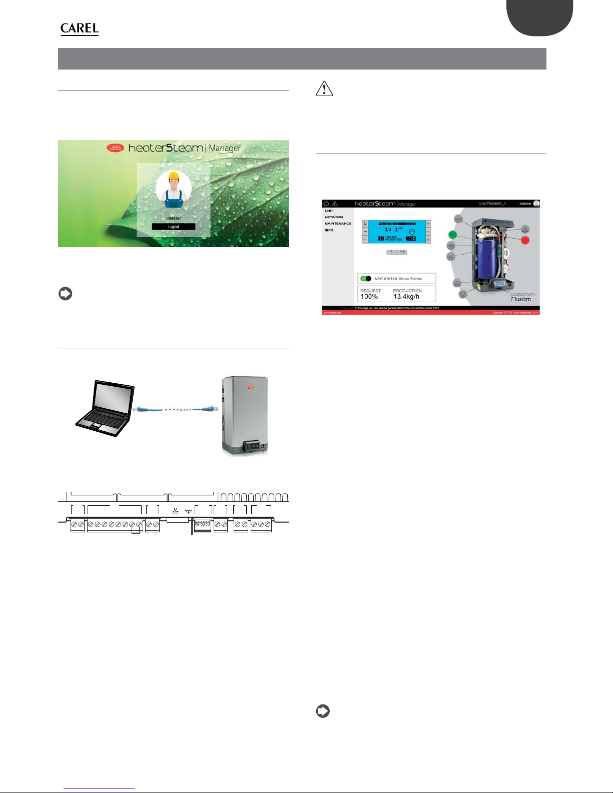
45
ENG
“heaterSteam” +0300080EN - rel. 1.0 - 27.04.2016
9. WEB SERVER
9.1 Integrated web server
The integrated web server is used to confi gure and monitor the main
unit parameters directly from a PC. In fact, using the Ethernet port on
the humidifi er controller, the unit can be accessed via a local network by
simply entering its IP address in the browser.
Fig. 9.a
To log in and access the various menu items, use the installer or service
password (see paragraph 6.12 “Main menu”).
Note: the web server is managed in the heaterSteam titanium
version.
9.2 Connecting to the integrated web server
For the physical connection to the controller from a PC, must use the RJ45
Ethernet port on the c.pHC and an Ethernet category 5 cable.
Fig. 9.b
The Ethernet port is available on the humidifi er’s c.pHC controller:
M2M9 M8 M1 M5 M6M12
1 1234567821132 31221212
Ethernet
Fig. 9.c
The PC and the humidifi er controller (or all controllers, for Master/Slave
systems) must be part of the same subnetwork.
The default network confi gurations for the c.pHC are:
unit’s IP address: 192.168.0.1
subnet mask: 255.255.255.0
gateway: 192.168.0.1
For example, the PC’s network settings can be changed as follows:
unit’s IP address: 192.168.0.2
subnet mask: 255.255.255.0
gateway: 192.168.0.1
To do this, access the “Network and sharing center” on the PC and go to
“Local network connection”. Then modify the addresses, as shown above,
for Internet protocol version 4.
Each c.pHC controller can obviously also be added to the Ethernet local
network, allowing the web server to be accessed from any point in the
network and for each humidifi er.
Important: the controller is not accessible directly on the internet
as a fi rewall guarantees remote access only via a secure connection (Carel
tERA cloud or encrypted VPN connection).
9.3 Description of the web server function
The web server “Home” page provides access to the display, so as to carry
out all the confi guration operations in the same way as if working directly
on the pGD. In addition, there will be an immediate response from unit
concerning its operation in the network.
Fig. 9.d
The main confi gurations and information are:
• UNIT
• NETWORK
• MAINTENANCE
• INFO
Unit menu
Probes: information and confi guration of the main and limit probe.
Select the type of signal and defi ne the minimum and maximum values.
Wireless: enable and associate each wireless probe to the main probe
group or limit probe group. Read the humidity and/or temperature, level
and battery status.
Control: select the control type. Set the set point, diff erential, minimum
and maximum.
Confi guration: confi gure the time and date. Confi gure the main alarms
and variation in percentages of fi ll and drain times.
Scheduler: enable and set the daily and weekly time bands.
Network menu
Display a summary of the status of the units in the advanced Master/
Slave system.
Maintenance
Timers: display cylinder and unit operating hours. Display the time
remaining until maintenance is required and set the maintenance prealert.
Logs: display the log of main variables (production, set point, drain pump
status, fi ll valve status, request, unit status).
Live: real time display of the main variables (production, set point, drain
pump status, fi ll valve status, request, unit status).
Info
Unit info: information on the unit model and software version. Select
language and unit of measure.
Resources: useful links (Carel website, heaterSteam manual and page on
Carel website).
Guide & FAQ: general information on using the web server.
Note: to avoid incorrect settings, some of the main unit operating
parameters can only be modifi ed via the web server when the unit is off
(off from keypad).

46
ENG
“heaterSteam” +0300080EN - rel. 1.0 - 27.04.2016
10. HARDWARE BACKUP
For applications that require continuous humidity control, a second
backup unit may be required, which is automatically activated in the
event of a malfunction on the fi rst.
The heaterSteam controller features a dedicated digital input and output
for the backup connection, so as to guarantee, via the normally-open
contact, activation of the second unit.
unit
backup
backup IN/OUT
Hardware
backup
Connection between two units for the hardware backup function:
terminal function
M9.1 Backup and rotation contact common
M9.2 Backup and rotation contact (NO)
M2.2 GND
M2.4 Backup / rotation digital input
Tab. 10.f
Fig. 10.a
Legenda:
M9.1 M2.2
M9.2 M2.4
M2.2 M9.1
M2.4 M9.2
M2M9
1 123456782
12345678
12
M2M9
Unit 1
Unit 2
Fig. 10.b
The hardware backup function must be activated on the menu in screen
Ee01. Screen Ee02 is used to set the unit with higher priority in the event
of simultaneous activation.
To ensure service continuity, the external signal or probes must be
connected to both units; in this way, both the main unit and the backup
unit will be completely independent. If using autonomous control
with probes, it is recommended to use dedicated probes for each unit
(main probe and limit probe), in other words, do not share the probes
between the units. This will guarantee service even in the event of probe
malfunctions.
Note: the hardware backup function is managed on the
heaterSteam titanium version.

47
ENG
“heaterSteam” +0300080EN - rel. 1.0 - 27.04.2016
11. SUPERVISOR NETWORK
11.1 Supervisor network protocols and
confi guration
The humidifi er can be connected to a supervisor via serial (BMS) or
Ethernet network. The Carel, ModBus and BACnet protocols are supported
as standard by the units.
M2M9 M8 M1 M5 M6M12
1 1234567821132 31221212
2
1
Ethernet
Fig. 11.a
Port Terminal on c.pHC controller Protocol
BMS (1) M12.1, M12.2, M12.3 Carel, ModBus, BACnet, Carel retro
Ethernet (2)
ModBus, BACnet
Tab. 11.a
To confi gure supervision on the BMS port (1), go to “SETTINGS –
SUPERVISION”, specifi cally screens Eh01, Eh02 and Eh03.
If connecting the supervisor to the Ethernet port (2), set the network
parameters (DHCP, IP address, subnet mask, gateway, DNS) on screen
Eh04.
For other supervisor protocols, select the Carel protocol on the BMS serial
port and use the Carel external gateway (supernode for humidifi cation:
SNU0000EM0) combined with the desired supervision card (depending
on the protocol).
Note: Ethernet CAT-5 STP cable, maximum length 100 m. To connect
the shield, use the earth connector provided on the controller.
Note: for BMS and Fieldbus, use shielded cables with the shield
connected to earth.
11.2 Table of supervisor variables
The variables shown in the lists below are only a set of all the internal variables on the heaterSteam humidifi er.
DO NOT CONFIGURE ANY VARIABLES THAT ARE NOT SHOWN IN THE TABLES TO AVOID RISKING INCORRECT HUMIDIFIER OPERATION.
11.2.1 Table of Carel variables
Below are the variables used by the Carel protocol.
Integer variables
Variable Variable name R/W Description Category
1 SV_SWVer R Software version Unit info
2 SV_OSVer R OS version
3 UnitModel R Model version
4 Conductivity R Conductivity I/O
5 WirelessPrbInfo_1.BattLev R Wireless probe 1: battery level Wireless probes
6 WirelessPrbInfo_1.RadioSignalLev R Wireless probe 1: wireless signal level
7 WirelessPrbInfo_2.BattLev R Wireless probe 2: battery level
8 WirelessPrbInfo_2.RadioSignalLev R Wireless probe 2: wireless signal level
9 WirelessPrbInfo_3.BattLev R Wireless probe 3: battery level
10 WirelessPrbInfo_3.RadioSignalLev R Wireless probe 3: wireless signal level
11 WirelessPrbInfo_4.BattLev R Wireless probe 4: battery level
12 WirelessPrbInfo_4.RadioSignalLev R Wireless probe 4: wireless signal level
13 UnitStatus R Unit status Unit status
14 WorkHr R Unit operating hours
15 CylWorkHr R Cylinder operating hours
19 RegulationCfg.RegTyp RW Control type Reg
20 ThrshAlrmDT RW High humidity/temperature alarm delay Alrm T
21 MainPrbCfg.Typ RW Main probe type Probes cfg
22 LimitPrbCfg.Typ RW Limit probe type
23 WHardnessMan RW Manual water hardness value (if WHardnessTyp is TRUE) Unit cfg
24 EvapCycleNoThrshsh RW Number of evaporation cycles (0=auto)
25 FillTScale RW Variation in fi ll time
26 DilDrainTScale RW Variation in drain time
27 Scheduler.SchedDayToSet RW When >0, day of the week to be confi gured (1=Monday, 7=Sunday) Scheduler setting
28 SchedDayCfg[0].StartHr RW Band 1 start hours
29 SchedDayCfg[0].StartMin RW Band 1 start minutes
30 SchedDayCfg[0].WorkMode RW Band 1 operating mode
31 SchedDayCfg[1].StartHr RW Band 2 start hours for
32 SchedDayCfg[1].StartMin RW Band 2 start minutes
33 SchedDayCfg[1].WorkMode RW Band 2 operating mode
34 SchedDayCfg[2].StartHr RW Band 3 start hours
35 SchedDayCfg[2].StartMin RW Band 3 start minutes
36 SchedDayCfg[2].WorkMode RW Band 3 operating mode
37 SchedDayCfg[3].StartHr RW Band 4 start hours
38 SchedDayCfg[3].StartMin RW Band 4 start minutes
39 SchedDayCfg[3].WorkMode RW Band 4 operating mode
40 SchedDayCfg[4].StartHr RW Band 5 start hours
41 SchedDayCfg[4].StartMin RW Band 5 start minutes
42 SchedDayCfg[4].WorkMode RW Band 5 operating mode
43 SchedDayCfg[5].StartHr RW Band 6 start hours
44 SchedDayCfg[5].StartMin RW Band 6 start minutes
45 SchedDayCfg[5].WorkMode RW Band 6 operating mode
46 UoM RW Unit of measure UoM

48
ENG
“heaterSteam” +0300080EN - rel. 1.0 - 27.04.2016
Variable Variable name R/W Description Category
47 Year RW Year Clock
48 Month RW Month
49 Day RW Day
50 Hour RW Hour
51 Minute RW Minutes
52 SetTimezone RW Time zone
53 NetStatus[1] R Unit 1 status Network
feedback
54 NetStatus[2] R Unit 2 status
55 NetStatus[3] R Unit 3 status
56 NetStatus[4] R Unit 4 status
57 NetStatus[5] R Unit 5 status
58 NetStatus[6] R Unit 6 status
59 NetStatus[7] R Unit 7 status
60 NetStatus[8] R Unit 8 status
61 NetStatus[9] R Unit 9 status
62 NetStatus[10] R Unit 10 status
63 NetStatus[11] R Unit 11 status
64 NetStatus[12] R Unit 12 status
65 NetStatus[13] R Unit 13 status
66 NetStatus[14] R Unit 14 status
67 NetStatus[15] R Unit 15 status
68 NetStatus[16] R Unit 16 status
69 NetStatus[17] R Unit 17 status
70 NetStatus[18] R Unit 18 status
71 NetStatus[19] R Unit 19 status
72 NetStatus[20] R Unit 20 status
93 SV_Command RW 1: reset alarms, 2: reset hour counter Comm
94 SV_CommandResult R 1: successful, 2: failed, 3: invalid command
Tab. 11.b
Analogue variables
Variable Variable name R/W Description Category
1 MainPrb R Main probe value (REAL) I/O
2 LimitPrb R Limit probe/second probe value (REAL)
3 PreheatPrb R NTC preheating probe value (REAL)
4 WirelessPrbVal_1.Hum R Wireless probe 1: Humidity Wireless probes
5 WirelessPrbVal_1.Temp R Wireless probe 1: Temperature
6 WirelessPrbVal_2.Hum R Wireless probe 2: Humidity
7 WirelessPrbVal_2.Temp R Wireless probe 2: Temperature
8 WirelessPrbVal_3.Hum R Wireless probe 3: Humidity
9 WirelessPrbVal_3.Temp R Wireless probe 3: Temperature
10 WirelessPrbVal_4.Hum R Wireless probe 4: Humidity
11 WirelessPrbVal_4.Temp R Wireless probe 4: Temperature
12 SV_PwrReq RW Production request percentage from supervisor Unit Status
13 CurrProdPh R Current production in kg/h (lbs/h)
15 GlbSetP_Hum RW Humidity control set point Regulation
16 GlbSetP_Temp RW Temperature control set point
17 RegulationCfg.Hyst RW Control hysteresis
18 RegulationCfg.Diff RW Control diff erential
19 GlbSetPLim_Hum RW Set point limit for humidity control
20 GlbSetPLim_Temp RW Set point limit for temperature control
21 RegulationCfg.Diff Lim RW Limit diff erential
22 RegulationCfg.MinReq RW Minimum production
23 AlrmThrshHumLo RW Low humidity alarm threshold Alarms Thresholds
24 AlrmThrshHumHi RW High humidity alarm threshold
25 AlrmThrshHumHiLim RW High humidity limit alarm threshold
26 AlrmThrshTempLo RW Low temperature alarm threshold
27 AlrmThrshTempHi RW High temperature alarm threshold
28 AlrmThrshTempHiLim RW High temperature limit alarm threshold
29 MainPrbCfg.Mi_Hum RW Main probe minimum humidity value Probes cfg
30 MainPrbCfg.Ma_Hum RW Main probe maximum humidity value
31 MainPrbCfg.Mi_Temp RW Main probe minimum temperature value
32 MainPrbCfg.Ma_Temp RW Main probe maximum temperature value
33 LimitPrbCfg.Mi_Hum RW Limit probe minimum humidity value
34 LimitPrbCfg.Ma_Hum RW Limit probe maximum humidity value
35 LimitPrbCfg.Mi_Temp RW Limit probe minimum temperature value
36 LimitPrbCfg.Ma_Temp RW Limit probe maximum temperature value
37 RegulationCfg.PwrCorrectionFactor RW Power correction for thermal dissipation Unit Cfg
38 SchedDayCfg[0].SetP RW Band 1 set point Scheduler
39 SchedDayCfg[1].SetP RW Band 2 set point
40 SchedDayCfg[2].SetP RW Band 3 set point
41 SchedDayCfg[3].SetP RW Band 4 set point
42 SchedDayCfg[4].SetP RW Band 5 set point
43 SchedDayCfg[5].SetP RW Band 6 set point
44 NetReq R Current system request Network feedback
45 NetProd R Current system production
Tab. 11.c

49
ENG
“heaterSteam” +0300080EN - rel. 1.0 - 27.04.2016
Digital variables
Variable Variable name R/W Description Category
1 RemOn R Remote on/off I/O
2 ThermPtcDin R Thermal DIN status
3 LevSenStatus.Low R Level sensor: low level
4 LevSenStatus.Hi R Level sensor: high level
5 LevSenStatus.Foam R High level sensor: foam
6 OnOff Status R Unit status On or OFF On/Off
7 OnBySV RW Start command from SV (Supervisor)
13 PreMaintWarn R Maintenance pre-alert (not an alarm) Alarms
14 CurrBlkAlrm.IsBlocker R Shutdown alarm
15 CurrBlkAlrm.IsPresent R Resettable alarm
16 CurrBlkAlrm.Warning R Warning
17 Alrm_Autotest.Active R Autotest alarm
18 Alrm_HighConductAl.Active R High conductivity alarm
19 Alrm_LevSen.Active R Level sensor broken alarm
20 Alrm_ThermPtc.Active R Thermal overload alarm
21 Alrm_Wmiss.Active R No water alarm
22 Alrm_LowProd.Active R Low production alarm
23 Alrm_MainPrb.Active R Main probe fault alarm
24 Alrm_LimPrb.Active R Limit probe fault alarm
25 Alrm_PreHPrb.Active R NTC preheating probe fault alarm
26 Alrm_HiHum.Active R High humidity alarm
27 Alrm_LoHum.Active R Low humidity alarm
28 Alrm_HiHumLim.Active R High humidity limit alarm
29 Alrm_Foam.Active R Foam alarm
30 Alrm_PeriodicMaint.Active R Periodical maintenance request
31 Alrm_CylFull.Active R Cylinder full alarm
32 Alrm_ConductPrb.Active R Conductivity probe fault alarm
33 Alrm_HighConductWr.Active R High conductivity warning
34 Alrm_RetMem.Active R Retain memory damaged warning
35 Warn_Autotest.Active R Autotest warning
36 Warn_LevSen.Active R Level sensor warning
37 Warn_LowProd.Active R Low production warning
38 Alrm_WirelessPrb_1_Offl ine.Active R Wireless probe 1 offl ine
39 Alrm_WirelessPrb_2_Offl ine.Active R Wireless probe 2 offl ine
40 Alrm_WirelessPrb_3_Offl ine.Active R Wireless probe 3 offl ine
41 Alrm_WirelessPrb_4_Offl ine.Active R Wireless probe 4 offl ine
42 Alrm_MissingModel.Active R Model not confi gured
43 Alrm_NetUnit_1.Active R Active alarm on unit 1
44 Alrm_NetUnit_2.Active R Active alarm on unit 2
45 Alrm_NetUnit_3.Active R Active alarm on unit 3
46 Alrm_NetUnit_4.Active R Active alarm on unit 4 Alarms
47 Alrm_NetUnit_5.Active R Active alarm on unit 5
48 Alrm_NetUnit_6.Active R Active alarm on unit 6
49 Alrm_NetUnit_7.Active R Active alarm on unit 7
50 Alrm_NetUnit_8.Active R Active alarm on unit 8
51 Alrm_NetUnit_9.Active R Active alarm on unit 9
52 Alrm_NetUnit_10.Active R Active alarm on unit 10
53 Alrm_NetUnit_11.Active R Active alarm on unit 11
54 Alrm_NetUnit_12.Active R Active alarm on unit 12
55 Alrm_NetUnit_13.Active R Active alarm on unit 13
56 Alrm_NetUnit_14.Active R Active alarm on unit 14
57 Alrm_NetUnit_15.Active R Active alarm on unit 15
58 Alrm_NetUnit_16.Active R Active alarm on unit 16
59 Alrm_NetUnit_17.Active R Active alarm on unit 17
60 Alrm_NetUnit_18.Active R Active alarm on unit 18
61 Alrm_NetUnit_19.Active R Active alarm on unit 19
62 Alrm_NetUnit_20.Active R Active alarm on unit 20
63 Alrm_WirelessPrb_1_LowBatt.Active R Wireless probe 1: Low battery level alarm
64 Alrm_WirelessPrb_2_LowBatt.Active R Wireless probe 2: Low battery level alarm
65 Alrm_WirelessPrb_3_LowBatt.Active R Wireless probe 3: Low battery level alarm
66 Alrm_WirelessPrb_4_LowBatt.Active R Wireless probe 4: Low battery level alarm
67 Alrm_WirelessPrb_Main.Active R Wireless probe fault (main group)
68 Alrm_WirelessPrb_Limit.Active R Wireless probe fault (limit group)
69 SchedDayCfg[0].EnTB RW Scheduler: Enable band 1 Scheduler
70 SchedDayCfg[1].EnTB RW Scheduler: Enable band 2
71 SchedDayCfg[2].EnTB RW Scheduler: Enable band 3
72 SchedDayCfg[3].EnTB RW Scheduler: Enable band 4
73 SchedDayCfg[4].EnTB RW Scheduler: Enable band 5
74 SchedDayCfg[5].EnTB RW Scheduler: Enable band 6
Tab. 11.d
Note: for existing supervisors, a table has been created for backward
compatibility, contact Carel for the list (Carel retro).

50
ENG
“heaterSteam” +0300080EN - rel. 1.0 - 27.04.2016
11.2.2 Table of ModBus variables
Below are the variables used by the Modbus protocol.
INPUT REGISTERS
Variable Variable name Occup. Description Category
1 SV_SWVer 1 Software version Unit info
2 SV_OSVer 1 OS version
3 UnitModel 1 Model version
4 MainPrb 2 Main probe value (REAL) I/O
6 LimitPrb 2 Limit probe/second probe value (REAL)
8 PreheatPrb 2 NTC preheating probe value (REAL)
10 Conductivity 1 Conductivity
11 WirelessPrbVal_1.Hum 2 Wireless probe 1: Humidity Wireless probes read
13 WirelessPrbVal_1.Temp 2 Wireless probe 1: Temperature
15 WirelessPrbInfo_1.BattLev 1 Wireless probe 1: battery level
16 WirelessPrbInfo_1.RadioSignalLev 1 Wireless probe 1: wireless signal level
17 WirelessPrbVal_2.Hum 2 Wireless probe 2: Humidity
19 WirelessPrbVal_2.Temp 2 Wireless probe 2: Temperature
21 WirelessPrbInfo_2.BattLev 1 Wireless probe 2: battery level
22 WirelessPrbInfo_2.RadioSignalLev 1 Wireless probe 2: wireless signal level
23 WirelessPrbVal_3.Hum 2 Wireless probe 3: Humidity
25 WirelessPrbVal_3.Temp 2 Wireless probe 3: Temperature
27 WirelessPrbInfo_3.BattLev 1 Wireless probe 3: battery level
28 WirelessPrbInfo_3.RadioSignalLev 1 Wireless probe 3: wireless signal level
29 WirelessPrbVal_4.Hum 2 Wireless probe 4: Humidity
31 WirelessPrbVal_4.Temp 2 Wireless probe 4: Temperature
33 WirelessPrbInfo_4.BattLev 1 Wireless probe 4: battery level
34 WirelessPrbInfo_4.RadioSignalLev 1 Wireless probe 4: wireless signal level
35 UnitStatus 1 Unit status Unit status
36 CurrProdPh 2 Current production in kg/h (lbs/h)
38 WorkHr 2 Unit operating hours
40 CylWorkHr 2 Cylinder operating hours
42 NetReq 2 Current system request Network feedback
44 NetProd 2 Current system production
46 NetStatus[1] 1 Unit 1 status
47 NetStatus[2] 1 Unit 2 status
48 NetStatus[3] 1 Unit 3 status
49 NetStatus[4] 1 Unit 4 status
50 NetStatus[5] 1 Unit 5 status
51 NetStatus[6] 1 Unit 6 status
52 NetStatus[7] 1 Unit 7 status
53 NetStatus[8] 1 Unit 8 status
54 NetStatus[9] 1 Unit 9 status
55 NetStatus[10] 1 Unit 10 status
56 NetStatus[11] 1 Unit 11 status
57 NetStatus[12] 1 Unit 12 status
58 NetStatus[13] 1 Unit 13 status
59 NetStatus[14] 1 Unit 14 status
60 NetStatus[15] 1 Unit 15 status
61 NetStatus[16] 1 Unit 16 status Network feedback
62 NetStatus[17] 1 Unit 17 status
63 NetStatus[18] 1 Unit 18 status
64 NetStatus[19] 1 Unit 19 status
65 NetStatus[20] 1 Unit 20 status
106 SV_CommandResult 1 1: successful, 2: failed, 3: invalid command Comm
Tab. 11.e
HOLDING REGISTERS
Variable Variable name Occup. Description Category
1 SV_PwrReq 2 Production request percentage from supervisor Unit st.
8 RegulationCfg.RegTyp 1 Control type Regulation
9 GlbSetP_Hum 2 Humidity control set point
11 GlbSetP_Temp 2 Temperature control set point
13 RegulationCfg.Hyst 2 Control hysteresis
15 RegulationCfg.Diff 2 Control diff erential
17 GlbSetPLim_Hum 2 Set point limit for humidity control
19 GlbSetPLim_Temp 2 Set point limit for temperature control
21 RegulationCfg.Diff Lim 2 Limit diff erential
23 RegulationCfg.MinReq 2 Minimum production
25 AlrmThrshHumLo 2 Low humidity alarm threshold Alarm thresholds
27 AlrmThrshHumHi 2 High humidity alarm threshold
29 AlrmThrshHumHiLim 2 High humidity limit alarm threshold
31 AlrmThrshTempLo 2 Low temperature alarm threshold
33 AlrmThrshTempHi 2 High temperature alarm threshold
35 AlrmThrshTempHiLim 2 High temperature limit alarm threshold
37 ThrshAlrmDT 1 High humidity/temperature alarm delay
38 MainPrbCfg.Typ 1 Main probe type Probes cfg
39 MainPrbCfg.Mi_Hum 2 Main probe minimum humidity value
41 MainPrbCfg.Ma_Hum 2 Main probe maximum humidity value
43 MainPrbCfg.Mi_Temp 2 Main probe minimum temperature value
45 MainPrbCfg.Ma_Temp 2 Main probe maximum temperature value
47 LimitPrbCfg.Typ 1 Limit probe type
48 LimitPrbCfg.Mi_Hum 2 Limit probe minimum humidity value
50 LimitPrbCfg.Ma_Hum 2 Limit probe maximum humidity value
52 LimitPrbCfg.Mi_Temp 2 Limit probe minimum temperature value
54 LimitPrbCfg.Ma_Temp 2 Limit probe maximum temperature value
56 WHardnessMan 1 Manual water hardness value (if WHardnessTyp is TRUE) Unit cfg
57 EvapCycleNoThrshsh 1 Number of evaporation cycles (0=auto)
58 FillTScale 1 Variation in fi ll time
59 DilDrainTScale 1 Variation in drain time
60 RegulationCfg.PwrCorrectionFactor 2 Power correction for thermal dissipation

51
ENG
“heaterSteam” +0300080EN - rel. 1.0 - 27.04.2016
Variable Variable name Occup. Description Category
62 Scheduler.SchedDayToSet 1 When >0, day of the week to be confi gured (1=Monday, 7=Sunday) Scheduler setting
63 SchedDayCfg[0].StartHr 1 Band 1 start hours
64 SchedDayCfg[0].StartMin 1 Band 1 start minutes
65 SchedDayCfg[0].WorkMode 1 Band 1 operating mode
66 SchedDayCfg[0].SetP 2 Band 1 set point
68 SchedDayCfg[1].StartHr 1 Band 2 start hours
69 SchedDayCfg[1].StartMin 1 Band 2 start minutes
70 SchedDayCfg[1].WorkMode 1 Band 2 operating mode
71 SchedDayCfg[1].SetP 2 Band 2 set point
73 SchedDayCfg[2].StartHr 1 Band 3 start hours
74 SchedDayCfg[2].StartMin 1 Band 3 start minutes
75 SchedDayCfg[2].WorkMode 1 Band 3 operating mode
76 SchedDayCfg[2].SetP 2 Band 3 set point
78 SchedDayCfg[3].StartHr 1 Band 4 start hours
79 SchedDayCfg[3].StartMin 1 Band 4 start minutes
80 SchedDayCfg[3].WorkMode 1 Band 4 operating mode
81 SchedDayCfg[3].SetP 2 Band 4 set point
83 SchedDayCfg[4].StartHr 1 Band 5 start hours
84 SchedDayCfg[4].StartMin 1 Band 5 start minutes
85 SchedDayCfg[4].WorkMode 1 Band 5 operating mode
86 SchedDayCfg[4].SetP 2 Band 5 set point
88 SchedDayCfg[5].StartHr 1 Band 6 start hours
89 SchedDayCfg[5].StartMin 1 Band 6 start minutes
90 SchedDayCfg[5].WorkMode 1 Band 6 operating mode
91 SchedDayCfg[5].SetP 2 Band 6 set point
93 UoM 1 Unit of measure UoM
94 Year 1 Year Clock
95 Month 1 Month
96 Day 1 Day
97 Hour 1 Hour
98 Minute 1 Minutes
99 SetTimezone 1 Time zone
100 SV_Command 1 1: reset alarms, 2: reset hour counter Comm
Tab. 11.f
INPUT STATUS
Variable Variable name Occup. Description Category
1 RemOn 1 Remote on/off I/O
2 ThermPtcDin 1 Thermal DIN status
3 LevSenStatus.Low 1 Level sensor: low level
4 LevSenStatus.Hi 1 Level sensor: high level
5 LevSenStatus.Foam 1 High level sensor: foam
6 OnOff Status 1 Unit status On or OFF On/Off
7 PreMainWarn 1 Maintenance pre-alert (not an alarm) Alarms
8 CurrBlkAlrm.IsBlocker 1 Shutdown alarm
9 CurrBlkAlrm.IsPresent 1 Resettable alarm
10 CurrBlkAlrm.Warning 1 Warning
11 Alrm_Autotest.Active 1 Autotest alarm
12 Alrm_HighConductAl.Active 1 High conductivity alarm
13 Alrm_LevSen.Active 1 Level sensor broken alarm
14 Alrm_ThermPtc.Active 1 Thermal overload alarm
15 Alrm_Wmiss.Active 1 No water alarm
16 Alrm_LowProd.Active 1 Low production alarm
17 Alrm_MainPrb.Active 1 Main probe fault alarm
18 Alrm_LimPrb.Active 1 Limit probe fault alarm
19 Alrm_PreHPrb.Active 1 NTC preheating probe fault alarm
20 Alrm_HiHum.Active 1 High humidity alarm
21 Alrm_LoHum.Active 1 Low humidity alarm
22 Alrm_HiHumLim.Active 1 High humidity limit alarm
23 Alrm_Foam.Active 1 Foam alarm
24 Alrm_PeriodicMaint.Active 1 Periodical maintenance request
25 Alrm_CylFull.Active 1 Cylinder full alarm
26 Alrm_ConductPrb.Active 1 Conductivity probe fault alarm
27 Alrm_HighConductWr.Active 1 High conductivity warning
28 Alrm_RetMem.Active 1 Retain memory damaged warning
29 Warn_Autotest.Active 1 Autotest warning
30 Warn_LevSen.Active 1 Level sensor warning
31 Warn_LowProd.Active 1 Low production warning
32 Alrm_WirelessPrb_1_Offl ine.Active 1 Wireless probe 1 offl ine
33 Alrm_WirelessPrb_2_Offl ine.Active 1 Wireless probe 2 offl ine
34 Alrm_WirelessPrb_3_Offl ine.Active 1 Wireless probe 3 offl ine
35 Alrm_WirelessPrb_4_Offl ine.Active 1 Wireless probe 4 offl ine
36 Alrm_MissingModel.Active 1 Model not confi gured
37 Alrm_NetUnit_1.Active 1 Active alarm on unit 1
38 Alrm_NetUnit_2.Active 1 Active alarm on unit 2
39 Alrm_NetUnit_3.Active 1 Active alarm on unit 3
40 Alrm_NetUnit_4.Active 1 Active alarm on unit 4
41 Alrm_NetUnit_5.Active 1 Active alarm on unit 5
42 Alrm_NetUnit_6.Active 1 Active alarm on unit 6
43 Alrm_NetUnit_7.Active 1 Active alarm on unit 7
44 Alrm_NetUnit_8.Active 1 Active alarm on unit 8
45 Alrm_NetUnit_9.Active 1 Active alarm on unit 9
46 Alrm_NetUnit_10.Active 1 Active alarm on unit 10
47 Alrm_NetUnit_11.Active 1 Active alarm on unit 11
48 Alrm_NetUnit_12.Active 1 Active alarm on unit 12
49 Alrm_NetUnit_13.Active 1 Active alarm on unit 13
50 Alrm_NetUnit_14.Active 1 Active alarm on unit 14
51 Alrm_NetUnit_15.Active 1 Active alarm on unit 15
52 Alrm_NetUnit_16.Active 1 Active alarm on unit 16
53 Alrm_NetUnit_17.Active 1 Active alarm on unit 17
54 Alrm_NetUnit_18.Active 1 Active alarm on unit 18
52
ENG
“heaterSteam” +0300080EN - rel. 1.0 - 27.04.2016
Variable Variable name Occup. Description Category
55 Alrm_NetUnit_19.Active 1 Active alarm on unit 19 Alarms
56 Alrm_NetUnit_20.Active 1 Active alarm on unit 20
57 Alrm_WirelessPrb_1_LowBatt.Active 1 Wireless probe 1: Low battery level alarm
58 Alrm_WirelessPrb_2_LowBatt.Active 1 Wireless probe 2: Low battery level alarm
59 Alrm_WirelessPrb_3_LowBatt.Active 1 Wireless probe 3: Low battery level alarm
60 Alrm_WirelessPrb_4_LowBatt.Active 1 Wireless probe 4: Low battery level alarm
61 Alrm_WirelessPrb_Main.Active 1 Wireless probe fault (main group)
62 Alrm_WirelessPrb_Limit.Active 1 Wireless probe fault (limit group)
Tab. 11.g
COIL STATUS
Variable Variable name Occup. Description Category
1 OnBySV 1 Start command from SV (Supervisor) On/Off
7 SchedDayCfg[0].EnTB 1 Scheduler: Enable band 1 Scheduler
8 SchedDayCfg[1].EnTB 1 Scheduler: Enable band 2
9 SchedDayCfg[2].EnTB 1 Scheduler: Enable band 3
10 SchedDayCfg[3].EnTB 1 Scheduler: Enable band 4
11 SchedDayCfg[4].EnTB 1 Scheduler: Enable band 5
12 SchedDayCfg[5].EnTB 1 Scheduler: Enable band 6
Tab. 11.h
11.2.3 Table of BACnet variables
Below are the variables used by the BACnet protocol.
Positive Integer Values
Variable Variable name Access Description Category
0 SV_SWVer R Software version Unit info
1 SV_OSVer R OS version
2 UnitModel R Model version
3 Conductivity R Conductivity Inputs
4 WirelessPrbInfo_1.BattLev R Wireless probe 1: battery level Wireless probes
5 WirelessPrbInfo_1.RadioSignalLev R Wireless probe 1: wireless signal level
6 WirelessPrbInfo_2.BattLev R Wireless probe 2: battery level
7 WirelessPrbInfo_2.RadioSignalLev R Wireless probe 2: wireless signal level
8 WirelessPrbInfo_3.BattLev R Wireless probe 3: battery level
9 WirelessPrbInfo_3.RadioSignalLev R Wireless probe 3: wireless signal level
10 WirelessPrbInfo_4.BattLev R Wireless probe 4: battery level
11 WirelessPrbInfo_4.RadioSignalLev R Wireless probe 4: wireless signal level
12 UnitStatus R Unit status Unit status
13 WorkHr R Unit operating hours
14 CylWorkHr R Cylinder operating hours
15 ManMode RW Manual mode (1=outputs, 2=request) Manual
16 ManSSR_OpT RW SSR opening time (manual mode)
17 ManSSR_ClT RW SSR closing time (manual mode)
18 RegulationCfg.RegTyp RW Control type Reg cfg
19 ThrshAlrmDT RW High humidity/temperature alarm delay Alrm thr.
20 MainPrbCfg.Typ RW Main probe type IO cfg
21 LimitPrbCfg.Typ RW Limit probe type
22 WHardnessMan RW Manual water hardness value (if WHardnessTyp is TRUE) Unit cfg
23 EvapCycleNoThrshsh RW Number of evaporation cycles (0=auto)
24 FillTScale RW Variation in fi ll time
25 DilDrainTScale RW Variation in drain time
26 Scheduler.SchedDayToSet RW When >0, day of the week to be confi gured (1=Monday, 7=Sunday) Scheduler
27 SchedDayCfg[0].StartHr RW Band 1 start hours
28 SchedDayCfg[0].StartMin RW Band 1 start minutes
29 SchedDayCfg[0].WorkMode RW Band 1 operating mode
30 SchedDayCfg[1].StartHr RW Band 2 start hours
31 SchedDayCfg[1].StartMin RW Band 2 start minutes
32 SchedDayCfg[1].WorkMode RW Band 2 operating mode
33 SchedDayCfg[2].StartHr RW Band 3 start hours
34 SchedDayCfg[2].StartMin RW Band 3 start minutes
35 SchedDayCfg[2].WorkMode RW Band 3 operating mode
36 SchedDayCfg[3].StartHr RW Band 4 start hours
37 SchedDayCfg[3].StartMin RW Band 4 start minutes
38 SchedDayCfg[3].WorkMode RW Band 4 operating mode
39 SchedDayCfg[4].StartHr RW Band 5 start hours
40 SchedDayCfg[4].StartMin RW Band 5 start minutes
41 SchedDayCfg[4].WorkMode RW Band 5 operating mode
42 SchedDayCfg[5].StartHr RW Band 6 start hours
43 SchedDayCfg[5].StartMin RW Band 6 start minutes
44 SchedDayCfg[5].WorkMode RW Band 6 operating mode
45 UoM RW Unit of measure UoM
46 Year RW Year Clock
47 Month RW Month
48 Day RW Day
49 Hour RW Hour
50 Minute RW Minutes
51 SetTimezone RW Time zone

53
ENG
“heaterSteam” +0300080EN - rel. 1.0 - 27.04.2016
Variable Variable name Access Description Category
52 NetStatus[1] R Unit 1 status Network
53 NetStatus[2] R Unit 2 status
54 NetStatus[3] R Unit 3 status
55 NetStatus[4] R Unit 4 status
56 NetStatus[5] R Unit 5 status
57 NetStatus[6] R Unit 6 status
58 NetStatus[7] R Unit 7 status
59 NetStatus[8] R Unit 8 status
60 NetStatus[9] R Unit 9 status
61 NetStatus[10] R Unit 10 status
62 NetStatus[11] R Unit 11 status
63 NetStatus[12] R Unit 12 status
64 NetStatus[13] R Unit 13 status
65 NetStatus[14] R Unit 14 status
66 NetStatus[15] R Unit 15 status
67 NetStatus[16] R Unit 16 status
68 NetStatus[17] R Unit 17 status
69 NetStatus[18] R Unit 18 status
70 NetStatus[19] R Unit 19 status
71 NetStatus[20] R Unit 20 status
92 SV_Command RW 1: reset alarms, 2: reset hour counter Comm
93 SV_CommandResult R 1: successful, 2: failed, 3: invalid command
Tab. 11.a
Analog values
Variable Variable name Access Description Category
0 MainPrb R Main probe value (REAL) Inputs
1 LimitPrb R Limit probe/second probe value (REAL)
2 PreheatPrb R NTC preheating probe value (REAL)
3 WirelessPrbVal_1.Hum R Wireless probe 1: Humidity Wireless probes
4 WirelessPrbVal_1.Temp R Wireless probe 1: Temperature
5 WirelessPrbVal_2.Hum R Wireless probe 2: Humidity
6 WirelessPrbVal_2.Temp R Wireless probe 2: Temperature
7 WirelessPrbVal_3.Hum R Wireless probe 3: Humidity
8 WirelessPrbVal_3.Temp R Wireless probe 3: Temperature
9 WirelessPrbVal_4.Hum R Wireless probe 4: Humidity
10 WirelessPrbVal_4.Temp R Wireless probe 4: Temperature
11 SV_PwrReq RW Production request percentage from supervisor Unit status
12 CurrProdPh R Current production in kg/h (lbs/h)
13 ManReq RW Manual request Manual
14 GlbSetP_Hum RW Humidity control set point Regulation
15 GlbSetP_Temp RW Temperature control set point
16 RegulationCfg.Hyst RW Control hysteresis
17 RegulationCfg.Diff RW Control diff erential
18 GlbSetPLim_Hum RW Set point limit for humidity control
19 GlbSetPLim_Temp RW Set point limit for temperature control
20 RegulationCfg.Diff Lim RW Limit diff erential
21 RegulationCfg.MinReq RW Minimum production
22 AlrmThrshHumLo RW Low humidity alarm threshold Alarm threshold
23 AlrmThrshHumHi RW High humidity alarm threshold
24 AlrmThrshHumHiLim RW High humidity limit alarm threshold
25 AlrmThrshTempLo RW Low temperature alarm threshold
26 AlrmThrshTempHi RW High temperature alarm threshold
27 AlrmThrshTempHiLim RW High temperature limit alarm threshold
28 MainPrbCfg.Mi_Hum RW Main probe minimum humidity value IO cfg
29 MainPrbCfg.Ma_Hum RW Main probe maximum humidity value
30 MainPrbCfg.Mi_Temp RW Main probe minimum temperature value
31 MainPrbCfg.Ma_Temp RW Main probe maximum temperature value
32 LimitPrbCfg.Mi_Hum RW Limit probe minimum humidity value
33 LimitPrbCfg.Ma_Hum RW Limit probe maximum humidity value
34 LimitPrbCfg.Mi_Temp RW Limit probe minimum temperature value
35 LimitPrbCfg.Ma_Temp RW Limit probe maximum temperature value
36 RegulationCfg.PwrCorrectionFactor RW Power correction for thermal dissipation Unit cfg
37 SchedDayCfg[0].SetP RW Band 1 set point Scheduler
38 SchedDayCfg[1].SetP RW Band 2 set point
39 SchedDayCfg[2].SetP RW Band 3 set point
40 SchedDayCfg[3].SetP RW Band 4 set point
41 SchedDayCfg[4].SetP RW Band 5 set point
42 SchedDayCfg[5].SetP RW Band 6 set point
43 NetReq R Current system request Network feedback
44 NetProd R Current system production
Tab. 11.i

54
ENG
“heaterSteam” +0300080EN - rel. 1.0 - 27.04.2016
Binary Values
Variable Variable name Access Description Category
0 RemOn R Remote on/off I/O
1 ThermPtcDin R Thermal DIN status
2 LevSenStatus.Low R Level sensor: low level
3 LevSenStatus.Hi R Level sensor: high level
4 LevSenStatus.Foam R High level sensor: foam
5 OnOff Status R Unit status On or OFF On/Off
6 OnBySV RW Start command from SV (Supervisor)
12 PreMainWarn R Maintenance pre-alert (not an alarm) Alarms
13 CurrBlkAlrm.IsBlocker R Shutdown alarm
14 CurrBlkAlrm.IsPresent R Resettable alarm
15 CurrBlkAlrm.Warning R Warning
16 Alrm_Autotest.Active R Autotest alarm
17 Alrm_HighConductAl.Active R High conductivity alarm
18 Alrm_LevSen.Active R Level sensor broken alarm
19 Alrm_ThermPtc.Active R Thermal overload alarm
20 Alrm_Wmiss.Active R No water alarm
21 Alrm_LowProd.Active R Low production alarm
22 Alrm_MainPrb.Active R Main probe fault alarm
23 Alrm_LimPrb.Active R Limit probe fault alarm
24 Alrm_PreHPrb.Active R NTC preheating probe fault alarm
25 Alrm_HiHum.Active R High humidity alarm
26 Alrm_LoHum.Active R Low humidity alarm
27 Alrm_HiHumLim.Active R High humidity limit alarm
28 Alrm_Foam.Active R Foam alarm
29 Alrm_PeriodicMaint.Active R Periodical maintenance request
30 Alrm_CylFull.Active R Cylinder full alarm
31 Alrm_ConductPrb.Active R Conductivity probe fault alarm
32 Alrm_HighConductWr.Active R High conductivity warning
33 Alrm_RetMem.Active R Retain memory damaged warning
34 Warn_Autotest.Active R Autotest warning
35 Warn_LevSen.Active R Level sensor warning
36 Warn_LowProd.Active R Low production warning
37 Alrm_WirelessPrb_1_Offl ine.Active R Wireless probe 1 offl ine
38 Alrm_WirelessPrb_2_Offl ine.Active R Wireless probe 2 offl ine
39 Alrm_WirelessPrb_3_Offl ine.Active R Wireless probe 3 offl ine Alarms
40 Alrm_WirelessPrb_4_Offl ine.Active R Wireless probe 4 offl ine
41 Alrm_MissingModel.Active R Model not confi gured
42 Alrm_NetUnit_1.Active R Active alarm on unit 1
43 Alrm_NetUnit_2.Active R Active alarm on unit 2
44 Alrm_NetUnit_3.Active R Active alarm on unit 3
45 Alrm_NetUnit_4.Active R Active alarm on unit 4
46 Alrm_NetUnit_5.Active R Active alarm on unit 5
47 Alrm_NetUnit_6.Active R Active alarm on unit 6
48 Alrm_NetUnit_7.Active R Active alarm on unit 7
49 Alrm_NetUnit_8.Active R Active alarm on unit 8
50 Alrm_NetUnit_9.Active R Active alarm on unit 9
51 Alrm_NetUnit_10.Active R Active alarm on unit 10
52 Alrm_NetUnit_11.Active R Active alarm on unit 11
53 Alrm_NetUnit_12.Active R Active alarm on unit 12
54 Alrm_NetUnit_13.Active R Active alarm on unit 13
55 Alrm_NetUnit_14.Active R Active alarm on unit 14
56 Alrm_NetUnit_15.Active R Active alarm on unit 15
57 Alrm_NetUnit_16.Active R Active alarm on unit 16
58 Alrm_NetUnit_17.Active R Active alarm on unit 17
59 Alrm_NetUnit_18.Active R Active alarm on unit 18
60 Alrm_NetUnit_19.Active R Active alarm on unit 19
61 Alrm_NetUnit_20.Active R Active alarm on unit 20
62 Alrm_WirelessPrb_1_LowBatt.Active R Wireless probe 1: Low battery level alarm
63 Alrm_WirelessPrb_2_LowBatt.Active R Wireless probe 2: Low battery level alarm
64 Alrm_WirelessPrb_3_LowBatt.Active R Wireless probe 3: Low battery level alarm
65 Alrm_WirelessPrb_4_LowBatt.Active R Wireless probe 4: Low battery level alarm
66 Alrm_WirelessPrb_Main.Active R Wireless probe fault (main group)
67 Alrm_WirelessPrb_Limit.Active R Wireless probe fault (limit group)
68 SchedDayCfg[0].EnTB RW Scheduler: Enable band 1 Scheduler
69 SchedDayCfg[1].EnTB RW Scheduler: Enable band 2
70 SchedDayCfg[2].EnTB RW Scheduler: Enable band 3
71 SchedDayCfg[3].EnTB RW Scheduler: Enable band 4
72 SchedDayCfg[4].EnTB RW Scheduler: Enable band 5
73 SchedDayCfg[5].EnTB RW Scheduler: Enable band 6
Tab. 11.j

55
ENG
“heaterSteam” +0300080EN - rel. 1.0 - 27.04.2016
The address to be used by the Access Point is set using the dipswitches
on the device, and is the following:
DIP:
1 2 3 4
++
G
--
Rx- Rx+ GND
L1
L2L3
T1
DIP 1-2-3 selezione indirizzo di rete
DIP 4 selezione baud di rete
Dipswitch Access
Point add.
Serial port baud rate
(Bit/S) N82
1234
2 19200
OFF ON OFF ON
Fig. 12.c
This assigns the address 2 to the Access Point, with a baud rate (Bit/sec)
of 19200 (N82). The addresses of the four serial probes, on the other hand,
must be set as shown in the table below:
Address Dipswitch
12345678
Probe 1 16 0 0 0 0 1 0 0 0
Probe 2 17 1 0 0 0 1 0 0 0
Probe 3 18 0 1 0 0 1 0 0 0
Probe 4 19 1 1 0 0 1 0 0 0
Tab. 12.l
Remember to verify the quality of the wireless signal between the Access
Point and each wireless probe.
For a complete description of the installation procedure, see the Carel
manual on the corresponding probes and Access Point.
To confi gure the probes, go the screens: Ec03, Ec04, Ec05, Ec06 and Ec07,
described in paragraph 7.4.3 “Wireless probes”.
In particular, screen Ec03 is used to enable the wireless probes connected
to the Access Point, knowing that addresses 16, 17, 18 and 19 are Probe 1,
Probe 2, Probe 3 and Probe 4 respectively.
Address: 16
Address: 17
Address: 18
Address: 19
Note: the wireless probes are managed on the heaterSteam
titanium version.
12. WIRELESS PROBES, INSTALLATION AND CONFIGURATION
Recommended Carel wireless probes are the room (WS01G01M00) or
industrial versions (WS01F01M00), both of which measure humidity
and temperature. The type of installation is shown in the fi gure below
(referring to four wireless room probes):
2
1
4
3
Key:
1. HeaterSteam humidifi er;
2. humidifi er/Access Point connection;
3. Access Point (WS01AB2M20);
4. Wireless probes for measuring
temperature and humidity (WS01G01M00
or WS01F01M00).
Fig. 12.b
HeaterSteam/Access point connection:
To connect the humidifi er to the access point, use the Fieldbus
connection on terminal M3 (M3.1: Tx/Rx-, M3.2: Tx/Rx+, M3.3: GND):
Note: the devices have a range of around a hundred metres in a free
space, i.e. without any obstacles. In a closed space, the range varies
considerably depending on the type of environment and the surrounding
objects (shelves, metal partition walls etc.).
If installing multiple wireless probes, the controller will calculate the
weighted average between the various probe readings, depending on
the settings made by the user and the defi ned probe groups. Also see
paragraph 7.4.3 Wireless probes. The controller also displays (locally only)
the battery and signal level for each probe (screen index D05-D08).
The table below shows the part numbers and descriptions of the Carel
devices that can be used:
P/N Model Features Power supply
WS01F01M00
SI Probe Temperature/
humidity for
industrial use
Battery
WS01G01M00
SA probe Room
temperature/
humidity
Battery
WS01AB2M20
Access
Point
Wireless gateway ZigBee™ –
RS485 ModBus
12/24 Vac/dc ±10%
100 mA; 50/60 Hz;
Use a Class II safety
transformer with
minimum power
rating of 2 VA. A 12
Vac transformer is
recommended
Tab. 12.k
12.2 Wireless probe installation
The main steps for installing the wireless devices are:
• power up the Access Point (12/24 Vac/dc ±10%m, 100mA) and
complete the initialisation procedure, creating the network and
selecting the channel;
• after having opened the domain on the Access Point, complete the
binding procedure so as to uniquely identify each probe.
12.1 Type of installation and wireless probe
electrical connections
Wireless probes are available for systems where standard wired probes
cannot be used, for example modifi cations to existing installations. An
Access Point (CAREL P/N: WS01AB2M20) is used to connect up to four
wireless probes.

56
ENG
“heaterSteam” +0300080EN - rel. 1.0 - 27.04.2016
13. ALARM TABLE
The following table shows the alarms that can be displayed by the controller, with the corresponding description, causes and possible solutions.
Alarm Cause Possible solution Reset Alarm relay Action
Autotest failed
alarm
Probable problems with:
feedwater, level control, fi ll solenoid
valve
Note: check the alarm log for any
warnings relating to the events that
generated the alarm (autotest warning,
level sensor warning, low production
warning)
Make sure that the unit receives water
Switch the unit off and clean the level control and the fi ll
valve
Restart required Closed Total
shutdown
High conductivity
warning
High water conductivity warning Check feedwater conductivity
If necessary, feature a suitable water treatment system
The problem cannot be solved by softening the feedwater
Manually reset the
warning
Open Signal only
High conductivity
alarm
High feedwater conductivity alarm Switch the unit off and clean the electrodes that measure the
water conductivity
If the problem persists, change the origin of the feedwater or
feature a suitable treatment system (demineralisation, even
partial)
The problem cannot be solved by softening the feedwater
Restart
required
Closed
Level sensor
malfunction alarm
The level sensor may not be working
correctly
Switch the unit off and clean the cylinder, the level sensor
and the fi ll solenoid valve
Check correct water supply to the cylinder
Restart required Closed Total
shutdown
Motor protector
alarm
The PTC probes in the heaters have
measured an excess temperature
Klixon activated
Manually reset the Klixon
The problem depends on operation without water or excessive scale on the surface of the heaters
Switch the unit off and, when it has cooled down, clean the
cylinder, the heaters and the level control, making sure the
components are intact
Check that the electrical and water connections are in order
and that the unit is powered correctly
It may be necessary to replace the PTC sensors
Stop - restart
required
Closed Total
shutdown
No water alarm No feedwater Check that the supply pipe to the humidifi er and the internal
tubing are not blocked or choked and that there is enough
pressure (0.1-0.8 MPa, 1-8 bars)
Check operation of the fi ll solenoid valve
Check that there is not excessive back-pressure in the steam
outlet, preventing water from entering the cylinder due to
gravity
Check that the steam outlet pipe is not choked or that there
are no pockets of condensate
Check that the level sensor is working correctly, clean if
necessary
Manual/ Automatic
Closed Stop
production
Low production
alarm
Input power not available; with the unit
on, there is no steam production or
water preheating;
Float blocked in high level position.
With the unit off and disconnected from the mains power
supply, check that there are no defective or faulty electrical
connections
Check electrical continuity of the heaters
Clean the level sensor
Manual Closed Stop
production
Main probe broken
or disconnected
alarm
Main room probe not connected or
damaged
Check probe connection and the type of control selected Manual Closed Stop
production
Limit probe broken
or disconnected
alarm
Limit probe or second probe not connected or damaged
Check probe connection and the type of control selected the
type of control choice
Manual Closed Stop
production
Pre-heating probe
broken or disconnected alarm
NTC water temperature probe not
connected or damaged
Check preheating operation and the settings of the parameters on screen eb02;
Automatic Closed Stop
production
High humidity/
temperature
warning
High humidity in the room (high temperature with temperature control)
Check operation of the probe and the limits set on screen c01 Automatic Open Signal only
Low humidity
warning
Low humidity in the room Check operation of the probe and the limits set on screen c01 Automatic Open Signal only
High limit humidity
warning
High humidity at outlet Check the operation of the outlet limit probe Automatic Open Signal only
Foam warning Entrainment of foam in the cylinder
during boiling
The entrainment of foam is generally due to the presence
of surfactants in the water (lubricants, solvents, detergents,
water treatment or softening agents) or an excessive concentration of dissolved salts.
Purge the feedwater lines
Clean the cylinder
Automatic Open Signal only
Maintenance prealert
Planned maintenance reminder Stop the unit and carry out complete maintenance on the
humidifi er, then reset the “cylinder operating hours” counter
(screen ea07)
Automatic (reset
operating hours)
Open Signal only.
Shutdown
unit in
relation of
the water
hardness.

57
ENG
“heaterSteam” +0300080EN - rel. 1.0 - 27.04.2016
Alarm Cause Possible solution Reset Alarm relay Action
Cylinder full
warning
Cylinder full of water to the high level
sensor on the cover, without humidifi cation request
Check the fi ll valve for leaks
Check whether the high level sensor is dirty
Check that there is no condensate return along the steam
pipe
Automatic Open Signal only
Conductivity meter
warning
Conductivity meter not connected or
damaged
Check the connection of the conductivity meter for measuring feedwater conductivity
Manual Open Stop
production
Controller memory
damaged warning
Problem in the electronic controller Replace the controller Automatic Open Signal only
Wireless probe 1
offl ine
No communication with probe 1 Check binding between probe and access point, check the
battery. Check the probe signal level.
Automatic Closed Signal only
Wireless probe 2
offl ine
No communication with probe 2 Check binding between probe and access point, check the
battery. Check the probe signal level.
Automatic Closed Signal only
Wireless probe 3
offl ine
No communication with probe 3 Check binding between probe and access point, check the
battery. Check the probe signal level.
Automatic Closed Signal only
Wireless probe 4
offl ine
No communication with probe 4 Check binding between probe and access point, check the
battery. Check the probe signal level.
Automatic Closed Signal only
No model Model not set Set a model Automatic when is
selected the model
Closed Stop
production
Network alarm on
unit 1
Network unit alarm (see the specifi ed
unit for details)
Carry out the checks based on the alarm displayed on the
unit in question
Automatic Open Signal only
Network alarm on
unit 2
Network unit alarm (see the specifi ed
unit for details)
Carry out the checks based on the alarm displayed on the
unit in question
Automatic Open Signal only
Network alarm on
unit 3
Network unit alarm (see the specifi ed
unit for details)
Carry out the checks based on the alarm displayed on the
unit in question
Automatic Open Signal only
Network alarm on
unit 4
Network unit alarm (see the specifi ed
unit for details)
Carry out the checks based on the alarm displayed on the
unit in question
Automatic Open Signal only
Network alarm on
unit 5
Network unit alarm (see the specifi ed
unit for details)
Carry out the checks based on the alarm displayed on the
unit in question
Automatic Open Signal only
Network alarm on
unit 6
Network unit alarm (see the specifi ed
unit for details)
Carry out the checks based on the alarm displayed on the
unit in question
Automatic Open Signal only
Network alarm on
unit 7
Network unit alarm (see the specifi ed
unit for details)
Carry out the checks based on the alarm displayed on the
unit in question
Automatic Open Signal only
Network alarm on
unit 8
Network unit alarm (see the specifi ed
unit for details)
Carry out the checks based on the alarm displayed on the
unit in question
Automatic Open Signal only
Network alarm on
unit 9
Network unit alarm (see the specifi ed
unit for details)
Carry out the checks based on the alarm displayed on the
unit in question
Automatic Open Signal only
Network alarm on
unit 10
Network unit alarm (see the specifi ed
unit for details)
Carry out the checks based on the alarm displayed on the
unit in question
Automatic Open Signal only
Network alarm on
unit 11
Network unit alarm (see the specifi ed
unit for details)
Carry out the checks based on the alarm displayed on the
unit in question
Automatic Open Signal only
Network alarm on
unit 12
Network unit alarm (see the specifi ed
unit for details)
Carry out the checks based on the alarm displayed on the
unit in question
Automatic Open Signal only
Network alarm on
unit 13
Network unit alarm (see the specifi ed
unit for details)
Carry out the checks based on the alarm displayed on the
unit in question
Automatic Open Signal only
Network alarm on
unit 14
Network unit alarm (see the specifi ed
unit for details)
Carry out the checks based on the alarm displayed on the
unit in question
Automatic Open Signal only
Network alarm on
unit 15
Network unit alarm (see the specifi ed
unit for details)
Carry out the checks based on the alarm displayed on the
unit in question
Automatic Open Signal only
Network alarm on
unit 16
Network unit alarm (see the specifi ed
unit for details)
Carry out the checks based on the alarm displayed on the
unit in question
Automatic Open Signal only
Network alarm on
unit 17
Network unit alarm (see the specifi ed
unit for details)
Carry out the checks based on the alarm displayed on the
unit in question
Automatic Open Signal only
Network alarm on
unit 18
Network unit alarm (see the specifi ed
unit for details)
Carry out the checks based on the alarm displayed on the
unit in question
Automatic Open Signal only
Network alarm on
unit 19
Network unit alarm (see the specifi ed
unit for details)
Carry out the checks based on the alarm displayed on the
unit in question
Automatic Open Signal only
Network alarm on
unit 20
Network unit alarm (see the specifi ed
unit for details)
Carry out the checks based on the alarm displayed on the
unit in question
Automatic Open Signal only
Wireless probe 1
battery
Battery discharged on wireless probe 1 Check battery charge, replace if necessary; Automatic Open Signal only
Wireless probe 2
battery
Battery discharged on wireless probe 2 Check battery charge, replace if necessary; Automatic Open Signal only
Wireless probe 3
battery
Battery discharged on wireless probe 3 Check battery charge, replace if necessary; Automatic Open Signal only
Wireless probe 4
battery
Battery discharged on wireless probe 4 Check battery charge, replace if necessary; Automatic Open Signal only
Main wireless
probe group not
working
All the main probes wireless are not
operate
Check probe connections and binding to the access point Stop - automatic Closed Stop
production
Limit wireless
probe group not
working
All the limit probes wireless are not
operate
Check probe connections and binding to the access point Stop - automatic Closed Stop
production
Tab. 13.a

58
ENG
“heaterSteam” +0300080EN - rel. 1.0 - 27.04.2016
14. SPARE PARTS AND MAINTENANCE
Exploded view models UR002- UR013
Fig. 14.a
code
N. description
no. of kit for single UR
UR 2 UR 4 UR 2 / UR 4
URKCR00020 1
power connection protection cover
(single package)
1
URKCOPC02S 16 boiler cover kit 1
URKPTCS020 2 PTC probe (single package) 1
URKTB00000 4 PTC probe wiring terminal board kit 1
heater kit Titanium (single package)
208V: URKH03T501 208V: URKH03T503 3 heater counter-fl ange
1
230V: URKH03T504 230V: URKH03T502
5 heater gasket
6 heater
heater kit Incoloy (single package)
- - - - 3 heater counter-fl ange
1
230V: URKH03I404 230V: URKH03I402
5 heater gasket
heater
URKBR00000 7 cover closure strip 1
water circuit kit
URKG20000M
8 boiler cover gasket
12 drain pump manifold o-ring
UEKF000020 9 boiler fi lter kit 1
URKNTC0000 10 NTC probe kit 1
URKB100020 15 steel boiler kit 1
URKBLOCK20 14 boiler fastening bracket 1
URKBAG3000 11 Lime collection bag 1
URKTI10000 13 Boiler thermal cover 1
Tab. 14.a
where not indicated “single package), the kits comprise the quantity of parts needed for the specifi c machine
code
N. description
no. of kit for single UR
UR 6 - 1~ UR 6 - 3~ UR 10 - 3 ~ UR 13 - 3 ~
UR6
1 ~
UR6
3 ~
UR10
3 ~
UR13
3 ~
URKCR00020 1
power connection protective
cover (single package)
3
URKCOPC02M 16 boiler cover kit 1
URKPTCS020 2 PTC probe (single package) 3
URKTB00000 4
PTC probe wiring terminal
board kit
1
heater kit Titanium (single package)
208V: URKH03T504 208V: URKH03T504 208V: URKH03T502 -
3 heater counter-fl ange
3
230V: URKH03T500 230V: URKH03T500 230V: URKH03T500 230V: URKH03T502
5 heater gasket
-
400V: URKH03T500 400V: URKH03T500 400V: URKH03T502
-
460V: URKH03T504 460V: URKH03T501
6 heater
- 575V: URKH03T500
heater kit Incoloy (single package)
----
3 heater counter-fl ange
3
230V: URKH03I400 230V: URKH03I400 230V: URKH03I401 230V: URKH03I402
5 heater gasket
-
400V: URKH03I400 400V: URKH03I401 400V: URKH03I402
-
460V: URKH03I404 460V: URKH03I401
6 heater
--
URKBR00000 7 cover closure strip 1
water circuit kit
URKG20000M
8 boiler cover gasket
1
12 drain pump manifold o-ring
UEKF000020 9 boiler fi lter kit 1
URKNTC0000 10 NTC probe kit 1
URKB100020 15 steel boiler kit 1
URKBLOCK20 14 boiler fastening bracket 1
URKBAG3000 11 Lime collection bag 1
URKTI10000 13 Boiler thermal cover 1
Tab. 14.b
where not indicated “single package”, the kits comprise the quantity of parts needed for the specifi c machine

59
ENG
“heaterSteam” +0300080EN - rel. 1.0 - 27.04.2016
Exploded view models UR002- UR080
Fig. 14.b
code
N. description
no. of kit for single UR
UR 20 UR 27 UR 40 UR20 UR27 UR40
URKCR10020 1
power connection protective
cover (single package)
36
URKCOP3020 URKCOP4020 4 boiler cover 1 1
URKPTCL020 2 PTC probe (single package) 3 6
URKTB00000 13
PTC probe wiring
terminal board kit
12
heater kit Titanium (single package)
208V: URKH03T506 - -
14 heater counter-fl ange
36
230V: URKH03T505 230V: URKH03T506 -
5 heater gasket
400V: URKH03T505 400V: URKH03T506 400V: URKH03T505
460V: URKH03T508 460V: URKH03T505 460V: URKH03T508
7 heater
575V: URKH03T507 575V: URKH03T509 575V: URKH03T507
heater kit Incoloy (single package)
---
14 heater counter-fl ange
36
230V: URKH03I405 230V: URKH03I406 -
5 heater gasket
400V: URKH03I405 400V: URKH03I406 400V: URKH03I405
460V: URKH03I408 460V: URKH03I405 460V: URKH03I408
7 heater
---
water circuit kit
URKG2000XL
6 boiler cover gasket
1
15 utilities fl age gasket
URKF0000XL 10 boiler fi lter kit 1
URKNTC0000 8 NTC probe kit 1
URKB400020 9 steel boiler kit 1
URKTI40000 12 Boiler thermal cover 1
URKFLAN020 11 kit of utilities fl ange with gasket 1
URKFS00000 3 ani-foam sensor kit 1
Tab. 14.c
where not indicated “(single package)”, the kits comprise the quantity of parts needed for the specifi c machine
code
N. description
no. of kit for single UR
UR 53 UR 60 UR 80 UR53 UR60 UR80
URKCR10020 1
power connection protective
cover (single package)
23
URKCOP5020 URKCOP8020 4 boiler cover 1
URKPTCL020 2 PTC probe (single package) 6 9
URKTB00000 13
PTC probe wiring terminal board
kit
23
heater kit Titanium (single package)
400V: URKH03T506 400V: URKH03T505 400V: URKH03T506
14 heater counter-fl ange
69
460V: URKH03T505 460V: URKH03T508 460V: URKH03T505
575V: URKH03T509 575V: URKH03T507 575V: URKH03T509
5 heater gasket
7 heater
heater kit Incoloy (single package)
400V: URKH03I406 400V: URKH03I405 400V: URKH03I406
14 heater counter-fl ange
69
460V: URKH03I405 460V: URKH03I408 460V: URKH03I405
---
5 heater gasket
7 heater
water kit
URKG200XXL
6 boiler cover gasket
1
15 utilities fl age gasket
URKF0000XL 10 boiler fi lter kit 1
URKNTC0000 8 NTC probe kit 1
URKB600020 9 steel boiler kit 1
URKTI60000 12 Boiler thermal cover 1
URKFLAN020 11 kit of utilities fl ange with gasket 1
URKFS00000 3 ani-foam sensor kit 1
Tab. 14.d
where not indicated “(single package)”, the kits comprise the quantity of parts needed for the specifi c machine

60
ENG
“heaterSteam” +0300080EN - rel. 1.0 - 27.04.2016
Other water parts
Important warning: do not use detergents or solvents to clean
the plastic components. To remove the deposits use a 20% acetic
acid solution, then rinse thoroughly with water.
Water UR 2-13 kg/h
5
3
2
7
6
9
4
10
10
11
1
8
12
code
position description
UR 2 - 4 UR 6 - 13
fi ll tank kit
UEKVASC100
1 fi ll tank
9 conduction meter
KITFD11211 3
drain tempering solenoid valve
(for the models equipped with it)
KITVC10011 2 fi ll solenoid valve (*)
URKSL00004
4 level control
10 compensation pipes
11 cable
URKDRAIN01 5 drain pump
water pipes kit
URKT00002M
6 drain pipe
7 overfl ow pipe
8 feed pipe
10 compensation pipes
URKTDT002M
(only for drain
temperng)
URKTDT002M
(only for drain
temperng)
12
drain tempering pipe
(for the models equipped with it)”
Tab. 14.e
where not indicated “(single package)”, the kits comprise the quantity of parts needed
for the specifi c machine
* not available if the unit is drain tempering equipped
Fig. 14.c
Water UR 20-80 kg/h
4
8
8
9
3
10
2
1
5
6
7
code
position description
UR 20 - 40 UR 53 - 80
URKDH00020 1 drain column kit
KITVC00040 KIT VC00100 3 fi ll solenoid valve
URKDTV0000 2
drain tempering solenoid valve
(for the models equipped with it)
URKSL00004
4 level control
8 compensation pipes
9 cable
URKPS00020 5 drain pump
water pipes kit
URKT0002XL URKT002XXL
6 drain pipe
7 feed pipe
8 compensation pipe
KITCN00000 10 conduction meter
Tab. 14.f
Fig. 14.d

61
ENG
“heaterSteam” +0300080EN - rel. 1.0 - 27.04.2016
Electric components
1
2
8
6
9
4
7
3
10
5
12
1
11
Fig. 14.e
code
N. description
UR2-10 UR13 UR13 UR20 UR27 UR40 UR53-60 UR80
ALL
230V
3ph
400-460V
575V 3ph
208-230V
3ph
400-460V
575V 3ph
230V 3ph
400-460V
575V 3ph
400 3ph
460V -575V
3ph
400-460V
575V 3ph
400-460V
575V 3ph
URKKL20000
1 Thermal protection kit SSR (klixon)
URKSSR1020 URKSSR3000 URKSSR4000
2 Solid state relay (SSR) (single package)
THP00A0000
3 Motor protector (safety thermostat)
URKCONT200 URKCONT200 URKCONT200 URKCONT400 URKCONT200 URKCONT300 URKCONT200 URKCONT400 URKCONT400 URKCONT300 URKCONT300
4 Contactor
URKFH20000 URKFH20000
5 Fuse holder base
UEKTR30000
6 Transformer
heatSteam: URH00000P3 - heaterSteam titanium: URH00000T3
7 Main control board
URKREL2400 URKREL2400
8 Pump relay
URKFANS000 URKFANL200
9Fan
HTC1RHW000 HTC1RHF000
10 Electronic controller
- URKKL00000
11 Boiler head safety thermostat (k lixon)
URKCFAN000 -
12 fan control board
Tab. 14.g
Pump relay URKREL2300 = drain tempering valve relay version 3
14.1 Maintenance
Maintenance interventions on the humidifi er should be carried out by
CAREL Support Service or by specifi cally qualifi ed staff .
Important: before proceeding with any operation:
• cut off the power supply setting the master switch of the machine to
“OFF”;
• close the shut-off valve of the water supply line.
• ON/OFF swithc on the device cuts off power to electronic circuit only,
not to other electrical parts!
14.2 Maintenance operations
Routine maintenance of humidifi ers using tap water provides:
1. cleaning all the parts that come into contact with water:
a. fi ll solenoid valve (and the drain tempering solenoid valve for
models where featured);
b. fi ll/drain group:
c. drain pump;
d. heaters;
e. feedwater tank (models UR002-UR013), fi lter and scale collection
bag;
f. level sensor.
2. boiler gasket replacement.
Non-routine maintenance is carried upon every time scheduled
maintenance request (code “CL” on display). Therefore, it is necessary to
perform complete maintenance of the humidifi er and reset the hour
counter.
14.3 Maintenance frequency
Maintenance frequency depends on the amount of water and steam
generated.
Tap water
Water hardness 15…25 °f 25…40 °f
Daily operating hours 8…10 8…10
No. of maintenance/ year 2 3
Tab. 14.h
Demineralised water
The use of demineralised water minimises maintenances times.
Note: we recommend you carry out non/routine maintenance at
least once a year, regardless of the operating hours and the data
shown on the hour counter.

62
ENG
“heaterSteam” +0300080EN - rel. 1.0 - 27.04.2016
14.4 Maintenance of the cylinder-boiler
This operation is necessary as the lime deposits that form inhibit the
exchange of heat between the heating elements and the water.
Warning:
• do not use detergents or solvents to clean the components in the
boiler and all other plumbing;
• the boiler may be hot! Wait for the boiler to cool down before touching
it or use safety gloves.
To access the boiler:
• shut down the device and open the breaker of the power supply line;
• open and remove the front panel (see chapt. 1).
• completely empty the boiler from water (see the “Shutdown” section);
Models UR002-UR013 (refer to the following fi gures):
!
Fig. 14.f
a. loosen the fastening strap and remove the steam pipe (1);
b. from the boiler cover, remove the pressure compensation pipe (2)
connected to the level control;
c. loosen the fastening strap (3) and tilt the boiler outwards.
d. remove the heater protection cover (4), loosen the fastening nuts
and remove the electrical cables. Also unscrew the screw on the
earth wire (6);
e. disconnect the probe connector from the partition;
f. remove the boiler. Place it on a surface resistant to the water;
g. open the cylinder: unscrew the screw and the nut (5);
h. lift the cover that the heaters are fastened to, and remove it from the
cylinder;
Fig. 14.g
i. to replace the heaters (see paragraph 6.7 “Replacing the parts”);
j. clean the heaters;
k. remove the fi lter collection basket from the bottom of the cylinder:
rinse it and clean it with a soft brush;
Fig. 14.h
l. clean the anti-adhesive fi lm that may be present on the inner walls of
the boiler (see paragraph 6.7 “Replacing the parts”);
m. clean and remove the lime from the boiler and reinsert the fi lm
(where needed);
n. after you have completed the maintenance interventions, reinstall
the boiler following the operations described above reversely.
Models UR020-UR080:
a. loosen the screws (Figure 6.i);
Fig. 14.i
b. unthread the top panel and remove it;
1
Fig. 14.j

63
ENG
“heaterSteam” +0300080EN - rel. 1.0 - 27.04.2016
c. loosen the seal strip and remove the steam pipe (1);
I
8
A
B
5
7
4
2
3
1
Fig. 14.k
d. disconnect level gauge connector (2);
e. from the boiler cover, remove the pressure compensation pipe (3)
connected to the level control;
f. remove the cover that protects the heaters (5), loosen the fastening
nuts and remove the wires and the ground cable (6);.
g. disconnect the probe connector and remove the NTC probe from
the well (4);
h. remove the screw (A) and the screws of the rear fastening bracket (B);
i. remove the boiler sliding it onto the guides (8);
j. remove the outer insulating mattress (7);
k. unscrew and remove the nuts (9) to raise the cover and remove it
from the boiler;
9
Z
Fig. 14.l Fig. 14.m
l. to replace the heaters refer to the (see paragraph 6.7 “Replacing the
parts”);
m. clean the heaters;
n. the heaters (R) can also be cleaned without unmounting the
top cover; this can be achieved by removing the front fl ange and
loosening the fastening nuts (Z);
o. now remove the fl ange with the fi lter (C);
C
Fig. 14.n
p. rinse the inner walls of the boiler and remove the lime using a soft
brush;
q. reinstall the boiler and repeat the previously described operations
reversely; please remind to secure the grounding screws.
For power connections please refer to the wiring diagrams of the heaters
next to the heads.
Scale collection bag (optional - only unit 2-13 kg)
On the inner wall of the boiler is present (depending on model) a fi lm
made in anti-adhesive material that prevents lime from adhering to the
inner walls of the same. For cleaning and replacement:
• remove the boiler cover following the steps given in the previous
section;
• slowly remove the fi lm towards boiler inlet, without forcing it to avoid
damaging the same;
• open the fi lm after having released the click-on couplings;
• clean with water and use a plastic brush, if necessary; replace it if
damaged;
• clean the boiler and remove lime;
• rewind the fi lm on itself by hooking the click-on couplings and reinsert
it into the boiler.
Cleaning the heaters
After you have removed the limestone that detached more easily,
immerse the heaters for almeno 30 minutes in a lukewarm solution of
20% acetic acid, using a non-metallic spatula to remove the surface
deposits that are still present. Rinse thoroughly; are plates are coated with
anti-adhesive fi lm.
14.5 Feed/drain tempering solenoid valve
UR002-UR013
After having disconnected the cables and the pipes, remove the feed
solenoid valve (V2) and check the cleanliness condition of the inlet fi lter,
cleaning it if necessary using water and a soft brush. Carry out the same
operations on “drain tempering” valve ( V1); (if featured, depending on the
model).
V1
V2
V1
V2
Fig. 14.o Fig. 14.p

64
ENG
“heaterSteam” +0300080EN - rel. 1.0 - 27.04.2016
14.6 Fill tank
UR002-UR013
Check that there are no blockages or solid particles in the tank (V)
and that the conductivity measuring electrodes are clean; remove any
impurities and rinse.
V
Fig. 14.q
14.7 Replacing the parts
Fuses (auxiliary circuits)
These measure 10.3 x 38 mm and are housed in the fuse cartridge; to
check the state of the fuses, check their continuity using a tester. Use the
fuses as specifi ed in the table.
UR*03 models
UR002UR080
Fuses F1-F2 transformer power supply
URKFUSE300 (1 A GL, 10.3 x 38)
Fuse F3 pump protection
Fuse F4 transformer secondary UEKFUSE400 (4 A AT 5 x 20 ceramic)
Tab. 14.i
UR*U3 models
UR002UR080
Fuses F1-F2 transformer power supply
URKFUSE100 (1 A GL, 10.3 x 38)
Fuse F3 pump protection
Fuse F4 transformer secondary UEKFUSE400 (4 A AT 5 x 20 ceramic)
Tab. 14.j
Heater fuses (humidifi ers versioni UR*U3)
Dimension of fast fuses 27x60 housed in fuse carrier bases that can be
selected. Check their continuity using a tester.
models
UR027
(230V 3 ph)
UR053
(400V 3ph)
(460V 3ph)
UR060
(400V 3ph)
(460V 3ph)
UR080
(400V 3ph)
(460V 3ph)
(575V 3ph)
Fuses F5 - F6 - F7
40 A, GG
(KTK)
40 A, GG
(KTK)
50 A, GG
(KTK)
40 A, GG
(KTK)
Fuses F8 - F9 - F10
40 A, GG
(KTK)
40 A, GG
(KTK)
40 A, GG
(KTK)
40 A, GG
(KTK)
Fuses F11 F12 - F13 not used not used not used
40 A, GG
(KTK)
Tab. 14.k
Fuse Fuse code
40 A, GG (KTK) URKFUSE700
50 A, GG (KTK) URKFUSE800
Heaters
To replace the heaters, unmount them removing the fastening nut (D) on
the cover; in this case it is advisable to replace the seal (G).
'
*
Fig. 14.r
Note: for sizes 002 - 013, spacers are featured between the heaters
to guarantee correct positioning. Release the spacers to remove the
heaters. After cleaning, reposition the spacers.
PTC temperature sensor
The PTC sensors (one for each heating element) do not require regular
maintenance; they should only be replaced if the safety thermostat is
activated due to operation without water: in fact, the intervention of
just one PTC will cause the control module to shut-down operation. To
replace them, remove the boiler (models UR002-UR013) or the top panel
of the humidifi er (models UR020-UR080) as explained in the previous
paragraphs and then:
• remove the covers that protect the heaters;
• disconnect the terminals of the PTC sensor from the terminal block,
remove it from probe housing and replace it;
• insert the new sensor and restore wiring.
Note: the sensor should be inserted until it reaches the limit
switch.
6
8
Fig. 14.s
NTC temperature sensor
The NTC temperature sensor is located in probe housing (P) outside the
boiler, under the insulation (where featured, depending on the model).
3
P
Fig. 14.t Fig. 14.u
• disconnect the terminals of NTC sensor from the terminal block (8),
remove it from probe housing and replace it;
8
Fig. 14.v

65
ENG
“heaterSteam” +0300080EN - rel. 1.0 - 27.04.2016
Drain pump
Models UR002-UR013
Procedure:
• remove the boiler as shown in par. 6.4;
• identify the drain pump on the base of the humidifi er, unthread the 3
screws (V) and remove it;
• check the condition of gasket (G) and replace it, if required.
V
G
Fig. 14.w
Models UR020-UR080
Procedure:
• unthread the 2 screws (V), remove the cover (C) and the drain pump;
• Check the condition of gasket (G) and replace it, if required.
VC
G
Fig. 14.x Fig. 14.y
Solid state relay (SSR)
The solid state relays (number depending on the model) can be damaged
in two ways: by short-circuit or burn-out. With regard to power supply,
the possible consequences are: continuous conduction or permanent
opening. In the event of malfunctioning, check the conduction of the
relay using a tester.
Fig. 14.z Fig. 14.aa
Fan
SSR relays are cooled by a fan. This is located at the base of the humidifi er,
for models UR002-UR013; at the top right of the unit for models UR020UR080. With insuffi cient ventilation the temperature of the electrical
panel may rise excessively until it reaches 65°C. Power to the solid-state
relays is cut off by a special Klixon (heat sensor) with manual reset (see the
wiring diagram), without signalling the intervention.
In this case, check:
• if an SSR thermal breaker has been triggered;
• that the controller supplies 24 Vac to the fan. On models U002-UR013
a 24 Vdc rectifi er card is used to power the fan.
)
F
Fig. 14.ab Fig. 14.ac
If the fan is faulty:
Models UR002-UR013:
• replace it after having unthreaded the fastening screws;
Models UR020-UR080:
• unscrew the 4 fastening screws placed on the right side of the
structural work and extract the fan from the inside of the panel.
In case of malfunction, the thermal switch can be replaced unscrewing
the fastening screws.
Note:
• for models UR002-UR013 the fan is of suction type;
• for models UR020-UR080 the fan is of exhaust type.
14.8 Mechanical discharge of water in the
cylinder
Discharge by gravity without turning on the humidifi er is recommended if:
• the humidifi er is out of order
• it is required to empty the cylinder without turning on the humidifi er.
Procedure:
• make sure the humidifi er is not powered;
• remove the front panel;
• enable the mechanical device located below the cylinder (A).
Models UR002-UR013
A
Fig. 14.ad

66
X1
X2
RD
K
J3.1 BLUE
J3.2 YELLOW
J3.4 RED
J3.5 PURPLE
CS
CS
LS
LS
NTC
NTC
RS-
RS+K
M2
M1
EVF
EVF
KA1
KA2
RDA1
RDA2
0
24
J19.1
X1
GO
G
EXTERNAL SIGNALS
ALARM RELAY
C NC NO
2
1
TS
TO RD
- C
STEAM BOILER
DP
LLC
LS
E
F
CS
ST
QC1
NTC
R1
PTC1
TO LEVEL
SENSOR
FAN
FSB
THP
M1
M2 S1
S2
T1
T2
FV
DT
E
F
1
2
R1
+
-
M2M9
12 1 123 123452121122123456
J17C
2 1
J17L J23 J24 J19J20J3 J16 M3 J18
2 1
J21
M8 M1 M5 M6M12
1 1234567821132 31221212
{
{
BLUE
YELLOW
RED
PURPLE
L1
L2
PE
K
POWER
SUPPLY
TO
DP
N.A. RD
TR
SSR2
SSR1
F4
F3
F2
F1
S1
1
2
BRIDGING CONNECTION
ENG
“heaterSteam” +0300080EN - rel. 1.0 - 27.04.2016
15. WIRING DIAGRAMS
* To be carried out by the installer
TB Terminal Board
THP Motor Protector
QC1 Fast coupling
K Contactor
LLC Level gauge
ST Sensor terminal block
F1 - F2 Primary circuit fuses
F3 Drain pump safety fuse
F4 Secondary circuit fuse
FV Infeed valve
PTC Heater temperature sensor
TR Transformer
DP Drain pump
LS High level electrodes
CS Conductivity meter electrodes
MS Manual switch
R Electrical resistor
SSR1-2 Solid state relay
FSB Fan control board
FAN Fa n
RDT Drain tempering relay
DT Drain tempering valve
NTC Water temperature sensor
X1-X2 Power for fan blower (24Vac)
15.1 Wiring diagram UR002-UR004 single-phase 208 V / 230 V - version U
Fig. 15.a

67
X1
X2
RD
K
X3
X4
TO RD
- C
DP
FV
LLC
LS
E
F
CS
ST
QC1
R1
PTC1
FAN
FSB
THP
+
-
M1
M2 S1
S2
T1
T2
E
F
1
2
R1
TO LEVEL
SENSOR
STEAM BOILER
NTC
J3.1 BLUE
J3.2 YELLOW
J3.4 RED
J3.5 PURPLE
L1
L2
PE
K
POWER
SUPPLY
TO
DP
N.A. RD
TR
SSR1
F4
F3
F2
F1
S1
1
2
BRIDGING CONNECTION
M2M9
12 1 123 123452121122123456
J17C
2 1
J17L J23 J24 J19J20J3 J16 M3 J18
2 1
J21
M8 M1 M5 M6M12
1 1234567821132 31221212
{
{
ALARM RELAY
C NC NO
GO
G
EXTERNAL SIGNALS
RS-
RS+K
M2
M1
EVF
EVF
KA1
KA2
RDA1
RDA2
0
24
J19.1
X1
CS
CS
LS
LS
NTC
NTC
BLUE
YELLOW
RED
PURPLE
C
ENG
“heaterSteam” +0300080EN - rel. 1.0 - 27.04.2016
* To be carried out by the installer
TB Terminal Board
THP Motor Protector
QC1 Fast coupling
K Contactor
LLC Level gauge
ST Sensor terminal block
F1 - F2 Primary circuit fuses
F3 Drain pump safety fuse
F4 Secondary circuit fuse
FV Infeed valve
PTC Heater temperature sensor
TR Transformer
DP Drain pump
LS High level electrodes
CS
Conductivity meter elec-
trodes
MS Manual switch
R Electrical resistor
SSR1-2 Solid state relay
FSB Fan control board
FAN Fa n
NTC Water temperature sensor
X1-X2 Power for fan blower (24Vac)
X3-X4
Power for drain tempering
kit (24Vac)
Fig. 15.b
15.2 Wiring diagram UR002-UR004 single-phase 230 V - version 0
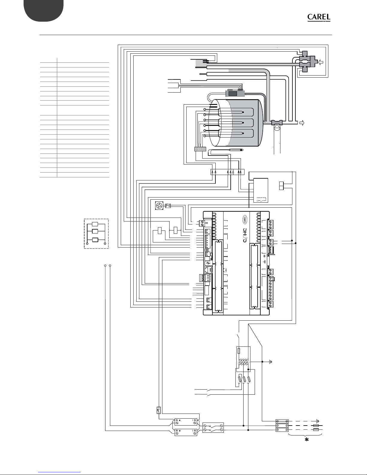
68
X1
X2
STEAM BOILER
LLC
LS
A
B
C
D
E
F
CS
ST
QC1
NTC
R1 R2
R3
PTC1
PTC2
PTC3
THP
M2 S1
S2
T1
T2
TO RD
- C
DP
FV
DT
J3.1 BLUE
J3.2 YELLOW
J3.4 RED
J3.5 PURPLE
E
F
1
2
R1
A
B
R2
C
D
R3
RD
K
TO LEVEL
SENSOR
FAN
FSB
+
-
M1
L1
L2
PE
K
POWER
SUPPLY
TO
DP
N.A. RD
TR
SSR2
SSR1
F4
F3
F2
F1
S1
1
2
BRIDGING CONNECTION
M2M9
12 1 123 123452121122123456
J17C
2 1
J17L J23 J24 J19J20J3 J16 M3 J18
2 1
J21
M8 M1 M5 M6M12
1 1234567821132 31221212
{
{
ALARM RELAY
C NC NO
GO
G
EXTERNAL SIGNALS
RS-
RS+K
M2
M1
0
24
J19.1
X1
BLUE
YELLOW
RED
PURPLE
CS
CS
LS
LS
NTC
NTC
RDA2
RDA1
KA2
KA1
EVF
EVF
ENG
“heaterSteam” +0300080EN - rel. 1.0 - 27.04.2016
* To be carried out by the installer
TB Terminal Board
THP Motor Protector
QC1 Fast coupling
K Contactor
LLC Level gauge
ST Sensor terminal block
F1 - F2 Primary circuit fuses
F3 Drain pump safety fuse
F4 Secondary circuit fuse
FV Infeed valve
PTC1…3
Temperature sensor
heater 1…3
TR Transformer
DP Drain pump
LS High level electrodes
CS Conductivity meter electrodes
MS Manual switch
R1…3 Electric heater 1…3
SSR1…2 Solid state relay
FSB Fan control board
FAN Fa n
RDT Drain tempering relay
DT Drain tempering valve
NTC Water temperature sensor
X1-X2 Power for fan blower (24Vac)
15.3 Wiring diagram UR006 single-phase 208 V / 230 V - version U
Fig. 15.c

69
X1
X2
TO RD
- C
STEAM BOILER
DP
FV
LLC
LS
E
F
A
B
C
D
CS
ST
QC1
NTC
R1 R2
R3
PTC1
PTC2
PTC3
THP
M1
M2 S1
S2
T1
T2
J3.1 BLUE
J3.2 YELLOW
J3.4 RED
J3.5 PURPLE
E
F
1
2
R1
A
B
R2
C
D
R3
K
TO LEVEL
SENSOR
FAN
FSB
+
-
L1
L2
PE
K
POWER
SUPPLY
TO
DP
N.A. RD
TR
SSR2
F4
F3
F2
F1
S1
1
2
BRIDGING CONNECTION
M2M9
12 1 123 123452121122123456
J17C
2 1
J17L J23 J24 J19J20J3 J16 M3 J18
2 1
J21
M8 M1 M5 M6M12
1 1234567821132 31221212
{
{
ALARM RELAY
C NC NO
GO
G
EXTERNAL SIGNALS
RS-
RS+K
M2
M1
0
24
J19.1
X1
BLUE
YELLOW
RED
PURPLE
CS
CS
LS
LS
NTC
NTC
RDA2
RDA1
KA2
KA1
EVF
EVF
RD
X3
X4
C
ENG
“heaterSteam” +0300080EN - rel. 1.0 - 27.04.2016
* To be carried out by the installer
TB Terminal Board
THP Motor Protector
QC1 Fast coupling
K Contactor
LLC Level gauge
ST Sensor terminal block
F1 - F2 Primary circuit fuses
F3 Drain pump safety fuse
F4 Secondary circuit fuse
FV Infeed valve
PTC1…3
Temperature sensor
heater 1…3
TR Transformer
DP Drain pump
LS High level electrodes
CS Conductivity meter electrodes
MS Manual switch
R1…3 Electrical resistor
SSR1…2 Solid state relay
FSB Fan control board
FAN Fa n
NTC Water temperature sensor
X1-X2 Power for fan blower (24Vac)
X3-X4
Power for drain tempering
kit (24Vac)
15.4 Wiring diagram UR006 single-phase 230 V - version 0
Fig. 15.d

70
X1
X2
RD
K
L1
L2
L3
K
SSR2
SSR3
2
3
1
TO
DP
N.A. RD
TR
TS
QC1
TO LEVEL
SENSOR
FAN
FSB
THP
+
-
M1
M2 S1
S2
T1
T2
S1
LLC
LS
A
B
C
D
E
F
CS
ST
NTC
R1 R2
R3
PTC1
PTC2
PTC3
DP
FV
DT
SSR1
STEAM BOILER
R1
R2
R3
1
2
3
A
C
E
B
D
F
R1
R2
R3
1
2
3
A
C
E
B
D
F
208V - 230V 3F
400V - 460V - 575V 3F
J3.1 BLUE
J3.2 YELLOW
J3.4 RED
J3.5 PURPLE
TO RD
- C
F4
F3
F2
F1
POWER SUPPLY
PE
M2M9
12 1 123 123452121122123456
J17C
2 1
J17L J23 J24 J19J20J3 J16 M3 J18
2 1
J21
M8 M1 M5 M6M12
1 1234567821132 31221212
{
EXTERNAL SIGNALS
{
ALARM RELAY
C NC NO
GO
G
1
BRIDGING CONNECTION
2
3
0
RS-
RS+K
M2
M1
EVF
EVF
KA1
KA2
RDA1
RDA2
24
J19.1
X1
CS
CS
LS
LS
NTC
NTC
BLUE
YELLOW
RED
PURPLE
ENG
“heaterSteam” +0300080EN - rel. 1.0 - 27.04.2016
* To be carried out by the installer
TB Terminal Board
THP Motor Protector
QC1 Fast coupling
K CONTACTOR
LLC Level gauge
ST Sensor terminal block
F1 - F2 Primary circuit fuses
F3 Drain pump safety fuse
F4 Secondary circuit fuse
FV Infeed valve
PTC1…3
Temperature sensor
heater 1…3
TR Transformer
DP Drain pump
LS High level electrodes
CS Conductivity meter electrodes
MS Manual switch
R1…3 Electric heater 1…3
SSR1…3 Solid state relay 1…3
FSB Fan control board
FAN Fa n
RDT Drain tempering relay
DT Drain tempering valve
NTC Water temperature sensor
X1-X2 Power for fan blower (24Vac)
15.5 Wiring diagram UR006-UR010-UR013 three-phase (208-230-400-460-575 V) - version U
Fig. 15.e

71
X1
X2
RD
K
L1
L2
L3
K
2
3
1
TO
DP
N.A. RD
TR
TS
QC1
TO LEVEL
SENSOR
FAN
FSB
THP
+
-
M1
M2 S1
S2
T1
T2
S1
LLC
LS
A
B
C
D
E
F
CS
ST
NTC
R1 R2
R3
PTC1
PTC2
PTC3
DP
FV
STEAM BOILER
R1
R2
R3
1
2
3
A
C
E
B
D
F
R1
R2
R3
1
2
3
A
C
E
B
D
F
230V 3F
400V - 460V 3F
J3.1 BLUE
J3.2 YELLOW
J3.4 RED
J3.5 PURPLE
TO RD
- C
F4
F3
F2
F1
POWER SUPPLY
PE
M2M9
12 1 123 123452121122123456
J17C
2 1
J17L J23 J24 J19J20J3 J16 M3 J18
2 1
J21
M8 M1 M5 M6M12
1 1234567821132 31221212
{
EXTERNAL SIGNALS
{
ALARM RELAY
C NC NO
GO
G
1
BRIDGING CONNECTION
2
3
0
RS-
RS+K
M2
M1
EVF
EVF
KA1
KA2
RDA1
RDA2
24
J19.1
X1
CS
CS
LS
LS
NTC
NTC
BLUE
YELLOW
RED
PURPLE
X3
X4
C
SSR1
SSR2
ENG
“heaterSteam” +0300080EN - rel. 1.0 - 27.04.2016
* To be carried out by the installer
TB Terminal Board
THP Motor Protector
QC1 Fast coupling
K CONTACTOR
LLC Level gauge
ST Sensor terminal block
F1 - F2 Primary circuit fuses
F3 Drain pump safety fuse
F4 Secondary circuit fuse
FV Infeed valve
PTC1…3
Temperature sensor
heater 1…3
TR Transformer
DP Drain pump
LS High level electrodes
CS
Conductivity meter elec-
trodes
MS Manual switch
R1…3 Electric heater 1…3
SSR1…2 Solid state relay 1…2
FSB Fan control board
FAN Fan
NTC Water temperature sensor
X1-X2 Power for fan blower (24Vac)
X3-X4
Power for drain tempering
kit (24Vac)
15.6 Wiring diagram UR006-UR010-UR013 three-phase (230-400-460 V) - version 0
Fig. 15.f

72
RD
K
FAN
F1
F2
F3
F4
TR
K
MS
TO DP
N.A. RD
QC1
THP
ST1
M1
M2 S1
S2
T1
T2
TO LEVEL
SENSOR
NTC
CS
LLC
FV
R4
R5
R6
PTC4
PTC5
PTC6
A
TO RD - C
LS
DP
S2
S1
R1
R2
R3
PTC1
PTC2
PTC3
ST2
F
E
D
C
B
PTC7
PTC8
PTC9
R9
R8
R7
ST3
G
H
I
L
M
N
O
P
Q
R
S
T
SSR2
SSR3
2
3
1
SSR1
DT
R1
R2
R3
1
2
3
A
C
E
B
D
F
575V 3F
R4
R5
R6
I
M
L
N
G
H
O
P
R
Q
S
T
R9
R8
R7
1
BRIDGING CONNECTION
2
3
M2M9
12 1 123 123452121122123456
J17C
2 1
J17L J23 J24 J19J20J3 J16 M3 J18
2 1
J21
M8 M1 M5 M6M12
1 1234567821132 31221212
{
{
GO
G
EXTERNAL SIGNALS
L1
L2
L3
POWER
SUPPLY
PE
J3.1 BLUE
J3.2 YELLOW
J3.4 RED
J3.5 PURPLE
BLUE
YELLOW
RED
PURPLE
CS
CS
LS
LS
NTC
NTC
RS-
RS+K
M2
M1
EVF
EVF
KA1
KA2
RDA1
RDA2
FAN
FAN
ALARM RELAY
C NC NO
EXTERNAL SIGNALS
ENG
“heaterSteam” +0300080EN - rel. 1.0 - 27.04.2016
* To be carried out by the installer
THP Motor Protector
QC1 Fast coupling
K CONTACTOR
LLC Level gauge
ST Sensor terminal block
F1 - F2 Primary circuit fuses
F3 Drain pump safety fuse
F4 Secondary circuit fuse
FV Infeed valve
PTC1…3 Temperature sensor heater 1…3
TR Transformer
DP Drain pump
LS High level electrodes
CS Conductivity meter electrodes
MS Manual switch
R1…3 Electric heater 1…3
SSR1…3 Solid state relay 1…3
FSB Fan control board
FAN Fa n
RDT Drain tempering relay
DT Drain tempering valve
NTC Water temperature sensor
S1 SSR thermal switch
S2 Heater thermal switch
15.7 Wiring diagram UR020 three-phase (208-230-400-460-575 V) - version U
Wiring diagram UR027 three-phase (400-460-575 V) - version U
Fig. 15.g

73
K
FAN
QC1
THP
ST
M1
M2 S1
S2
T1
T2
TO LEVEL
SENSOR
NTC
CS
LLC
FV
R1
R2
R3
PTC1
PTC2
PTC3
A
B
I
L
E
F
TO RD - C
LS
DP
S2
R1
R2
R3
1
2
3
A
E
I
B
F
L
400V - 460V 3F
J3.1 BLUE
J3.2 YELLOW
J3.4 RED
J3.5 PURPLE
BLUE
YELLOW
RED
PURPLE
CS
CS
LS
LS
NTC
NTC
M2M9
12 1 123 123452121122123456
J17C
2 1
J17L J23 J24 J19J20J3 J16 M3 J18
2 1
J21
M8 M1 M5 M6M12
11234567821132 31221212
{
{
ALARM RELAY
C NC NO
GO
G
EXTERNAL SIGNALS
RS-
RS+K
M2
M1
EVF
EVF
KA1
KA2
RDA1
RDA2
FAN
FAN
R1
R2
R3
1
2
3
A
E
I
B
F
L
230V 3F
RD
X3
X4
L1
L2
L3
K
2
3
1
N.A. RD
TR
MS
S1
F4
F3
F2
F1
POWER SUPPLY
PE
1
BRIDGING CONNECTION
2
3
C
SSR1
SSR2
TO DP
ENG
“heaterSteam” +0300080EN - rel. 1.0 - 27.04.2016
* To be carried out by the installer
THP Motor Protector
QC1 Fast coupling
K CONTACTOR
LLC Level gauge
ST Sensor terminal block
F1 - F2 Primary circuit fuses
F3 Drain pump safety fuse
F4 Secondary circuit fuse
FV Infeed valve
PTC1…3
Temperature sensor
heater 1…3
TR Transformer
DP Drain pump
LS High level electrodes
CS
Conductivity meter electrodes
MS Manual switch
R1…3 Electric heater 1…3
SSR1…3 Solid state relay 1…3
FAN F an
NTC Water temperature sensor
S1 SSR thermal switch
S2 Heater thermal switch
X3-X4
Power for drain tempering
kit (24Vac)
15.8 Wiring diagram UR020-UR027 three-phase (230-400-460 V) - version 0
Fig. 15.h

74
RD
K
FAN
F1
F2
F3
F4
TR
K
MS
TO DP
N.A. RD
QC1
THP
ST
M1
M2 S1
S2
T1
T2
TO LEVEL
SENSOR
NTC
CS
FV
R1
R2
R3
PTC1
PTC2
PTC3
A
B
I
L
E
F
LS
DP
S2
DT
F5
F6
F7
F8
F9
F10
SSR2
SSR3
2
3
1
SSR1
S1
1
2
3
L1
L2
L3
PE
TO RD - C
BLUE
YELLOW
RED
PURPLE
CS
CS
LS
LS
NTC
NTC
RS-
RS+K
M2
M1
EVF
EVF
KA1
KA2
RDA1
RDA2
FAN
FAN
R1
R2
R3
1
2
3
A
F
I
B
F
L
230V 3F
LLC
J3.1 BLUE
J3.2 YELLOW
J3.4 RED
J3.5 PURPLE
POWER SUPPLY
M2M9
12 1 123 123452121122123456
J17C
2 1
J17L J23 J24 J19J20J3 J16 M3 J18
2 1
J21
M8 M1 M5 M6M12
1 1234567821132 31221212
{
{
ALARM RELAY
C NC NO
GO
G
EXTERNAL SIGNALS
BRIDGING CONNECTION
ENG
“heaterSteam” +0300080EN - rel. 1.0 - 27.04.2016
* To be carried out by the installer
THP Motor Protector
QC1 Fast coupling
K CONTACTOR
LLC Level gauge
ST Sensor terminal block
F1 - F2 Primary circuit fuses
F3 Drain pump safety fuse
F4 Secondary circuit fuse
FV Infeed valve
PTC1…3 Temperature sensor heater 1…3
TR Transformer
DP Drain pump
LS High level electrodes
CS Conductivity meter electrodes
MS Manual switch
R1…3 Electric heater 1…3
SSR1…3 Solid state relay 1…3
FAN Fa n
RDT Drain tempering relay
DT Drain tempering valve
NTC Water temperature sensor
S1 SSR thermal switch
S2 Heater thermal switch
15.9 Wiring diagram UR027 three-phase (230 V) - version U
Fig. 15.i

75
RD
K
FAN
F1
F2
F3
F4
TR
L1
L2
L3
K
MS
TO DP
N.A. RD
QC1
THP
ST1
M1
M2 S1
S2
T1
T2
NTC
CS
LLC
FV
TO RD - C
DP
S2
ST2
S1
SSR2
SSR3
2
3
1
SSR1
DT
R1
R2
R3
1
2
3
A
C
E
B
D
F
R4
R5
R6
I
M
L
N
G
H
R1
R2
R3
1
2
3
A
C
E
B
D
F
R4
R5
R6
Q
S
R
T
O
P
()
J3.1 BLUE
J3.2 YELLOW
J3.4 RED
J3.5 PURPLE
575V 3F (UR053)
575V 3F (UR040) 400V - 460V
TO LEVEL
SENSOR
CS
CS
LS
LS
RS-
RS+K
M2
M1
EVF
EVF
KA1
KA2
RDA1
RDA2
FAN
FAN
NTC
NTC
BLUE
YELLOW
RED
PURPLE
PE
POWER SUPPLY
1
BRIDGING CONNECTION
2
3
M2M9
12 1 123 123452121122123456
J17C
2 1
J17L J23 J24 J19J20J3 J16 M3 J18
2 1
J21
M8 M1 M5 M6M12
11234567821132 31221212
{
EXTERNAL SIGNALS
{
ALARM RELAY
C NC NO
GO
G
LS
R4
R5
R6
R1
R2
R3
PTC1
PTC3
PTC2
PTC4
PTC5
PTC6
ENG
“heaterSteam” +0300080EN - rel. 1.0 - 27.04.2016
* To be carried out by the installer
THP Motor Protector
QC1 Fast coupling
K CONTACTOR
LLC Level gauge
ST1…2 Sensor terminal blocks
F1 - F2 Primary circuit fuses
F3 Drain pump safety fuse
F4 Secondary circuit fuse
FV Infeed valve
PTC1…6 Temperature sensor heater 1…6
TR Transformer
DP Drain pump
LS High level electrodes
CS Conductivity meter electrodes
MS Manual switch
R1…6 Electric heater 1…6
SSR1…3 Solid state relay 1…3
FAN Fa n
RDT Drain tempering relay
DT Drain tempering valve
NTC Water temperature sensor
S1 SSR thermal switch
S2 Heater thermal switch
15.10 Wiring diagram UR040 three-phase (400-460-575 V) - version U
Wiring diagram UR053 three-phase (575 V) - version U
Fig. 15.j

76
K
FAN
QC1
THP
ST1
M1
M2 S1
S2
T1
T2
NTC
CS
LLC
FV
R4
R5
R6
TO RD - C
LS
DP
S2
R1
R2
R3
PTC1
ST2
PTC3
PTC2
PTC4
PTC5
PTC6
J3.1 BLUE
J3.2 YELLOW
J3.4 RED
J3.5 PURPLE
TO LEVEL
SENSOR
CS
CS
LS
LS
RS-
RS+K
M2
M1
EVF
EVF
KA1
KA2
RDA1
RDA2
FAN
FAN
NTC
NTC
BLUE
YELLOW
RED
PURPLE
M2M9
1 2 1 123 1 2 3452121122123456
J17C
2 1
J17L J23 J24 J19J20J3 J16 M3 J18
2 1
J21
M8 M1 M5 M6M12
11234567821132 31221212
{
EXTERNAL SIGNALS
{
ALARM RELAY
C NC NO
GO
G
RD
X3
X4
L1
L2
L3
K
2
3
1
TO DP
N.A. RD
TR
MS
S1
F4
F3
F2
F1
POWER SUPPLY
PE
1
BRIDGING CONNECTION
2
3
C
SSR2
SSR1
4
5
6
R1
R2
R3
1
2
3
A
C
E
B
D
F
(UR040) 400V - 460V 3F
R1
R2
R3
4
5
6
G
I
M
H
L
N
R1
R2
R3
1
2
3
A
C
E
B
D
F
(UR053) 400V - 460V 3F
R1
R2
R3
4
5
6
O
Q
S
P
R
T
ENG
“heaterSteam” +0300080EN - rel. 1.0 - 27.04.2016
* To be carried out by the installer
THP Motor Protector
QC1 Fast coupling
K CONTACTOR
LLC Level gauge
ST1…2 Sensor terminal blocks
F1 - F2 Primary circuit fuses
F3 Drain pump safety fuse
F4 Secondary circuit fuse
FV Infeed valve
PTC1…6 Temperature sensor heater 1…6
TR Transformer
DP Drain pump
LS High level electrodes
CS Conductivity meter electrodes
MS Manual switch
R1…6 Electric heater 1…6
SSR1…3 Solid state relay 1…3
FAN Fa n
NTC Water temperature sensor
S1 SSR thermal switch
S2 Heater thermal switch
X3-X4 Power for drain tempering kit (24Vac)
15.11 Wiring diagram UR040-UR053 three-phase (400-460 V) - version 0
Fig. 15.k

77
400V - 460V 3F
RD
K
FAN
F1
F2
F3
F4
TR
L1
L2
L3
PE
K
MS
TO DP
N.A. RD
QC1
THP
ST1
M1
M2 S1
S2
T1
T2
TO LEVEL
SENSOR
R4
R5
R6
A
P
Q
R
S
T
TO RD - C
LS
DP
S2
R1
R2
R3
PTC1
B
C
D
E
F
O
ST2
PTC3
PTC2
PTC4
PTC5
PTC6
S1
SSR2
SSR3
SSR1
DT
F5
F6
F7
F8
F9
F10
1
BRIDGING CONNECTION
2
3
4
5
6
M2M9
12 1 123 123452121122123456
J17C
2 1
J17L J23 J24 J19J20J3 J16 M3 J18
2 1
J21
M8 M1 M5 M6M12
11234567821132 31221212
NTC
CS
LLC
FV
J3.1 BLUE
J3.2 YELLOW
J3.4 RED
J3.5 PURPLE
R1
R2
R3
1
2
3
A
C
E
B
D
F
R4
R5
R6
4
5
6
O
Q
S
P
R
T
CS
CS
LS
LS
RS-
RS+K
M2
M1
EVF
EVF
KA1
KA2
RDA1
RDA2
FAN
FAN
NTC
NTC
BLUE
YELLOW
RED
PURPLE
{
EXTERNAL SIGNALS
{
ALARM RELAY
C NC NO
GO
G
POWER SUPPLY
ENG
“heaterSteam” +0300080EN - rel. 1.0 - 27.04.2016
* To be carried out by the installer
QC1 Fast coupling
K CONTACTOR
LLC Level gauge
ST1…2 Sensor terminal blocks
F1 - F2 Primary circuit fuses
F3 Drain pump safety fuse
F4 Secondary circuit fuse
FV Infeed valve
PTC1…6 Temperature sensor heater 1…6
TR Transformer
DP Drain pump
LS High level electrodes
CS Conductivity meter electrodes
MS Manual switch
R1…6 Electric heater 1…6
SSR1…3 Solid state relay 1…3
FAN Fa n
RDT Drain tempering relay
DT Drain tempering valve
NTC Water temperature sensor
S1 SSR thermal switch
S2 Heater thermal switch
15.12 Wiring diagram UR053 three-phase (400-460 V) - version U
Fig. 15.l

78
RD
K
FAN
F1
F2
F3
F4
TR
K
MS
TO DP
N.A. RD
QC1
THP
ST1
M1
M2 S1
S2
T1
T2
TO LEVEL
SENSOR
NTC
CS
LLC
FV
R4
R5
R6
PTC4
PTC5
PTC6
A
TO RD - C
LS
DP
S2
S1
R1
R2
R3
PTC1
PTC2
PTC3
ST2
F
E
D
C
B
PTC7
PTC8
PTC9
R9
R8
R7
ST3
G
H
I
L
M
N
O
P
Q
R
S
T
SSR2
SSR3
2
3
1
SSR1
DT
R1
R2
R3
1
2
3
A
C
E
B
D
F
575V 3F
R4
R5
R6
I
M
L
N
G
H
O
P
R
Q
S
T
R9
R8
R7
1
BRIDGING CONNECTION
2
3
M2M9
12 1 123 123452121122123456
J17C
2 1
J17L J23 J24 J19J20J3 J16 M3 J18
2 1
J21
M8 M1 M5 M6M12
1 1234567821132 31221212
{
{
GO
G
EXTERNAL SIGNALS
L1
L2
L3
POWER
SUPPLY
PE
J3.1 BLUE
J3.2 YELLOW
J3.4 RED
J3.5 PURPLE
BLUE
YELLOW
RED
PURPLE
CS
CS
LS
LS
NTC
NTC
RS-
RS+K
M2
M1
EVF
EVF
KA1
KA2
RDA1
RDA2
FAN
FAN
ALARM RELAY
C NC NO
EXTERNAL SIGNALS
ENG
“heaterSteam” +0300080EN - rel. 1.0 - 27.04.2016
* To be carried out by the installer
QC1 Fast coupling
K CONTACTOR
LLC Level gauge
ST1…3 Sensor terminal blocks
F1 - F2 Primary circuit fuses
F3 Drain pump safety fuse
F4 Secondary circuit fuse
FV Infeed valve
PTC1…9 Temperature sensor heater 1…9
TR Transformer
DP Drain pump
LS High level electrodes
CS Conductivity meter electrodes
MS Manual switch
R1…9 Electric heater 1…9
SSR1…3 Solid state relay 1…3
FAN Fa n
RDT Drain tempering relay
DT Drain tempering valve
NTC Water temperature sensor
S1 SSR thermal switch
S2 Heater thermal switch
15.13 Wiring diagram UR060 three-phase (575 V) - version U
Fig. 15.m

79
400V - 460V 3F
RD
K
FAN
QC1
THP
ST1
M1
M2 S1
S2
T1
T2
TO LEVEL
SENSOR
R4
R5
R6
PTC4
PTC5
PTC6
A
TO RD - C
LS
DP
S2
R1
R2
R3
PTC1
PTC2
PTC3
ST2
F
E
D
C
B
PTC7
PTC8
PTC9
R9
R8
R7
ST3
G
H
I
L
M
N
O
P
Q
R
S
T
DT
R1
R2
R3
1
2
3
A
C
E
B
D
F
R4
R5
R6
I
M
L
N
G
H
R7
R8
R9
4
5
6
O
Q
S
P
R
T
M2M9
12 1 123 123452121122123456
J17C
2 1
J17L J23 J24 J19J20J3 J16 M3 J18
2 1
J21
M8 M1 M5 M6M12
1 1234567821132 31221212
{
{
NTC
CS
LLC
FV
J3.1 BLUE
J3.2 YELLOW
J3.4 RED
J3.5 PURPLE
CS
CS
LS
LS
RS-
RS+K
M2
M1
EVF
EVF
KA1
KA2
RDA1
RDA2
FAN
FAN
NTC
NTC
BLUE
YELLOW
RED
PURPLE
EXTERNAL SIGNALS
ALARM RELAY
C NC NO
GO
G
F1
F2
F3
F4
TR
L1
L2
L3
PE
K
MS
TO DP
N.A. RD
S1
SSR2
SSR3
SSR1
F5
F6
F7
F8
F9
F10
1
BRIDGING CONNECTION
2
3
4
5
6
POWER SUPPLY
ENG
“heaterSteam” +0300080EN - rel. 1.0 - 27.04.2016
* To be carried out by the installer
QC1 Fast coupling
K CONTACTOR
LLC Level gauge
ST1…3 Sensor terminal blocks
F1 - F2 Primary circuit fuses
F3 Drain pump safety fuse
F4 Secondary circuit fuse
FV Infeed valve
PTC1…9 Temperature sensor heater 1…9
TR Transformer
DP Drain pump
LS High level electrodes
CS Conductivity meter electrodes
MS Manual switch
R1…9 Electric heater 1…9
SSR1…2 Solid state relay 1…2
FAN Fa n
NTC Water temperature sensor
S1 SSR thermal switch
S2 Heater thermal switch
C Filter
15.14 Wiring diagram UR060 (400-460 V) - version U
Fig. 15.n
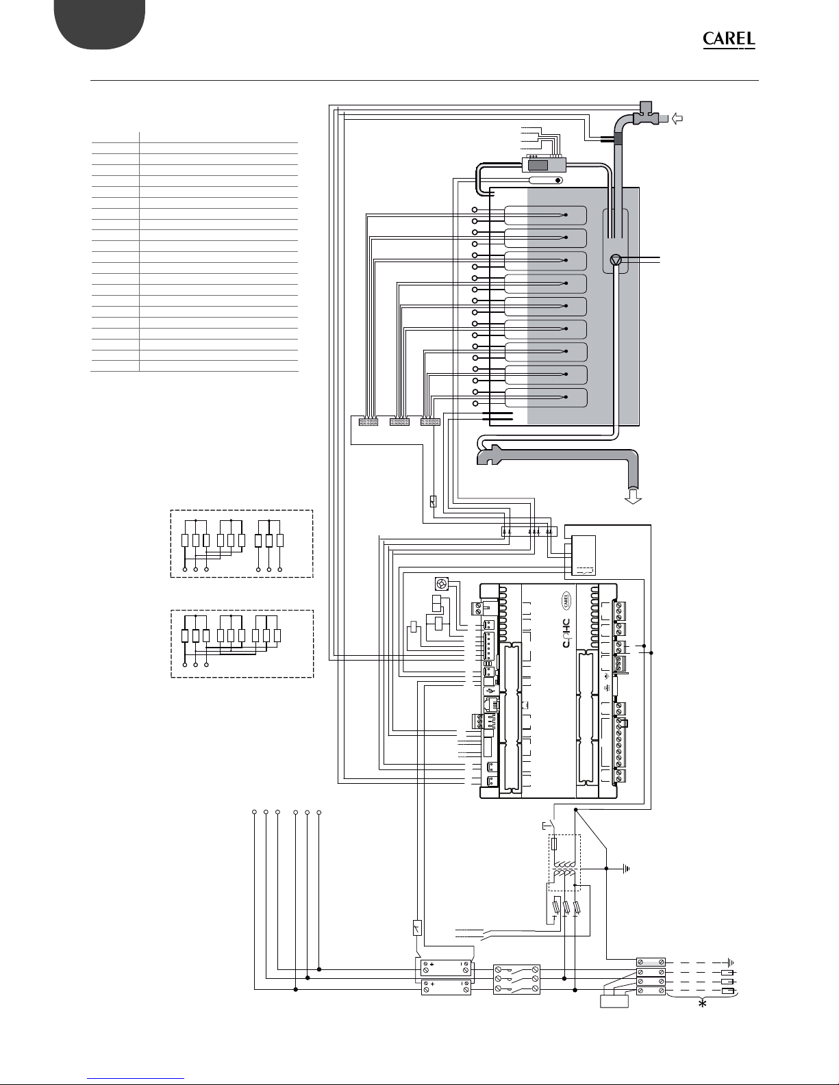
80
K
FAN
QC1
THP
ST1
M1
M2 S1
S2
T1
T2
TO LEVEL
SENSOR
NTC
CS
LLC
FV
R4
R5
R6
PTC4
PTC5
PTC6
A
TO RD - C
LS
DP
S2
R1
R2
R3
PTC1
PTC2
PTC3
ST2
F
E
D
C
B
PTC7
PTC8
PTC9
R9
R8
R7
ST3
G
H
I
L
M
N
O
P
Q
R
S
T
M2M9
12 1 123 123452121122123456
J17C
2 1
J17L J23 J24 J19J20J3 J16 M3 J18
2 1
J21
M8 M1 M5 M6M12
1 1234567821132 31221212
{
{
J3.1 BLUE
J3.2 YELLOW
J3.4 RED
J3.5 PURPLE
CS
CS
LS
LS
RS-
RS+K
M2
M1
EVF
EVF
KA1
KA2
RDA1
RDA2
FAN
FAN
NTC
NTC
BLUE
YELLOW
RED
PURPLE
EXTERNAL SIGNALS
ALARM RELAY
C NC NO
GO
G
L1
L2
L3
K
2
3
1
TO DP
N.A. RD
TR
MS
S1
F4
F3
F2
F1
POWER SUPPLY
PE
BRIDGING CONNECTION
C
SSR2
SSR1
RD
X3
X4
1
2
3
4
5
6
R1
R2
R3
1
2
3
A
C
E
B
D
F
(UR80) 400V - 460V 3F
R4
R5
R6
I
M
L
N
G
H
R7
R8
R9
4
5
6
O
Q
S
P
R
T
R1
R2
R3
1
2
3
A
C
E
B
D
F
R4
R5
R6
I
M
L
N
G
H
O
P
R
Q
S
T
R9
R8
R7
(UR60) 400V - 460V 3F
ENG
“heaterSteam” +0300080EN - rel. 1.0 - 27.04.2016
* To be carried out by the installer
K CONTACTOR
LLC Level gauge
ST1…3 Sensor terminal blocks
F1 - F2 Primary circuit fuses
F3 Drain pump safety fuse
F4 Secondary circuit fuse
FV Infeed valve
PTC1…9 Temperature sensor heater 1…9
TR Transformer
DP Drain pump
LS High level electrodes
CS Conductivity meter electrodes
MS Manual switch
R1…9 Electric heater 1…9
SSR1…3 Solid state relay 1…3
FAN Fa n
RDT Drain tempering relay
DT Drain tempering valve
NTC Water temperature sensor
S1 SSR thermal switch
S2 Heater thermal switch
X3-X4 Power for drain tempering kit (24Vac)
15.15 Wiring diagram UR060-UR080 three-phase (400-460 V) - version 0
Fig. 15.o

81
400V - 460V - 575V 3F
RD
K
FAN
QC1
THP
ST1
M1
M2 S1
S2
T1
T2
TO LEVEL
SENSOR
NTC
CS
LLC
FV
R4
R5
R6
PTC4
PTC5
PTC6
A
TO RD - C
LS
DP
S2
R1
R2
R3
PTC1
PTC2
PTC3
ST2
F
E
D
C
B
PTC7
PTC8
PTC9
R9
R8
R7
ST3
G
H
I
L
M
N
O
P
Q
R
S
T
DT
R1
R2
R3
1
2
3
A
C
E
B
D
F
R4
R5
R6
4
5
6
G
I
M
H
L
N
R7
R8
R9
7
8
9
O
Q
S
P
R
T
M2M9
12 1 123 123452121122123456
J17C
2 1
J17L J23 J24 J19J20J3 J16 M3 J18
2 1
J21
M8 M1 M5 M6M12
1 1234567821132 31221212
{
{
J3.1 BLUE
J3.2 YELLOW
J3.4 RED
J3.5 PURPLE
F1
F2
F3
F4
TR
L1
L2
L3
PE
K
MS
TO DP
N.A. RD
S1
SSR2
SSR3
SSR1
BRIDGING CONNECTION
POWER SUPPLY
CS
CS
LS
LS
RS-
RS+K
M2
M1
EVF
EVF
KA1
KA2
RDA1
RDA2
FAN
FAN
NTC
NTC
BLUE
YELLOW
RED
PURPLE
EXTERNAL SIGNALS
ALARM RELAY
C NC NO
GO
G
F5
F6
F7
F8
F9
F10
F11
F12
F13
1
2
3
4
5
6
7
8
9
ENG
“heaterSteam” +0300080EN - rel. 1.0 - 27.04.2016
* To be carried out by the installer
QC1 Fast coupling
K CONTACTOR
LLC Level gauge
ST1…3 Sensor terminal blocks
F1 - F2 Primary circuit fuses
F3 Drain pump safety fuse
F4 Secondary circuit fuse
FV Infeed valve
PTC1…9 Temperature sensor heater 1…9
TR Transformer
DP Drain pump
LS High level electrodes
CS Conductivity meter electrodes
MS Manual switch
R1…9 Electric heater 1…9
SSR1…2 Solid state relay 1…2
FAN Fa n
NTC Water temperature sensor
S1 SSR thermal switch
S2 Heater thermal switch
C Filter
15.16 Wiring diagram UR080 three-phase (400-460-575 V) - version U
Fig. 15.p

82
ENG
“heaterSteam” +0300080EN - rel. 1.0 - 27.04.2016
16. GENERAL FEATURES AND MODELS
16.1 heaterSteam models and electrical
features
The table below contains the electrical data regarding the power supply
voltages of the various models and the functional characteristics of each.
Note that some models may be powered at diff erent voltages, obviously
with diff erent consumption and steam output.
Stand.
mod.
Output
(2-4)
(kg/h) (lbs/hr)
Power
(2)
(KW)
Code
Voltage
(1)
(@50/60 Hz)
Elements
(n° x W)
Type of
connection
Current
(A)
Cable sect
(3)
(mm
2
)
Fuse-line (A/
type)
Boiler connection diagram
(5)
Wiring diagram
(5)
Unit
URxxxxxx03
Unit
URxxxxxxU3
Unit
URxxxxxx03
Unit
URxxxxxxU3
UR002
2.0 (4.4) 2.0 U 208 1 x 2012 – 9.7 2.5 10 / rapido - Fig. 16a - Fig. 15.a
2.0 (4.4) 2.0 D 230 1 x 1952 – 8.5 2.5 10 / rapido Fig. 16a Fig. 16a Fig. 15.b Fig. 15.a
UR004
4.0 (8.8) 3.6 U 208 1 x 3605 – 17.3 2.5 25 / rapido - Fig. 16a - Fig. 15.a
4.0 (8.8) 3.3 D 230 1 x 3306 – 14.4 2.5 20 / rapido Fig. 16a Fig. 16a Fig. 15.b Fig. 15.a
UR006
6.0 (13.2) 4.8 U 208 3 x 1597 – 23 6 32 / rapido - Fig. 16b - Fig. 15.c
6.0 (13.2) 4.7 D 230 3 x 1555 – 20.3 6 25 / rapido Fig. 16b Fig. 16b Fig. 15.d Fig. 15.c
6.0 (13.2) 4.8 W 208 3 x 1597 ∆ 3 x 13.3 2.5 16 / rapido - Fig. 16d - Fig. 15.e
6.0 (13.2) 4.7 K 230 3 x 1555 ∆ 3 x 11.7 2.5 16 / rapido Fig. 16d Fig. 16d Fig. 15.f Fig. 15.e
6.0 (13.2) 4.7 L 400 3 x 1568 Y 3 x 6.8 2.5 10 / rapido Fig. 16c Fig. 16c Fig. 15.f Fig. 15.e
UR010
10.0 (22) 8.1 W 208 3 x 2703 ∆ 3 x 22.5 6 32 / rapido - Fig. 16d - Fig. 15.e
10.0 (22) 7.4 K 230 3 x 2460 ∆ 3 x 18.5 6 25 / rapido Fig. 16d Fig. 16d Fig. 15.f Fig. 15.e
10.0 (22) 7.4 L 400 3 x 2480 Y 3 x 10.7 2.5 16 / rapido Fig. 16c Fig. 16c Fig. 15.f Fig. 15.e
10.0 (22) 7.8 M 460 3 x 2603 Y 3 x 9.8 2.5 16 / rapido Fig. 16c Fig. 16c Fig. 15.f Fig. 15.e
UR013
13.0 (28.6) 9.9 K 230 3 x 3306 ∆ 3 x 25 6 32 / rapido Fig. 16d Fig. 16d Fig. 15.f Fig. 15.e
13.0 (28.6) 10.0 L 400 3 x 3333 Y 3 x 14.4 2.5 20 / rapido Fig. 16c Fig. 16c Fig. 15.f Fig. 15.e
13.0 (28.6) 9.8 M 460 3 x 3280 Y 3 x 12.4 2.5 16 / rapido Fig. 16c Fig. 16c Fig. 15.f Fig. 15.e
13.0 (28.6) 9.7 N 575 3 x 3240 Y 3 x 9.8 2.5 16 / rapido - Fig. 16c - Fig. 15.e
UR020
20.0 (44) 16.2 W 208 3 x 5407 ∆ 3 x 45.0 16 60 / rapido - Fig. 16f - Fig. 15.g
20.0 (44) 15.1 K 230 3 x 5038 ∆ 3 x 37.9 16 60 / rapido Fig. 16f Fig. 16f Fig. 15.h Fig. 15.g
20.0 (44) 15.2 L 400 3 x 5079 Y 3 x 22.0 6 32 / rapido Fig. 16e Fig. 16e Fig. 15.h Fig. 15.g
20.0 (44) 15.1 M 460 3 x 5022 Y 3 x 18.9 6 25 / rapido Fig. 16e Fig. 16e Fig. 15.h Fig. 15.g
20.0 (44) 15.0 N 575 3 x 5008 Y 3 x 15.1 6 20 / rapido - Fig. 16e - Fig. 15.g
UR027
27.0 (59.5) 19.8 K 230 3 x 6612 ∆ 3 x 49.8 16 60 / rapido Fig. 16f Fig. 16f Fig. 15.h Fig. 15.i
27.0 (59.5) 20.0 L 400 3 x 6666 Y 3 x 28.9 10 50 / rapido Fig. 16e Fig. 16e Fig. 15.h Fig. 15.g
27.0 (59.5) 20.2 M 460 3 x 6717 Y 3 x 25.3 6 32 / rapido Fig. 16e Fig. 16e Fig. 15.h Fig. 15.g
27.0 (59.5) 19.8 N 575 3 x 6599 Y 3 x 19.9 6 25 / rapido - Fig. 16e - Fig. 15.g
UR040
40.0 (88) 30.5 L 400 6 x 5079 Y 3 x 44.0 16 50 / rapido Fig. 16g Fig. 16h Fig. 15.k Fig. 15.j
40.0 (88) 30.1 M 460 6 x 5022 Y 3 x 37.8 16 50 / rapido Fig. 16g Fig. 16h Fig. 15.k Fig. 15.j
40.0
(88) 30.0 N 575 6 x 5008 Y 3 x 30.2 10 50 / rapido - Fig. 16h - Fig. 15.j
UR053
53.0 (117) 40.0 L 400 6 x 6666 Y 3 x 57.7 25 80 / rapido Fig. 16i Fig. 16i Fig. 15.k Fig. 15.l
53.0 (117) 40.3 M 460 6 x 6717 Y 3 x 50.6 16 60 / rapido Fig. 16i Fig. 16i Fig. 15.k Fig. 15.l
53.0 (117) 39.6 N 575 6 x 6599 Y 3 x 39.8 16 60 / rapido - Fig. 16j - Fig. 15.j
UR060
60.0 (132) 45.7 L 400 9 x 5079 Y 3 x 66 25 80 / rapido Fig. 16k Fig. 16l Fig. 15.o Fig. 15.n
60.0 (132) 45.2 M 460 9 x 5022 Y 3 x 56.7 25 80 / rapido Fig. 16k Fig. 16l Fig. 15.o Fig. 15.n
60.0 (132) 45.1 N 575 9 x 5008 Y 3 x 45.3 16 50 / rapido - Fig. 16k - Fig. 15.m
UR080
80.0 (176) 60.0 L 400 9 x 6666 Y 3 x 86.6 50 125 / rapido Fig. 16l Fig. 16m Fig. 15.o Fig. 15.p
80.0 (176) 60.5 M 460 9 x 6717 Y 3 x 75.9 35 100 / rapido Fig. 16l Fig. 16m Fig. 15.o Fig. 15.p
80.0 (176) 59.4 N 575 9 x 6599 Y 3 x 59.6 25 80 / rapido - Fig. 16m - Fig. 15.p
Tab. 16.a
(1) tolerance allowed on rated mains voltage: -15%, +10%;
(2) tolerance on rated values: +5%, -10% (EN 60335-1);
(3) recommended values; referred to the laying of the cable in closed PVC or
rubber raceways with a length of 20 m (65.6 ft); the standards in force must in any
case be followed;
(4) instant max nominal steam output: the average steam production may be
infl uenced by external factors such as: room temperature, water quality, steam
distribution system;
(5) please refer to the wiring diagrams
The data are not absolute and may not comply with the local standards,
which should prevail.

83
ENG
“heaterSteam” +0300080EN - rel. 1.0 - 27.04.2016
16.2 Electrical connection of boiler heaters
The cable end should be coupled to the top nut applying a torque equal
to 3 N · m.
Single-phase
2-4 kg/h 208-230 V
Single-phase
6 kg/h 208-230 V
Three-phase - STAR
6 kg/h 400 V
10 kg/h 400-460 V
13 kg/h 400-460-575 V
Three-phase - TRIANGLE
6 kg/h 208-230 V
10 kg/h 208-230 V
13 kg/h 230 V
E
2
1
F
A
B
C
D
E
2
1
F
A
B
C
D
E
F
2
3
2
3
1
A
B
C
D
E
F
Fig. 16.a Fig. 16.b Fig. 16.c Fig. 16.d
Three-phase - STAR
20-27 kg/h 400-460-575 V
Three-phase - STAR
53 kg/h 400-460 V
Three-phase - STAR
53 kg/h 575 V
g
1
2
3
AB
EF
IL
1
2
3
45 6
AB
CD
EF
OP
QR
ST
1
2
3
AB
CD
EF
OP
QR
ST
Fig. 16.e Fig. 16.f Fig. 16.g
Three-phase - TRIANGLE
20-27 kg/h 208-230 V
Three-phase - STAR
60 kg/h 460 V
80 kg/h 400 V
Three-phase - STAR
60 kg/h 400-575V
1
2
3
AB
EF
IL
1
2
3
45 6
AB
CD
EF
GH
IL
MN
OP
QR
ST
1
2
3
AB
CD
EF
GH
IL
MN
OP
QR
ST
Fig. 16.h Fig. 16.i Fig. 16.j
Three-phase - STAR
40 kg/h 400 V
Three-phase - STAR
40 kg/h 460-575 V
Three-phase - STAR
80 kg/h 460-575 V
g
1
2
3
45 6
AB
CD
EF
GH
IL
MN
1
2
3
AB
CD
EF
GH
IL
MN
1
2
3
78 9 45 6
AB
CD
EF
GH
IL
MN
OP
QR
ST
Fig. 16.k Fig. 16.l Fig. 16.m
Key window
1-2-3-4 - 5-6-7-8-9 three-phase power supply terminals
1-2 single-phase power supply terminals

84
ENG
“heaterSteam” +0300080EN - rel. 1.0 - 27.04.2016
16.3 Technical features
model
UR002 UR004 UR006 UR010 UR013 UR020 UR027 UR040 UR053 UR060 UR080
Number of heaters 1 1 333666699
steam
Connection Ø mm (in) 30 (1.2) 40 (1.6) 2 x 40 (2x1.6)
delivery pressure limits Pa (PSI) 0…1500 (0...0,218) 0...2000 (0...0.290)
supply water
connection 3/4” G
temperature limits °C (°F) 1...40 (33.8...104)
pressure limits (MPa) 0.1...0.8 (1...8 bar)
hardness limits (°fH) ≤ 40
instant fl ow rate (l/min - Gallon/min) 1.1 1.1 1.1 1.1 1.1 4 4 4 10 10 10
drain water
Connection Ø mm (in) 40 (1.6) 50 (2)
typical temperature °C (°F) ≤100
instant fl ow rate (l/min - Gallon/min) 5 (50 Hz) - 9 (60 Hz) (1.3 - 2.3) 17.5 (50 Hz) - 24.3 (60 Hz) (4.6 - 6.4)
drain tempering instant fl ow rate (l/min - Gallon/min)* 23 (60Hz) (6) 54,3 (60Hz) (14.3)
* where needed
environmental conditions
room operating temperature °C (°F) 1...40 (33.9...104)
room operating humidity (% rH) 10...60
storage temperature °C (°F) -10...70 (33.8...158)
storage humidity (% rH) 5…95
protection rating IP20
system
type c.pHC
voltage / auxiliary frequency (V / Hz) 24 / 50/60
maximum auxiliary power (VA) 90
probe inputs (general characteristics)
selectable input signal: 0…1 Vdc, 0…10 Vdc, 2…10 Vdc, 0…20 mA, 4…20 mA
input impedance: 60 kΩ with signals: 0…1 Vdc, 0…10 Vdc, 2…10 Vdc
50 Ω with signals: 0…20 mA, 4…20 mA
power supply for active probes (general features)
24 Vdc (24 Vac rectifi ed), Imax= 250 mA
12 Vdc 5%, Imax= 50 mA
alarm relay outputs (general features)
250 V 2 A (2 A)
type of micro-switching action 1C
remote enabling input (general characteristics) dry contact; max resistance 50 Ω; Vmax=24 Vdc; Imax=5 mA
serial communication three-lead RS485 / Fieldbus / BMS
USB port USB type A
Ethernet port Ethernet
Tab. 16.l
16.4 Steam transport pipe models
humidifi er model: UR002 UR004 UR006 UR010 UR013 UR020 UR027 UR040 UR053 UR060 UR080
ø of steam outlet mm (in): 30 (1.2") 40 (1.6") 2x40 (1.6")
maximum capacity kg/h (lb/h): "2 (4.4)” “4 (8.8)” “6 (13.2)” “10 (22)” “13 (28.6)” “20 (44)” “27 (59.5)” “40 (88)” “53 (116.8)” “60 (132.2)” “80 (176.36)”
1312365AXX √ √ √ √ √
1312367AXX √√√ √ √ √
ONLY FOR NORTH AMERICA MARKET
SHOSE00030 √ √ √ √ √
SHOSE00040 √√√√ √ √
Tab. 16.m
16.5 Steam nozzle models
humidifi er model: UR002 UR004 UR006 UR010 UR013 UR020 UR027 UR040 UR053 UR060 UR080
ø of steam outlet mm (in): 30 (1.2”) 40 (1.6”) 2x40 (1.6”)
maximum capacity kg/h (lb/h):
2
(4.4)4 (8.8)6 (13.2)
10
(22)
13
(28.6)
20
(44)
27
(59.5)
40
(88)
53
(116.8)
60
(132.2)
80
(176.36)
“inlet diameter
nozzle ø mm (in)”
maximum capacity
nozzle kg/h (lb/h)
code
30 (1.2”) 18 (39.7) SDPOEM0022 1 11111(2)*
30 (1.2”) “18 (39.7)
with hole of 30 (1.2”) SDPOEM0000 1 1 1111(2)* (4)* (4)* (4)*
Tab. 16.n
*: use Y-type CAREL kit code UEKY000000, inlet 40mm (1.6”)
and 2 outlets 30mm (1.2”)
**: use Y-type CAREL kit code UEKY40X400, inlet 40mm (1.6”)
and 2 outlets 40mm (1.6”)

85
ENG
“heaterSteam” +0300080EN - rel. 1.0 - 27.04.2016
16.6 Linear nozzle models and typical installations
humidifi er model: UR002 UR004 UR006 UR010 UR013 UR020 UR027 UR040 UR053 UR060 UR080
ø of steam outlet mm (in): 30 (1.2”) 40 (1.6”) 2x40 (1.6”)
maximum capacity kg/h (lb/h):
2
(4.4)4(8.8)6(13.2)10(22)
13
(28.6)
20
(44)
27
(59.5)
40
(88)
53
(116.8)
60
(132.2)
80
(176.36)
"nozzle steam
inlet ø mm (in)”
maximum nozzle
capacity kg/h
(lb/h)
length
of nozzle mm (in)
code
30 (1.2”) 5 (11) 350 (13.7) DP035D30R0 1 1
30 (1.2”) 8 (17.6) 450 (17.7) DP045D30R0 1 1 1
30 (1.2”) 12 (26.4) 600 (23.6) DP060D30R0 1 1 1 (2)*
30 (1.2”) 18 (39.6) 850 (33.5) DP085D30R0 1111(2)* (2)*
30 (1.2”) 18 (39.6) 1050 (41.3) DP105D30R0 1111(2)* (2)*
30 (1.2”) 18 (39.6) 1250 (49.2) DP125D30R0 1111(2)* (2)*
30 (1.2”) 18 (39.6) 1650 (65) DP165D30R0 1 1 (2)* (2)*
30 (1.2”) 15 (33) 300 (11.8) DP030D30RU 11111
30 (1.2”) 15 (33) 450 (17.7) DP045D30RU 11111(2)* (2)*
30 (1.2”) 15 (33) 600 (23.6) DP060D30RU 1111(2)* (2)*
40 (1.6”) 25 (55) 850 (33.5) DP085D40R0 1 1 (2)** (4)** (4)** (4)**
40 (1.6”) 35 (77) 1050 (41.3) DP105D40R0 1 1 (2)** 2 2 (4)**
40 (1.6”) 45 (99) 1250 (49.2) DP125D40R0 11122 2
40 (1.6”) 45 (99) 1650 (65) DP165D40R0 1122 2
40 (1.6”) 45 (99) 2050 (80.7) DP205D40R0 1 2 2 2
40 (1.6”) 45 (99) 600 (23.6) DP060D40RU 11122 2
Tab. 16.o
(*) use CAREL “Y” kit P/N UEKY000000, 40 mm (1.6”) inlet and 2 x 30 mm (1.2”) outlets
(**) use CAREL “Y” kit P/N UEKY40X400, 40 mm (1.6”) inlet and 2 x 40 mm (1.6”) outlets
For typical installations of linear distibutors see Fig. 8.a.
≥ 70 mm
min. 200 mm
1
(8”)
(2.7”)
1/3 H
H > 250 mm
2
(9.8”)
1/3 H
≥ 200 mm
H > 250 mm
3
(9.8”)
(8”)
1/5 H
2/5 H
≥ 200 mm
H > 350 mm
4
(8”)
(13.7”)
1/5 H
2/5 H
H > 400 mm
5
(15.7”)
1/7 H
2/7 H
2/7 H
H > 500 mm
6
(19.7”)
1/7 H
2/7 H
2/7 H
H > 600 mm
7
(23.6”)
min 200 mm
=
=
8
(8”)
H > 200 mm
=
=
1/2 H
9
(8”)
H > 300 mm
=
=
=
=
10
(11.8”)
H > 500 mm
=
1/3 H
1/3 H
=
11
(19.7”)
Fig. 16.n

86
ENG
“heaterSteam” +0300080EN - rel. 1.0 - 27.04.2016


CAREL INDUSTRIES HQs
Via dell’Industria, 11 - 35020 Brugine - Padova (Italy)
Tel. (+39) 0499 716611 - Fax (+39) 0499 716600
carel@carel.com - www.carel.com
Agenzia:
“heaterSteam” +0300080EN - rel. 1.0 - 27.04.2016
 Loading...