


+XPL'LVN
0DQXDOHG¶XVR
8VHUJXLGH


Contents
1 GENERAL FEATURES................................................................................................................................................1
1.1 Applications..................................................................................................................................................................1
1.2 Operation.......................................................................................................................................................................1
2 CODES............................................................................................................................................................................2
2.1 Centrifugal Humidifier..................................................................................................................................................2
2.2 Electrical panels............................................................................................................................................................2
2.3 Humidistat mounted in the HDE electric panel.............................................................................................................2
2.4 Accessories....................................................................................................................................................................2
2.5 Humidity Probes............................................................................................................................................................2
3 INSTALLATION...........................................................................................................................................................3
3.1 Mounting.......................................................................................................................................................................3
3.1.1 Hanging mounting................................................................................................................................................3
3.1.2 Wall mounting......................................................................................................................................................3
3.2 Hydraulic connections...................................................................................................................................................5
3.3 Setting humidifier capacity............................................................................................................................................5
3.4 Electrical connections ...................................................................................................................................................6
3.4.1 Connecting the motor fan of the humidifier..........................................................................................................6
3.4.2 External Connections............................................................................................................................................7
3.5 Electrical panel HDE05MP230 for the control of one HDU centrifu gal hu m idifier.............................................................8
3.5.1 Connections of the HDE05MP230 electrical panel to the HDU humidifier.......................................................8
3.5.2 Connection to the electrical power .......................................................................................................................8
3.5.3 Connecting the humidity probe (ASH1, ASH2, ASDC11, ASDC111, ASPC11, ASPC23,ASWH1,ASWC11,
ASWC111)....................................................................................................................................................................9
3.5.4 Alarm output.........................................................................................................................................................9
3.5.5 Remote ON/Off ....................................................................................................................................................9
3.6 Control panel HDE10MP230 for the control of two HDU centrifugal humidifiers connected in parallel ..................10
3.6.1 Connecting the HDE10MP230 electrical panel to the first HDU humidifier ....................................................10
3.6.2 Connecting the HDE10MP230 electrical panel to the second HDU humidifier................................................10
3.7 IRDRW4000 Humidistat inside the HDE electric panel.............................................................................................11
3.7.1 Setting the main parameters................................................................................................................................12
3.7.2 IRDRW4 Technical specifications....................................................................................................................13
4 HUMIDIFIER START-UP..........................................................................................................................................14
4.1 Start-up........................................................................................................................................................................14
4.2 Main operations...........................................................................................................................................................14
4.3 Warnings.....................................................................................................................................................................14
5 MAINTENANCE.........................................................................................................................................................15
5.1 Removing and reassembling the filter.........................................................................................................................15
5.2 Storage ........................................................................................................................................................................15
5.3 What to do before and after long periods of inactivity................................................................................................15
5.4 Disposal of the product ...............................................................................................................................................15
6 WARRANTY CONDITIONS.....................................................................................................................................16
7 TECHNICAL SPECIFICATIONS.............................................................................................................................16
7.1 Standard references ....................................................................................................................................................16
HumiDisk - user manual Rel. 1.2 del 18/03/99


GENERAL SAFETY PRECAUTIONS
IMPORTANT: Before operating your HumiDisk you are kindly requested to carefully
read all the instructions and safety precautions contained in this manual.
1 General Features
HumiDisk
The instrument can be supplied with normal water.
HDU05RM230
temperature falls below 0°C (see Operating conditions in the Technical specifications). Furthermore a drain valve
avoids the water becoming stagnant in the tank when the humidifier is OFF.
The centrifugal humidifier
(
HDU05RM230)
is provided with an electrical heater to avoid the water, inside the machine, chilling when the room
motor-fan with a plastic element for water suction;
water tank allowing the positioning of a drain valve below it;
230V normally-closed water fill valve, with a water level command switch;
230V normally-closed drain valve (it opens when the humidifier stops);
fill, drain and overflow fitting (rubber fitting between drain and overflow);
thermostated heating element (250W, 230V);
air filter;
brackets and eyelets for wall or hanging mounting;
terminal block support.
is an air humidifier, based on the principle o f atomizing water through centrifugal fo rce.
HumiDisk
consists of:
1.1 Applications
HumiDisk
cold rooms and storage facilities for fresh produce, where lack of humidity leads to loss of weight and
product deterioration;
printing facilities, where the correct level of humidity must be maintained in order to avoid variations
in paper size;
textile industries, where humidity maintenance is an important factor in the productive processes, and
the need to eliminate the heat produced by the looms is essential.
These are just some of the industries which benefit from the application of the centrifugal-disk humidifier.
is especially suitable for applications such as:
1.2 Operation
HumiDisk
HDE05MP230
drain valve when the motor-fan is OFF (there is no humidity request).
The fill valve operates according to an ON/OFF signal from a humidistat as well, and it is subj ected to the water level
command switch, while the heating element, subjected to the general switch, is always on.
It is possible to set the capacity of the atomized water (see 3.3 below and fig. 4).
Furthermore, it is possible to command two
Humidisk - user manual Rel. 1.2 del 18/03/99
operates according to a ON/OFF signal coming from a humidistat positioned on an electrical panel (code
). The humidistat enables the motor-fan when a humidity request comes; on the co ntrary it enables the
HumiDisks
in parallel using the dedicated electrical panel
HD10MP230
.
1

2 Codes
2.1 Centrifugal Humidifier
Description
HumiDisk HDU05RM230
Code
2.2 Electrical panels
Description Code
Electrical panel for one HumiDisk HDE05MP230
Electrical panel for two HumiDisks HDE10MP230
2.3 Humidistat mounted in the HDE electric panel
Description Code
IRDRW4: 2 x relays, Din rail mounting, 24, 230 Vac, buzzer, pre-set for serial connection
and remote-control
IRDRW4000
2.4 Accessories
Description Code
Remote control IRTRRU(*)000
IRDRSER: serial connection board IRDRSER000
(*) I = Italian; E = English; D = German; F = French; S = Spanish.
2.5 Humidity Probes
WALL probes “ASW”
Outputs Range Code
Humidity 10÷90%rH ASWH10000
DUCT probes “ASD”
Outputs Range Code
Humidity 10÷90%rH ASDH100000
Humidity 0÷100%rH ASDH200000
Humidisk - user manual Rel. 1.2 del 18/03/99
2

3 Installation
3.1 Mounting
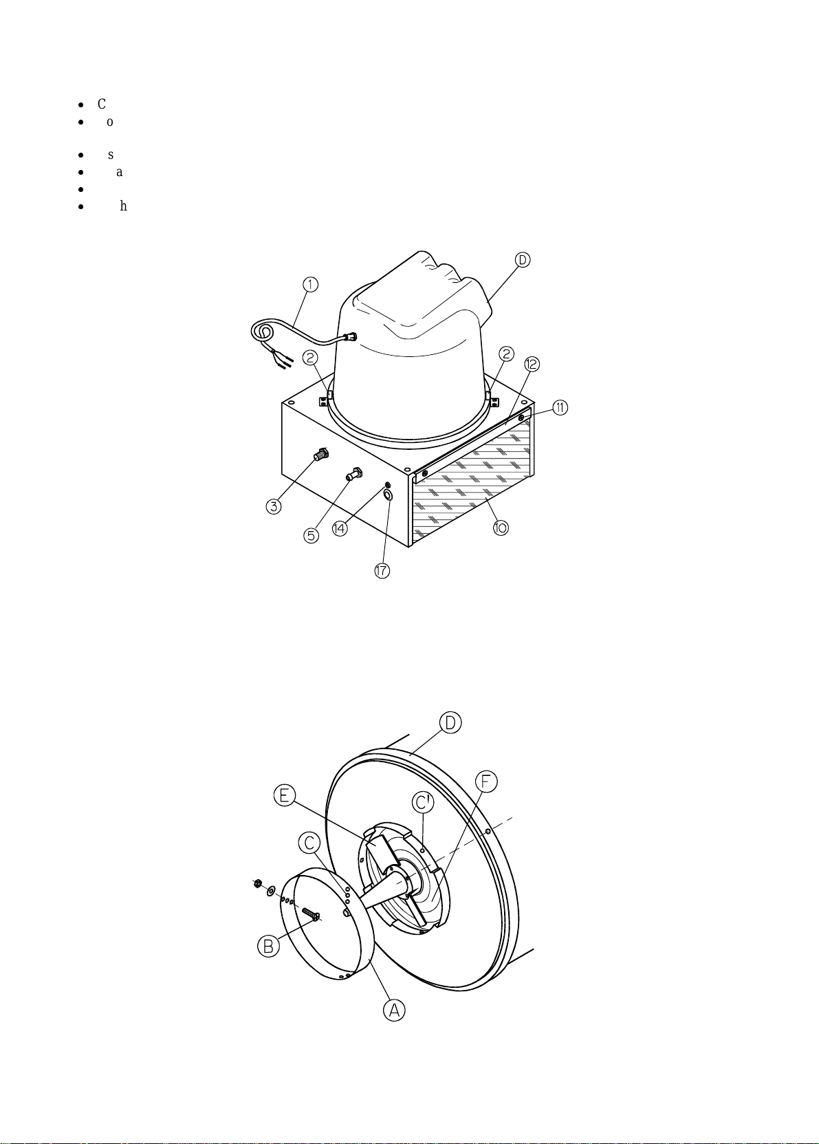
When you unpack the humidifier you will notice that it consists of two separate parts, different even from the electrical
point of view:
•
•
Before assembling the components decide in which direction you want to position the nozzles allowing the atomized
water to be spread in the environment. Finally fix the safety fixing brackets (see fig. 3).
3.1.1 Hanging mounting
To hang the appliance at the ceiling, connect it with chains or metal cables to the rings pr ovided (8), respecting the
minimum dimensions indicated in fig.1.
The minimum vertical distance from the ceiling must be 1000mm; the minimum horizontal distance from the wall
must be 114mm. Unit’s weight is 20Kg (fully loaded). The machine has to be installed in horizontal position.
Important: do not use hemp ropes or ropes made of any material that is sensitive to humidity.
3.1.2 Wall mounting
The minimum vertical distance from the ceiling must be 1000mm; the minimum horizontal distance from the wall
must be 114mm.
Use the special brackets (9) supplied with the appliance (fig.2). Fix the brackets (9) to the appliance using the screws
provided for the purpose.
Mark the holes on the wall where you want to install the appliance, respecting the distances between the holes on the
supporting brackets (9), so that, once it has been installed, the appliance is in horizontal position. The supporting
brackets are made in such a way that they keep the appliance at the right distance from the wall.
main motor-fan element
supporting structure (base).
Humidisk - user manual Rel. 1.2 del 18/03/99
3

Hanging mounting
Wall mounting
Fig. 1
Fig. 2
Humidisk - user manual Rel. 1.2 del 18/03/99
4
3.2 Hydraulic connections (Fig. 3)
Connect the water supply pipe using a 3/4" female coupling and the connector
Connect a rubber hose with 10mm diameter to the overflow connector
the closing float, allows the excess water to flow out
Install the appliance in the highest possible position, but keeping a distance of at least one metre from the ceiling
To avoid dripping, the spray of humidified air leaving the appliance must not strike any obstacle.
Turn the fairing (D) horizontally so that the flow comes out in the desired direction.
Fit the SAFETY fixing brackets (2) as shown in Figure 3.
(Fig.3).
(Ref. 3)
(Ref. 5)
Connecting the humidifier
.
which, in the event of malfunction of
(Fig.1, Fig.2)
.
Fig. 3
3.3 Setting humidifier capacity
In order to set the humidifying capacity follow these instructions:
•
unfasten the screws (B) under the fairing and slide the ring (A); the further the ring is pushed into the fairing (D), the
lower the humidifying capacity of the appliance is. The capacity ranges between 1.5 l/h (m in) and 5 l/h (m ax.);
•
fasten the ring in one of the three possible positions with the screws provided, matching the holes (C) in the ring (A)
with the holes (C') in the fairing.
Fig. 4
Humidisk - user manual Rel. 1.2 del 18/03/99
5

3.4 Electrical connections
3.4.1 Connecting the motor fan of the humidifier
Fig. 5
Fig. 6
Extract the air filter fixing screws (11) (fig.3).
Unscrew the screws that fasten the cap of the branch box.
Pass the power supply cable (1) of the humidifier through the fair-lead (14) and the cable-fastener (15) far
away from the resistor as showed in Figure 5.
Insert the yellow-green lead terminal of the cable from the fan motor into the earth terminal (8); the other two
terminals must be inserted into the terminals 4 and 5 on the terminal block of the humidifier.
Fasten the terminal screws and the cable-fastener stop-nut.
Humidisk - user manual Rel. 1.2 del 18/03/99
6

3.4.2 External Connections
Insert the inner plastic (13.5mm diameter) spiral-like sheath into the specific sheath-fastener (16) and clamp the
fastening ring nut. Then pass the sheath through the fair-lead (19) and connect it to the electrical system’s
prearranged branch box.
to avoid the water chilling inside the machine, it is necessary to constantly supply the heating resistor (17). The
Note:
safety thermostat (18) prevents the heating element from reaching excessive temperatures.
The humidistat, if present, will have to operate only the humidifier motor.
IMPORTANT:
2,5mm² maximum cross-section.
Connect the earth wire to terminal 9.
Connect the neutral wire to terminal 2 and the phase that is
Connect the phase controlled by the humidistat (if present) to terminal 3.
Important:
(e.g. fuses). The motor is provided with a thermal protection.
Once all the connections are set according to the instructions reported above, re-mount the branch box cap and fasten
the screws.
Re-mount the air filer.
when making electrical connections use insulated conductors with 1,5mm² minimum cross-section and
controlled by the humidistat, to terminal 1.
not
both the heating element and the motor must be protected against short-circuits by means of specific devices
Humidisk - user manual Rel. 1.2 del 18/03/99
7

3.5 Electrical panel HDE05MP230 for the control of one HDU centrifugal humidifier
Fig. 7
The wiring connections to be made on the terminal block of the HDE electrical panel concern connection to the HDU
humidifier, to power source, to humidity probe, to alarm output and remote On/Off.
IMPORTANT:
when mak ing electrical connection s us e insu lated conductors w ith 1.5m m ² m in im um cros s-s ection.
3.5.1 Connections of the HDE05MP230 electrical panel to the HDU humidifier
Access the branch box of the HDU humidifier removing the air filter (see 3.4.1 above).
Connect the terminal
the terminal
the terminal
the terminal
the terminal
of the electrical panel to the terminal 1 of the humidifier,
60
“ to the terminal 3
70
“ to the terminal 2 “
80
“ to the terminal 7
90
“ to the terminal 9
10
“
“
“
Humidisk - user manual Rel. 1.2 del 18/03/99
8

3.5.2 Connection to the electrical power
Connect
neutral wire
ground wire
phase wire
to the terminal F of the electrical panel,
to the terminal N “
to the terminal
PE.
“
3.5.3 Connecting the humidity probe (ASH1, ASH2, ASDC11, ASDC111, ASPC11,
ASPC23,ASWH1,ASWC11, ASWC111)
Connect the terminal 1 of the electrical panel to the terminal M (reference/ground) of the active humidity probe ,
the terminal 2 “ to the terminal
the terminal 3 “ to the terminal
If present, connect the screened shield of the probe to terminal 1.
(supply)
+(G)
(output of the probe)
out H
3.5.4 Alarm output
Three terminal blocks for alarms are available on the electrical panel: NC, C and NO (probe alarm, low humidity alarm
and high humidity alarm).
3.5.5 Remote ON/Off
Terminals 4 and 5 are available for remote On/Off (they are factory-bridged).
The bridge can be pulled out. It is possible to make the humidifier work by means of an external voltage-free contact to
be connected to terminals 4 & 5 after having removed the bridge.
Humidisk - user manual Rel. 1.2 del 18/03/99
9

3.6 Control panel HDE10MP230 for the control of two HDU centrifugal humidifiers
connected in parallel
Fig. 8
The wiring connections to be made on the terminal block of the HDE electrical panel concern connection to the first
humidifier, connection to the second humidifier, to power source, to humidity probe, to alarm output and to remote
On/Off.
Important: when making electrical connections use ins ulated conductors w ith 1.5mm² minimum cross -section.
3.6.1 Connecting the HDE10MP230 electrical panel to the first HDU humidifier
Connect the terminal
the terminal
the terminal
the terminal
the terminal
of the electrical panel to the terminal 1 of the humidifier,
60
“ to the terminal
70
“ to the terminal 2 “
80
“ to the terminal
90
“ to the terminal
10
3 “
7 “
9 “
3.6.2 Connecting the HDE10MP230 electrical panel to the second HDU humidifier
Connect the terminal
the terminal
the terminal
the terminal
the terminal
As for the other devices (power source, probe, remote On/Off, see 3.5 above).
of the electrical panel to the terminal 1 of the humidifier,
61
“ to the terminal
71
“ to the terminal 2 “
81
“ to the terminal
91
“ to the terminal
10
3 “
7 “
9 “
Humidisk - user manual Rel. 1.2 del 18/03/99
10

3.7 IRDRW4000 Humidistat inside the HDE electrical panel
Carel centrifugal humidifier, producing 5Kg/h of steam, can be managed by an electric panel (code
provided with ON/OFF microprocessor-based controller IRDRW4. The humidity value measured by the probe will be
constantly displayed on the LCD of the controller. In addition, it is possible to enhance the functions of the co ntroller
thanks to a remote ON/OFF command and an extra alarm output.
HDE05MP230
)
1.
2.
3.
4.
5.
6.
7.
displays the value of the probe connected. In the event of alarm condition, the probe value will be
LCD:
displayed alternatively to the code of the current alarm. While programming the instrument, the disp lay shows the
codes of the parameters and their values.
decimal LED indicator:
LED Reverse:
how many relays are energized in the “Reverse” mode. The LED blinks every 2 seconds.
LED Direct:
many relays are energized in the “Direct” mode. The LED blinks every 2 seconds.
displays and/or sets the Set-Point. If you hold it down together with
:
allowed to insert the password and to access the configuration parameters (“Cxx” parameters).
hold it down for 5 seconds to access the menu of the frequently used parameters (“Pxx”). When an off-
:
normal condition occurs, press it to silence the buzzer. It resets any alarm signal if pressed after the cause that
generated the alarm has disappeared.
increases the value of the Set-Point or any other selected parameter.
:
flashes when at least one relay ennergizes in the “Reverse” mode. The number of flashes indicates
flashes when at least one relay energizes in the “Direct” mode. The number of flashes indicates how
appears when the controlled variable is displayed with decimal point precision.
for 5 seconds, you will be
Fig. 9
8.
Humidisk - user manual Rel. 1.2 del 18/03/99
decreases the value of the Set-Point or any other selected parameter.
:
11

The diagram shows the operating modes of the controller.
Factory-set parameters
Parameter Code Set value
Set-Point St1 50
Differential P1 5.0
Neutral zone P3 0
Probe calibration P14 0.0
Low humidity alarm P25 0.0
High humidity alarm P26 99.9
Alarm differential P27 2.0
Delayed alarm P28 20
3.7.1 Setting the main parameters
SET-POINT (St1)
hold down
St1 appears on the display;
release
the SET 1 value flashes on the display;
press
press
Differential (P1)
hold down
“P1”, the first parameter, appears on the display;
press
the current value of P1 appears on the display;
press
press
press
for a few seconds;
;
/ to change its value;
to confirm the new St1 value and return to the main window.
for 5 seconds;
;
/ to change its value;
to confirm the new value;
to return to the main window.
Humidisk - user manual Rel. 1.2 del 18/03/99
12

Low humidity alarm P25, high humidity alarm P26, alarm differential P27, delayed alarm P28
hold down
the first parameter “P1” appears on the display;
for 5 seconds;
press
press
the display shows the current value of the parameter;
press
press
press
/ until you reach P25 (absolute value), P26, P27 or P28;
;
/ to change its value;
to confirm;
to return to the main window.
3.7.2 IRDRW4 Technical specifications
Power supply 24Vac ±10% , 230Vac ±10%
Power consumption 3VA
Operating range 0÷50°C
Resolution 0.1 from-9.9 to 99.9; 1 in the rest of the range
Control accuracy ±0.5% full scale
Storage conditions -10÷70°C, below 90% rH non-condensing
Operating conditions 0÷50°C, below 90% rH non-condensing
Mounting DIN guide
Case Plastic
Index of protection IP40 (panel mounting)
Connections Screw terminal blocks, cross section: 0.5mm² and max. 1.5mm²
Inputs (voltage probes) -0.4 ÷ +1Vdc
Probe supply output 10Vdc, I
Outputs 2 x SPDT relays: Vac
consumption = 2000VA, max. inrush current = 10A
Type of action-disconnection 1C (ECC EN 60730-1)
Insulation The low voltage parts come with main insulation with respect to
the very low voltage parts and a do uble insulation with respect to
the front panel
Environmental pollution Normal
Serial connection By means of IRDRSER board
max.
= 30mA
= 250V, max. power
max.
Important: cables should resist to maximum operating temperature, that is the maximum room temperature allowed
plus the controller self-heating that is 20°C, when all outputs are maximum loaded.
Humidisk - user manual Rel. 1.2 del 18/03/99
13

4 Humidifier start-up
4.1 Start-up
Before starting the humidifier, make sure that:
1. the humidifier is installed in horizontal position;
2. all pipes are correctly installed and connected;
3. all the other components are properly assembled and installed in the correct position;
4. then power the unit;
5. use normal water only.
Important: always turn Off the main switch of the humidifier before moving the unit or carrying out any
intervention on it.
4.2 Main operations
1. Supply the humidifier with water;
2. turn ON the humidifier;
3. the atomized water will be conveyed through flexible p ipes and will be spread in the environment by the air flow
produced by the built-in fan;
4. during the humidification process, the water level in the tank will be kept constant by the float switch and solenoid
valve;
5. should the water level fall below the safety level, the float switch and the relay will immediately interrupt the
humidification process.
4.3 Warnings
1. Make sure the humidifier produces and spreads atomized water in a regular and uniform way; during
humidification the water valve must be kept OPEN;
2. never remove the upper part of the humidifier during normal operation;
3. do not stop up the air suction or supply pipe.
Humidisk - user manual Rel. 1.2 del 18/03/99
14

5 Maintenance
Check periodically the air filter (10) and, if necessary, remove and clean it (fig.3). To remove the filter (10), see 5.1
below. The filter may be washed with water or cleaned with a vacuum cleaner.
Warning: do not use the appliance without the filter (10).
If you have to remove the fan ( E) and the di sk (F) in fig. 4, firs t mark bo th the d isk and the fa n with a marking pen so
that you can reassemble them exactly in the same position. The fan-disk unit has been balanced in the given position.
IMPORTANT:
if you have to change the power supply cable, please ask for an original one.
5.1 Removing and reassembling the filter
To remove the filter, unscrew the fixing screws on the bars (ref. 12, fig.3).
To reassemble the filter, first block one o f the ends with the bar using the screws provided. Then take the other end
of the filter and the second bar at the same time and place them in fixing position. Hold down the bar so that it
clamps the filter against the appliance, then fasten the two remaining screws.
5.2 Storage
Keep the appliance in a place where the temperature ranges between -10°C and +60°C.
When the appliance is still in its package, keep the box in an upright position.
Do not pile other heavy material on top of the box.
5.3 What to do before and after long periods of inactivity
Before:
Turn off the general switch of the electrical panel and turn off the water supply tap.
Check the water tank. It must be empty.
Cover the machine to protect it from dust.
After:
The fan must turn freely without friction (to check this, lift the top part of the machine (fig.4) and push the red fan
(E) with your hand so that it turns).
The switch level of the float in the water tank must be able to go up and down.
The machine must be correctly installed.
5.4 Disposal of the product
The product is essentially made of plastic and metal, both recyclable. Before disposing of the product it is better to
separate the plastic parts (cover, fan, blades, etc.) from the metal ones (motor, tank, etc.).
Humidisk - user manual Rel. 1.2 del 18/03/99
15

6 Warranty conditions
This instrument is covered by a 24-month guarantee against any fault of constructio n or of material. The warranty does
not cover damages due to transport, faulty maintenance, carelessness, improper use, misuse on the part of nonauthorized personnel or any other cause which does not depend on Carel.
During the 24-month warranty, Carel will replace or repair at no costs any components which might prove to be faulty.
All repairs will take place at Carel's premises. Carriage shall be to your charge.
7 Technical specifications
Power supply 230V, single phase, 50Hz
Rated power 0.49kW
Rated current 3A
External line fuse 5A, AM type
Air capacity 300 m3/h max.
Atomisation capability 1.5÷5l/h
Water supply pressure 30÷300kPa
Index of protection IPX4
Dry weight 18.3kg (fig. 1), hanging mounting
21.2kg (fig. 2), wall mounting
Tank capacity 2 litres
Operating conditions -2÷30°C, 0÷100%rH
7.1
Standards
In accordance with low voltage directive 73/23/EEC modified by 93/68/EEC; directive EMC 89/336/EEC on
electromagnetic compatibility and 89/392/EEC modified by 93/68/EEC; Standards EN 60034.
Carel reserves the right to modify the features of its products without prior notice.
Standard references
CEI EN 60204-1
on the safety of the appliance and its electrical components.
Humidisk - user manual Rel. 1.2 del 18/03/99
16


&$5(/VUO
Via dell’Industria, 11 - 35020 Brugine - Padova (Italy)
Tel. (+39) 049.9716611 Fax (+39) 049.9716600
http://www.carel.com
- e-mail: carel@carel.com
Agenzia / $JHQF\
Cod: +030221750 rel. 1.2 del 18/03/99
 Loading...