


FCM electronic regulator Cod. +302235300 - Rel. 2.0 del 30/11/98
1
Contents
1 Introduction........................................................................................................................................................................................ 2
1.1 General characteristics ...................................................................................................................................................................... 2
2 Codes of instruments and accessories................................................................................................................................................ 2
2.1 FCM* codes...................................................................................................................................................................................... 2
2.2 Accessories ....................................................................................................................................................................................... 2
3 Buttons and displayed indications.....................................................................................................................................................3
3.1 Front panel ........................................................................................................................................................................................ 3
4 Installation.......................................................................................................................................................................................... 4
4.1 Mounting the instrument ................................................................................................................................................................... 4
4.2 Electrical connections ........................................................................................................................................................................ 4
5 Functions............................................................................................................................................................................................ 5
5.1 Serial option...................................................................................................................................................................................... 5
6 Programming and configuring the FCM*......................................................................................................................................... 6
6.1 Standard configuration....................................................................................................................................................................... 6
6.2 Initialisation of FCM* instruments ....................................................................................................................................................6
6.3 Auxiliary functions............................................................................................................................................................................ 7
6.4 High and Low alarms (not available in slave mode)........................................................................................................................... 8
6.5 Defrosting (not available in SLAVE mode) ........................................................................................................................................ 8
6.6 Multifunction digital inputs............................................................................................................................................................... 9
6.7 Multi-function digital output............................................................................................................................................................ 10
6.8 Extra LED indicators ....................................................................................................................................................................... 10
7 Programming FCM controllers ....................................................................................................................................................... 11
7.1 Setting the set-point ("St" parameters)............................................................................................................................................. 11
7.2 Accessing "P" parameters................................................................................................................................................................ 11
7.3 Accessing "C" parameters................................................................................................................................................................ 11
7.4 Validity of the modifications............................................................................................................................................................ 12
7.5 Displaying the unit of measure ........................................................................................................................................................ 12
7.6 Setting min. and max. output values ................................................................................................................................................ 12
7.7 Factory-set parameters..................................................................................................................................................................... 13
7.8 Remote Control............................................................................................................................................................................... 13
7.9 Technical specifications................................................................................................................................................................... 13
7.10 Description of the keypad .............................................................................................................................................................. 13
7.11 Using the remote control................................................................................................................................................................ 14
7.12 Setting the access code .................................................................................................................................................................. 14
8 Description of the parameters.......................................................................................................................................................... 15
8.1 Parameters concerning the set-point................................................................................................................................................. 15
8.2 Parameters concerning the analogue output...................................................................................................................................... 16
8.3 Parameters concerning inputs .......................................................................................................................................................... 18
8.4 Alarm parameters............................................................................................................................................................................ 19
8.5 Parameters concerning digital inputs and output .............................................................................................................................. 20
8.6 Parameters concerning the unit of measure ...................................................................................................................................... 21
8.7 Parameters concerning defrost ......................................................................................................................................................... 23
8.8 Parameters concerning keypad and remote control ........................................................................................................................... 24
8.9 Parameters concerning serial connection.......................................................................................................................................... 25
9 Table of Parameters......................................................................................................................................................................... 27
10 Alarms ............................................................................................................................................................................................ 31
11 Technical specifications.................................................................................................................................................................. 32
12 Wiring diagram.............................................................................................................................................................................. 33
12.1 Terminal block.............................................................................................................................................................................. 33
12.2 Power supply:................................................................................................................................................................................ 33
12.3 Connecting probes......................................................................................................................................................................... 34
13 Dimensions...................................................................................................................................................................................... 35
FCM electronic regulator Cod. +302235300 - Rel. 2.0 del 30/11/98
2
1 Introduction
The electronic controls of FCM series have been designed to manage the main physical values (temperature, pressure, humidity) in airconditioning, refrigeration and heating units.
1.1 General characteristics
There are 3 models available, which differ according to the type of analogue input (probe).
Adaptability: continuous or On/Off-type regulatory controls.
Serial option: the FCM controls are designed to allow connection to supervisory or pLAN networks (local area networks made up of
pCO controllers).
Accessories: a serial interface board (FCSER00000) which is fitted inside the control and Infrared remote control for programming
functions is available on request.
Certification: CE mark, ISO 9001 certified design and production system.
Applications: although being designed for general use, the FCM series devices are particularly effective as condensation temperature
controls, as they control fan speed in condensation units.
In this situation, special devices are used to power the fans proportionally to the signal from the FCM control.
There is a variety of such power devices available (multi-step transformer, phase cut, frequency converter). CAREL, in particular, has
developed a family of phase cutting power devices, specially designed for this type of application. Ask Carel for further information.
2 Codes of instruments and accessories
2.1 FCM* codes
Model Code
2-input control for NTC probes FCM00NTC00
2-input control for probes with 0÷10 V voltage output
FCM0001000
2-input controller for probes with 0÷20 mA or 4÷20 mA current
output
FCM0002000
2.2 Accessories
Serial interface Code
Two-wires RS485 serial interface option FCSER00000
Infrared remote control
Language Code
ENGLISH IRTRFC0E00
Probes
Model Code
Carel NTC temperature probes NTC*
0÷25 bar pressure probes, 4÷20 mA output SPK2500000
0÷30 bar pressure probes, 4÷20 mA output SPK3000000
FCM electronic regulator Cod. +302235300 - Rel. 2.0 del 30/11/98
3
3 Buttons and displayed indications
3.1 Front panel
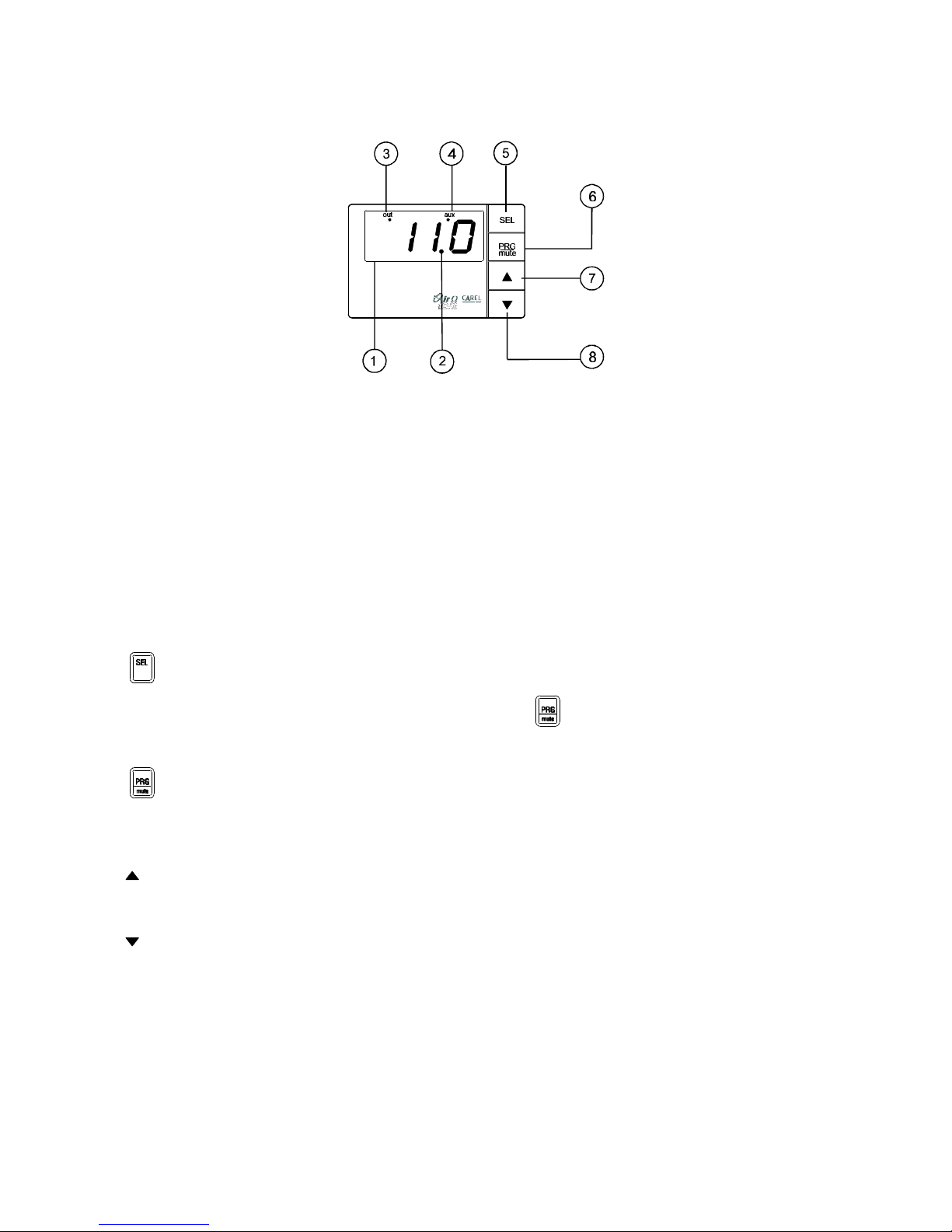
Fig. 1
1 - Display:
• it displays the value of the connected probes or the status of the control, as programmed (parameter C33);
• in the event of alarm, it displays the alarm code;
• during the programming it displays the parameter codes and their values.
2 - LED decimal:
• it turns on when the value being controlled is displayed with decimal point resolution.
3 - LED OUT:
• it turns on when the 0÷10 V output energises (output voltage different from 0 V);
• it flashes when the 0÷10 V output reaches its maximum programmed value.
4 - LED AUX:
• it turns on or flashes according to the selected operating mode.
5 - button:
• displays and/or sets the set-point; if pressed together with the PRG/mute button for 5 seconds, it allows the password to be
inserted and the configuration parameters to be accessed (parameters with code “Cxx” ).
6 - button:
• if pressed for 5 seconds, it allows the more frequently used parameters to be accessed (parameters with code “Pxx”);
• in the event of alarm it silences the buzzer; if pressed again, resets the alarm signal, as long as the cause of the alarm has been
removed.
7 - button:
• while being pressed it displays the value of probe 1;
• during the programming it moves to the next parameter or increases the value of the parameter.
8 - button:
• while being pressed it displays the value of probe 2;
• during the programming it moves back to the previous parameter or decreases the value of the parameter.

FCM electronic regulator Cod. +302235300 - Rel. 2.0 del 30/11/98
4
4 Installation
4.1 Mounting the instrument
1) Connect probes and power: probes can be placed up to 100 m distant from the controller provided that you use 1mm² cross-section,
possibly shielded, cables to increase immunity against noises.
2) Program the control following the instructions in the “Programming” section.
3) Connect the actuators: the actuators should only be connected after having programmed the control.
Note: the maximum load values for inputs and outputs should be respected, as indicated in the “Technical specifications”
section. As far as the actuator connected to the 0÷10 V output is concerned, the same indications listed below regarding the
probes on distances and precautions should be followed.
4) Serial network connection: if connection to a supervisory or pLAN network is required, the optional serial interface boards (cod.
FCSER00000), should be inserted in the control. Before performing this operation, make sure power has been disconnected, and then
follow the instructions enclosed with the interface board. It is necessary to take care of the system grounding. Especially, the
secondary of the control supply power transformers must not be connected to earth. If it may be necessary to connect a transformer to
a secondary on earth, an insulating transformer must be interposed. It is possible to connect more instruments to the same insulating
transformer keeping the same correspondence between the “G” and the “G0”of the various instruments; however it is advisable to use
a single insulating transformer for each instrument.
Before carrying out the operation, make sure that the power supply has been removed, then follow the instructions enclosed to
the Serial board.
4.2 Electrical connections
Before performing any electrical connections, the instructions and drawings on the following pages must be carefully observed.
Furthermore, the unit must be used complete with all required electromechanical safety devices in order to guarantee total safety for the
operator.
WARNING:
Avoid installing the controls in environments which present the following characteristics:
1. Non-condensing relative humidity above 90%;
2. Strong vibrations or shocks;
3. Exposure to jets of water;
4. Exposure to aggressive and polluting agents (e.g.: sulphide and ammonia gases, salty fog, fumes) to prevent corrosion and/or
oxidation;
5. High-levels of magnetic and/or radio-frequency interference (avoid installing the instrument near transmitting antennae);
6. Exposure to direct sunlight and atmospheric agents in general.
When connecting the control follow these INSTRUCTIONS carefully:
1. Incorrect connection of the power supply may seriously damage the system.
2. Use cable ends suitable for the terminals. Loosen each of the screws and insert the cable end, then tighten the screws. On completing
this operation lightly tug the cables to check they are solidly inserted. Do not use automatic screw drivers to tighten the screws; if
necessary, tighten them with a torque less than 50 N cm.
3. Separate as much as possible (at least 3 cm), the probe signal cables, the 0÷10 V output cables and the digital input cables, from the
inductive load and power cables, in order to avoid electromagnetic interference;
4. Never place power cables, probe cables, 0÷10 V output cables and digital input cables in the same cable channel (including the
electrical panel channel).
5. Make sure that probe cables, 0÷10 V output cables and digital input cables are not installed in the immediate vicinity of the power
devices (contactors, thermo-magnetic switches, etc.).
6. Use the shortest possible route for the probe cables and make sure that they do not surround the power devices.
7. Please remember that thermistor temperature probes (NTC) do not have polarity, and so the ends can be connected in any order.
8. The probes can be positioned up to a maximum of 100 m from the control. To extend the length of the cables use cables with a
minimum cross-section of 1mm², shielded if possible. In this case the shield should be connected to the GND of the probe inputs; do not
earth or connect the other end (that is the sensor end) of the shield to other references.
9. Avoid powering the control from the general panel power supply if other devices such as contactors, solenoid valves, etc. are also
connected.

FCM electronic regulator Cod. +302235300 - Rel. 2.0 del 30/11/98
5
5 Functions
The output of the FCM* controller provides a continuous voltage signal ranging between 0 V and 10 V; the exact value depends on the
measurement made by the connected probes, according to the selected operating mode and the programmed control parameters.
Alternatively, the control output can be used to carry out On/Off regulation. The voltage signal is connected to an actuating device which
regulates the system; as a consequence it keeps the controlled value within the set limits.
The types of probes which can be used depend on the model of control:
• NTC-type probes automatically range of measurement and connections are identified.
• NTC probes and 4÷20mA current probes Ü disconnection is automatically identified and the relative alarm generated.
• probes with voltage or current output Ü the type of value measured must be selected, that is (temperature/humidity or pressure),
as well as the minimum and maximum measurable values.
In the specific case of condensation temperature control based on the use of pressure probes, it is possible to convert automatically
the measurements into temperature, thus simplifying the condenser operating mode. To make automatic conversion possible, it is
necessary to select the exact type of refrigerant to be used.
Note: If the refrigerant used is not R22, R404A, R407, R134A, R410A, R290 or NH3 (ammonia), conversion will not be possible
and all values will be expressed in bar.
5.1 Serial option
To make connection possible, a serial interface board for 2-lead RS-485 standard serial communication must be inserted inside the
control.
This board (code FCSER00000) can be used both for connection to supervisory network and for pLAN network.
The parameters concerning serial connection (P52,...,P56) must be set according to the type of connection selected.
The board may also be ordered and installed at a later time.
To insert the board inside the control:
1. disconnect power supply;
2. lift the front panel by levering it with a suitably-sized screwdriver;
3. insert the board into the relative connector inside the control, making sure that the polarity key corresponds to the guide slot beside
the connector;
4. replace the front panel to its original position.
FCSER0000 card mounting
Fig.2

FCM electronic regulator Cod. +302235300 - Rel. 2.0 del 30/11/98
6
6 Programming and configuring the FCM*
6.1 Standard configuration
The FCM controls are supplied with the following default settings:
FCM00NTC00:
• NTC probes (range: -40°C÷100°C);
• display in degrees °C.
FCM0001000:
• temperature probes with 0÷10 V voltage output;
• range: -40°C ÷100°C;
• display in degrees °C.
FCM0002000:
• pressure probes with 4÷20mA current output;
• range: 0÷30 bar;
• unspecified refrigerant;
• display in bar.
The following configuration is valid for all models:
• “DIRECT” operating mode;
• use of probe 1 only;
• probe input 'filter' with time constant=1 second;
• set-point with min. value;
• operating range of the output 0÷10V: from 0% to 100%;
• soft-start at 2 seconds;
• cut-off at 0;
• speed-up disabled;
• combined action disabled;
• High and Low alarms disabled;
• digital inputs not used;
• digital output not used;
• display of the unit of measure;
• normally displayed value: measurement of probe 1;
• keypad and remote control enabled.
6.2 Initialisation of FCM* instruments
When programming the FCM* controller, follow these instructions carefully:
• first select the operating mode (parameter C00), as some parameters are normally hidden and are only accessible in particular
operating modes;
• select the type of probe used (if different from the default type) (C13 parameter), the type of refrigerant used (if necessary, param.
C14), and the minimum and maximum values of the probes (parameters C15 and C16);
• configure inputs and outputs (parameters C19, C29, C30, C31);
• set the remaining C parameters (configuration parameters);
• set the P parameters (frequently-used parameters);
• set the set-point.
OPERATING MODE. The operating mode is set by parameter C00.
C00=0 ÜÜ slave-direct operation. In SLAVE-DIRECT operation, the 0÷10V output of the control is directly proportional to the value of
probe 1. the minimum value of the probe (0V or 0mA or 4mA) corresponds to the minimum value of the output (param. C04);
the maximum value of the probe (10V or 20mA) corresponds to the maximum value of the output (param. C05).
In this operating mode not all parameters will be available. This operating mode is not available in model FCM00NTC00.
C00=1 ÜÜ slave-reverse operation. In SLAVE-REVERSE operation, the 0÷10V output of the control is inversely proportional to the
value of probe 1. The minimum value of the probe (0V or 0mA or 4mA) corresponds to the maximum value of the output (param. C05);
the maximum value of the probe (10V or 20mA) corresponds to the minimum value of the output (param. C04).
In this operating mode not all parameters will be available. This operating mode is not available in model FCM00NTC00.
C00=2 ÜÜ DIRECT operation. In DIRECT operation, the 0÷10V output of the controller increases as the values measured by the probes
increase, depending on the set-point (param. St1) and on the other control parameters.
C00=3 ÜÜ REVERSE operation. In REVERSE operation, the 0÷10V output decreases as the values measured by the probes increase,
depending on the set-point (param. St1) and on the other control parameters.
C00=4 ÜÜ DIRECT/REVERSE mode through digital input. This operating mode depends on the status of the digital input ID1:
ID1 not active (open) Ü DIRECT operation with main set-point and differential (St1 and P01);
ID1 active (closed) Ü REVERSE operation with main set-point and differential (St1 and P01);.
FCM electronic regulator Cod. +302235300 - Rel. 2.0 del 30/11/98
7
C00=5 ÜÜ DIRECT(SET1) /DIRECT(SET2) mode through digital input
This operating mode depends on the status of the digital input ID1:
ID1 not active (open) Ü DIRECT operation with main set-point and differential (param. St1 and P01);
ID1 active (closed) Ü DIRECT operation with secondary set-point and differential (param. St2 and P02)
C00=6 ÜÜ REVERSE(SET1)/REVERSE(SET2) mode through digital input
This operating mode depends on the status of the digital input ID1:
ID1 not active (open) Ü REVERSE operation with main set-point and differential (param. St1 and P01);
ID1 active (closed) Ü REVERSE operation with secondary set-point and differential (param. St2 and P02);
C00=7 ÜÜ DIRECT(SET1) /REVERSE(SET2) mode through digital input (cooling/heating operation)
This operating mode depends on the status of the digital input ID1:
ID1 not active (open) Ü DIRECT operation with main set-point and differential (param. St1 and P01);
ID1 active (closed) Ü REVERSE operation with secondary set-point and differential (param. St2 and P02);
C00=8 ÜÜ DIRECT(SET1) /REVERSE(SET2) operation +Defrost through digital input
(cooling/heating operation mode with Defrost)
This operating mode depends on the status of the digital input ID1:
ID1 not active (open) Ü DIRECT operation with main set-point and differential (param. St1 and P01);
ID1 active (closed) Ü REVERSE operation with secondary set-point and differential (param. St2 and P02) and Defrost
cycle management (param. P40, P41, P42, P43, P44 and P45). The relay output is utilised to
manage the four-way valve for inverted freezing circuit.
6.3 Auxiliary functions
In order to optimise the performance of the controller, there are extra functions available:
Measurement 'filtering'. A 'filter' with programmable time constant (see parameter C17), can be applied to the measurements detected
by the probes in order to eliminate any disturbance or slow down the response of the system.
Min/Max. Allows the operating field of the 0÷10 V output to be limited within a maximum (parameter C05) and a minimum value
(parameter C04), programmable in %.
Soft-start. Allows you to limit the variation speed of the 0÷10 V output so as to avoid excessive stress on the actuator or stabilise the
system (parameter C06).
Cut-off (not available in SLAVE mode). If the minimum value of the 0÷10 V output is set to a value different than zero, this function
allows the output to be cut-off if the measurement exceeds the set limit (parameter C07). There is a hysteresis in order to avoid hunting
problems.
Speed-up (not available in SLAVE mode). Forces the 0÷10 V output to the maximum set level, for a set time (parameter C08) when,
starting from output-disabled status, a value different than zero is selected. This function may be used to overcome system inertia and, in
case of fan-speed control, it ensures rotation even at slow speed (which is normally difficult when the fans are off).
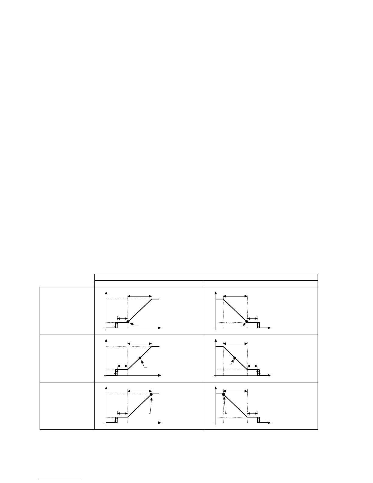
Type of set-point (not available in slave mode). Defines the position of the set-point within the control band (or differential) (parameter
C03)
CONTROL OPERATING MODES
“DIRECT” mode “REVERSE” mode
set-point at min. value
C03=0
cutoff
differential
temp.
setpoint
Vout %
max
min
cutoff
differential
temp.
setpoint
Vout %
max
min
set-point at average
value C03=1
cutoff
differential
temp.
setpoint
Vout %
max
min
cutoff
differenial
temp.
setpoint
Vout %
max
min
set-point at max. value
C03=2
cutoff
differential
temp.
setpoint
Vout %
max
min
cutoff
differential
temp.
setpoint
Vout %
max
min
Fig.3
• • Integral control action (not available in SLAVE mode)
The control action, normally proportional, can be modified to PI (proportional and integral) with programmable integral action (parameter
C09). In this case, the control acts so as to maintain the measured value within the control band, independently of the type of set-point
selected.

FCM electronic regulator Cod. +302235300 - Rel. 2.0 del 30/11/98
8
• • Second probe management (not available in slave mode)
The value of the measurement actually used by the controller depends on the two probe inputs, and can be selected (parameter C19)
keeping into consideration the following elements:
• probe 1 (probe 2 not used);
• greater value of the two probes (lower in reverse operation);
• lower value of the two probes (greater in reverse operation);
• difference between the two probes (probe1 - probe2);
• probe 1 for control, probe 2 for defrost control.
• • Detection of disconnected probe
When using NTC or 4÷20 mA probes, their disconnection is automatically detected. In this case, a message will be displayed, the control
action will be interrupted and the 0÷10 V output will be disabled or forced to the set value (parameter C10). When the connection is
restored, control is automatically resumed. The detection of disconnected probes concerns exclusively the probes being currently used.
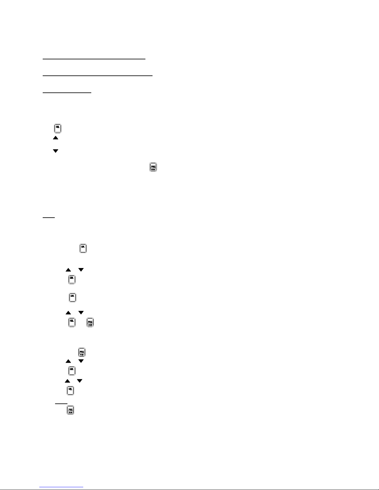
6.4 High and Low alarms (not available in slave mode)
If the measured value remains below the Low threshold (parameter P25) or above the High threshold (parameter P26) for a minimum
time defined by parameter P28, the dedicated alarm will be generated. A Low or High alarm condition results in the following signals:
• the buzzer sounds;
• a message appears on the display;
• energisation of the digital relay (if programmed);
• no effect on the control action.
Automatic disabling of the digital output can be programmed using parameter P27.
“P28”
“P26”
alarm
on
“P25”
on
TT
“P28”
“P27”
“P27”
Fig.4
In the event of High alarm in “direct” mode or Low alarm in “reverse” mode:
the 0÷10 V output can be forced to its max. value (100%) irrespective of the maximum programmed value (parameter C10). The output
remains at 100% for the entire duration of the alarm. It is recommended, in this case, to set a low value for the alarm differential
(parameter P27), so that the alarm deactivates as soon as the controlled value returns within the alarm threshold.
6.5 Defrosting (not available in SLAVE mode)
When in cooling/heating operating mode with Defrost management (parameter C00=8), it is possible to set a Defrost threshold that
starts a defrost cycle (parameter P40). Below this threshold (with a delay defined by parameter P42):
• defrost starts;
• the relay output is commuted;
• control action interrupts;
• the 0÷10 V output is forced to the value fixed by parameter P45.
The Defrost procedure may last until the set Defrost threshold which makes the cycle end (parameter P41) has been exceeded:
1. if you set the max. allowable time (defined by parameter P43) Ü on exceeding the maximum time an alarm signal is generated. The
frequency of defrost cycles can be limited, by setting a minimum time between consecutive defrost cycles (parameter P44);
2. if you want to set a fixed time (parameter P43) Ü the threshold ending the defrost cycle must be set to its maximum value.
Defrost control:
• uses the same probes as those used for normal control functions, or
• uses probe 2 for Defrost control and probe 1 for normal control action.
“P42”
T
temp
“P41”
“P40”
defrost
on
”P43”
Defrost inhibition caused by threshold exceeding
“P42”
T
temp
“P41”
“P40
defrost
on
<”P43”
Defrost inhibition caused by threshold exceeding

FCM electronic regulator Cod. +302235300 - Rel. 2.0 del 30/11/98
9
Fig.5

FCM electronic regulator Cod. +302235300 - Rel. 2.0 del 30/11/98
10
6.6 Multifunction digital inputs
The terminal block comes complete with two digital inputs which can be associated with two commands, whose function can be selected
by using parameters C29 and C30.
• automatically-reset alarm: when the contact opens, the analogue output is immediately forced to 0 V and the corresponding alarm is
generated. The alarm condition will persist until the contact closes.
• manually-reset alarm: when the contact opens, the analogue output will be immediately forced to 0 V and the corresponding alarm
will be generated. The alarm condition must be reset manually, that is acting on the keypad, after the contact has closed again.
• delayed alarm and manual reset: the same as the manually-reset alarm. The alarm will be generated as soon as the previously set
time-interval has passed (parameter P28).
• enabling/disabling: in the event of open contact, the analogue output is immediately forced to 0 V.
• max. value of the 0÷10 V output: in the event of closed contact, the analogue output is immediately forced to 10 V, independently of
the max. value given to the parameter.
You should notice the following:
1. If you select an operating mode which involves a command coming from terminal block (C00 grater or equal to 4), the command
automatically matches the ID1 input.
2. If both digital inputs are available and they are given the same function (alarm, enabling or output to 100%), ID1 has priority.
6.7 Multi-function digital output
The terminal block comes complete with a relay digital output which can be associated with one of the functions listed below. You can
select the normally energized relay or the normally disenergized relay option (parameter C31). When you select the Cooling/Heating
operation mode with defrost management (parameter C00=8), the relay is used to manage the defrost cycle, independently of the
previously set programmed functions.
• Alarm signal: generates in the event of any off-normal condition.
• Active 0-10V output signal: generates when the voltage supplied to the 0÷10 V output is different than 0 V.
• Signal of max. value of the output: generates when the voltage supplied to the 0÷10 V output has reached its max. programmed
value. It disappears when the hysteresis is 0.5 V. (The speed-up function does not affect this signal).
• On/Off regulation: starts when the voltage to the 0÷10 V output reaches its max. programmed value. It deactivates when the voltage to the
0÷10 V output reaches its min. programmed value. (The speed-up function does not affect this signal).
6.8 Extra LED indicators
The display shows:
• LED OUT ---> indicates the status of the 0÷10 V output of the controller
• LED AUX ---> its meaning depends on the selected operating mode
Fig. 6
Type Status Description
OUT off 0 V output
on output energized
blinking output at max. programmed voltage
AUX C00=0,1,2,3 off relay digital output disenergized
on relay digital output energized
C00=4,5,6,7 off input ID1 open (matched function not active)
on input ID1 closed (matched function active)
C00=8 off input ID1 open (cooling mode)
on input ID1 closed (heating mode)
blinking input ID1 closed (heating mode) and defrost commad active
Tab. 1
FCM electronic regulator Cod. +302235300 - Rel. 2.0 del 30/11/98
11
7 Programming FCM controllers
There are three groups of parameters which allow you to customize the use of the FCM instrument, according to your specific application
requirements:
"C" Parameters or configuration parameters: are to be set at the very beginning, depending on the features of your FCM, its inputs and
outputs.
"P" Parameters or frequently-used parameters: can be frequently modified in order to optimize the performance of the controller
according to changed operating conditions.
Set-point Parameters: can be easily accessed by the end-user without any technical support; they allow you to change the value of the
parameters to be controlled.
At start-up, after the initial waiting step displayed by "---", and during the normal operating mode, the value given to "C33" will be
displayed. (The symbol "---" will appear in the event of current disabling command coming from terminal block).
Main functions of the buttons:
• : press it to display the unit of measure of the parameter actually being displayed for 1 second .
• : press it to display the value of the 1st probe; this value is preceded by the corresponding unit of measure, displayed for 1 second
(even if the probe is disconnected).
• : press it to display the value of the 2nd probe; this value is preceded by the corresponding unit of measure, displayed for 1 second
(even if the probe is disconnected).
• When an alarm condition occurs, pressing once will silence the buzzer; if you press it a second time, the alarm signal is
cancelled (provided that the cause that generated the alarm has been removed).
The programming procedure includes three levels of accessibility to the parameters:
− display and modification of set-point parameters ONLY;
− display and modification of "P" (frequently-used) parameters, set-points included;
− display and modification of all parameters: set-point, "P" and "C" parameters.
Note: it is not possible to move from one level to another straightforwardly. To do so you must first bring the current programming
procedure to an end, then enter another programming level
7.1 Setting the set-point ("St" parameters)
1. hold down (for about 2 seconds) until "St1" appears on the display;
2. when SEL is released, the unit of measure of the set-point is displayed for 1 second; after that the display shows the current value of
the set-point;
3. press or to change its value (hold down the buttons to quickly increase or decrease the value);
4. press to confirm the displayed value. If there isn't a second set-point, the programming procedure is over, otherwise "St2" will
be displayed.
5. when is released, the unit of measure of the set-point is displayed for 1 second; after that the display shows the current value
of the set-point;
6. press or to change its value (hold down the buttons to quickly increase or decrease the value);
7. press or to confirm the displayed value and exit the programming procedure.
7.2 Accessing "P" parameters
1. hold down (for about 5 seconds) until "P01" appears;
2. press or to scroll all "P" parameters, set-points included (hold down the buttons to gradually increase the scrolling speed);
3. press to display the value of the selected parameter (the corresponding unit of measure will be displayed first for 1 second);
4. press or to change the value of the parameter (hold down the buttons to quickly increase or decrease the value);
5. press to confirm the displayed value. The identification code of the parameter will appear again on the display.
Note: to display and modify, if necessary, other parameters, repeat steps 2, 3, 4, 5 above.
6. press to save any modification and exit the programming procedure.

FCM electronic regulator Cod. +302235300 - Rel. 2.0 del 30/11/98
12
7.3 Accessing "C" parameters
1. hold down and together for about 5 seconds, until "00" appears on the display; after that digit the password;
2. press and to introduce the password ("77");
3. press to confirm the password. If the password is incorrect, the programming procedure will interrupt, otherwise "C00" will be
displayed.
4. press and to scroll the list of the parameters (hold the buttons down to scroll the parameters quickly);
5. press to display the value of the selected parameter (the corresponding unit of measure will be displayed first for 1 second);
6. press and
to change the value of the parameter (hold down the buttons to quickly increase or decrease the value);
7. press to confirm the displayed value. The identification code of the parameter will appear again on the display;
Note: to display and modify, if necessary, other parameters, repeat steps 4, 5, 6, 7 above.
8. press to save any modification and exit the programming procedure.
7.4 Validity of the modifications
Any modification will become operative as soon as it is confirmed by pressing . The following parameters, instead, will become
operative immediately: St1, St2, P01, P02, C04, C05, P25, P26, P27, P40, P41, P45.
Some parameters, especially those related to serial connection, will become operative only after you have re-started the
instrument.
After 5 seconds from the release of the last button during the programming phase, the display starts to flash (this means you are still
operating in the programming section). After 60 seconds from the release of the last button, during which the display shows the value of a
parameter, the previous modification will be neglected and the display will show the identification code of that parameter. After further 5
seconds, the display will start to flash again and after 60 seconds the programming procedure will automatically exit; the values of the
parameters will remain the same as the ones set before the programming phase.
If you are displaying the identification code of a parameter, the programming procedure will automatically exit after 60 seconds.
Display Unit of measure
°C temperature in degrees Centigrade
°F temperature in degrees Fahrenheit
rH relative humidity in %
bAr pressure in bar
SEc time in second (or milliseconds)
Min time in minutes
o
/
o
percent
h hexadecimal number
7.5 Displaying the unit of measure
Displaying the unit of measure is extremely useful as it avoids any misunderstanding of the values of each single parameter. The unit of
measure depends on the type of probe being used as well as on the configuration of the instrument. It is always possible, however, not to
make the unit of measure appear on the display, or make it appear only when you have to access parameters P and C (parameter C32). In
the event of an adimensional number, the unit of measure will not be displayed.
7.6 Setting min. and max. output values
In order to set-up the controller in the easiest way, you can avail yourself of a special procedure allowing you to set the minimum
(parameter C04) and maximum (parameter C05) values of the 0÷10 V output of the FCM controller. This function helps optimize the
performance of the connected fans.
Note: using this procedure means to energize the analogue output, that is, to actuate the rotation of the connected fans, independently of
the previously set operating mode and of any command coming from terminal block
To set the min. and max. output values follow the instructions below (at start up only):
1. press and
within 5 seconds from start-up until the display shows "C04";
2. press : the output energizes until it reaches the current value of the C04 parameter; its value will be displayed in percentage (the
variation speed of the output is 5% per second, that is 0.5 V/s). Press or
to interrupt the output variation before it reaches the
C04 value;
3. use and
to set the new value (hold the button down to increase/decrease the value of the parameter quickly);
4. press to confirm the new value. "C04" will appear on the display; the output will gradually go to zero;
5. press and
to display "C05";
6. to set the max. output value, follow the same indications as for the minimum value (using C05 instead of C04)
Note: the instructions above can be repeated as many times as you wish, according to your application requirements

FCM electronic regulator Cod. +302235300 - Rel. 2.0 del 30/11/98
13
7. press to store the new values (C04 and C05) and return to normal operation.
7.7 Factory-set parameters
Re-setting factory-set values can be done only at start-up, as follows:
1. hold down for about 5 seconds within 5 seconds from start-up until "-=-" is displayed (the dash on the top flashes);
2. release within 3 seconds so as to re-set and store the factory-set values. The symbol "-=-", which appears for 2 seconds, shows
that the procedure has been correctly carried out and the factory-set data have been stored.
If you do not release within 3 seconds, the parameters will NOT be modified (the symbol "---" will then be displayed).
7.8 Remote Control
In order to make the programming procedure of the FMC easier, Carel suggests using the remote control, not only to program data from a
remote position but also to set the most common and most used parameters quickly and easily. The remote control allows you to
display and modify set-points and all P and C parameters from a distant point. In addition, the availability of several buttons allows
you to access the main parameters directly. The FCM* series features the possibility of setting on each single instrument an access code
(parameter C51) which simplifies the use of the remote control. If, for example, your panel comprises several controllers, you can modify
the parameters of only one of them, just by digiting the code of the FCM controller whose data you wish to change.
Using the remote control is therefore time-saving and safe: any modification, in fact, requires you to press the ENABLE button to begin
the procedure (this avoids any involuntary modification of the parameters). In addition, C50 prevents any unauthorized use of the remote
control: depending on its value, C50 inhibits any modification or allows you to access and modify only P parameters.
7.9 Technical specifications
Power Supply 2 alkaline batteries, 1.5V (type UM-4 AAA, IEC R03)
Case plastic
Dimensions 60x160x18mm
Storage temperature -25°C÷70°C
Operating temperature 0°C÷50°C
Transmission type Infrared
Weight 80g (without batteries)
7.10 Description of the keypad
The buttons on the keypad can be divided into three groups, depending on their specific functions:
• buttons which enable/disable the use of the remote control;
• pre-programmed buttons to modify the main parameters;
• buttons for the remote control of the keypad of the FMC instrument.
Buttons which enable/disable the use of the remote control
These buttons allow you to enable the use of the remote control, to disable it and to give the parameters new
values, storing them (if necessary).
ENABLE
enables the use of the remote control
PRG
exits the programming stage and saves the new values
ESC
exits the programming stage and annuls any modification
numeric keypad
allows you to set the parameters' access code;
we recommend using the code especially when several devices are under the
beam of the infrared remote control, as in electrical panel including many
controllers.
Setting a different code for each single instrument allows you to modify the
parameters of only one specific controller.
Buttons which modify the main parameters (direct access buttons)
The most commonly used parameters are indicated on the remote control where you can see three different areas
on a light grey background:
• parameters related to set-points;
• display of any measurement (P parameters: reading only parameters);
• parameters related to the main regulation functions.
Buttons for the remote control of the keypad of the FMC instrument
The green section on the remote control reproduces the keypad of the FCM; this section allows you to perform the same operations as if
you were acting on the FCM keypad. This part includes the following buttons:
PRG
· saves any value and exits the programming procedure;
SEL
· displays the unit of measure and the value of the selected parameter;
· confirms the modified value and shows the identification code of the parameter;
· 1) goes from one parameter to the next one;
· 2) increases the value of the displayed parameter (while setting the parameter values)
- set point 1 +
- out min. +
- differenziale 1 +
- out max. +
- set point 2 +
- allarme Alta +
- differenziale 2 +
- cut-off +
sonda1 sonda2
- allarme Bassa +
son1&2 out
- speed-up +
PRG
s
- ritardo allarme +
SEL
t
- differenz. allar.+
3 4 1 2
5 6 7 8
9 0
ANNULLA INIZIO

FCM electronic regulator Cod. +302235300 - Rel. 2.0 del 30/11/98
14
· 1) goes from one parameter to the previous one;
· 2) decreases the value of the displayed parameter (while setting the parameter values)
7.11 Using the remote control
Access without code
1) ENABLING THE FCM CONTROLLER TO RECEIVE INSTRUCTIONS FROM THE REMOTE CONTROL
• Be sure not to be in the programming section; then press ENABLE to enable the use of the remote control;
• the identification code of the first accessible parameter appears on the display. If the display shows two digits, an enabling code
must be introduced (in this case see "Access with code" below).
2) MODIFICATION OF THE MAIN PARAMETERS
• press - or + until you reach the parameter whose value you want to change. After that the instrument displays the code of the
selected parameter (see codes at the end of this user manual or on the instruction sheet of your FCM instrument); when you press
these buttons a second time, the display will show the value given to that parameter;
• press + to increase its value;
• press - to decrease its value;
• to display one of the factory-set values, press the relevant button twice.
Note: when out of the programming phase, SEL (displaying the unit of measure), PRG (concerning alarm reset functions) and the
buttons allowing you to display directly the parameters are always enabled. You don't need to press ENABLE or insert the access code.
3) MODIFICATION OF THOSE PARAMETERS LACKING A DEDICATED BUTTON
The parameters which do not have a dedicated button can be modified as follows:
• carry out instructions as described in 1) above;
• press or
until the display shows the desired parameter;
• press SEL to display the value given to the selected parameter;
• press or
to increase or decrease its value;
• press SEL to confirm the new value and return to the main mask showing the identification code of the parameter;
• to modify another parameter repeat the procedure.
4) HOW TO EXIT THE PROGRAMMING PROCEDURE
• press PRG to exit and save any modification;
• press ESC to exit without saving any modification;
• do not press any key for 60 seconds if the identification code of the parameter is being displayed or for 120 seconds if the display
shows the value of the parameter: in both cases the controller automatically exits the programming procedure without saving any
modification.
Access with code
5) ENABLING THE FCM CONTROLLER TO RECEIVE INSTRUCTIONS FROM THE REMOTE CONTROL
• Be sure not to be in the programming section; then press ENABLE to enable the use of the remote control;
• all devices under the influence of the remote control's beam show their identification code;
•
insert the code of the controller whose parameters needs to be modified (use the numeric section on the keypad of the remote control).
Insert the right code adding zeroes if they are part of the code (IE: 05);
• if the code has been correctly inserted, the display will show the first accessible parameter;
• go on following points 2), 3), or 4) described above.
7.12 Setting the access code
The factory-set program automatically deactivates the access code. To activate it, modify parameter C51, giving it a value different from
0. To deactivate the code you have to give the value equal to 0 to parameter C51. In this way it is possible to use the remote control
without the access code.

FCM electronic regulator Cod. +302235300 - Rel. 2.0 del 30/11/98
15
8 Description of the parameters
8.1 Parameters concerning the set-point
St1: Set-point 1 (main)
St1 is the most important parameter; it is used in any operating mode, except in SLAVE.
Access:
Keypad: if C50=1, 3 or 4 Ü direct access pressing ;
if C50=0 or 2 Ü the parameter can only be displayed.
Remote Control: if C50=0, 1 or 4 Ü direct access pressing “ENABLE” and, after that, the dedicated buttons;
if C50=2 or 3 Ü the parameter can only be displayed.
Modes: in any operating modes except C00=0 and 1 (“SLAVE DIRECT” and “SLAVE REVERSE” modes)
Operating range: from -40°C (-40°F) to 100°C (212°F) for temperature
from 0.0 to 100 bar or rH for pressure and humidity
Default: St1=0.0.
St2: Set-point 2 (secondary)
St2 can be used alternatively to St1 in those operating modes based on the presence of St2.
Access:
Keypad: if C50=1, 3 or 4 Ü direct access pressing ;
if C50=0 or 2 Ü the parameter can only be displayed
Remote Control: if C50=0, 1 or 4 Ü direct access pressing "ENABLE” and, after that, the dedicated buttons:
if C50=2 or 3 Ü the parameter can only be displayed.
Modes: in modes based on the presence of two different set-points, C00=5, 6, 7 and 8
Other parameters: does not depend on other parameters.
Operating range: from -40°C (-40°F) to 100°C (212°F) for temperature
from 0.0 to 100 bar or rH for pressure or humidity
Default: St2=0.0.
C00: Operating mode
C00 is the most important configuration parameter. It defines the operating mode of the controller (see the description of the operating
modes above).
Access:
Keypad: if C50=1, 3 or 4 Ü + for 5” and password 77;
if C50=0 or 2 Ü the parameter can only be displayed.
Remote Control: if C50=4 Ü press “ENABLE” and and ;
Modes: available in all modes except C00=0 and 1 ('SLAVE DIRECT' and 'SLAVE REVERSE' modes)
Operating range: from 0 to 8
C00=0 Ü SLAVE DIRECT
C00=1 Ü SLAVE REVERSE
C00=2 Ü DIRECT
C00=3 Ü REVERSE
C00=4 Ü DIRECT & REVERSE (input ID1)
C00=5 Ü DIRECT-St1 & DIRECT-St2 (input ID1)
C00=6 Ü REVERSE-St1 & REVERSE -St2 (input ID1)
C00=7 Ü DIRECT -St1 & REVERSE -St2 (input ID1)
C00=8 Ü DIRECT -St1 & REVERSE -St2-Defrost (Defrost) (input ID1)
Default: C00 = 2 Ü DIRECT. .
P01: Differential of St1
P01 defines the hysteresis of St1 (that is the width of the regulation zone). It is a relative value which can have the same value as St1 or
can be set on its right or on its left.
Access:
Keypad: if C50=1 or 3 Ü press for 5”;
if C50=0, 2 or 4 Ü the parameter can only be displayed.
Remote control: if C50=0, 1 or 4 Ü direct access pressing "ENABLE" and, after that, the dedicated buttons
if C50= 2 or 3 Ü the parameter can only be displayed.
Modes: in all modes except C00=0 and 1 (“SLAVE DIRECT” and “SLAVE REVERSE” )
Operating range: from 0.0 to 100 (180°F).
Default: P01 = 2.0 (3.6°F).
Note: the type of set-point depends on C03.

FCM electronic regulator Cod. +302235300 - Rel. 2.0 del 30/11/98
16
P02: Differential of St2
P02 defines the hysteresis of St2 (that is the width of the regulation zone). It is a relative value which can have the same value as St2 or
can be set on its right or on its left.
Access:
Keypad: : if C50=1 or 3 Ü press for 5”;
if C50=0, 2 or 4 Ü the parameter can only be displayed.
Remote control: if C50=0, 1 or 4 Ü direct access pressing “ENABLE” and, after that, the dedicated buttons;
if C50= 2 or 3 Ü the parameter can only be displayed.
Modes: in modes based on the presence of two different set-points, C00=5, 6, 7 and 8
Other parameters: does not depend on other parameters.
Operating range: from 0.0 to 100 (180°F).
Default: P02 = 2.0 (3.6°F).
Note: the type of set-point depends on C03.
C03: Type of set-point
C03 indicates if the set-point corresponds to the min., max. or average value of the analogue output.
Access:
Keypad: if C50=1, 3 or 4 Ü press + for 5” and password 77;
if C50=0 or 2 Ü the parameter can only be displayed.
Remote control: if C50=4 Ü press “ENABLE” and and ;
Modes: in all modes except C00=0 and 1 (“SLAVE DIRECT” and “SLAVE REVERSE” )
Other parameters does not depend on other parameters.
Operating range: from 0 to 2
C03=0 Ü set-point corresponds to the min. output value
C03=1 Ü set-point corresponds to the average output value
C03=2 Ü set-point corresponds to the max. output value
Default: C03=0 Ü set-point corresponding to the min. output value.
8.2 Parameters concerning the analogue output
C04: Minimum output value
C04 defines the min. value of the 0÷10 V analogue output, expressed in %.
Access:
Keypad: if C50=1, 3 or 4 Ü + for 5” and password 77
if C50=0 or 2 Ü the parameter can only be displayed.
Remote control if C50=4 Ü direct access pressing “ENABLE” and, after that, the dedicated buttons.
Other parameters: does not depend on other parameters.
Operating range: from 0% to C05 (max. output value).
Default: C04 = 0%.
C05: Maximum output value
C05 defines the maximum value of the analogue output in %.
Access:
Keypad: if C50=1, 3 or 4 Ü + for 5” and password 77;
if C50=0 or 2 Ü the parameter can only be displayed.
Remote control: if C50=4 Ü direct access pressing “ENABLE” and, after that, the dedicated buttons
Other parameters: does not depend on other parameters.
Operating range: from C04 (min. output value) to 100%.
Default: C05 = 100% .
C06: Soft-start
C06 defines the max. variation speed necessary to change the value of the analogue output, that is the time interval necessary to pass
from 0 to 100% and vice-versa.
Access:
Keypad: if C50=1, 3 or4 Ü + for 5” and password 77;
if C50=0 or 2 Ü the parameter can only be displayed.
Remote control: if C50=4 Ü press “ENABLE” and and ;
Other parameters: does not depend on other parameters.
Operating range: from 0 to 120 seconds.
Default: C06 = 2 s. .
Note: setting too long time-intervals may cause hunting problems.

FCM electronic regulator Cod. +302235300 - Rel. 2.0 del 30/11/98
17
C07: Cut-off
C07 defines the threshold beyond which the analogue output disenergizes (0 V). It is expressed as a relative value and refers to the
minimum output value.
Access:
Keypad: if C50=1, 3 or 4 Ü + for 5” and password 77;
if C50=0 or 2 Ü the parameter can only be displayed.
Remote control: if C50=4 Ü direct access pressing “ENABLE” and, after that, the
dedicated buttons.
Modes: in all modes except C00=0 and 1 (“SLAVE DIRECT” and “SLAVE REVERSE”)
Other parameters: does not depend on other parameters.
Operating range: from 0.0 to 100 (180°F).
Default: C07 = 0.0.
Note: if you do not want to use the cut-off function, set a very high value. The cut-off threshold has a hysteresis of 0.3 (0.6°F).
C08: Speed-up
C08 defines the duration of the speed-up function, that is the time-interval during which the analogue output is forced to its maximum
programmed value (if energized).
Access:
Keypad: if C50=1, 3 or 4 Ü + for 5” and password 77;
if C50=0 or 2 Ü the parameter can only be displayed.
Remote control: if C50=4 Ü direct access pressing “ENABLE” and, after that, the dedicated buttons.
Modes: in all modes except C00=0 and 1 (“SLAVE DIRECT” and “SLAVE REVERSE”)
Other parameters: does not depend on other parameters.
Operating range: from 0 to 120 seconds.
Default: C08 = 0 s.
Note: in order not to use the speed-up function, set C08=0. Duration includes also the soft-start function.
C09: Integral action
C09 enables the PI regulation mode and defines its time-interval. With this regulation mode the running analogue output keeps the
regulated value exactly at the set point.
Access:
Keypad: if C50=1, 3 or 4 Ü + for 5” and password 77;
if C50=0 or 2 Ü the parameter can only be displayed.
Remote control: if C50=4 Ü press “ENABLE” and and ;
Modes: in all modes except C00=0 and 1 (“SLAVE DIRECT” and “SLAVE REVERSE” )
Other parameters: does not depend on other parameters.
Operating range: from 0 to 999 seconds.
Default: C09 = 0 s.
Note: the integral action is much more intense if the time interval is short. To disable the PI regulation set C09=0. When working in the
PI regulation mode, we suggest setting the set-point C03=1 (average value). In fact, the actual set-point corresponds to the central value
of the regulation zone, independently of the selected set-point
C10: Value of the output in the event of disconnected probe or high alarm
C10 defines the value of the analogue output in the event of disconnected probe or active high (temperature, pressure, humidity) alarm
(or low alarm in the reverse mode).
Access:
Keypad: if C50=1, 3 or 4 Ü press + for 5” and password 77;
if C50=0 or 2 Ü the parameter can only be displayed.
Remote control: if C50=4 Ü press “ENABLE” and and ;
Other parameters: does not depend on other parameters.
Operating range: from 0 to 5
C10=0 Ü disconnected probe: disenergized output (0%)
High(Low) alarm: normal output
C10=1 Ü disconnected probe: output=C04 (min. value)
High(low) alarm: normal output
C10=2 Ü disconnected probe: output=C05 (max. value)
High(Low) alarm: normal output
C10=3 Ü disconnected probe: disenergized output (0%)
High(Low) alarm: 100% output
C10=4 Ü disconnected probe: output=C04 (min. value)
High(Low) alarm: 100% output
C10=5 Ü disconnected probe: output=C05 (max. value)
High(Low) alarm: 100% output
Default: C10=0 Ü disconnected probe: disenergized output; High alarm: normal output.

FCM electronic regulator Cod. +302235300 - Rel. 2.0 del 30/11/98
18
8.3 Parameters concerning inputs
C13: Type of probes
C13 defines the type of electrical signal and the type of value measured by the probes.
Access:
Keypad: if C50=1, 3 or 4 Ü + for 5” and password 77;
if C50=0 or 2 Ü the parameter can only be displayed.
Remote control: if C50=4 Ü press “ENABLE” and and ;
Operating range: 0 for FCM00NTC00, 1 to 2 for FCM0001000, 3 to 7 for FCM0002000.
C13=0 Ü NTC probes (10 kΩ at 25°C)
C13=1 Ü 0÷10 V probes for temperature or humidity
C13=2 Ü 0÷10 V probes for pressure
C13=3 Ü 0÷20 mA probes for temperature or humidity
C13=4 Ü 0÷20 mA probes for pressure
C13=5 Ü 4÷20 mA probes for temperature or humidity
C13=6 Ü 4÷20 mA probes for pressure
C13=7 Ü CAREL 4÷20 mA probes for temperature or humidity
Default: C13 = 0 for FCM00NTC00, 1 for FCM0001000, 6 for FCM0002000.
Note: CAREL 4÷20 mA probes are connected according to the figures on page XXX, since it is expected
a 100Ω maximum load value resistance.
C14: Type of refrigerant
C14 defines the type of refrigerant. If your system includes pressure probes, the knowledge of the type of refrigerant allows you to convert
pressure into temperature.
Access:
Keypad: if C50=1, 3 or 4 Ü + for 5” and password 77;
if C50=0 or 2 Ü the parameter can only be displayed.
Remote control: if C50=4 Ü press “ENABLE” and and ;
Modes: in all modes except C00=0 and 1 (“SLAVE DIRECT” and “SLAVE REVERSE” )
Other parameters: depends on C13=2, 4 and 6 (pressure probes).
Operating range: from 0 to 7
C14=0 Ü unspecified refrigerant
C14=1 Ü R22
C14=2 Ü R404a
C14=3 Ü R407
C14=4 Ü R134a
C14=5 Ü R410a
C14=6 Ü R290 (propane)
C14=7 Ü NH3 (ammonia)
Default: C14 = 0 unspecified refrigerant
Not Available in FCM00NTC00.
Note: if the type of refrigerant is not specified, all the parameters concerning the measured variable will appear in bar. If the type of
refrigerant is specified, the pressure reading will be automatically converted into temperature and displayed on the basis of the unit of
measure as defined by C18.
C15: Minimum value of current or voltage inputs
C15 is the value measured when the input is given the min. possible signal, that is 0 V when using 0÷10 V probes, 0mA with 0÷20 mA
probes or 4 mA with 4÷20 mA probes.
Access:
Keypad: if C50=1, 3 or 4 Ü + for 5” and password 77;
if C50=0 or 2 Ü the parameter can only be displayed.
Remote control: if C50=4 Ü press “ENABLE” and and ;
Modes: in all modes except C00=0 and (“SLAVE DIRECT” and “SLAVE REVERSE” )
Operating range: from -40 to C16 for temperature probes in °C (C18=0) or °F (C18=1);
from 0.0 to C16 for humidity probes in rH (C18=2) or pressure probes in bar.
Default: C15 = 0.0
Not Available in FCM00NTC00.

FCM electronic regulator Cod. +302235300 - Rel. 2.0 del 30/11/98
19
C16: Maximum value of current or voltage inputs
C16 indicates the value measured when the input is given its maximum possible signal, that is 10 V when using 0÷10 V probes, 20 mA
with 0÷20 mA and 4÷20 mA probes.
Access:
Keypad: if C50=1, 3 or 4 Ü + for 5” and password 77;
if C50=0 or 2 Ü the parameter can only be displayed.
Remote control: if C50=4 Ü press “ENABLE” and and ;
Modes: in all modes except C00=0 and 1 (“SLAVE DIRECT” and “SLAVE REVERSE” )
Operating range: from C15 to 100 for temperature probes in °C (C18=0);
from C15 to 212 for temperature probes in °F (C18=1);
from C15 to 100 for humidity probes in rH (C18=2) or pressure probes in bar.
Default: C16 = 100 for FCM00NTC00 and FCM0001000, 30.0 for FCM0002000.
Not Available in FCM00NTC00.
C17: 'Filter' on probe input
C17 measures the effect of the 'filter' on the controlled value. It is the time constant of the filter.
When setting low values there is a low 'filtering' effect, with a quick reading of any variation measured by the sensor.
When setting high values the responses of the sensor are transmitted more slowly; this ensures greater immunity against noises, hence
steadier readings.
Access:
Keypad: if C50=1, 3 or 4 Ü + for 5” and password 77;
if C50=0 or 2 Ü the parameter can only be displayed.
Remote control: if C50=4 Ü press “ENABLE” and and ;
Other parameters: not accessible when using pressure probes with unspecified refrigerant (C13=2, 4, 6 and C14=0).
Operating range: from 0.0 to 10.0 seconds.
Default: C17 = 1.0 s.
C18: Unit of measure
C18 allows you to set the exact unit of measure for each parameter (St1, St2, P01, P02, C07, C15, C16, P40, P41, P25, P26, P27, P34,
P35, P36). The unit of measure will appear in bar only when you use pressure probes with types of refrigerant different from those listed
above (see C14).
Access:
Keypad: if C50=1, 3 or 4 Ü + for 5” and password 77;
if C50=0 or 2 Ü the parameter can only be displayed.
Remote control: if C50=4 Ü press “ENABLE” and and ;
Modes: in all modes except C00=0 and 1 (“SLAVE DIRECT” and “SLAVE REVERSE”)
Other parameters: not accessible when using pressure probes with unspecified refrigerant (C13 and C14).
Operating range: from 0 to 1 for FCM00NTC00
from 0 to 2 for FCM0001000 and FCM0002000.
C18=0 Ü °C (temperature in degrees Celsius)
C18=1 Ü °F (temperature in degrees Fahrenheit)
C18=2 Ü rH (relative humidity)
Default: C18 = 0 (°C).
C19: Second probe
C19 indicates how to use the second probe.
Access:
Keypad: if C50=1, 3 or 4 Ü + for 5” and password 77;
if C50=0 o 2 Ü the parameter can only be displayed.
Remote control: if C50=4 Ü press “ENABLE” and and ;
Modes: all modes except C00=0 and 1 (“SLAVE DIRECT” and “SLAVE REVERSE” )
Operating range: from 0 to 4
C19=0 Ü second probe not used (disconnected input)
C19=1 Ü the actual measure is the greater of the two probes (the lower in the “REVERSE” mode)
C19=2 Ü the actual measure is the lower of the two probes (the greater in the “REVERSE” mode)
C19=3 Ü the actual measure is the difference between probe 1 and probe 2
C19=4 Ü the second probe is used exclusively for defrost control
Default: C19 = 0 Ü second probe not used.

FCM electronic regulator Cod. +302235300 - Rel. 2.0 del 30/11/98
20
8.4 Alarm parameters
P25: Low threshold alarm
P25 identifies the threshold under which a Low (temperature, pressure, etc.) alarm is generated. P25 is an absolute value.
Access:
Keypad: if C50=1, 3 or 4 Ü press for 5”;
if C50=0 or 2 Ü the parameter can only be displayed.
Remote control: if C50=0, 1 or 4 Ü direct access pressing “ENABLE” and, after that, the dedicated buttons;
if C50=2 or 3 Ü the parameter can only be displayed..
Modes: all modes except C00=0 and 1 (“SLAVE DIRECT” and “SLAVE REVERSE”)
Operating range: from -40 to P26 for temperature probes or pressure probes with specified refrigerant, in °C (C18=0) or
°F (C18=1);
from 0.0 to P26 for humidity probes in rH (C18=2) or pressure probes with unspecified refrigerant in bar.
Default: P25 = -40 for FCM00NTC00 and FCM0001000 (threshold excluded)
0.0 for FCM0002000 (threshold excluded).
Note: the alarm will be generated keeping into consideration the time-delay selected through the P28 parameter. Its automatic reset
depends on the selected alarm differential P27. The alarm can be disabled giving P25 its minimum value
P26: High threshold alarm
P26 indicated the threshold beyond which the high (temperature, pressure, etc.) alarm is generated. It is an absolute value.
Access:
Keypad: if C50=1, 3 or 4 Ü press for 5”;
if C50=0 or 2 Ü the parameter can only be displayed.
Remote control: if C50=0, 1 or 4 Ü direct access pressing “ENABLE” and, after that, the dedicated buttons;
if C50=2 or 3 Ü the parameter can only be displayed.
Modes: all modes except C00=0 and 1 (“SLAVE DIRECT” and “SLAVE REVERSE” )
Operating range: from P25 to 100 for temperature probes or pressure probes with specified refrigerant in °C (C18=0);
from P25 to 212 for temperature probes or pressure probes with specified refrigerant in °F (C18=1);
from P25 to 100 for humidity probes in rH (C18=2) or pressure probes with unspecified refrigerant in bar.
Default: P26 = 100 (212°F) - threshold excluded.
Note: the alarm will be generated keeping into consideration the time-delay selected through the P28 parameter. Its automatic reset
depends on the alarm differential P27. The alarm can be disabled giving P26 its maximum value.
P27: Low/High Alarm Differential
P27 indicates the hysteresis between the value that generates a Low or High (temperature, pressure, etc.) alarm and the value which
deactivates it.
Access:
Keypad: if C50=1, 3 or 4 Ü press for 5”;
if C50=0 or 2 Ü the parameter can only be displayed.
Remote control: if C50=0, 1 or 4 Ü direct access pressing “ENABLE” and, after a that, the dedicated buttons;
if C50=2 or 3 Ü the parameter can only be displayed.
Modes: in all modes except C00=0 and 1 (“SLAVE DIRECT” and “SLAVE REVERSE” )
Operating range: from 0.0 to 100 (180°F)
Default: P27 = 2.0 (3.6°F)
Note: if the controlled parameter has almost restored its normal values but is still beyond its high or low thresholds, you can cancel the
alarm indication pressing . In order not to reset alarms automatically, give P27 a very high value.
P28: Time-delay before generating an alarm
P28 allows you to set a time-delay before the activation of Low/High (temperature, pressure) alarms after the P25 or P26 threshold has
been exceeded. It can also be applied to external alarms.
Access:
Keypad: if C50=1, 3 or 4 Ü press for 5”;
if C50=0 or 2 Ü the parameter can only be displayed..
Remote control: if C50=0, 1 or 4 Ü direct access pressing “ENABLE” and, after that, the dedicated buttons;
if C50=2 or 3 Ü the parameter can only be displayed.
Operating range: from 0 to 999 seconds.
Default: P28 = 1 s.
Note: if the controlled variable returns above the Low threshold alarm P25 or below the High alarm threshold P26 or if the external
alarm signal returns to normal values before the time-delay has passed, no alarm will be generated.

FCM electronic regulator Cod. +302235300 - Rel. 2.0 del 30/11/98
21
8.5 Parameters concerning digital inputs and output
C29: Multifunction digital input ID1
C29 indicates the function of the digital input ID1.
Access:
Keypad: if C50=1, 3 or 4 Ü + for 5” and password 77;
if C50=0 or 2 Ü the parameter can only be displayed..
Remote control: if C50=4 Ü press “ENABLE” and and ;
Modes: only when C00=0, 1, 2, 3
Operating range: from 0 to 5
C29=0 Ü input not used
C29=1 Ü external alarm and automatic reset (alarm with open input)
C29=2 Ü external alarm and manual reset (alarm with open input)
C29=3 Ü delayed external alarm and manual reset (alarm with open input; time-delay set by P28)
C29=4 Ü On/Off regulation (off when open input): when in the Off status, the analogue output will be immediately
disenergized (0 V)
C29=5 Ü energization of the 0÷10 V analogue output to 100%: when the input is closed, the analogue output is forced
to 0 V.
Default: C29 = 0 Ü input not used.
Note: if the function associated with the input ID1 is the same as that associated with the input ID2, ID1 has priority
C30: Multifunction digital input ID2
C30 indicates the function of the digital input ID2.
Access
Keypad: if C50=1, 3 or 4 Ü + for 5” and password 77; if C50=0 or 2 Ü the param. can only be displayed.
Remote control: if C50=4 Ü press “ENABLE” and and ;
Operating range: from 0 to 5
C30=0 Ü input not used
C30=1 Ü external alarm and automatic reset (alarm with open input)
C30=2 Ü external alarm and manual reset (alarm with open input)
C30=2 Ü external alarm and manual reset (alarm with open input)
C30=3 Ü delayed external alarm and manual reset (alarm with open input): time-delay set by P28
C30=4 Ü On/Off regulation (off when open input): when in the Off status, the analogue output will be immediately
disenergized (0 V)
C30=5 Ü energization of the 0÷10 V analogue output to 100%: when the input is closed, the analogue output is forced
to 0 V.
Default: C30 = 0 Ü input not used
Note: if the function associated with the input ID1 is the same as that associated with the input ID2, ID1 has priority
C31: Multifunction (relay) digital output
C31 indicates the function of the relay digital output (if not differently used according to the selected operating mode).
Access:
Keypad: if C50=1, 3 or 4 Ü + for 5” and password 77; if C50=0 or 2 Ü the param. can only be displayed..
Remote control: if C50=4 Ü press “ENABLE” and and ;
Modes: not available when C00=8
Operating range: from 0 to 8
C31=0 Ü output not used (disenergized relay)
C31=1 Ü disenergized relay in the event of generic alarm
C31=2 Ü energized relay in the event of generic alarm
C31=3 Ü disenergized relay in the event of active analogue output
C31=4 Ü energized relay in the event of active analogue output
C31=5 Ü disenergized relay when the analogue output has its max. value (hysteresis 0.5 V)
C31=6 Ü energized relay when the analogue output has its max. value (hysteresis 0.5 V)
C31=7 Ü disenergized relay when the analogue output reaches its max. value; energized relay when the
analogue output reaches its min. value (On/Off regulation)
C31=8 Ü energized relay when the analogue output reaches its max. value; disenergized relay when the
analogue output reaches its min. value (On/Off regulation).
Default: C31 = 0 Ü output not used.

FCM electronic regulator Cod. +302235300 - Rel. 2.0 del 30/11/98
22
8.6 Parameters concerning the unit of measure
C32: Displaying the unit of measure
C32 defines if and when it is necessary to display the unit of measure.
Access:
Keypad: if C50=1, 3 or 4 Ü + for 5” and password 77;
if C50=0 or 2 Ü the parameter can only be displayed..
Remote control: if C50=4 Ü press “ENABLE” and and ;
Operating range: from 0 to 3 when using pressure probes with specified refrigerant
from 0 to 2 in the other cases
C32=0 Ü display always disabled
C32=1 Ü display enabled only when accessing the parameters, except set-points
C32=2 Ü display always enabled
C32=3 Ü display always enabled; display of the variable in bar only
Default: C32 = 2 Ü display always enabled..
Note: when C32=3 it is possible to manage all the parameters concerning that variable in degrees and to display the measure of the
probes in bar. We suggest using this mode only to test the instrument during installation.
C33: Normally displayed value
C33 defines the indications normally displayed when you are not programming the instrument.
Access:
Keypad: if C50=1, 3 or 4 Ü + for 5” and password 77;
if C50=0 or 2 Ü the parameter can only be displayed..
Remote control: if C50=4 Ü press “ENABLE” and and ;
Operating range: from 0 to 5
C33=0 Ü displays the actual measure depending on C19
C33=1 Ü displays the measure of probe 1 (main probe)
C33=2 Ü displays the measure of probe 2 (secondary probe)
C33=3 Ü displays the % value of the analogue output
C33=4 Ü displays the % value of the input of probe 1
C33=5 Ü displays the status of the digital inputs and outputs (starting from the left you can see the status of
input ID1, ID2 and of the output; 0 indicates the 'off' status, 1 the 'on' status).
Default: C33 = 1 Ü measure of probe 1.
Note: C33=4 has some meaning only in models FCM0001000 and FCM0002000 working in the SLAVE mode where it makes the
instrument display the command signal in %. In the FCM00NTC00 model zero will be displayed.
P34: Displaying the actual measure depending on C19
The parameter can only be displayed.
Access:
Keypad: press for 5 seconds
Remote control: immediate display using the dedicated button.
P35: Displaying the measure of probe 1 (main probe)
The parameter can only be displayed.
Access:
Keypad: immediate display holding down or for 5 seconds;
Remote control: immediate display using the dedicated button.
P36: Displaying the measure of probe 2 (secondary probe)
The parameter can only be displayed.
Access:
Keypad: immediate display holding down or for 5 seconds;
Remote control: immediate display using the dedicated button.
P37: Displaying the % value of the analogue output
The parameter can only be displayed.
Access:
Keypad: press for 5 seconds;
Remote control: immediate display using the dedicated button.

FCM electronic regulator Cod. +302235300 - Rel. 2.0 del 30/11/98
23
P38: Displaying the % value of the input of probe 1
The parameter can only be displayed.
Access:
Keypad: press for 5 seconds;
Remote control: press “ENABLE” and and
Note: P38 has some meaning only in models FCM0001000 and FCM0002000 working in the SLAVE mode where it makes the
instrument display the command signal in %. In the FCM00NTC00 model zero will be displayed.
P39: Displaying the status of digital inputs and outputs
The parameter can only be displayed. It shows the status of input ID1, ID2 and of the output: 0 Ü off status;
1 Ü on status;
Access:
Keypad: press for 5 seconds;
Remote control: press “ENABLE” and and ;
Operating range: from 00.0 to 11.1
8.7 Parameters concerning defrost
P40: Defrost threshold
P40 indicates the threshold below which defrost starts. It is an absolute value.
Access:
Keypad: if C50=1, 3 or 4 Ü press for 5 seconds;
if C50=0 or 2 Ü the parameter can only be displayed.
Remote control: if C50=0, 1 or 4 Ü press “ENABLE” and and ;
if C50=2 or 3 Ü the parameter can only be displayed.
Modes: only when C00=8
Operating range: from-40 to P41 for temperature probes or pressure probes with specified refrigerant in °C (C18=0) or
°F (C18=1);
from 0.0 to P41 for humidity probes in rH (C18=2) or pressure probes with specified refrigerant, in bar.
Default: P40 = 0.0 (32.0°F).
Note: defrost depends also on the time-delay selected through the parameter P42 and on the minimum time-interval between two
defrosting cycles selected through P44.
P41: Threshold defining the end of defrost cycle
P41 defines the threshold above which defrost ends. It is an absolute value.
Access:
Keypad: if C50=1, 3 or 4 Ü press for 5 seconds;
if C50=0 or 2 Ü the parameter can only be displayed.
Remote control: if C50=0, 1 or 4 Ü press “ENABLE” and and ;
if C50=2 or 3 Ü the parameter can only be displayed.
Modes: only when C00=8.
Operating range:
from P40 to 100 for temperature probes or pressure probes with specified refrigerant in °C (C18=0);
from P40 to 212 for temperature probes or pressure probes with specified refrigerant in °F (C18=1);
from P40 to 100 for humidity probes in rH (C18=2) or pressure probes with unspecified refrigerant in bar.
Default: P41 = 100 (212°F) - threshold excluded.
Note: the defrost cycle may come to an end also when the max. time-interval selected through P43 has passed. In this case a dedicated
message will be displayed. P41 can be excluded giving it its max. value (in this case the defrost cycle will always end when its max.
duration has passed, without any message on the display).
P42: Time-delay before starting a defrost cycle
P42 defines the time-delay before starting a defrost cycle, after the threshold set through P40 has been exceeded.
Access:
Keypad: if C50=1, 3 or 4 Ü press for 5 seconds;
if C50=0 or 2 Ü the parameter can only be displayed.
Remote control: if C50=0, 1 or 4 Ü press “ENABLE” and and ;
if C50=2 or 3 Ü the parameter can only be displayed.
Modes: only when C00=8
Operating range: from 0 to 240 (seconds).
Default: P42 = 5 s.
Note: if the value goes above the P40 threshold before the end of the time-delay, the delay will be zeroed .

FCM electronic regulator Cod. +302235300 - Rel. 2.0 del 30/11/98
24
P43: Max. duration of defrost
P43 defines the max. duration of a defrost cycle.
Access:
Keypad: if C50=1, 3 or 4 Ü press for 5”;
if C50=0 or 2 Ü the parameter can only be displayed.
Remote control: if C50=0, 1 or 4 Ü press “ENABLE” and and ;
if C50=2 or 3 Ü the parameter can only be displayed.
Modes: only when C00=8
Operating range: from 1 to 60 minutes.
Default: P43 = 1 minute.
Note: if the P41 threshold has been excluded, P43 sets the fixed time for a defrost cycle. When P41 is operative P43 defines the max.
time beyond which the defrost cycle will come to an end; the display will then show a message.
P44: Min. time-interval between two defrost cycles
P44 sets the min. time-interval between a defrost cycle and the next one.
Access:
Keypad: if C50=1, 3 or 4 Ü press for 5 seconds;
if C50=0 or 2 Ü the parameter can only be displayed.
Remote control: if C50=0, 1 or 4 Ü press “ENABLE” and and ;
if C50=2 or 3 Ü the parameter can only be displayed.
Modes: only when C00=8
Other parameters: does not depend on other parameters.
Operating range: from 1 to 240 minutes.
Default: 1 minute.
Note: if the duration of the defrost cycle (P43) is greater than or equal to P44, the defrost will go on provided that the value of the
variable remains below P40.
P45: Value of the output during defrost
P45 sets the value of the 0÷10 V analogue output during a defrost cycle.
Access:
Keypad: if C50=1, 3 or 4 Ü press for 5 seconds;
if C50=0 or 2 Ü the parameter can only be displayed.
Remote control: if C50=0, 1 or 4 Ü press “ENABLE” and and ;
if C50=2 or 3 Ü the parameter can only be displayed.
Modes: only when C00=8.
Other parameters: does not depend on other parameters.
Operating range: from 0 to 100%.
Default: P45 = 0.
8.8 Parameters concerning keypad and remote control
C50: Enabling keypad and remote control
C50 allows you to limit or prevent any modification of the parameters by non authorized personnel.
Access:
Keypad: + for 5 seconds and password 77;
Remote control: if C50=4 Ü press “ENABLE” and and
.
Other parameters: does not depend on other parameters.
Operating range: from 0 to 4
C50=0 Ü Keypad: disabled (parameters can be only displayed except C50)
Remote control: parameters P and set-point can be modified, parameters C can't be seen;
C50=1 Ü Keypad: enabled;
Remote control: parameters P and set-points can be modified; parameters C can't be seen;
C50=2 Ü Keypad: disabled (only displayed parameters, except C50);
Remote control: disabled (parameters P and set-point can only be displayed);
C50=3 Ü Keypad: enabled;
Remote control: disabled (parameters P and set-point can only be displayed);
C50=4 Ü Keypad: enabled;
Remote control: enabled;
Default: C50 = 4 Ü Keypad and remote control enabled.

FCM electronic regulator Cod. +302235300 - Rel. 2.0 del 30/11/98
25
C51: Code enabling the remote control
C51 allows you to give each controller a code to access parameters via remote control. If your control panel comprises several
instruments, press “ENABLE” on the remote control to give each instrument a different access code.
Access:
Keypad: if C50=1, 3 or 4 Ü + for 5 seconds and password 77;
if C50=0 or 2 Ü the parameter can only be displayed.
Remote control: if C50=4 Ü press “ENABLE” and and .
Operating range: from 0 to 99
Default: C51 = 0 Ü code disabled
Note: if the code is not operative (C51=0) the identification procedure will fail. When you use the buttons of the remote control to
display values, all instruments will display what you have selected, independently of their identification code (unless you are
programming the instruments).
8.9 Parameters concerning serial connection
C52: Type of serial connection
C52 enables and defines the type of serial connection.
Access:
Keypad: if C50=1, 3 or 4 Ü + for 5 seconds and password 77;
if C50=0 or 2 Ü the parameter can only be displayed.
Remote control: if C50=4 Ü press “ENABLE” and and .
Operating range: from 0 to 2
C52=0 Ü disabled connection
C52=1 Ü connection to supervisory network (protocol Supervisor 3.0)
C52=2 Ü connection to pLAN network
Default: C52 = 1 Ü supervisory network
Note: using the serial connection requires the FCSER00000 option. Any modification of this parameter will become operative after
you have turned the instrument on again.
C53: Serial address
C53 gives each device a specific address. All data with address equal to C53 are accepted by the device.
Access:
Keypad: if C50=1, 3 or 4 Ü + for 5 seconds and password 77;
if C50=0 or 2 Ü the parameter can only be displayed.
Remote control: if C50=4 Ü press “ENABLE” and and .
Operating range: from 0 to 255.
Default: C53 = 0.
Note: using the serial connection requires the FCSER00000 option. The pLAN network makes use of addresses ranging from 1 to 32.
C54: Baud-rate / data destination address
Depending on the type of connection, C54 may define:
• supervision: transmission speed (baud-rate);
• pLAN: the address of the instrument to which data are sent.
Access:
Keypad: if C50=1, 3 or 4 Ü + for 5 seconds and password 77;
if C50=0 or 2 Ü the parameter can only be displayed.
Remote control: if C50=4 Ü press “ENABLE” and and .
Other parameters: depends on C52.
Operating range: from 0 to 3 if C52=1 (supervisor)
C54=0 Ü 1200 Bd
C54=1 Ü 2400 Bd
C54=2 Ü 4800 Bd
C54=3 (o > 3) Ü 9600 Bd
from 0 to 32 if C52=2 (pLAN)
Default:C54 = 0.
Note: using the serial connection requires the FCSER00000 option. Any modification of this parameter will become operative after
you have turned the instrument on again (connection to supervisory network only).

FCM electronic regulator Cod. +302235300 - Rel. 2.0 del 30/11/98
26
C55: Frame / page
Depending on the communication protocol, C55 defines:
• supervision: data structure (frame);
• pLAN: the page of the device where data will be received.
Access:
Keypad: if C50=1, 3 or 4 Ü + for 5 seconds and password 77;
if C50=0 or 2 Ü the parameter can only be displayed.
Remote control: if C50=4 Ü press “ENABLE” and and .
Other parameters: depends on C52.
Operating range: from 0 to 11 if C52=1 (supervision)
C55=0 Ü 8 bit/character, no parity, 2 stopbits (8,N,2)
C55=1 Ü 8 bit/character, no parity, 1 stopbit (8,N,1)
C55=2 Ü 8 bit/character, even parity, 2 stopbit (8,E,2)
C55=3 Ü 8 bit/character, even parity, 1 stopbit (8,E,1)
C55=4 Ü 8 bit/character, odd parity, 2 stopbit (8,O,2)
C55=5 Ü 8 bit/character, odd parity, 1 stopbit (8,O,1)
C55=6 Ü 7 bit/character, no parity, 2 stopbit (7,N,2)
C55=7 Ü 7 bit/character, no parity, 1 stopbit (7,N,1)
C55=8 Ü 7 bit/character, even parity, 2 stopbit (7,E,2)
C55=9 Ü 7 bit/character, even parity, 1 stopbit (7,E,1)
C55=10 Ü 7 bit/character, odd parity, 2 stopbit (7,O,2)
C55=11 (o >11) Ü 7 bit/character, odd parity, 1 stopbit (7,O,1), from 0 to 255 if C52=2 (pLAN)
Default: C55 = 0.
Note: using the serial connection requires the FCSER00000 option. Any modification of this parameter will become operative after
you have turned the instrument on again (connection to supervisory network only).
C56: Delayed response
C56 is used only when the controller is connected to a supervisory network. It allows you to set a time-delay before sending back data so
as to let the calling device take time to commute itself from a transmitter to a receiving unit.
Access:
Keypad: if C50=1, 3 or 4 Ü + for 5 seconds and password 77;
if C50=0 o 2 Ü the parameter can only be displayed..
Remote control: if C50=4 Ü press “ENABLE” and and ;
Operating range: from 0 to 200 milliseconds.
Default: C56 = 50 milliseconds.
Note: using the serial connection requires the FCSER00000 option.
C57: Enabling the hardware board
C57 allows you to eliminate some functions from the hardware board and manage them via serial connection.
Access:
Keypad: if C50=1, 3 or 4 Ü + for 5 seconds and password 77;
if C50=0 or 2 Ü the parameter can only be displayed.
Remote control: if C50=4 Ü press “ENABLE” and and .
Operating range: from 0 to 255.
bit0 (weight 1) Ü 1=display controlled by user interface;
0=display idle or controlled via serial line;
bit1 (weight 2) Ü 1=input ID1 controlled by terminal block;
0=input ID1 idle or controlled via serial line;
bit2 (weight 4) Ü 1=input ID2 controlled by terminal block;
0=input ID2 idle or controlled via serial line;
bit3 (weight 8) Ü 1=relay output controlled by terminal block;
0=relay output idle or controlled via serial line;
bit4 (weight 16) Ü 1=B1 probe input controlled by terminal block;
0=B1 probe input idle or controlled via serial line;
bit5 (weight 32) Ü 1=B2 probe input controlled by terminal block;
0=B2 probe input idle or controlled via serial line;
bit6 (weight 64) Ü 1=0÷10 V output (soft-start) controlled by terminal block;
0=0÷10 V output (soft-start) idle or controlled via serial line;
bit7 (weight 128) Ü not used.
Default: C57 = 255 Ü fully enabled.
Note: if you set C57 different from 255, some functions will not be performed. For example, if during normal operation the 0÷10 V
output is at 9 V and C57 is modified from 255 to 127 (255-128), then the 0÷10 V output will stick to 9 V independently of any value
given to the parameters, of any signal or external command (except, obviously, when C57=255).

FCM electronic regulator - Preliminary version Cod. +302235300 - Rel. 2.0 del 30/11/98
27
9 Table of Parameters
Parameter Min Max Def U.M. Nuovi
PASSWORD
77 -
PARAMETERS CONCERNING THE SET-POINT
St1
(*) Set-point 1 (main) -40
0.0
100
100
0.0 °C
r.H./bar
St2 (*) Set-point 2 (secondary) - parameter accessible only if C00=5, 6, 7, 8
-40
0.0
100
100
0.0 °C
r.H./bar
C00
Operating mode:
0= Slave direct
1= Slave reverse
2= Direct
3= Reverse
4= Dir. & Rev. (from input ID1)
5= Dir-St1 & Dir-St2 (from input ID1)
6= Rev-St1 & Rev -St2 (from input ID1)
7= Dir-St1 & Rev-St2 (from input ID1)
8= Dir.-St1 & Rev-St2-Defrost (from ID1)
0 8 2 -
P01
(*) Differential of St1 0.0 100 2.0 °C/r.H./bar
P02 (*) Differential of St2 - parameter accessible only if C00=5, 6, 7, 8
0.0 100 2.0 °C/r.H./bar
C03
(*) Type of Set-point
0=Set-point corresponding to the min. output value
1=Set-point corresponding to the average output value
2=Set-point corresponding to the max. output value
0 2 0 -
ANALOGUE OUTPUT
C04
Min. output value 0 C05 0 %
C05
Max. output value C04 100 100 %
C06
Soft-start 0 120 2 s
C07
(*) Cut-off 0.0 100 0.0 -
C08
(*) Speed-up 0 120 0 s
C09
(*) Integral action 0 999 0 s
C10
Output value with disconnected probe or High alarm
0=discon. probe: disabled out. (0%), High(Low) alarm: normal output
1=discon. probe: output at C04 (min value), High(Low) alarm: normal output
2=discon. probe: out. at C05 (max value), High(Low) alarm: normal output
3=discon. probe: disabled out. (0%), High(Low) alarm: out. at 100%
4=discon. probe: out. at C04 (min value), High(Low) alarm: out. at 100%
5=discon. probe: out. at C05 (max value), High(Low) alarm: out. at 100%
0 5 0 -

FCM electronic regulator - Preliminary version Cod. +302235300 - Rel. 2.0 del 30/11/98
28
INPUTS
C13
Probe type
FCM00NTC00 = 0= NTC probes (10 kΩ at
FCM0001000 = 1=0÷10V probes for Temp. or Humidity
FCM0002000 = 2=0÷10 V probes for Pressure
3=0÷20 mA probes for T. or H.
4=0÷20 mA probes for P.
5=4÷20 mA probes for T. or H.
6=4÷20 mA probes for P.
7=Carel 4÷20 mA probes for Temp. and Humidity
0
1
3
0
2
6
0
1
6
-
C14* Type of refrigerant - accessible only when C13=2, 4, 6
0=unspecified refrigerant; 1=R22, 2=R404a, 3=R407, 4=R134a, 5=R410a, 6=R290 (propane), 7=NH3 (ammonia)
0 7 0 -
C15*
Min. value for current or voltage inputs.
Not accessible when C13=0
-40
0.0
C16
C16
0.0 °C
r.H./bar
C16* Max. value for current or voltage inputs, not accessible when C13=0
C15 100 100 (**) °C/r.H./bar
C17
Filtering action at probe input 0,0 10,0 1.0 s
C18* Unit of measure: 0=°C, 1=°F, 2=rH - parameter not accessible when C13=2, 4, 6 and C14=0
0 2 0 -
C19*
Second probe management
0=second probe not used (disconnected input)
1=actual measure =t he greater of the two probes (the lower in “reverse” mode)
2=actual measure = the lower of the two probes (the greater in “reverse” mode)
3=actual measure = difference between probe 1 and probe 2
4=probe 2 used to control defrost cycles
0 4 0 -
ALARMS
P25*
Threshold of Low (T., P..) alarm -40
0.0
P26
P26
-40 (***) °C
r.H./bar
P26*
Threshold of High (T., P..) alarm P25 100 100 °C/r.H./bar
P27*
Differential of High and Low Alarm 0.0 100 2.0 °C/r.H./bar
P28
Delayed alarm 0 999 1 s
DIGITAL INPUTS and OUTPUTS
C29
Multi-function digital input ID1 (for the codes: see C30 parameter)
parameter accessible only if C00=0, 1, 2, 3.
0 5 0
C30
Multi-function digital input ID2
0=input not used 1=external alarm and automatic reset (alarm with open input)
2=ext. alarm and manual reset (alarm with open input)
3=delayed external alarm and manual reset (alarm with open input; time-delay defined by P28))
4=On/Off regulation (off with open input) in case of off, the analogue out. dis-energises immediately (0 V)
5=0÷10 V analogue out. Energises to 100%; in case of closed input, the analogue out. is forced to 10V.
0 5 0 -

FCM electronic regulator - Preliminary version Cod. +302235300 - Rel. 2.0 del 30/11/98
29
C31 Multi-function digital output (relay) - parameter not accessible when defrost is enabled (C00=8)
0=output not used (disenergized relay)
1=disenergized relay in the event of generic alarm
2=energized relay in the event of generic alarm
3=disenergized relay in the event of active analogue output
4=energized relay in the event of active analogue output
5=disenergized relay when the analogue output has its max. value (hysteresis 0.5 V)
6=energized relay when the analogue output has its max. value (hysteresis 0.5 V)
7=disenergized relay when the analogue output reaches its max. value; energized relay when the analogue output
reaches its min. value (On/Off regulation)
8=energized relay when the analogue output reaches its max. value; disenergized relay when the analogue output
reaches its min. value (On/Off regulation).
0 8 0 -
PARAMETERS CONCERNING THE CONTROLLED VARIABLE
C32
Displaying the unit of measure:
0= disabl.,
1=enabled, only when accessing parameters, Set-point excluded
2=always enabled,
3= always enabled, displaying measures in bar only.
0 3 2 -
C33
Normally displayed value:
0=actual measure related to C19,
1=measure of probe 1 (main probe);
2= measure of probe 2 (secondary);
3= % value of analogue output;
4= % value of probe 1 input
5= status of digital I/O
0 5 1
P34
Displaying the actual measure (depending on C19) - - - -
P35
Displaying value of probe 1 (main probe) - - - -
P36
Displaying value of probe 2 (secondary probe) - - - -
P37
Displaying % value of analogue output - - - -
P38
Displaying % value of probe 1 input - - - -
P39
Displaying status of digital inputs and outputs 00.0 11.1 - -
PARAMETERS CONCERNING DEFROST
Accessible only when C00=8
P40*
Defrost threshold causing defrost to start -40
0.0
P41
P41
0.0 °C
r.H./bar
P41*
Defrost threshold causing defrost to end P40 100 100 °C/r.H./bar
P42*
Time-delay before defrost end 0 240 5 secondi
P43*
Max. duration of defrost 1 60 1 minuti
P44*
Min. time-interval between 2 defrost cycles 1 240 1 minuti
P45*
Output value during defrost 0 100 0 %

FCM electronic regulator - Preliminary version Cod. +302235300 - Rel. 2.0 del 30/11/98
30
PARAMETERS CONCERNING KEYPAD/REMOTE CONTROL
C50
Enabling Keypad and Remote control:
0=keypad disabled; rem.control: param. P and St1 can be modified, par. C can't be seen.
1=keypad enabled; rem. control: param. P and St can be modified, param. C can't be seen.
2= keypad disabled; rem.control disabled (param. P and St can only be displayed).
3=keypad enabled; rem. control disabled (param. P and St can only be dispalyed).
4=keypad enabled; rem.control enabled.
0 4 4 -
C51
Code to enable the remote control 0 99 0 -
PARAMETERS CONCERNING SERIAL CONNECTION
C52
Type of serial connection:
0=no connection
1=supervisory network (protocol Supervisor 3.0)
2=connection to pLAN network
0 2 1 -
C53
Serial address 0 255 0 -
C54
Baud-rate (if C52=1); 0=1200 Bd, 1=2400 Bd, 2=4800 Bd, 3÷32=9600 Bd
Data destination address
0
0
3
32
0
0
-
C55
Frame (if C52=1)
0= (8,N,2) 1= (8,N,1) 2= (8,E,2) 3= (8,E,1) 4= (8,O,2)
5= (8,O,1) 6=(7,N,2) 7=(7,N,1) 8= (7,E,2) 9= (7,E,1)
10= (7,O,2) 11 (and beyond )= (7,O,1)
Page (if C52=2)
0
0
11
255
0 -
C56
Delayed response 0 255 50 ms
C57
Enabling hardware board 0 255 255 %
Default = factory-set value;
(*) parameters not accessible in SLAVE mode
(**) for FCM0002000 default is 30.0
(***) for FCM0002000 default is 0.0

FCM electronic regulator - Preliminary version Cod. +302235300 - Rel. 2.0 del 30/11/98
31
10 Alarms
The instrument controls and constantly checks alarm conditions during unit operating. In the event of off-normal condition:
• when not in the programming phase, the display shows a message that identifies the type of alarm (see table below). The alarm
message is shown alternatively to the normally displayed parameter every two seconds; in the event the regulator has interrupted
control action or other alarms have been detected, the display will show the symbol "---" as well as the other alarm indications. If the
normally displayed value is that of a probe temporarily disconnected, it won't be displayed until the probe has been connected again
(the probe value will then be shown alternatively to the dedicated alarm message);
• the buzzer sounds, except in the event of EdF alarm;
• the status of the controller and its analogue output depend on the type of alarm occurred;
• the starting up of the relay digital output (if programmed as alarm indication) depends on the type of alarm.
When the cause that generated the alarm disappears, the controller and the digital output can be reset automatically or manually,
depending on the type of alarm. Turning off the buzzer and resetting the alarm message requires a manual operation (except for alarms
Er4, Er5 and EdF). Press PRG once to silence the buzzer and twice to make the displayed alarm message disappear.
Should an alarm be detected while displaying or modifying a parameter, press PRG to silence the buzzer. After that, PRG can be used to
save any modification and exit the programming procedure.
Type of alarm Effects on the regulation process Effects on the
digital output
(when C31=1,2)
Reset
Er0
disconnected probe 1
regulation is disabled and analogue output is determined by
C10 (while defrosting, the regulation continues
normally until the programmed max. defrost time has
passed)
energised automatic as soon as
the probe is
reconnected; manual
reset for buzzer and
displayed messages
Er1 disconnected probe 2
(if C19 is different from 0)
the same as Er0 (if C19=4 without defrost, the regulation
process will go on normally)
Er2 faulty parameter
memory
disabled with analogue output to 0 V none
Re-programming
Er3 alarm from digital
input
disabled with analogue output to 0 V energised programmable: both
manual and
automatic as soon as
the external alarm
stops; manual reset
for buzzer and
displayed messages
Er4 High alarm determined by C10
(no effects or analogue out at 100%)
energised automatic with
program.
Differential; (manual
if the differential has
been given a high
value)
Er5 Low alarm
EdF
Max. defrost time
none none
(not available)
automatic reset if the
next cycle is carried
out correctly
The Er2 alarm will be shown permanently on the display due to:
• faulty reading of the parameters memory (usually at start-up); factory-set parameters will be temporarily set but they will not be saved
in the parameters memory (it is possible, however, to access to the parameters and set their correct values again). We suggest
resetting the factory-set parameters.
• faulty writing of the parameters memory (usually when pressing PRG). Any new modification won't be saved; it is possible, however,
to access to the parameters, modify their values and save them again.
Press to silence the buzzer and cancel the alarm message on the display.
Alarms Er3, Er4 and Er5 will not appear if there is a disabling command coming from terminal block.

FCM electronic regulator - Preliminary version Cod. +302235300 - Rel. 2.0 del 30/11/98
32
11 Technical specifications
Power supply 24 Vac/dc, -20%, +10%, 50/60Hz. In case of alternating current, use a 10V transformer at
least
Absorbed power 3 VA
Operating range temperature
-40T100 (-40÷100°C; -40÷212°F)
pressure
0.0÷100 bar
humidity
0,0÷100% rH
Precision FCM00NTC00
1°C within the range -10÷100°C, 14÷212°F
2°C within the range -40÷-10°C, -40÷14°F
FCM000*000 1% of full scale
Resolution FCM00NTC00
0.1°C(°F) within the range -9.9÷99, 9°C(°F); 1°C(°F) otherwise
FCM000*000 max 0.1% of full scale; min 0,1 within the range -9.9/ 99.9; 1
otherwise
Storage conditions
-10T70 (-10÷70°C, 14÷158°F), below 90% rH non condensing
Operating conditions
0T50 (0÷50°C, 32÷122°F), below 90% rH non condensing
External fuse (obligatory) 315 mA T
Mounting DIN rail
Case Plastic: dimensions72x88x64 mm
Index of protection IP20 (IP40 with panel mounting)
Connections Screw terminals for wires with max. 1.5 mm²/min. 0.5 mm² cross-section
Classification for protection against
electrical shocks
Class II
Low tension components have reinforced insulation if compared to very low tension ones. There is
supplementary insulation between very low tension components and the front panel. The very low
tension components (probe inputs, digital inputs, serial connection and power supply) do not have
any insulation.
Number of cycles of automatic operations
(i.e.: relays)
100,000
Obsolescence (working hours) 60,000 hours
Type of action of micro switches Type 1C complying with ECC EN 60730-1 standards
PTI insulation material 250V
Time during which insulation components
undergo electrical stress
Long
Ambient pollution Normal
Resistance to heat and fire Category D (self-extinguishing complying with UL94-V0)
Immunity against over voltage Category II
Class and structure of the Software Class A
Analogue inputs FCM00NTC00
2 for probes NTC CAREL 10 kΩ at 25°C
(response time depends on the type of component)
FCM0001000
2 0÷10 V inputs (min. response time 100 ms)
FCM0002000
2 0÷20 mA or 4÷20 mA inputs (min. response time 100 ms)
Digital inputs 2 voltage free, programmable by the user:
• max. voltage with open contact 5Vdc
• max. current with closed contact 5mA
• max. resistance 50 Ω
Analogue output
1 at 0÷10 V; I
max
=5 mA, min. load 2 kΩ; precision 1% of full scale
Digital output 1 SPDT relay-programmable by the user: I
max
=8 A res.(2A), Vac
max
=250 V
Aux. Power supply output (for probes) 12 Vdc, +10%, I
max
=50 mA total
Serial line (optional) 2-lead RS-485
Display 3 digits, 7-segment LED indicators
Indications LED for active analogue output and special function
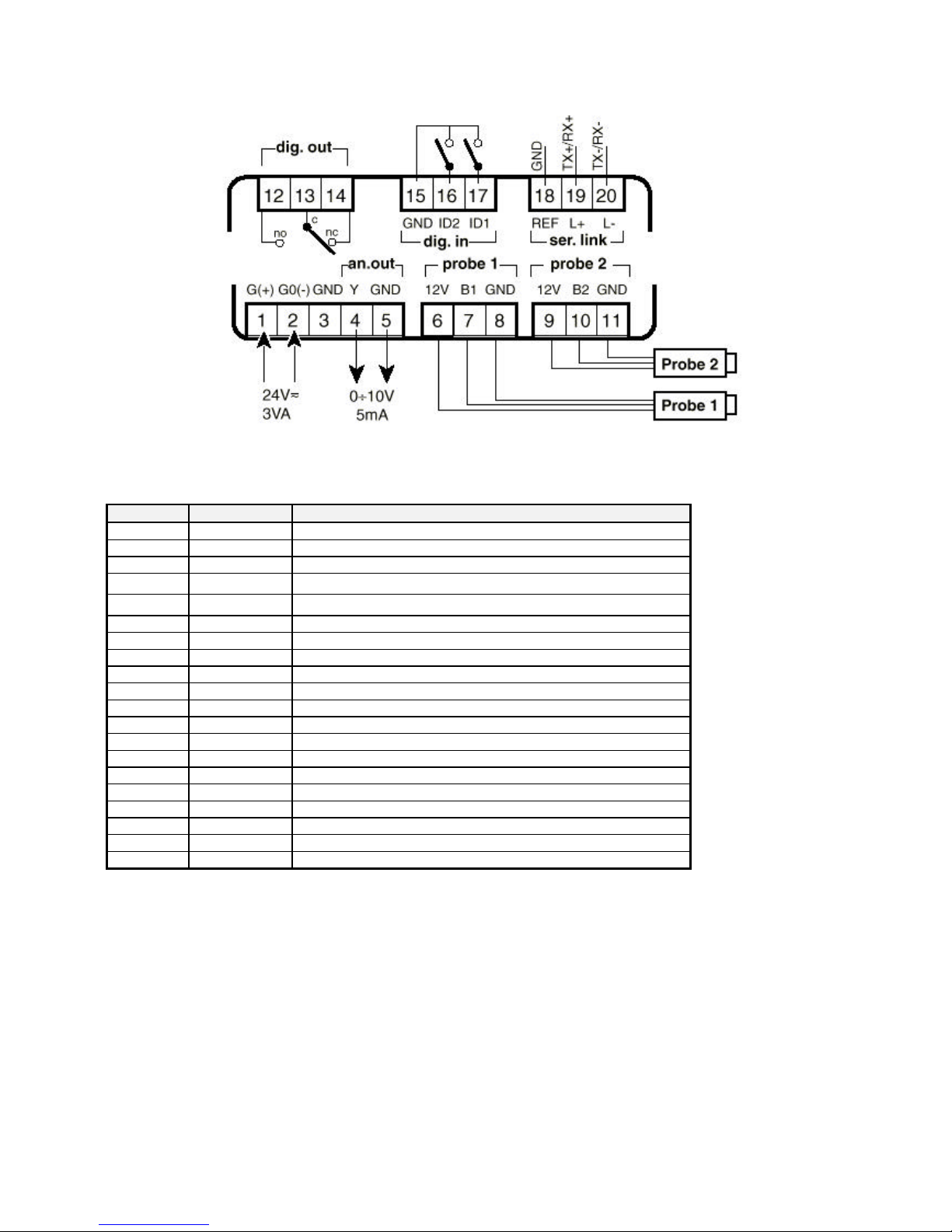
FCM electronic regulator - Preliminary version Cod. +302235300 - Rel. 2.0 del 30/11/98
33
12 Wiring diagram
12.1 Terminal block
Terminal Symbol Description
1 G(+) Power supply (positive pole when dc voltage)
2 G0(-) Power supply (negative pole when dc voltage)
3 GND Cable shielding
4 Y
0÷10Vdc analogue output
5 GND
GND for 0÷10Vdc analogue output
6 +12V Auxiliary power supply
7 B1 Input probe 1
8 GND GND for input probe 1
9 +12V Auxiliary power supply
10 B2 Input probe 2
11 GND GND for input probe 2
12 NO Relay output: normally open contact
13 C Relay output: common
14 NC Relay output: normally closed contact
15 GND Common for digital inputs
16 ID2 Digital input 2
17 ID1 Digital input 1
18 REF Serial line RS-485: reference
19 TX+/RX+ Serial line RS-485: positive pole
20 TX-/RX- Serial line RS-485: negative pole
Terminals G0(-) and GND are internally connected between them.
Terminal REF is internally connected to G0 and GND by a 22Ω resistance.
12.2 Power supply:
• • alternate voltage: half-wave rectification stage (should you use a dedicated transformer to power the regulator, keep into
consideration an increase - at least three times over - in heating due to the unbalance load of the rectifier).
• continuous voltage: polarity inversion will not damage the instrument but rather prevent it from functioning.
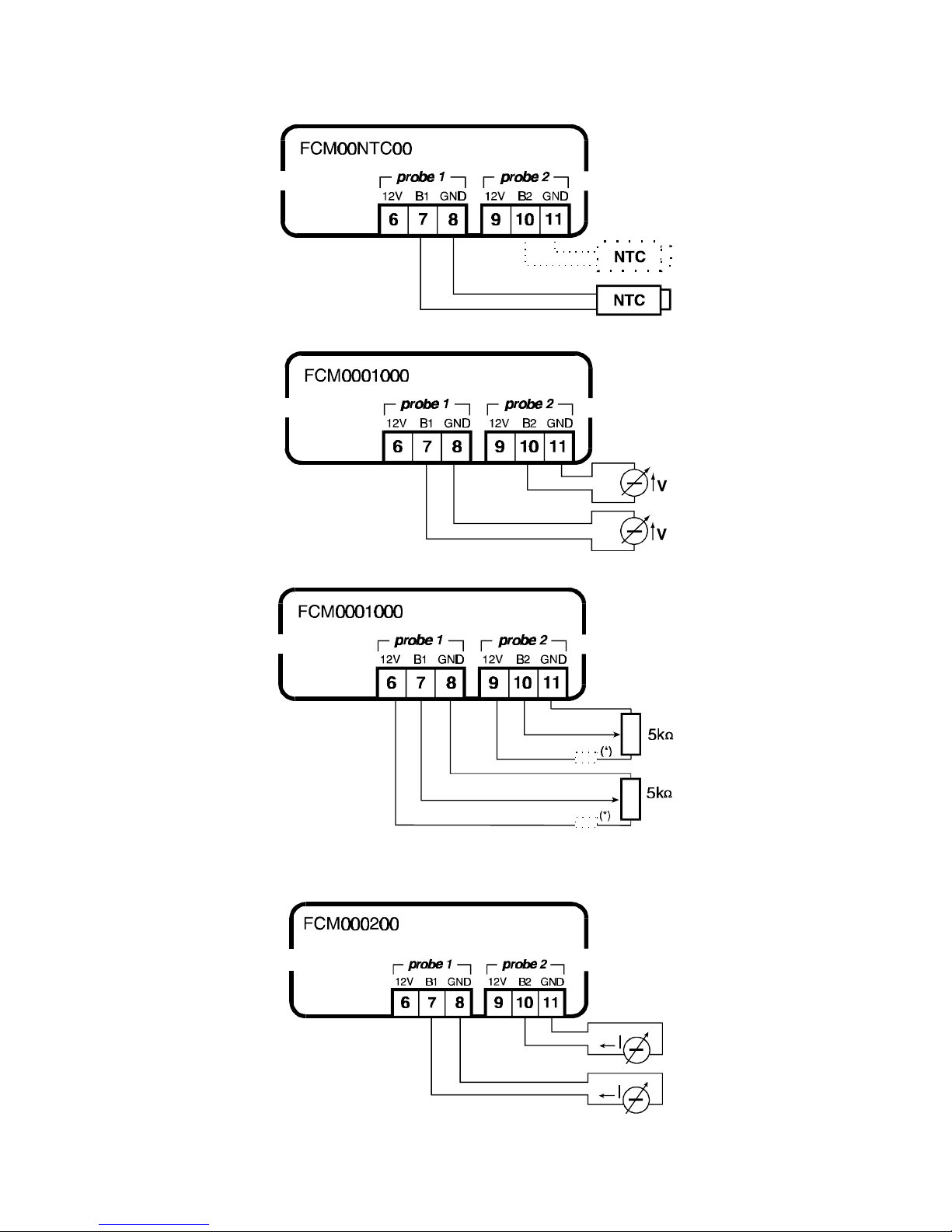
FCM electronic regulator - Preliminary version Cod. +302235300 - Rel. 2.0 del 30/11/98
34
12.3 Connecting probes
NTC Probes
Generator 0÷10 V probes
Potentiometer 0÷10 V probes (with separate external supply)
(*) It is recommended to connect an 820Ω resistor in series
Generator 0÷20mA o 4÷20mA probes (with separate external supply)
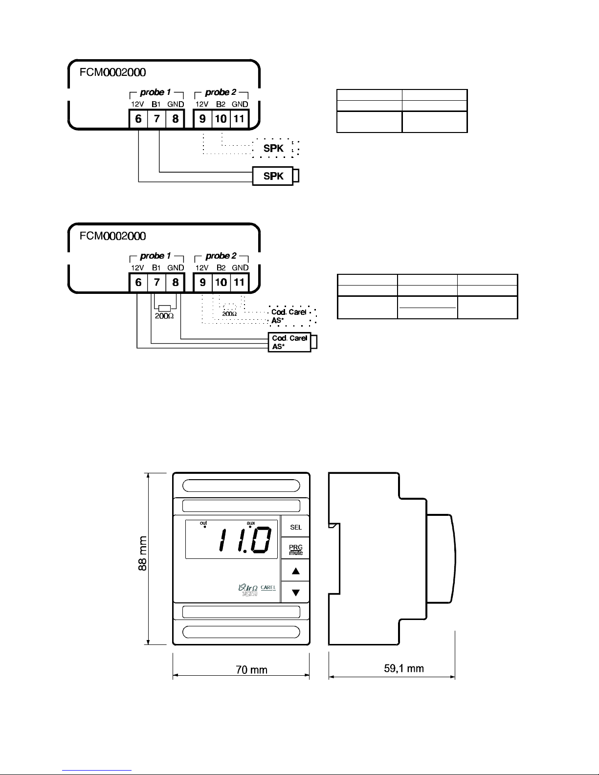
FCM electronic regulator - Preliminary version Cod. +302235300 - Rel. 2.0 del 30/11/98
35
SPK-type 0÷20mA o 4÷20mA SPK probes (Carel pressure probes)
0÷20mA or 4÷20mA AS* probes (Carel temperature/humidity active probes)
Note: using a probe, it is possible to inhibit the R200 Ω resistance connection, if the 7-B1 and 10-B2 terminals are bridged.
13 Dimensions
Carel reserves the right to modify the features of its products without prior notice.
6 7
9 10
+
BROWN
OUT
WHITE
9 10 11
6 7 8
+ (G) OUT H
OUT T
M
 Loading...