

Page 1

EVD mini
Superheat control for unipolar electronic
expansion valve
User manual
High Efficiency Solutions
NO POWER
& SIGNAL
CABLES
TOGETHER
READ CAREFULLY IN THE TEXT!
Page 2

Page 3

ENG
WARNINGS
CAREL bases the development of its products on decades of experience
in HVAC, on the continuous investments in technological innovations
to products, procedures and strict quality processes with in-circuit and
functional testing on 100% of its products, and on the most innovative
production technology available on the market. CAREL and its subsidiaries
nonetheless cannot guarantee that all the aspects of the product and the
software included with the product respond to the requirements of the final
application, despite the product being developed according to start-of-theart techniques. The customer (manufacturer, developer or installer of the final
equipment) accepts all liability and risk relating to the configuration of the
product in order to reach the expected results in relation to the specific final
installation and/or equipment. CAREL may, based on specific agreements, acts
as a consultant for the positive commissioning of the final unit/application,
however in no case does it accept liability for the correct operation of the final
equipment/system.
The CAREL product is a state-of-the-art product, whose operation is specified
in the technical documentation supplied with the product or can be
downloaded, even prior to purchase, from the website www.carel.com.
Each CAREL product, in relation to its advanced level of technology, requires
setup/configuration/programming/commissioning to be able to operate in
the best possible way for the specific application. The failure to complete such
operations, which are required/indicated in the user manual, may cause the
final product to malfunction; CAREL accepts no liability in such cases.
Only qualified personnel may install or carry out technical service on the
product.
The customer must only use the product in the manner described in the
documentation relating to the product.
In addition to observing any further warnings described in this manual, the
following warnings must be heeded for all CAREL products:
• prevent the electronic circuits from getting wet. Rain, humidity and all
types of liquids or condensate contain corrosive minerals that may damage
the electronic circuits. In any case, the product should be used or stored
in environments that comply with the temperature and humidity limits
specified in the manual;
• do not install the device in particularly hot environments. Too high
temperatures may reduce the life of electronic devices, damage them and
deform or melt the plastic parts. In any case, the product should be used
or stored in environments that comply with the temperature and humidity
limits specified in the manual;
• do not attempt to open the device in any way other than described in the
manual;
• do not drop, hit or shake the device, as the internal circuits and mechanisms
may be irreparably damaged;
• do not use corrosive chemicals, solvents or aggressive detergents to clean
the device;
• do not use the product for applications other than those specified in the
technical manual.
DISPOSAL
INFORMATION FOR USERS ON THE CORRECT
HANDLING OF WASTE ELECTRICAL AND ELEC-
TRONIC EQUIPMENT (WEEE)
In reference to European Union directive 2002/96/EC issued on 27 January
2003 and the related national legislation, please note that:
1. WEEE cannot be disposed of as municipal waste and such waste must be
collected and disposed of separately;
2. the public or private waste collection systems defined by local legislation must
be used. In addition, the equipment can be returned to the distributor at
the end of its working life when buying new equipment;
3. the equipment may contain hazardous substances: the improper use or
incorrect disposal of such may have negative effects on human health
and on the environment;
4. the symbol (crossed-out wheeled bin) shown on the product or on the
packaging and on the instruction sheet indicates that the equipment has
been introduced onto the market after 13 August 2005 and that it must
be disposed of separately;
5. in the event of illegal disposal of electrical and electronic waste, the penalties
are specified by local waste disposal legislation.
Warranty on the materials: 2 years (from the date of production, excluding
consumables).
Approval: the quality and safety of CAREL INDUSTRIES products are
guaranteed by the ISO 9001 certified design and production system, as well
as by the marks (*).
All of the above suggestions likewise apply to the controllers, serial boards,
programming keys or any other accessory in the CAREL product portfolio.
CAREL adopts a policy of continual development. Consequently, CAREL
reserves the right to make changes and improvements to any product
described in this document without prior warning.
The technical specifications shown in the manual may be changed without
prior warning.
The liability of CAREL in relation to its products is specified in the CAREL general
contract conditions, available on the website www.carel.com and/or by
specific agreements with customers; specifically, to the extent where allowed
by applicable legislation, in no case will CAREL, its employees or subsidiaries
be liable for any lost earnings or sales, losses of data and information, costs of
replacement goods or services, damage to things or people, downtime or any
direct, indirect, incidental, actual, punitive, exemplary, special or consequential
damage of any kind whatsoever, whether contractual, extra-contractual or
due to negligence, or any other liabilities deriving from the installation, use or
impossibility to use the product, even if CAREL or its subsidiaries are warned
of the possibility of such damage.
CAUTION: separate as much as possible the probe and digital input signal
cables from the cables carrying inductive loads and power cables to avoid
possible electromagnetic disturbance.
Never run power cables (including the electrical panel wiring) and signal
cables in the same conduits.
NO POWER
& SIGNAL
CABLES
TOGETHER
READ CAREFULLY IN THE TEXT!
3
“EVD mini” +0300036EN - rel. 1.2 - 23.04.2018
Page 4

Page 5

Content
1. INTRODUCTION 7
1.1 Models ............................................................................................................... 7
1.2 Functions and main characteristics .............................................................7
1.3 Accessories ....................................................................................................... 7
2. INSTALLATION 8
2.1 Dimensions and mounting-mm (in) .......................................................... 8
2.2 Description of the terminals ......................................................................... 9
2.3 Wiring diagram for superheat control ...................................................... 10
2.4 Installation ...................................................................................................... 10
2.5 Copy parameters with programming key ................................................ 11
3. USER INTERFACE 12
3.1 Keypad.............................................................................................................12
3.2 Display ............................................................................................................. 12
3.3 Programming mode .....................................................................................12
3.4 Restore factory parameters (default) ........................................................12
ENG
4. COMMISSIONING 13
5. FUNCTIONS 15
5.1 Control ............................................................................................................. 15
5.2 Analogue positioner (0-10 Vdc) ................................................................. 16
5.3 Superheat control with 2 temp. probes ................................................... 16
5.4 Special functions ............................................................................................17
5.5 Regolazione speciale: smooth lines ...........................................................17
5.6 Control parameters for protection functions .......................................... 18
5.7 Service parameters .......................................................................................18
6. PROTECTORS 19
6.1 Protectors ........................................................................................................ 19
7. PARAMETERS TABLE 21
8. NETWORK CONNECTION 23
8.1 RS485 serial configuration .......................................................................... 23
8.2 Network connection for commissioning via PC .....................................23
8.3 Visual parameter manager ..........................................................................23
8.4 Restore default parameters .........................................................................24
8.5 Setup by direct copy .....................................................................................24
8.6 Setup using configuration file ....................................................................25
8.7 Read the configuration file on the controller ..........................................25
8.8 Variables accessible via serial connection ...............................................26
8.9 Control states .................................................................................................27
8.10 Special control states ....................................................................................28
9. ALARMS 30
9.1 Types of alarms ..............................................................................................30
9.2 Probe alarms ..................................................................................................30
9.3 Control alarms ...............................................................................................30
9.4 Valve emergency closing procedure .........................................................30
9.5 Network alarm ............................................................................................... 31
9.6 Alarm table ..................................................................................................... 31
10. TROUBLESHOOTING 32
11. TECHNICAL SPECIFICATIONS 34
5
“EVD mini” +0300036EN - rel. 1.2 - 23.04.2018
Page 6

Page 7

1. INTRODUCTION
ENG
EVD mini is a range of drivers designed for the control of CAREL singlepole electronic expansion valves used in refrigerant circuits. EVD
mini controls refrigerant superheat and optimises refrigerant circuit
performance; it guarantees significant system flexibility being compatible
with various types of refrigerants, in applications with refrigerators and
chiller/air-conditioners. It features low superheat protection (LowSH), high
evaporation pressure (MOP) and low evaporation pressure (LOP) functions.
As regards network connectivity, the driver can be connected via serial
RS485/ Modbus® to:
• a pCO programmable controller
• a CAREL supervisor.
Another possibility involves operation as a simple positioner with 0 to 10
Vdc analogue input signal, or as a manual positioner via RS485. EVD mini
can be supplied with LED display for information on the instant superheat
value and any active alarms, or for performing the commissioning
operations. The latter involves setting just three parameters: refrigerant,
operating mode (showcase, air conditioner, etc.) and superheat set point.
The driver can also be setup using a computer via the serial port. In this
case, the VPM program (Visual Parameter Manager) needs to be installed,
downloadable from http://ksa.carel.com, and the USB-RS485 converter
connected.
1.1 Models
P/N Description
EVDM001N00 EVD mini 24 V with display
EVDM000N00 EVD mini 24 V without display
EVDM010N00 EVD mini 115/230 V without display
EVDM011N00 EVD mini 115/230 V with display
Tab. 1.a
1.2 Functions and main characteristics
In summary:
• superheat control with LowSH, MOP, LOP functions;
• compatibility with various types of refrigerants;
• guided setup procedures first, entering just three parameters on the
user interface: refrigerant (Gas), type of control (Mode) and superheat
set point (Superheat);
• activation/deactivation of control via digital input or remote control
via serial connection;
• controller and valve power supply incorporated (230 V/115 V);
• RS485 serial communication incorporated (Modbus protocol);
• IP65;
• operating conditions: -25T60C° (-13T140°F);
• compatible with Carel E2V and E3V single-pole valves.
From software revision 1.6 and higher, new functions have been
introduced:
• hot gas bypass by pressure;
• hot gas bypass by temperature.
The ratiometric pressure probe specified as default for assembly is P/N
SPKT0013P0, with an operating range from -1 to 9.3 barg. Alternatively,
other probes can be installed, setting the corresponding parameter
accordingly. See the “Functions” chapter..
P/N Type P/N Type
SPKT0053P0 -1…4.2 barg SPKT00B6P0 0…45 barg
SPKT0013P0 -1…9.3 barg SPKT00E3P0 -1…12.8 barg
SPKT0043P0 0…17.3 barg SPKT00F3P0 0…20.7 barg
SPKT0033P0 0…34.5 barg
Tab. 1.b
Single-pole valve (P/N E2V**F**C1/ E3V**B**C1)
Fig. 1.b
Ultracap module (P/N EVDMU**N**)
The module guarantees temporary power to the driver in the event of
power failures, for enough time to immediately close the connected
electronic valve. It avoids the need to install a solenoid valve. The module
is made using Ultracap storage capacitors, which ensure reliability in terms
of much longer component life than a module made with lead batteries.
Fig. 1.c
Ferrite (P/N 0907879AXX)
Clamp-on ferrite for use in certain applications. See the technical
specifications table.
Fig. 1.d
Programming key with power supply (P/N IROPZKEYA0)
The key can be used to quickly program the controllers, reducing the risk
of errors. This accessory also allows fast and effective technical service,
and can be used for programming the controllers in just a few seconds,
also during the testing phase.
The smooth lines function has been introduced starting from software
revision 1.8.
1.3 Accessories
Pressure probe cable (see technical leaflet +050000484), pressure
probe (-1…9.3 barg, P/N SPKT0013P0) and temperature probe (P/N
NTC006HP0R).
Fig. 1.a
Fig. 1.e
USB/RS485 converter (P/N CVSTDUMOR0)
The converter ensures connection between the computer used for
configuration and the EVD mini driver.
Fig. 1.f
7
“EVD mini” +0300036EN - rel. 1.2 - 23.04.2018
Page 8
ENG
2. INSTALLATION
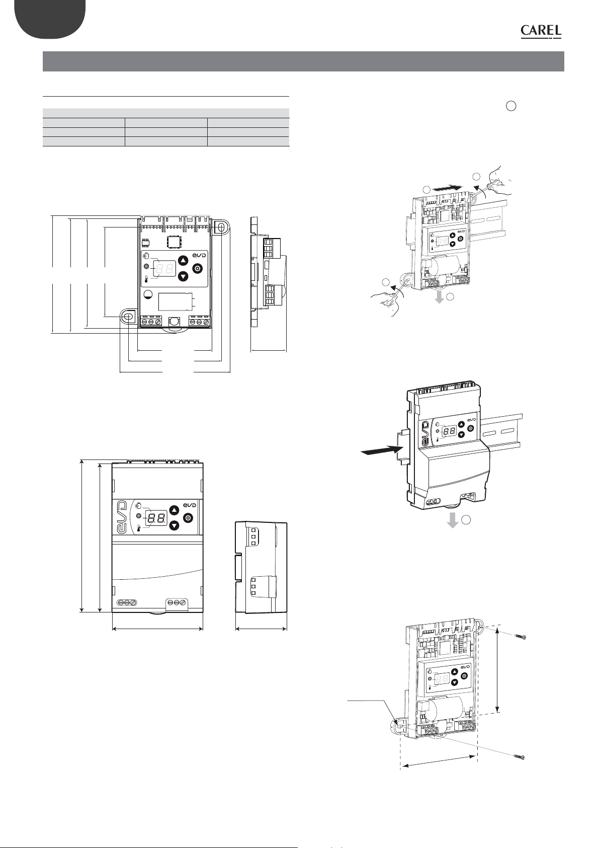
2.1 Dimensions and mounting-mm (in)
Mounting
EVD mini (24 V) YES YES
EVD mini (230 V) YES NO
95
(3.7)
87
(3.4)
72
(2.8)
98
(3.9)
on DIN rail: with screws
EVD mini (24 V)
GAS Type
Mode
Super Heat
BASSO/ BOTTOM
BASSO/ BOTTOM
60 (2.4)
74,1 (2.9)
88 (3.5)
33 (1.3)
On DIN rail mounting:
1. Fasten the DIN rail and fit the controller from point
2. 24V model: use a screwdriver to remove the two side slots before
installing any other controllers alongside.
EVD mini (24 V)
2
1
ype
T
GAS
Mode
t
a
Super He
2
A
Fig. 2.c
EVD mini (230 V)
A
;
117 (4.60)
113,7 (4.48)
Fig. 2.a
EVD mini (230 V)
GAS Type
Mode
Super Heat
70,7 (2.78)
Fig. 2.b
BASSO/ BOTTOM
42,7 (1.68)
Type
GAS
Mode
at
Super He
A
Fig. 2.d
Screw mounting
On the wall, mark the positions of the holes as per the figure and drill the
holes (Ø < 4mm). Then tighten the fastening screws.
GAS Type
Mode
t
Super Hea
72 (2.8)
Ø 4 (0.2)
“EVD mini” +0300036EN - rel. 1.2 - 23.04.2018
74,10 (2.9)
Fig. 2.e
8
Page 9

2.2 Description of the terminals
EVD mini 24 V EVD mini (230 V)
ENG
CAREL E2 V/ E3V
unipolar valve
0,3 Nm
A B C D
NTC
ULTRACAP
Module
3
ratiometric pressue
transducer
F
NTC
NTC
CAREL E2 V/ E3V
unipolar valve
0,3 Nm
A
E
1
Ferrite/ Ferrite bead
cod. 0907879AXX
+13V (in)
+13V (out)
GND
Signal
GND
S2
GAS Type
Mode
Super Heat
1
2
PC
VPM
CVSTDUM0R0
Modbus®
RS485
pCO
shield
GND
Tx/Rx+
Tx/Rx-
shield
G
G
G
H2
G
H1
S1
G0
G0
G0
24 Vac
GND
5Vref
DI
S2
Signal
digital input to start
the regulation
24 Vdc
20 VA
S2
230 Vac
S1
Ferrite/ Ferrite bead
cod. 0907879AXX
1
PC
VPM
CVSTDUM0R0
2
Modbus®
RS485
pCO
S1
shield
B
ULTRACAP
Module
3
1
GND
G
Tx/Rx+
C D
GAS Type
Mode
Super Heat
Tx/Rx-
shield
NTC
1
+13V (in)
+13V (out)
ratiometric pressue
transducer
E
S2
GND
Signal
GND
S2 S1
D I
N
the regulation
230 Vac
digital input to start
F
NTC
NTC
S2
S1
5Vref
GND
L
H3
S1
Signal
Fig. 2.f Fig. 2.a
Key:
Ref. Terminal Description Ref. Terminal Description
A
ExV Single-pole valve connection
+13 V (in)
+13 V (out) DI Digital input to enable control
B
Ultracap module connection (accessory)
GND
Signal S2 probe (temperature) N 230 V power supply, neutral
C
Ground Earth for S2 probe DI 230 V digital input to enable control
H2
(24 Vdc
power
supply)
H3
(230 V
power
supply)
GND Earth for S1 probe
D
G
G Power supply, 24 Vdc
G0 Power supply, 0 Vdc
L 230 V power supply, line
GND
Terminal for RS485 connection5Vref Power S1 active probe Tx/ Rx +
Signal S1 probe: pressure or temperature Tx/ Rx -
E
F
H1
(24 Vac
power
supply)
- Connection as positioner (0 to 10 V input)
-
Connection for superheat control with 2 temperatu-
re probes
G Power supply, 24 V ac
G0 Power supply, 0 V ac
DI Digital input to enable control
1
2
9
PC for configuration
USB – RS485 Converter
“EVD mini” +0300036EN - rel. 1.2 - 23.04.2018
Tab. 2.a
Page 10

ENG
2.3 Wiring diagram for superheat control
• EVD mini requires the use of an evaporation pressure probe S1 and
suction temperature probe S2, which will be fitted downstream of
the evaporator, and a digital input to enable control. Alternatively, the
signal to enable control can be sent via a remote RS485 connection;
• input S1 is programmable and connection to the terminals depends
on the parameter settings. See the chapters “Commissioning” and
“Functions”.
Note: for details on installing probes, see the “EEV system guide”
(+030220810).
CAREL E2 V/ E3V
unipolar valve
0,3 Nm
GAS Type
2 1
S2
S1
2.4 Installation
For installation, proceed as shown below, with reference to the wiring
diagrams and the technical specifications table:
1. connect the probes: these can be installed up to a maximum
distance of 10 m from the driver; select the pressure probe suitable
for the refrigerant. For details on the recommended pressure probe
for each refrigerant, see “Commissioning”;
2. connect any digital inputs, maximum length 10 m;
3. connect the valve cable: it is recommended to use a maximum cable
length of 1 m for E2V and E3V valves.
4. the 24 V models can be powered at:
• 24 Vac: use a class II safety transformer, adequately protected against
short-circuits and overload. Transformer power must be between
20 and 50 VA, as shown in the technical specifications table;
• 24 Vdc: use an external power supply, the see technical
specifications table;
5. the connection cables must have a minimum cross-section of 0.35 mm
6. power on the driver: the LED on the power supply/display comes
on and the driver will be immediately operational, with the default
parameters:
a. Refrigerant = R404A;
b. Type of control: multiplexed showcase/cold room;
c. Superheat set point = 11 K.
7. program the driver, if necessary: see the “User interface” chapter;
8. connect to the serial network where required. See the following diagrams
for connecting the earth on the 24 V EVD mini models.
EVD mini 24 Vac in serial network
Case 1: multiple drivers connected in a network, inside the same electrical
panel, powered by the same transformer
2
;
Mode
Super Heat
GND
Tx/Rx+
Tx/Rx-
PC
pCO
G
DI
GND
Tx/Rx+
Tx/Rx-
4
PC
VPM
5
CVSTDUM0R0
230 Vac
24 Vdc
20 VA
24 Vac
G0
Case 2: multiple drivers connected in a network, inside different electrical
3
digital input to start
the regulation
G
G0
G
G0
panels with the same earth point
GND
Tx/Rx+
Tx/Rx-
PC
pCO
Important: Earthing of G0 and G in driver EVD mini 24 Vac
G
DI
G0
GND
Tx/Rx+
Tx/Rx-
Fig. 2.h
G
DI
G0
24 Vac
20 VA
GND
Tx/Rx+
Tx/Rx-
Fig. 2.i
230 Vac
G
DI
G0
24 Vac
G
DI
G0
24 Vac
230 Vac
230 Vac
20 VA
connected in serial network brings to permanent damage of the driver.
Fig. 2.g
Key:
Ratiometric pressure transducer – evaporation pressure
1
NTC – suction temperature
2
Digital input to enable control
3
Personal computer for configuration
4
USB / tLAN converter
5
“EVD mini” +0300036EN - rel. 1.2 - 23.04.2018
10
G
G
DI
GND
Tx/Rx+
Tx/Rx-
PC
pCO
G0
24 Vac
20 VA
GND
Tx/Rx+
Tx/Rx-
230 Vac
G0
24 Vac
DI
NO!
230 Vac
20 VA
Fig. 2.j
Page 11
ENG
Installation environment
Important: avoid installing the drivers in environments with the
following characteristics:
• relative humidity greater than 90% or with condensation;
• strong vibrations or knocks;
• exposure to continuous water sprays;
• exposure to aggressive and polluting atmospheres (e.g.: sulphur
and ammonia fumes, saline mist, smoke) to avoid corrosion and/or
oxidation;
• strong magnetic and/or radio frequency interference (therefore avoid
installing the devices near transmitting antennae);
• exposure of the driver to direct sunlight and to the elements in general.
Important: the following warnings must be observed when
connecting the driver:
• if the driver is used in a way that is not specified in this user manual,
protection cannot be guaranteed;
• incorrect power connections may seriously damage the driver;
• use cable ends suitable for the corresponding terminals. Loosen each
screw and insert the cable ends, then tighten the screws and gently
tug the cables to check they are sufficiently tight;
• separate as much as possible (at least 3 cm) the probe and digital
input cables from power cables to avoid possible electromagnetic
disturbance. Never run power cables (including the electrical panel
cables) and probe signal cables in the same conduits;
• do not run probe signal cables in the immediate vicinity of power
devices (contactors, circuit breakers, etc.). Reduce the path of probe
cables as much as possible, and avoid spiral paths that enclose power
devices;
• avoid powering the controller directly from the main power supply in
the panel if this supplies different devices, such as contactors, solenoid
valves, etc., which will require a separate transformer;
• *EVD mini/ice is a controller to be incorporated into the final
equipment; it must not be wall-mounted;
• * DIN VDE 0100: protective separation must be guaranteed between
the SELV circuits (Safety Extra Low Voltage) and the other circuits. The
requirements of DIN VDE 0100 must be complied with. To prevent
disruption of the protective separation (between the SELV circuits and
the other circuits) ensure additional fastening near the terminations.
This additional fastening must secure the insulation and not the wires.
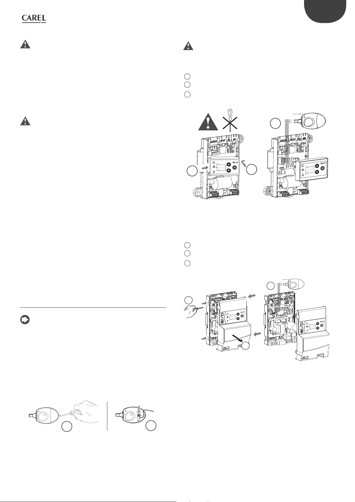
EVD mini (24 V)
Important: do not use a screwdriver to remove the cover on the
display, to avoid damaging the board.
To remove the cover of the display:
Apply a pressure rightward on the left side of the cover.
1
Raise up the right side to extract it.
2
Plug the key into the provided connector, then perform the desired
3
operation (UPLOAD/DOWNLOAD).
L
3
GAS Type
press
Mode
1
Super Heat
EVD mini (230 V)
To remove the cover of the display:
Press with a screwdriver as shown in the figure, to remove the cover.
1
Lift the cover and remove it.
2
Plug the key into the provided connector, then perform the
3
desired operation (UPLOAD/DOWNLOAD).
press
2
Fig. 2.l
GAS
Mode
Super Heat
L
3
ype
T
2.5 Copy parameters with programming key
Note:
• The parameters must only be copied when the driver is NOT powered;
• also see the programming key technical leaflet, P/N +050003930.
Procedure:
A. Open the cover on the key using a screwdriver;
B. Set the microswitches based on the operation :
- UPLOAD: microswitches 2 = OFF,
- DOWNLOAD: microswitches 1= OFF,
microswitches 2 = ON
See leaflet +050003930
A
Fig. 2.k
B
1
press
ype
GAS T
Mode
t
a
Super He
press
ype
T
GAS
Mode
Super Heat
2
Fig. 2.m
11
“EVD mini” +0300036EN - rel. 1.2 - 23.04.2018
Page 12

ENG
3. USER INTERFACE
On models where featured, the user interface comprises the twodigit display and keypad with three buttons that, pressed alone or in
combination, are used to perform all the configuration and programming
operations on the driver.
Model without display
1
2
Fig. 3.a
1
Red LED - see “Alarms”
2
Green LED - power supply ON
Model with display
2
GAS Type
Mode
Super Heat
12
3
1
4
Fig. 3.b
Key
1
Parameter label (for commissioning)
2
Keypad
3
Control ON/OFF digital input status LED
4
flashing/off = DI closed/open (*)
Two-digit display
(*) when the digital input is closed, the LED flashes and control is activated.
During commissioning/setup, the parameter label shows the meaning
of the segments displayed in the first digit, corresponding to the three
parameters being set:
A. GAS Type: type of refrigerant;
B. Mode: operating mode;
C. Superheat: superheat set point.
See the “Commissioning” chapter.
Mode
GAS Type
Super Heat
GAS Type
Mode
Super Heat
GAS Type
Mode
Super Heat
A. Refrigerant B. Mode (operating mode) C. Superheat set point
3.1 Keypad
Key Description
/
UP DOWN
PRG/Set
• Increases/decreases the value of the set point or other
selected parameter
• menu navigation
• at the end of the commissioning procedure, press for 2 s to
exit and activate control;
• enter/exit control mode, saving the parameters;
• reset alarm E8
Tab. 3.b
3.2 Display
During normal operation, the two-digit display shows the superheat
measure and any alarms. If used as an analogue positioner, it displays
the 0 to 10 V input value with decimal point. The display interval for the
superheat value is -5 to 55 K (-9 to 99 °F). In general, values between -99
and 999 are displayed as follows:
1. values from 0 to 10 are displayed with decimal point and decimals;
2. values greater than 99 are displayed in two steps:
- first, the hundreds, followed by “H”
- then the tens and units.
“EVD mini” +0300036EN - rel. 1.2 - 23.04.2018
3. values less than -9 are displayed in two steps:
- first the “-“sign;
- then the tens and units.
123 --->
-99 --->
GAS Type
Mode
Super Heat
GAS Type
Mode
Super Heat
GAS Type
Mode
Super Heat
GAS Type
Mode
Super Heat
Fig. 3.c
3.3 Programming mode
The parameters can be modified using the front keypad. Access depends
on the user level: basic parameters (first configuration/setup) and Service
parameters (Installer).
Important: DO NOT change the control parameters before
completing the commissioning wizard, as described in chapter 4.
Modifying the Service parameters
The Service parameters include, in addition to the parameters for the
configuration of input S1, those corresponding to the network address,
probe readings, protectors and manual positioning. See the param. table.
Procedure:
1. press UP and DOWN together and hold for more than 5 s: the first
parameter is displayed: P1 = probe S1 reading;
2. press UP/ DOWN until reaching the desired parameter;
3. press PRG/ Set to display the value;
4. press UP/ DOWN to modify the value;
5. press PRG/ Set to confirm and return to the parameter code;
6. repeat steps 2 to 5 to modify other parameters;
7. (when the parameter code is displayed) press PRG/Set and hold for
more than 2 s to exit the parameter setting procedure.
GAS Type
Mode
Super Heat
Fig. 3.d
Note: if no button is pressed, after around 30 s the display
automatically returns to standard visualisation.
3.4 Restore factory parameters (default)
It is possible restore the controller to the default settings.
Procedure:
with the controller in standard display mode, press the
three buttons together. After 5 seconds the display shows “rS”. The reset
procedure can
be confirmed within 10 seconds, by pressing PRG/SET buttons
for 3 seconds. If no button is pressed during this time, the procedure will
be cancelled. At the end, the controller displays two dashes and then
awaits the commissioning parameters.
12
Page 13

4. COMMISSIONING
ENG
Note:
• If the controller does not have a display, see “Network connection”;
• the default pressure probe is the ratiometric probe, with a measurement
range of -1…9.3 barg;
• note the unit of measure (K/°F) when setting the superheat set point. To
change the unit of measure, see the “Functions” chapter.
4.1 Commissioning procedure
Once the electrical connections have been completed (see the chapter
“Installation”) and the power supply has been connected, the operations
required for commissioning the driver depend on the type of interface
used, however essentially involve setting just 3 parameters: refrigerant,
functioning mode, superheat setpoint.
Important:
• until the commissioning procedure has been completed, control will
not be active;
• (only during commissioning) changing the refrigerant also means
having to change the type of pressure probe.
Power on the driver: the display lights up and the driver awaits the
commissioning parameters, as indicated by the bar on the display:
1. Refrigerant (default = 3: R404A);
2. Type of control (default = 1: multiplexed showcase/cold room);
3. Superheat set point (default= 11 K).
Procedure:
4. Press PRG to save the setting and return to the refrigerant parameter
code (bar at top)
GAS Type
Mode
Super Heat
5. Press DOWN to move to the next parameter: Mode, indicated by the
bar in the middle.
6. Repeat steps 2-4 to set superheat settings 1-7 and bypass 8-9;
GAS Type
Mode
Super Heat
7. Press DOWN to move to the next parameter. For the superheat set
point, the bar at the bottom is shown. Set the superheat set point;
GAS Type
GAS Type
Mode
Super Heat
1. The display shows the bar at the top: refrigerant (GAS Type)
GAS Type
Mode
Super Heat
2. Press PRG/Set to display the refrigerant setting
GAS Type
Mode
Super Heat
3. Press UP/DOWN to modify the value
GAS Type
Mode
Super Heat
8. In the event of bypass control by pressure, parameter _P is shown.
Set the bypass pressure set point.
GAS Type
Mode
Super Heat
9. In the event of bypass control by temperature, parameter _t is
shown. Set the bypass temperature set point.
GAS Type
Mode
Super Heat
10. Press PRG/Set for 2 s to save the settings, exit programming mode
and activate control. The standard display is shown.
Mode
Super Heat
13
“EVD mini” +0300036EN - rel. 1.2 - 23.04.2018
Page 14
ENG
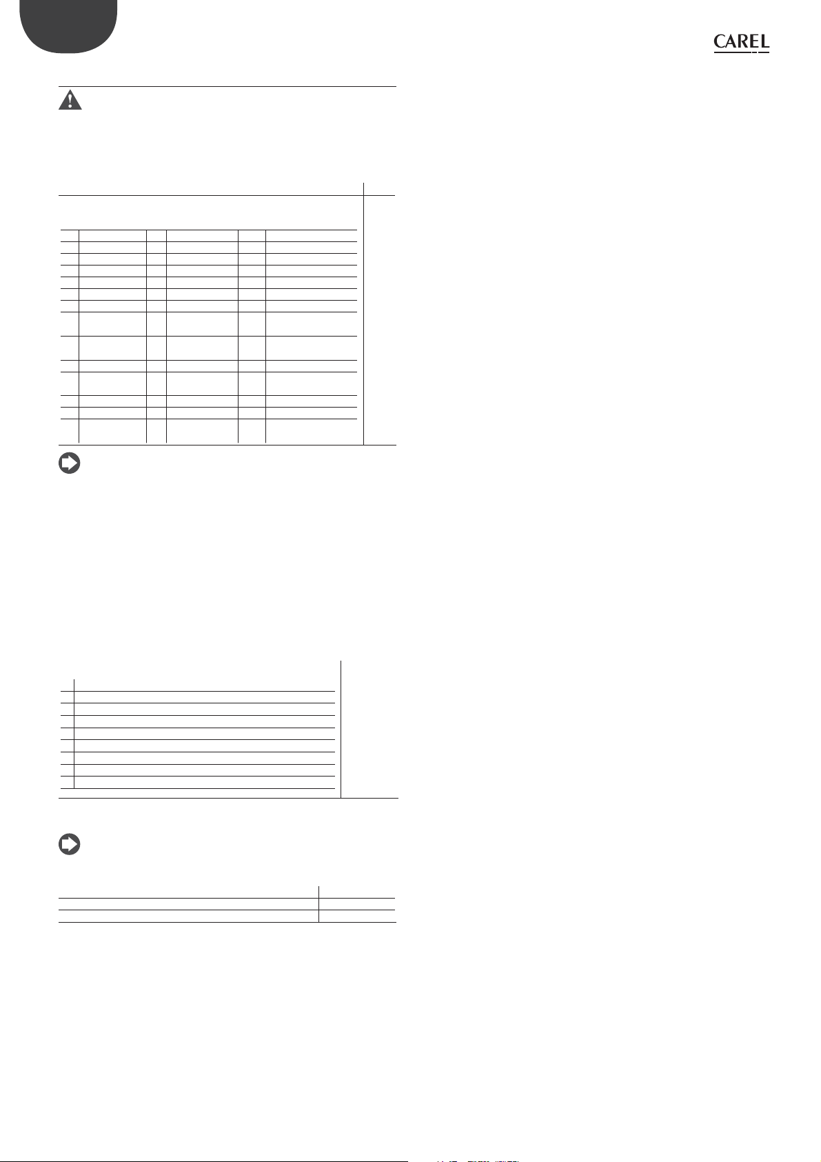
4.5 Initial configuration parameters
Important: ONLY DURING COMMISSIONING, changing the
refrigerant also means having to change the type of ratiometric probe;
if not specified in the table, the ratiometric probe type is (-1 ... 9.3 barg).
Refrigerant
Parameter/ description Def.
Gas Type = refrigerant
0 = Custom
1 R22 15 R422D 29 R455A (-1...12.8 barg)
2 R134a 16 R413A 30 R170 (0...17.3 barg)
3 R404A 17 R422A 31 R442A (-1...12.8 barg)
4 R407C 18 R423A 32 R447A (-1...12.8 barg)
5 R410A 19 R407A 33 R448A
6 R507A 20 R427A 34 R449A
7 R290 21 R245FA 35 R450A (-1...4.2 barg)
8 R600
(-1...4.2 barg)
9 R600a
(-1...4.2 barg)
10 R717 24 HTR01 38 R452B
11 R744
(0...45 barg)
12 R728 26 R23 40 R454B
13 R1270 27 R1234yf
14 R417A 28 R1234ze (-1...4.2
22 R407F 36 R452A (-1...12.8 barg)
23 R32
(0...17.3 barg)
25 HTR02 39 R513A (-1...4.2 barg)
barg)
37 R508B (-1...4.2 barg)
3 =
R404A
Note: if the refrigerant gas is not among those selectable for the
“GAS Type = refrigerant” parameter:
1. set any refrigerant (e.g. R404);
2. select the type of main control, the superheat set point and complete
the initial commissioning procedure;
3. use the VPM program (Visual Parameter Manager, see the chapter
“Network connection”) and set the type of refrigerant: “0 = custom”
and the “Dew point a...f high/low” parameters that define the
refrigerant;
4. start control, for example by closing the digital input contact.
Operating mode
Mode = Operating mode
1 Multiplexed showcase/cold room
2 Air-conditioner/chiller with plate heat exchanger
3 Air-conditioner/chiller with tube bundle heat exchanger
4 Air-conditioner/chiller with finned coil heat exchanger
5 Analogue positioner (0 to 10 V)
6 Superheat control with 2 temperature probes
7 Subcritical CO2 showcase/cold room
8 Hot gas bypass by pressure
9 Hot gas bypass by temperature
1 = Multiplexed
showcase/
cold room
Set point
Note: take into consideration the unit of measure (K/°F) when
setting the superheat set point.
Superheat set point 11 K(20°F)
Bypass pressure set point 3 bar
Bypass temperature set point 10 °C
“EVD mini” +0300036EN - rel. 1.2 - 23.04.2018
14
Page 15

5. FUNCTIONS
5.1 Control
EVD mini is a superheat controller and can be used as an analogue
positioner. The type of refrigeration unit can be selected using the
“Operating mode” parameter.
ENG
Parameter/description Def.
Operating mode
1 Multiplexed cabinet/cold room
2 Air-conditioner/chiller with plate heat exchanger
3 Air-conditioner/chiller with tube bundle heat exchanger
4 Air-conditioner/chiller with finned coil heat exchanger
5 Analogue positioner (0 to 10 V)
6 Superheat control with 2 temperature probes
7 Subcritical CO2 showcase/cold room
8 Hot gas bypass by pressure
9 Hot gas bypass by temperature
1 = multiplexed
cabinet/cold room
Tab. 5.a
Based on the operating mode setting , the driver automatically sets a
series of control parameters.
Operating mode PID:
1 Multiplexed cabinet/cold room 15 150 11 5 15 -50 0 50 20
2 Air-conditioner/chiller with plate heat exchanger 3 40 6 2 2,5 -50 4 50 10
3 Air-conditioner/chiller with tube bundle heat
exchanger
4 Air-conditioner/chiller with finned coil heat
exchanger
5 Analogue positioner (0 to 10 V) - - - - - - - - 6 Superheat control with 2 temperature probes 15 150 11 5 15 -50 0 50 20
7
Subcritical CO2 showcase/cold room
8
Hot gas bypass by pressure
9
Hot gas bypass by temperature
proport.
gain
5 60 6 2 2,5 -50 4 50 10
10 100 6 2 10 -50 10 50 20
20 400 13 7 15 -50 0 50 20
PID:
integration time
20 200 - - - - - - - 3 15 150 - - - - - - - - 10
Superheat
set
point
LowSH protection
th-
Integra-
reshold
tion time
LOP protection MOP protection Bypass
threshold
Integration time
threshold
Integration time
pres-
sione:
setpoint
(bar)
Bypass
tempe-
ratura:
setpoint
(°C)
Tab. 5.b
Superheat
The primary purpose of the electronic valve is ensure that the flow-rate
of refrigerant that flows through the nozzle corresponds to the flow-rate
required by the compressor. In this way, the evaporation process will take
place along the entire length of the evaporator and there will be no liquid
at the outlet (consequently in the branch that runs to the compressor). As
liquid is not compressible, it may cause damage to the compressor and even
breakage if the quantity is considerable and the situation lasts some time.
Superheat control
The parameter that the control of the electronic valve is based on is
the superheat temperature, which effectively tells whether or not there
is liquid at the end of the evaporator. The superheat temperature is
calculated as the difference between: superheated gas temperature
(measured by a temperature probe located at the end of the evaporator)
and the saturated evaporation temperature (calculated based on the
reading of a pressure transducer located at the end of the evaporator and
using the Tsat(P) conversion curve for each refrigerant).
(*)
Superheat = Superheated gas temperature
temperature
(*) suction
If the superheat temperature is high it means that the evaporation
process is completed well before the end of the evaporator, and therefore
flow-rate of refrigerant through the valve is insufficient. This causes a
reduction in cooling efficiency due to the failure to exploit part of the
evaporator. The valve must therefore be opened further.
– Saturated evaporation
The valve must therefore be closed further. The operating range of the
superheat temperature is limited at the lower end: if the flow-rate through
the valve is excessive the superheat measured will be near 0 K. This indicates
the presence of liquid, even if the percentage of this relative to the gas
cannot be quantified. There is therefore un undetermined risk to the
compressor that must be avoided. Moreover, a high superheat temperature
as mentioned corresponds to an insufficient flow-rate of refrigerant. The
superheat temperature must therefore always be greater than 0 K and have
a minimum stable value allowed by the valve-unit system.
A low superheat temperature in fact corresponds to a situation of probable
instability due to the turbulent evaporation process approaching the
measurement point of the probes. The expansion valve must therefore
be controlled with extreme precision and a reaction capacity around
the superheat set point, which will almost always vary from 3 to 14 K.
Set point values outside of this range are quite infrequent and relate to
special applications.
Vice-versa, if the superheat temperature is low it means that the evaporation
process has not concluded at the end of the evaporator and a certain quantity
of liquid will still be present at the inlet to the compressor.
15
“EVD mini” +0300036EN - rel. 1.2 - 23.04.2018
Page 16

ENG
C
L
S2
F
S
EV
M
V
EVD mini
S1
T
E
CP
T
Fig. 5.a
Key
CP compressor EEV electronic expansion valve
C condenser V solenoid valve
L liquid receiver E evaporator
F dewatering filter P pressure probe (transducer)
S liquid indicator T temperature probe
For the wiring, see “Wiring description”.
PID parameters
Superheat control uses a PID algorithm. The control output is calculated
as the sum of separate contributions: proportional and integral.
• the proportional action opens or closes the valve proportionally to
the variation in the superheat temperature. Thus the greater the K
(proportional gain) the higher the response speed of the valve. The
proportional action does not consider the superheat set point, but
rather only reacts to variations. Therefore if the superheat value does
not vary significantly, the valve will essentially remain stationary and
the set point cannot be reached;
• the integral action is linked to time and moves the valve in proportion
to the deviation of the superheat value from the set point. The greater
the deviations, the more intense the integral action; in addition, the
lower the value of Ti (integral time), the more intense the action
will be. The integral time, in summary, represents the intensity of the
reaction of the valve, especially when the superheat value is not near
the set point.
See the “EEV system guide” +030220810 for further information on
calibrating PID control.
5.2 Analogue positioner (0-10 Vdc)
The valve will be positioned linearly depending on the value of the “0
to 10 V input for analogue valve positioning” read by input S2. There
is no PID control nor any protection (LowSH, LOP, MOP), and no valve
unblock procedure. The opening of digital input DI stops control, and
consequently forces the valve closed, switching operation to standby.
0 ...10 Vdc
EV
S2
S1
EVD mini
A
100%
0%
010
regulator
Vdc
Fig. 5.b
Key:
EV Electronic valve A Valve opening
For the wiring see chap. 2: “Description of the terminals”.
Important: the pre-positioning and re-positioning procedures will
not be performed. Manual positioning can in any case be enabled when
control is active or in standby.
T
P
5.3 Superheat control with 2 temp. probes
The functional diagram is shown below. This type of control must be used
with care, due to the lower precision of the temperature probe compared
to the probe that measures the saturated evaporation pressure.
Parameter/ description Def.
Mode = Operating mode
… 6 = Superheat control with 2 temperature
probes
1 = Multiplexed showcase/
cold room
C
Par. Description Def. Min. Max. UoM
Superheat Superheat set point
CP
ti
PID proport. gain 15 0 800 PID integral time 150 0 999 s
LowSH: threshold 55 (99) K(°F)
11(20)
Note: when selecting the type of Mode, the PID control values
suggested by CAREL will be automatically set for each application.
Control parameters for protection functions
See chapter on “Protectors”.
“EVD mini” +0300036EN - rel. 1.2 - 23.04.2018
L
S2
F
S
EV
M
V
EVD mini
S1
T
E
T
Fig. 5.e
Key:
CP Compressor V Solenoid valve
C Condenser S Liquid indicator
L Liquid receiver EV Electronic valve
F Dewatering filter E Evaporator
T Temperature probe S1 Evaporation temperature probe
S2 Suction temperature probe
For the wiring see chap. 2: “Description of the terminals”.
16
CP
Page 17

ENG
Par. Description Def Min Max UOM
Superheat Superheat set point 11(20) LowSH:
CP PID: proportional gain 15 0 800 ti PID: integral time 150 0 999 s
55(99) K
thresh.
5.4 Special functions
Hot gas bypass by pressure
This function can be used for cooling capacity control. If there is no
request from circuit B, the compressor suction pressure decreases and
the bypass valve opens, so as to deliver more hot gas and decrease circuit
capacity.
C
L
EV
F
S
M T
A
V1 V2
M T
B
EVD mini
E
E
S2
S1
CP
P
Hot gas bypass by temperaturs
This function can be used for cooling capacity control. On a showcase, if
the room temperature probe detects an increase in temperature, cooling
capacity needs to increase, so the valve must close.
C
LEV
S2
EVD mini
T
S1
CP
F
S
M T
V1 V2
E
Key
CP compressor V1 solenoid valve
C condenser V2 thermostatic expansion valve
L liquid receiver EV electronic valve
F filter-drier E evaporator
S liquid sightglass
For the wiring see the “General connection diagram”.
This is PID without any protection (LowSH, LOP, MOP, see the chapter
on Protectors), no valve unblock procedure and no auxiliary control
functions. The function uses the hot gas bypass temperature probe
read by input S2, compared against the “Hot gas bypass temperature set
point”. Control is reverse: as the temperature increases, the valve closes
and vice-versa.
V1 V2
Key
CP compressor V1 solenoid valve
C condenser V2 thermostatic expansion valve
L liquid receiver EV electronic valve
F filter-drier E evaporator
S liquid sightglass
For the wiring see the “General connection diagram”.
This is PID without any protection (LowSH, LOP, MOP, see the chapter
on Protectors), no valve unblock procedure and no auxiliary control
functions. The function uses the hot gas bypass pressure probe read
by input S1, compared against the “Hot gas bypass pressure set point”.
Control is reverse: as the pressure increases, the valve closes and viceversa.
Par. Description Def Min Max UOM
_P Hot gas bypass pressure
set point
CP PID: proportional gain 15 0 800 ti PID: integral time 150 0 999 s
3 -20(290) 200(2900) bar(psig)
Par. Description Def Min Max UOM
_t Hot gas bypass tempera-
ture set point
CP PID: proportional gain 15 0 800 ti PID: integral time 150 0 999 s
10 -85(-121) 200(392) °C(°F)
5.5 Special control function: smooth lines
Note: the Smooth_line parameter is only accessible via the
supervisor.
The smooth lines function optimises evaporator capacity based on actual
cooling demand, allowing more effective and stable control. The function
completely eliminates traditional on/off control cycles, modulating the
temperature exclusively using the electronic valve; superheat set point
is controlled through a precise PI control algorithm based on the actual
control temperature.
The master controller (connected via serial to EVD mini), through
dynamic management of the Smooth_line parameter, modifies the
superheat set point for management of the electronic expansion valve,
from a minimum (SH_SET) to a maximum (SH_SET + Smooth_line): this
consequently acts directly on the PID control algorithm that modifies the
valve position. This is useful when the control temperature approaches
the set point; the Smooth_line parameter is used to prevent the valve
from closing, by reducing the evaporator’s cooling capacity.
In order to use this function, the digital input must be configured as
BACKUP. The Smooth_line parameter thus allows the control set point to
be adjusted instantly.
In the event where there is no network connection, the Smooth_line
parameter is reset so as to resume normal control (START/STOP from
digital input and SH_SET as the superheat set point).
17
“EVD mini” +0300036EN - rel. 1.2 - 23.04.2018
Page 18

ENG
The main effects are:
• no swings in temperature and superheat due to the set point being
reached;
• stable temperature and superheat control;
• maximum energy savings due to load stabilisation.
Par. Description Def. Min. Max. UOM
di
Smooth_line
Key
SH set Superheat set point t time
Temp.set Temperature set point
Note: the temperature setting based on the corresponding set
point is managed by the master controller, while superheat control is
managed by the EVD mini.
DI configuration
1=start/stop - 2=control backup
A: superheat set point offset for
smooth lines
SH_set+
Smooth_line
SH set
Temp. set
11 2 -
0 -99
(-55)99(55)
K/°F
t
t
5.6 Control parameters for protection
functions
See chapter on “Protectors”.
5.7 Service parameters
The other configuration parameters, to be set where necessary before
starting the controller, concern:
• the type of ratiometric pressure/temperature probe;
• the serial address for network connection;
• the type of unit of measure;
• enabling change in type of control (Mode);
• the number of steps (480/960) to control valve position.
Type of pressure/temperature probe (par. S1)
S1 is used to select the type of ratiometric pressure or NTC probe.
Par. Description Def. Min. Max. UOM
S1 Type of probe S1
1 = -1…4.2 barg
2 = 0.4…9.3 barg
3 = -1…9.3 barg
4 = 0…17.3 barg
5 = 0.85…34.2 barg
6 = 0…34.5 barg
7 = 0…45 barg
8 = -1…12.8 barg
9 = 0…20.7 barg
10 = 1.86…43.0 barg
11 = NTC (-50…105°C)
12 = Ratiometric (OUT=0-5V ) 0-60 barg
13 = Ratiometric (OUT=0-5V) 0-90 barg
14 = Remote pressure probe from RS485
3111-
Network address (par. n1)
See chap. “Network connection”
Unit of measure (par. Si)
The unit of measure used by the driver can be selected:
• S.I. (°C, K, barg);
• Imperial (°F, psig).
Par. Description Def. Min. Max. UOM
Si Unit of measure
1=°C/K/barg
2=°F/psig
Note: lthe unit of measure K or °F relates to degrees Kelvin or
Fahrenheit adopted for measuring the superheat and the related
parameters.
When changing the unit of measure, all the values of the parameters
saved on the driver and all the measurements read by the probes will
be recalculated. This means that when changing the units of measure,
control remains unaltered.
Example 1: The pressure read is 20 barg, this will be immediately
converted to the corresponding value of 290 psig.
Example 2: The “superheat set point” parameter set to 10 K will be
immediately converted to the corresponding value of 18 °F.
112-
Access to Mode parameter (par. IA)
To avoid accidental modification of the controller’s operating mode, it
is possible to disable the access to the corresponding mode parameter
(mode).
Par. Description Def. Min. Max. UOM
IA Enable operating mode modification
0/1 = yes/ no
001-
Number of control steps (par. U3)
Total number of steps between the valve fully closed and fully open
position
Par. Description Def. Min. Max. UOM
U3 Number of valve control steps
1 / 2 = 480/960 steps
112-
Digital input
The digital input function can be set by parameter:
Par. Description Def. Min. Max. UOM
di DI configuration
1=Start/stop control;
2=Control backup
Start/Stop control:
• digital input closed: control activated;
• digital input open: driver in standby (see paragraph “Control status”);
Important: this setting excludes activation/deactivation of control
from the network. See the next setting.
Control backup: when connected to a network, in the event of
communication failures, the driver verifies the status of the digital input
to determine whether control is activated or in standby.
112-
Note: the maximum and minimum limits for the pressure probe
alarm can be set. See the parameter table.
“EVD mini” +0300036EN - rel. 1.2 - 23.04.2018
18
Page 19

6. PROTECTORS
ENG
These are additional functions that are activated in specific situations that
are potentially dangerous for the unit being controlled. They feature an
integral action, that is, the action increases gradually when moving away
from the activation threshold. They may add to or overlap (disabling)
normal PID superheat control. By separating the management of these
functions from PID control, the parameters can be set separately, allowing,
for example, normal control that is less reactive yet much faster in
responding when exceeding the activation limits of one of the protectors.
6.1 Protectors
The protectors are 3:
• LowSH, low superheat;
• LOP, low evaporation temperature;
• MOP, high evaporation temperature;
The protectors have the following main features:
• activation threshold: depending on the operating conditions of the
controlled unit, this is set in Service programming mode;
• integration time, which determines the intensity (if set to 0, the
protector is disabled): set automatically based on the type of main
control;
• alarm, with activation threshold (the same as the protector) and
timeout (if set to 0 disables the alarm signal).
Note: The alarm signal is independent from the effectiveness of
the protector, and only signals that the corresponding threshold has
been exceeded. If a protector is disabled (null integration time), the
relative alarm signal is also disabled.
Each protector is influenced by the proportional gain parameter (CP) of
PID superheat control. The higher is the value of CP, the more intensely
the protection will react.
Characteristics of the protectors
Protection Reaction Reset
LowSH Intense closing Immediate
LOP Intense opening Immediate
MOP Moderate closing Controlled
Tab. 6.a
Reaction: summary description of the type of action in controlling the
valve.
Reset: summary description of the type of reset following the activation
of the protector. Reset is controlled to avoid swings around the activation
threshold or immediate reactivation of the protector.
Note: all the alarms are generated after a fixed delay, as shown in
the table:
The integration time is set automatically based on the type of
main control.
SH
Low_SH_TH
ON
Low_SH
OFF
ON
A
OFF
D
Fig. 6.a
key:
SH Superheat A Alarm
Low_SH_TH Low_SH protection threshold D Alarm delay
Low_SH Low_SH protection t Time
B Alarm automatic reset
t
t
t
B
LOP (low evaporation pressure)
LOP= Low Operating Pressure
The LOP protection threshold is applied as a saturated evaporation
temperature value so that it can be easily compared against the technical
specifications supplied by the manufacturers of the compressors. The
protector is activated so as to prevent too low evaporation temperatures
from stopping the compressor due to the activation of the low pressure
switch. The protector is very useful in units with compressors on board
(especially multi-stage), where when starting or increasing capacity the
evaporation temperature tends to drop suddenly.
When the evaporation temperature falls below the low evaporation
temperature threshold, the system enters LOP status and is the intensity
with which the valve is opened is increased. The further the temperature
falls below the threshold, the more intensely the valve will open. The
integration time indicates the intensity of the action: the lower the value,
the more intense the action.
Par. Description Def. Min. Max. U.M.
C3 LOP protection: threshold -50
C4 LOP protection: integration time 0 0 800 s
The integration time is set automatically based on the type of main
control.
(-58)
-85
(-121)
MOP protec.:
threshold
C(°F)
Protectors Delay (s)
LowSH 300
LOP 300
MOP 600
LowSH (low superheat)
The protector is activated so as to prevent the low superheat from
causing the return of liquid to the compressor.
Par. Description Def. Min. Max. U.M.
C1 LowSH protection: threshold 5(9) -5(-9) Set point
superheat
C2 LowSH protection: integration time 15 0 800 s
When the superheat value falls below the threshold, the system enters low
superheat status, and the intensity with which the valve is closed is increased:
the more the superheat falls below the threshold, the more intensely the valve
will close. The LowSH threshold must be less than or equal to the superheat
set point. The low superheat integration time indicates the intensity of the
action: the lower the value, the more intense the action.
K(°F)
Note:
• the LOP threshold must be lower then the rated evaporation
temperature of the unit, otherwise it would be activated unnecessarily,
and greater than the calibration of the low pressure switch, otherwise
it would be useless. As an initial approximation it can be set to a value
exactly half-way between the two limits indicated;
• the protector has no purpose in multiplexed systems (showcases)
where the evaporation is kept constant and the status of the individual
electronic valve does not affect the pressure value;
• the LOP alarm can be used as an alarm to highlight refrigerant leaks by
the circuit. A refrigerant leak in fact causes an abnormal lowering of the
evaporation temperature that is proportional, in terms of speed and
extent, to the amount of refrigerant dispersed.
19
“EVD mini” +0300036EN - rel. 1.2 - 23.04.2018
Page 20

ENG
T_EVAP
LOP_TH
LOP
ALARM
ON
OFF
ON
OFF
D
t
t
B
t
Fig. 6.b
Key:
T_EVAP Evaporation temperature D Alarm timeout
LOP_TH Low evaporation temperature
protection
LOP LOP protection t Time
B Automatic alarm reset
ALARM Alarm
MOP (high evaporation pressure)
MOP= Maximum Operating Pressure.
The MOP protection threshold is applied as a saturated evaporation
temperature value so that it can be easily compared against the technical
specifications supplied by the manufacturers of the compressors. The
protector is activated so as to prevent too high evaporation temperatures
from causing an excessive workload for the compressor, with consequent
overheating of the motor and possible activation of the thermal protector.
The protector is very useful in self-contained units if starting with a high
refrigerant charge or when there are sudden variations in the load. The
protector is also useful in multiplexed systems (showcases), as allows all
the utilities to be enabled at the same time without causing problems
of high pressure for the compressors. To reduce the evaporation
temperature, the output of the refrigeration unit needs to be decreased.
This can be done by controlled closing of the electronic valve, implying
superheat is no longer controlled, and an increase in the superheat
temperature. The protector will thus have a moderate reaction that tends
to limit the increase in the evaporation temperature, keeping it below the
activation threshold while trying to stop the superheat from increasing
as much as possible. Normal operating conditions will not resume based
on the activation of the protector, but rather on the reduction in the
refrigerant charge that caused the increase in temperature. The system
will therefore remain in the best operating conditions (a little below the
threshold) until the load conditions change.
T_EVAP
MOP_TH
MOP_TH - 1
MOP
PID
ALARM
ON
OFF
ON
OFF
ON
OFF
D
t
t
t
t
Fig. 6.c
Key:
T_EVAP Evaporation temperature MOP_TH MOP threshold
PID PID superheat control ALARM Alarm
MOP MOP protection t Time
D Alarm timeout
Important: the MOP threshold must be greater than the rated
evaporation temperature of the unit, otherwise it would be activated
unnecessarily. The MOP threshold is often supplied by the manufacturer
of the compressor. It is usually between 10 °C and 15 °C.
If the closing of the valve also causes an excessive increase in the suction
temperature (S2) above the set threshold – set via parameter (C7), not
on the display - the valve will be stopped to prevent overheating the
compressor windings, awaiting a reduction in the refrigerant charge. If
the MOP protection function is disabled by setting the integral time to
zero, the maximum suction temperature control is also deactivated.
Par. Description Def. Min. Max. U.M.
C7 MOP protection: disabling threshold
30
(86)
-85
(-121)
200
(392)
°C (°F)
At the end of the MOP protection function, superheat regulation restarts
in a controlled manner to prevent the evaporation temperature from
exceeding the threshold again.
Par. Description Def. Min. Max. U.M.
C5 MOP protection threshold 50
C6 MOP protection integration
time
Protection LOP:
(122)
threshold
20 0 800 s
200
(392)
C(°F)
The integration time is set automatically based on the type of main
control.
When the evaporation temperature rises above the MOP threshold, the
system enters MOP status, superheat control is interrupted to allow the
pressure to be controlled, and the valve closes slowly, trying to limit the
evaporation temperature.
As the action is integral, it depends directly on the difference between
the evaporation temperature and the activation threshold. The more the
evaporation temperature increases with reference to the MOP threshold,
the more intensely the valve will close. The integration time indicates the
intensity of the action: the lower the value, the more intense the action.
“EVD mini” +0300036EN - rel. 1.2 - 23.04.2018
20
Page 21

ENG
7. PARAMETERS TABLE
Par. Description Def. Min. Max. UOM Type Carel Modbus® R/W Note
BASIC (INITIAL CONFIGURATION)
GAS
Refrigerant
Type
1 R22 15 R422D 29 R455A (-1...12.8 barg)
2 R134a 16 R413A 30 R170 (0...17.3 barg)
3 R404A 17 R422A 31 R442A (-1...12.8 barg)
4 R407C 18 R423A 32 R447A (-1...12.8 barg)
5 R410A 19 R407A 33 R448A
6 R507A 20 R427A 34 R449A
7 R290 21 R245FA 35 R450A (-1...4.2 barg)
8 R600(-1...4.2 barg) 22 R407F 36 R452A (-1...12.8 barg)
9 R600a (-1...4.2 barg) 23 R32
10 R717 24 HTR01 38 R452B
11 R744 (0...45 barg) 25 HTR02 39 R513A (-1...4.2 barg)
12 R728 26 R23 40 R454B
13 R1270 27 R1234yf
14 R417A 28 R1234ze
Mode Operating mode
1 Multiplexed cabinet/cold room
2 Air-conditioner/chiller with plate heat exchanger
3 Air-conditioner/chiller with tube bundle heat exchanger
4 Air-conditioner/chiller with finned coil heat exchanger
5 Analogue positioner (0 to 10 V)
6 Superheat control with 2 temperature probes
7 Subcritical CO2 showcase/cold room
8 Hot gas bypass by pressure
9 Hot gas bypass by temperature
Super
Superheat set point 11
Heat
_P Hot gas bypass pressure set point 3 -20(-
_t Hot gas bypass temperature set point 10 -85(-
SERVICE
P1 Probe S1 reading - -85
P2 Probe S2 reading - -85
tE Evaporation temperature (converted) - -85
tS Suction temperature - -85
Po Valve opening - 0 100 % A 1 0 R
CP PID: proportional gain 15 0 800 - A 11 10 R/W
ti PID: integral time 150 0 999 s I 17 144 R/W
C1 LowSH protection: threshold 5(9) -5
C2 LowSH protection: integral time 15 0 800 s A 13 12 R/W
C3 LOP protection: threshold -50(-58) -85(-
C4 LOP protection: integral time 0 0 800 s A 15 14 R/W
C5 MOP protection: threshold 50
C6 MOP protection: integral time 20 0 800 s A 17 16 R/W
C7 MOP protection: disabling threshold 30
C8 Low suction temperature alarm threshold -50
S1 Type of probe S1
Ratiometric (OUT=0…5V)
1 = -1…4.2 barg 8 = -1…12.8 barg
2 = 0.4…9.3 barg 9 = 0…20.7 barg
3 = -1…9.3 barg 10 = 1.86…43.0 barg
4 = 0…17.3 barg 11 = NTC (-50…105°C)
5 = 0.85…34.2 barg 12 = Ratiometric (OUT=0-5V) 0-60 barg
6 = 0…34.5 barg 13 = Ratiometric (OUT=0-5V) 0-90 barg
7 = 0…45 barg 14 = Remote pressure probe from RS485
n1 Network address 99 1 99 - I 10 137 R/W
(0...17.3
barg)
(-1...4.2
barg)
37 R508B (-1...4.2 barg)
41 R458A
3 1 41 - I 12 139 R/W
1 1 9 - I 13 140 R/W
LowSH
(20)
protection: threshold
290)
121)
(-290)
(-121)
(-121)
(-121)
(-9)
121)
(122)
LOP
protection: threshold
-85
(86)
(-121)
(-58)
-85
(-121)
3 1 11 - I 14 141 R/W
55
(99)
200(2900) barg
200(392) °C(°F) A 22 21 R/W
200
(2900)
200
(392)
200
(392)
200
(392)
Superh. set
point
MOP
protection:
threshold
200
(392)
200
(392)
200
(392)
K
(°F)
(psig)
barg
(psig)
°C(°F)/VA7 6 R
°C
(°F)
°C
(°F)
(°F)
°C
(°F)
°C
(°F)
°C
(°F)
°C
(°F)
A 10 9 R/W
A 23 22 R/W
A6 5 R
A4 3 R
A3 2 R
K
A 12 11 R/W
A 14 13 R/W
A 16 15 R/W
A 19 18 R/W
A 18 17 R/W
21
“EVD mini” +0300036EN - rel. 1.2 - 23.04.2018
Page 22

ENG
Par. Description Def. Min. Max. UOM Type Carel Modbus® R/W Note
n2 Baud rate (bit/s)
0 4800, 2 stop bit, parity none 9 4800, 1 stop bit, parity even
1 9600, 2 stop bit, parity none 10 9600, 1 stop bit, parity even
2 19200, 2 stop bit, parity none 11 19200, 1 stop bit, parity even
3 4800, 1 stop bit, parity none 12 4800, 2 stop bit, parity odd
4 9600, 1 stop bit, parity none 13 9600, 2 stop bit, parity odd
5 19200, 1 stop bit, parity none 14 19200, 2 stop bit, parity odd
6 4800, 2 stop bit, parity even 15 4800, 1 stop bit, parity odd
7 9600, 2 stop bit, parity even 16 9600, 1 stop bit, parity odd
8 19200, 2 stop bit, parity even 17 19200, 1 stop bit, parity odd
Si Unit of measure 1=°C/K/barg ¦ 2=°F/psig 1 1 2 - I 16 143 R/W
IA Enable operating mode modification 0/1 = yes/no 0 0 1 - I 15 142 R/W
U1 Enable manual valve positioning 0/1 = no/yes 0 0 1 - D 11 10 R/W
U2 Manual valve position 0 0 999 step I 7 134 R/W
U3 Valve control steps: 1/2 = 480/960 steps 1 1 2 - I 11 138 R/W
U4 Valve opening at start-up (evaporator/valve capacity ratio) 50 0 100 % I 19 146 R/W
Fr Firmware version 1.3 - - - A 9 8 R
di DI configuration
1=start/stop control
2=control backup
rt Reserved 1 1 1 L1 Pressure S1: MINIMUM alarm value -1 -85
H1 Pressure S1: MAXIMUM alarm value 9.3 Pressure
2 0 17 - I 20 147 R/W
1 1 2 - I 18 145 R/W
(-121)
S1: MIN
alarm
value
Pressure
S1: MAX
alarm value
200 (392) barg
barg
(psig)
(psig)
A 20 19 R/W
A 21 20 R/W
Tab. 7.a
“EVD mini” +0300036EN - rel. 1.2 - 23.04.2018
22
Page 23

8. NETWORK CONNECTION
The driver can be connected via a network connection to:
1. a computer running the VPM software, for setting the parameters
before commissioning;
2. a pCO controller, loaded with the application program;
3. a PlantVisor/PlantVisorPRO supervisor, for remote monitoring and
alarm detection.
8.1 RS485 serial configuration
n1 assigns to the controller an address for serial connection to a
supervisory and/or telemaintenance system.
Par. Description Def. Min. Max. UoM
n1
Network address 99 1 99 -
n2 Baud rate (bit/s)
0 4800, 2 stop bit, parity none
1 9600, 2 stop bit, parity none
2 19200, 2 stop bit, parity none
3 4800, 1 stop bit, parity none
4 9600, 1 stop bit, parity none
5 19200, 1 stop bit, parity none
6 4800, 2 stop bit, parity even
7 9600, 2 stop bit, parity even
8 19200, 2 stop bit, parity even
9 4800, 1 stop bit, parity even
10 9600, 1 stop bit, parity even
11 19200, 1 stop bit, parity even
12 4800, 2 stop bit, parity odd
13 9600, 2 stop bit, parity odd
14 19200, 2 stop bit, parity odd
15 4800, 1 stop bit, parity odd
16 9600, 1 stop bit, parity odd
17 19200, 1 stop bit, parity odd
Important: all controllers connected in a serial network need to be
set with the same communication parameters.
8.2 Network connection for commissioning
via PC
Warnings:
• fasten the converter properly so as to prevent disconnection;
• complete the wiring without power connected;
• keep the CVSTDUMOR0 interface cables separate from the power
cables (power supply);
• in compliance with standards on electromagnetic compatibility, a
shielded cable suitable for RS485 data transmission is used.
The RS485 converter is used to connect a computer running the VPM
software to the EVD mini driver via a serial network, for commissioning
the controllers. The system allows a maximum of 99 units, with a
maximum network length of 500 m. Connection requires the standard
accessories (RS485-USB converter, CAREL P/N CVSTDUMOR0) and a 120 Ω
terminating resistor to be installed on the terminals of the last connected
controller. Connect the RS485 converter to controllers and make the
connections as shown in the figure. To assign the serial address, see
parameter n1. See the converter technical leaflets for further information.
2017-
ENG
USB
USB-485
Converter
GND
T -
T+
CVSTDUMOR0
*
shield
shield
shield
*
Fig. 8.a
8.3 Visual parameter manager
Go to http://ksa.carel.com and follow the instructions below. Select in
sequence:
1. “Software & Support”
2. “Configuration & Updating Softwares”
3. “Parametric Controller Software”
4. “Visual Parametric Manager”
A window will open with the possibility to download two files:
1. VPM_setup_X.Y.Z.W_full.zip: complete program;
2. X.Y.Z.W_VPM_Devices_Upgrade.zip: upgrade for supported devices;
If this is the first installation, select Setup full, otherwise Upgrade. The
program installs automatically by running setup.exe.
Note: if choosing complete installation (Setup full), uninstall any
previous versions of VPM.
Programming
When opening the program, the device to be configured needs to be
selected: EVD mini. The Home page then opens, offering the choice
between starting a new project or opening an existing project. If using
the program for the first time, choose new project.
VPM
Tx/Rx Tx/ Rx +
GND
Tx/Rx Tx/ Rx +
GND
Tx/Rx Tx/ Rx +
GND
EVD ice/mini
1
EVD ice/mini
2
EVD ice/mini
...n
23
Fig. 8.b
“EVD mini” +0300036EN - rel. 1.2 - 23.04.2018
Page 24

ENG
The following options are then available:
1. Directly access the list of parameters saved in EEPROM: select “RS485”;
The operations are performed in real time (ONLINE mode), at the top
right set network address 99 and choose the guided procedure for USB
port recognition, then go to “Device setup”;
Fig. 8.c
2. Select the model from the range based on the firmware version
and list of configuration parameters (EVDMINI0000E0X_R*.*). These
operations are performed in OFFLINE mode.
Menu
The pages marked 1) can be accessed wither Online or Offline, while
those marked 2) are Online only.
1
8.4 Restore default parameters
To restore the default parameter values on the controller:
1. Establish an RS485 serial connection between the computer and the
driver. The LEDs on the USB/RS485 converter will flash;
Fig. 8.e
2. Select “Update device” and:
a. Click button (A) to open the drop-down menu;
b. Select the list of parameters corresponding to the controller’s
firmware version: “EVDMINI***.hex”;
c. Click “Update” to load the parameters to the list and immediately
after restore the controller parameters to the default value.
C
A
2
Fig. 8.d
The operations that can be performed on the pages marked 1) depend
on the first selection made.
Note: to access the Online help press F1.
Ref. Description
Home Select operating mode Online o RS485 (rear
Online Offline
Device setup Read instant values of
control parameters
Setup summary Display the default values for the current list of
parameters
Prepare custom setup See online help.
Update device Select list of parameters
and then Upload to
controller
Upload firmware Select firmware and
Upload
Synoptic and graphs Overview with position
of probes and probe and
superheat readings in real
time
connector)
Offline o Device model
Select Load to load a list
of project parameters
(.hex), modify and save a
new project.
-
-
-
Tab. 8.b
B
Fig. 8.f
3. Go to “Device setup”: the program automatically reads the default
parameters saved on the controller.
8.5 Setup by direct copy
1. On the Home page select RS485 (rear connector);
Fig. 8.g
2. Go to “Device setup”;
Fig. 8.h
“EVD mini” +0300036EN - rel. 1.2 - 23.04.2018
24
Page 25

ENG
a. on the “Rapid configuration” page, set parameters “p_GAS_TYPE” =
refrigerant and “p_SUPER_MAIN_REGULATION”= type of control;
Fig. 8.i
b. on the “Configuration” page, set parameter “p_SH_SET”.
Fig. 8.j
3. Check whether there are other parameters that need to be set (see
the “Functions” chapter);
4. Finally, select “Write” to copy the parameters to the controller.
Create the conguration le
1. Select the “Device setup” page;
2. Set the parameters by double clicking, as shown in the figure:
a. on the “Rapid configuration” page, parameters “p_GAS_TYPE” =
refrigerant and “p_SUPER_MAIN_REGULATION”= type of control;
b. on the “Configuration” page, parameter “p_SH_SET”.
Fig. 8.m
3. Save the list of parameters with a new name, for example “NEW_
NAME.hex”. To load and display a list saved by the user, select “Load”
and navigate to the path where the file is saved. On the other hand,
to load a list of parameters supplied by CAREL, select “Load” and
navigate the following path:
LoadoPluginsoCommissioning EVD mini oTXToTXT32.
Fig. 8.k
8.6 Setup using configuration file
On the Home page select “Device model”.
Fig. 8.l
The setup procedure comprises three steps:
1. Create the configuration file;
2. Copy the configuration file to the controller;
3. Read the configuration file on the controller.
Save Load
Copy the conguration le to the controller
Select “Update device” and:
a. Click button (A) to open the drop-down menu;
C
NEW_NAME.hex
Fig. 8.n
b. Select the list of parameters corresponding to the project file created:
“NEW_NAME.hex”;
c. Click “Update” to UPLOAD the parameters to the controller.
B
A
8.7 Read the configuration file on the
controller
1. Go to the “Home” page and select RS485 (rear connector);
2. Go to “Device setup” to read the list of parameters on the controller
and make sure the settings are correct.
25
“EVD mini” +0300036EN - rel. 1.2 - 23.04.2018
Page 26
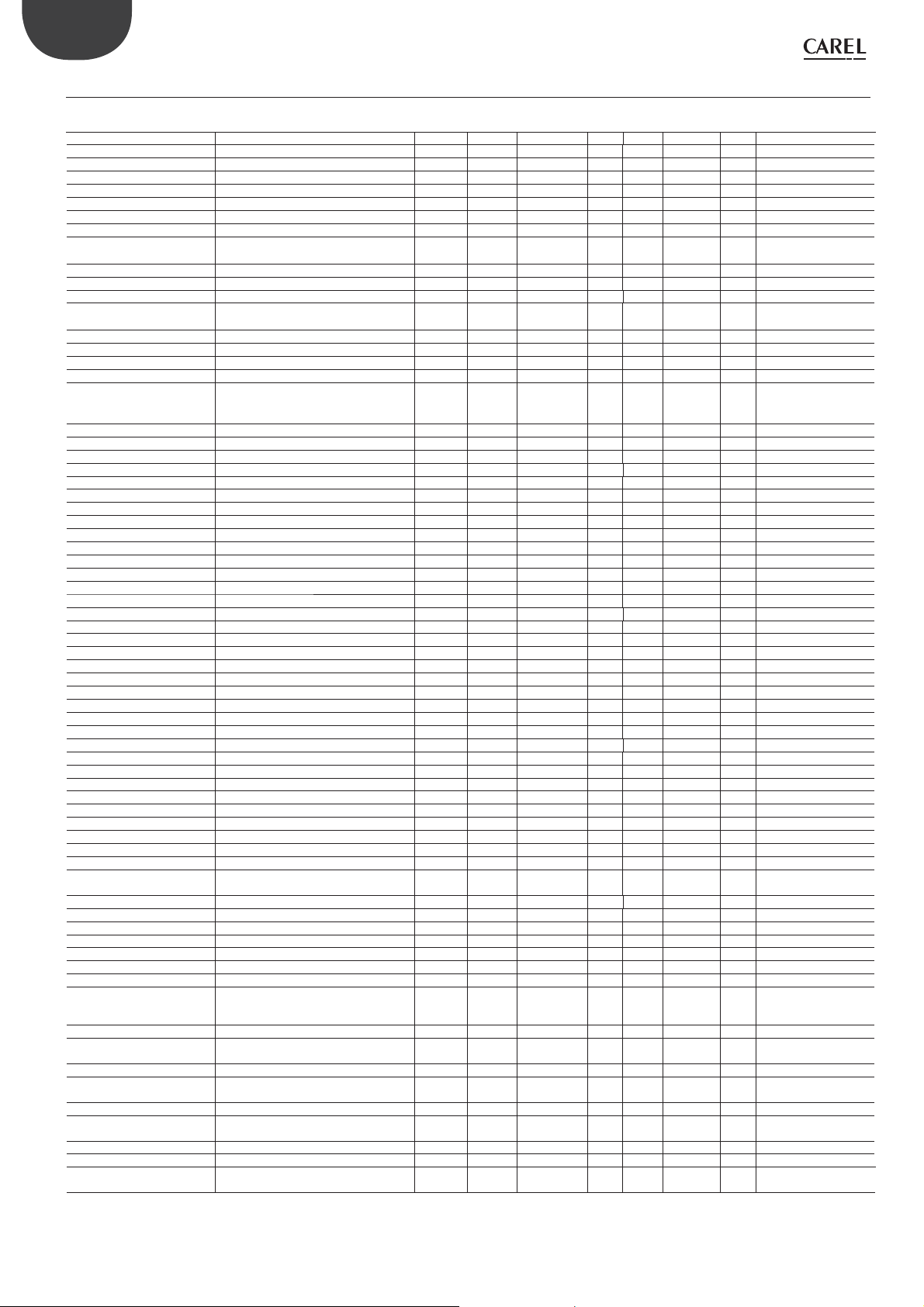
ENG
8.8 Variables accessible via serial connection
Parameter Description Def. Min Max Type Carel Modbus® R/W Notes
Reg_status Controller status 0 0 20 I 1 128 R
Machine_type_SPV Type of unit 0 0 32767 I 2 129 R
Hardware_code_SPV Hardware code 0 0 32767 I 3 130 R
EEV_Positions_steps Valve position 0 0 999 I 4 131 R
Protection_status Protection status 0 0 5 I 5 132 R
Sh_unit_power_percent Cooling capacity 0 0 100 I 6 133 R/W
Man_posit_steps Manual valve position 0 0 999 I 7 134 R/W par. U2
Start_func_test Input variable in functional test 0 0 30000 I 8 135 R/W
Func_test_2 Generic variable to use in the functional
test
Net_address LAN serial network address 99 1 99 I 10 137 R/W par. n1
EEV_steps_doubling Double valve steps 1 1 2 I 11 138 R/W par. U3
Gas_type Refrigerant 3 1 23 I 12 139 R/W Gas Type = refrigerant
Super_main_regulation Main control 1 0 9 I 13 140 R/W Mode = operating
Super_S1_probe_model Probe S1 3 1 14 I 14 141 R/W par. S1
Inhibit_mode_setting Enable mode parameter setting 0 0 1 I 15 142 R/W par. IA
Unity_measure Unit of measure 1 1 2 I 16 143 R/W par. Si
PID_Ti PID: integral time 150 0 999 I 17 144 R/W par. ti
Par_Digin1_Config Digital input configuration
1=Start/stop control
2=Control backup
Start_eev_opening_ratio Valve position at start-up 50 0 100 I 19 146 R/W par. U4
Net setting Baud rate 2 0 17 I 20 147 R/W par. n2
Reset Default(*) Reset factory parameters 0 -32768 32767 I 21 148 R/W
Ultracella signature Reserved 0 -32768 32767 I 22 149 R/W
Regulation type Type of control 1 1 9 I 23 150 R
Gas custom dew_a_h Dew point a high -288 -32768 32767 I 24 151 R/W
Gas custom dew_a_l Dew point a low -15818 -32768 32767 I 25 152 R/W
Gas custom dew_b_h Dew point b high -14829 -32768 32767 I 26 153 R/W
Gas custom dew_b_l Dew point b low 16804 -32768 32767 I 27 154 R/W
Gas custom dew_c_h Dew point c high -11664 -32768 32767 I 28 155 R/W
Gas custom dew_c_l Dew point c low 16416 -32768 32767 I 29 156 R/W
Gas custom dew_d_h Dew point d high -23322 -32768 32767 I 30 157 R/W
Gas custom dew_d_l Dew point d low -16959 -32768 32767 I 31 158 R/W
Gas custom dew_e_h Dew point e high -16378 -32768 32767 I 32 159 R/W
Gas custom dew_e_l Dew point e low 15910 -32768 32767 I 33 160 R/W
Gas custom dew_f_h Dew point f high -2927 -32768 32767 I 34 161 R/W
Gas custom dew_f_l Dew point f low -17239 -32768 32767 I 35 162 R/W
Net_alarm Network alarm 0 0 1 D 1 0 R al. E6
Emergency_closing_alarm No power supply 0 0 1 D 2 1 R al. E5
S1_alarm Probe S1 alarm 0 0 1 D 3 2 R al. A1
S2_alarm Probe S2 alarm 0 0 1 D 4 3 R al. A2
Low_sh_alarm Low_SH alarm 0 0 1 D 5 4 R al. E3
LOP_alarm LOP alarm 0 0 1 D 6 5 R al. E2
MOP_alarm MOP alarm 0 0 1 D 7 6 R al. E1
Low_suct_alarm Low suction temperature alarm 0 0 1 D 8 7 R al. E4
Eeprom_alarm EEPROM damaged 0 0 1 D 9 8 R al. EE
Digin1_status Digital input status 0 0 1 D 10 9 R
Manual_posit_enable Enable manual valve 0 0 1 D 11 10 R/W par. U1
Incomplete closing alarm Emergency closing not completed 0 0 1 D 12 11 R/W al. E8
Battery alarm Battery alarm 0 0 1 D 13 12 R
EVD_CAN_GO Enable EVD control 0 0 1 D 14 13 R/W
S1_Alarm_enable Enable probe S1 0 0 1 D 15 14 R/W
S2_Alarm_enable Enable probe S2 0 0 1 D 16 15 R/W
EEV_Position_percent Valve opening 0 0 100 A 1 0 R par. Po
SH_SH Superheat 0 -5
Sh_Suct_temp Suction temperature 0 -85(-121) 200(392) A 3 2 R par. tS
Sh_Evap_temp Evaporation temperature 0 -85(-121) 200(392) A 4 3 R
Sh_Evap_pres Evaporation pressure 0 -20(-290) 200(2900) A 5 4 R
S1_Value Probe S1 reading 0 -85(-290) 200(2900) A 6 5 R par. P1
S2_Value Probe S2 reading 0 -85(-121) 200(392) A 7 6 R par. P2
Positioning_mode_volt 0-10 V input 0 0 10 A 8 7 R
Firm_release Firmware version 0 0 800 A 9 8 R par. Fr
SH_Set Superheat set point 11 Low_
PID_Kp PID: proportional gain 15 0 800 A 11 10 R/W par. CP
Low_sh_threshold Low superheat: threshold 5 -5(-9) Set point
Low_sh_Ti Low superheat: integral time 15 0 800 A 13 12 R/W par. C2
Lop_threshold LOP: threshold -50(-58) -85(-121) MOP_th-
Lop_Ti LOP: integral time 0 0 800 A 15 14 R/W par. C4
MOP_Threshold MOP: threshold 50 LOP_th-
MOP_Ti MOP: integral time 20 0 800 A 17 16 R/W par. C6
Low_Suct_alarm_threshold Low suction temperature alarm threshold -50(-58) -85(-121) 200(392) A 18 17 R/W par. C8
Mop_Inhibition_threshold MOP: inhibition threshold 30 (86) -85
0 -32768 32767 I 9 136 R/W
1 1 2 I 18 145 R/W
(-9)
Sh_Threshold
reshold
(-121)
55
(99)
55(99) A 10 9 R/W Super heat = superheat
surrisc.
reshold
200
(392)
200
(392)
A2 1 R
A 12 11 R/W par. C1
A 14 13 R/W par. C3
A 16 15 R/W par. C5
A 19 18 R/W
mode
set point
“EVD mini” +0300036EN - rel. 1.2 - 23.04.2018
26
Page 27

Parameter Description Def. Min Max Type Carel Modbus® R/W Notes
S1_Alarm_threshold_
low
S1_Alarm_threshold_
high
TCTRL_REV_SET Hot gas bypass temperature set point 10 -85
PCTRL_REV_SET Hot gas bypass pressure set point 3 -20
SH_actual_set Reserved
SH_Set_smooth_line Superheat set point offset for smooth
S1_value_remote S1 probe reading from supervisor
(*) set to 1973 to reset the parameters to the default values
Pressure S1: MINIMUM alarm value -1 -85(-290) Par_S1_
Pressure S1: MAXIMUM alarm value 9.3 Par_
0
0
lines
0
S1_Ala
rm_threshold _
low
(-121)
(-290)
-40(-72)
-55(-99)
-20(-290)
Alarm_threshold _
high
200(2900) A 21 20 R/W
200
(392)
200
(2900)
180(324) A 24 23 R
55(99) A 25 24 R/W
200(2900) A 26 25 R/W
A 20 19 R/W
A 22 21 R/W par. _t
A 23 22 R/W par. _P
ENG
Tab. 8.c
8.9 Control states
The electronic valve controller can have six different control states,
each of which may correspond to a specific phase in the operation of
the refrigeration unit and a certain status of the driver-valve system. The
states are as follows:
• forced closing: initialisation of the valve position when switching the
instrument on;
• standby: no temperature control, unit OFF (at temp.);
• wait: opening of the valve before starting control, also called pre-
positioning, when powering the unit on;
• control: effective control of the electronic valve, unit ON;
• positioning: step-change in the valve position, corresponding to the
start of control when the cooling capacity of the controlled unit varies
(only EVD connected to a pCO);
• stop: of control with closing of the valve, corresponds to the end of
temperature control of the refrigeration unit, unit OFF (at temp.).
Forced closing
Forced closing is performed after the driver is powered on and corresponds
to the typical number of closing steps for CAREL E2V and E3V unipolar valves.
This is used to realign the valve to the physical position corresponding to
completely closed. The driver and the valve are then ready for control and
both aligned at 0 (zero). At power-on, first a forced closing is performed,
and then the standby phase starts. The valve is also closed in the event of
a mains power failure if the Ultracap module is connected. In this case, the
“Forced valve closing not completed” parameter is set to 1. On restarting, if
the valve forced closing procedure is not completed successfully:
1. the Master programmable controller (pCO) will check the value of
the parameter, and if equal to 1 will decide the best strategy to adopt,
based on the application;
2. on restarting the driver positions the valve as explained in the
paragraph “Pre-positioning/start control”. The parameter is set to 0
(zero) by the Master controller (e.g. pCO), or alternatively by pressing
the PRG/Set button on the keypad. Once the parameter has been
set to 1, the driver sets it back to 0 (zero) only if an emergency forced
closing procedure is completed successfully.
Note: lthe user can only select the resolution of the valve control
signal: 480 or 960 steps.
Par. Description Def. Min. Max. UoM
U3 Valve control steps
1 / 2 = 480/ 960 steps
Standby
Standby corresponds to a situation of rest in which no signals are received
to control the electronic valve: it is closed and manual positioning can be
activated. This status is normally set on the driver when the refrigeration
unit is shutdown manually (e.g. from the supervisor) or when reaching the
control set point. It can also occur when opening the digital input (which
involves closing the valve) or in the event of a probe alarm. In general, it can
be said that the electronic valve driver is in standby when the compressor
stops or the control solenoid valve closes.
12-
1
Pre-positioning/start control
If during standby a control request is received, before starting control the
valve is moved to a precise initial position. Internally, the pre-positioning
time is set at 6 s and represents the time that the valve is held in a fixed
position. By default the valve is opened 50 % when starting (from digital
input), so as to minimise the movement needed to reach the correct
position.
Par. Description Def. Min. Max. UoM
U4 Valve opening at start-up 50
This parameter should be set based on the ratio between the rated
cooling capacity of the evaporator and the valve (e.g. rated evaporator
cooling capacity: 3kW, rated valve cooling capacity: 10kW, valve opening
= 3/10 = 33%).
The driver calculates the valve opening based on the required capacity:
If required capacity is 100%:
Opening (%)= (Valve opening at start-up);
If required capacity is less than 100% (capacity control):
Opening (%)= (Valve opening at start-up) x (Current unit cooling
capacity), where the current unit cooling capacity is sent to the driver
via RS485 by the pCO controller. If the driver is stand-alone, this is always
equal to 100%.
Notes:
0 100 %
• this procedure is used to anticipate the movement and bring the valve
significantly closer to the operating position in the phases immediately
after the unit is powered on;
• if there are problems with liquid return after the refrigeration unit starts
or in units that frequently switch on-off, the valve opening at start-up
must be decreased. If there are problems with low pressure after the
refrigeration unit starts, the valve opening must be increased.
Wait
When the calculated position has been reached, regardless of the time taken
(this varies according to the type of valve and the objective position), there
is a constant 5 second delay before the actual control phase starts. This is to
create a reasonable interval between standby, in which the variables have no
meaning, as there is no flow of refrigerant, and the effective control phase.
Control
The control request can be received by the closing of the digital input
or via network (RS485). The solenoid or the compressor are activated
when the valve, following the pre-positioning procedure, has reached
the calculated position. The following figure represents the sequence of
events for starting control of the refrigeration unit.
27
“EVD mini” +0300036EN - rel. 1.2 - 23.04.2018
Page 28

ENG
ON
A
OFF
ON
S
OFF
ON
P
OFF
ON
R
OFF
T1 W
Fig. 8.o
Key:
A Control request T1 Pre-positioning time
P Pre-positioning W Wait (wait)
S Standby t Time
R Control
t
t
t
t
Positioning (change cooling capacity)
This control status is only valid for controllers connected to the pCO
via RS485. If there is a change in unit cooling capacity of at least 10%,
sent from the pCO via RS485, the valve is positioned proportionally. In
practice, this involves repositioning starting from the current position in
proportion to how much the cooling capacity of the unit has increased or
decreased in percentage terms. When the calculated position has been
reached, regardless of the time taken, there is a constant 5 second delay
before the actual control phase starts.
Note: if information is not available on the variation in unit cooling
capacity, this will always be considered as operating at 100% and therefore
the procedure will never be used. In this case, the PID control must be
more reactive (see the chapter on Control) so as to react promptly to
variations in load that are not communicated to the driver.
ON
A
OFF
t
ON
C
OFF
t
ON
NP
OFF
t
ON
R
OFF
t
T3 W
ON
A
OFF
ON
S
OFF
ON
ST
OFF
ON
R
OFF
T4
Fig. 8.q
Key:
Control request R Control
A
Standby T4 Stop position time
S
Stop t Time
ST
t
t
t
t
8.10 Special control states
As well as normal control status, the driver can have three special states
related to specific functions:
• manual positioning: this is used to interrupt control so as to move the
valve, setting the desired position;
• recover physical valve position: recover physical valve steps when fully
opened or closed;
• unblock valve: forced valve movement if the driver considers it to be
blocked.
Manual positioning
Manual positioning can be activated at any time during the standby or
control phase. Manual positioning, once enabled, is used to freely set the
position of the valve using the corresponding parameter.
Control is placed on hold, all the system and control alarms are enabled,
however neither control nor the protectors can be activated. Manual
positioning thus has priority over any driver state/protector.
Par. Description Def. Min. Max. UoM
U1 Enable manual valve positioning:
0/1=yes/no
U2 Manual valve position 0
Notes:
1. the manual positioning status is NOT saved when restarting after a
power failure.
2. in for any reason the valve needs to be kept stationary after a power
failure, proceed as follows:
• remove the valve stator;
• set the PID proportional gain =0. The valve will remain stopped at
the initial opening position, set by corresponding parameter
01-
0
0 999
step
Fig. 8.p
Key:
Control request R Control
A
Change in capacity T3 Repositioning time
C
Repositioning t Time
NP
Wait
W
Stop/end control
The stop procedure involves closing the valve from the current position
until reaching 0 steps, plus a further number of steps so as to guarantee
complete closing. Following the stop phase, the valve returns to standby.
“EVD mini” +0300036EN - rel. 1.2 - 23.04.2018
28
Page 29

Retrieve physical valve position
This procedure is necessary as the stepper motor intrinsically tends to
lose steps during movement. Given that the control phase may last
continuously for several hours, it is probable that from a certain time
on the estimated position sent by the valve driver does not correspond
exactly to the physical position of the movable element. This means that
when the driver reaches the estimated fully closed or fully open position,
the valve may physically not be in that position. The “Synchronisation”
procedure allows the driver to perform a certain number of steps in the
suitable direction to realign the valve.
Note: realignment is in intrinsic part of the forced closing procedure
and is activated whenever the driver is stopped/started and in the
standby phase.
Unblock valve
This procedure is only valid when the driver is performing superheat
control. Unblock valve is an automatic safety procedure that attempts
to unblock a valve that is supposedly blocked based on the control
variables (superheat, valve position). The unblock procedure may or may
not succeed depending on the extent of the mechanical problem with
the valve. If for 10 minutes the conditions are such as to assume the valve
is blocked, the procedure is run a maximum of 5 times. The symptoms of
a blocked valve do not necessarily mean a mechanical blockage. They
may also represent other situations:
• mechanical blockage of the solenoid valve upstream of the electronic
valve (if installed);
• electrical damage to the solenoid valve upstream of the electronic
valve;
• blockage of the filter upstream of the electronic valve (if installed);
• electrical problems with the electronic valve motor;
• electrical problems in the driver-valve connection cables;
• incorrect driver-valve electrical connection;
• incorrect driver-valve electrical connection;
• electronic problems with the valve control driver;
• secondary fluid evaporator fan/pump malfunction;
• insufficient refrigerant in the refrigerant circuit;
• refrigerant leaks;
• lack of subcooling in the condenser;
• electrical/mechanical problems with the compressor;
• processing residues or moisture in the refrigerant circuit.
ENG
Note: the valve unblock procedure is nonetheless performed in
each of these cases, given that it does not cause mechanical or control
problems. Therefore, also check these possible causes before replacing
the valve.
29
“EVD mini” +0300036EN - rel. 1.2 - 23.04.2018
Page 30
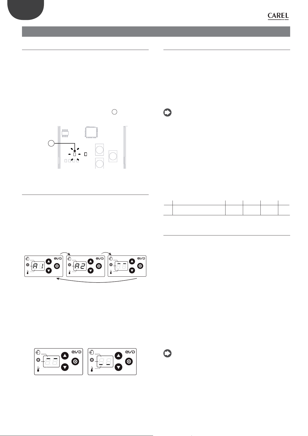
ENG
9. ALARMS
9.1 Types of alarms
There are two types of alarms:
• system: EEPROM, probe and communication;
• control: low superheat, LOP, MOP, low suction temperature.
The activation of the alarms depends on the setting of the threshold and
activation delay parameters. The EEPROM unit parameters and operating
parameters alarm always shuts down the controller and cannot be reset.
All the alarms are reset automatically, once the causes are no longer
present, except for the “Emergency closing not completed” alarm, which
requires manual reset.
1
Example 1: the board without display has the red
alarm is active. For EEPROM alarms, it stays on steady.
flashing when an
1
Fig. 9.a
9.2 Probe alarms
The probe alarms are part of the system alarms. When the value measured
by one of the probes is outside of the range of measurement, an alarm
is activated. The alarm limits correspond to the range of measurement.
In the event of a probe alarm, the driver closes the valve, regardless of
digital input status, until the error is no longer present.
Example: the display shows probe alarms A1 and A2 in sequence. The
superheat value has exceeded the maximum limit allowed, and this is
indicated by the two top segments.
GAS Type
Mode
Super Heat
GAS Type
Mode
Super Heat
Fig. 9.b
Minimum and maximum superheat limits
If a probe alarm occurs, it may be due to the superheat value exceeding
the allowed display range -5…55 K (-9 to 99°F). The display therefore
shows the probe alarm code (A1/A2) and:
1. if the superheat value is less than -5K, the display shows the two
bottom segments;
2. if the superheat value is higher than 55K, the display shows the two
top segments.
GAS Type
Mode
Super Heat
9.3 Control alarms
These are alarms that are only activated during control.
Protector alarms
The alarms corresponding to the LowSH, LOP and MOP protectors are only
activated during control when the corresponding activation threshold is
exceeded, and only when the delay time defined by the corresponding
parameter has elapsed. If a protector is not enabled (integral time= 0 s),
no alarm will be signalled. If before the expiry of the delay, the protector
control variable returns back inside the corresponding threshold, no
alarm will be signalled.
Note: this is a likely event, as during the delay, the protection
function will have an effect.
Low suction temperature alarm
The low suction temperature alarm is not linked to any protection function.
It features a threshold and a fixed delay (300 seconds), and is useful in the
event of probe or valve malfunctions to protect the compressor using
the relay to control the solenoid valve or to simply signal a possible risk.
In fact, incorrect measurement of the evaporation pressure or incorrect
configuration of the type of refrigerant may mean the superheat
calculated is much higher than the actual value, causing an incorrect and
excessive opening of the valve. A low suction temperature measurement
may in this case indicate probable flooding of the compressor, with
corresponding alarm signal. The alarm is reset automatically, with a fixed
differential of 3°C above the activation threshold.
Par. Description Def. Min. Max. UoM
C8 Low suction temperature
alarm threshold
-50
(-58)
-85
(-121)
200
(392)
°C(°F)
9.4 Valve emergency closing procedure
The following description only applies if EVD mini is connected to the
Ultracap module.
In the event of a power failure, EVD mini can provide emergency
closing of the valve, thus preventing any refrigerant from flowing to the
compressor.
In this situation, the driver generates two alarms: E8 and E5. If the
procedure concludes successfully (the valve closes completely), alarm E8
is cleared, however alarm E5 continues until the Ultracap module is able
to power on the driver.
• E8: failed emergency closing (incomplete closing alarm). Active
during the emergency closing stage and until the valve closes
completely, after which alarm E8 is cleared. If the closing procedure
is not completed (e.g. because the Ultracap module does not have
enough charge), when next restarting the controller, the user must
manually reset the alarm (pressing the PRG/SET button or setting the
corresponding parameter to zero via serial connection);
• E5: emergency closing (emergency force closing alarm). This depends
on a controller power failure and indicates that the emergency
procedure is in progress.
GAS Type
Mode
Super Heat
12
“EVD mini” +0300036EN - rel. 1.2 - 23.04.2018
Mode
Fig. 9.c
GAS Type
Super Heat
Notes:
• if the voltage measured falls below a certain threshold, the controller,
connected to the Ultracap module, can start the valve emergency
closing procedure;
• during the valve emergency closing procedure, the display is switched
off to save energy (therefore the alarms may not be shown on the
display, or only shown for a brief instant);
• if power returns during the closing procedure, alarms E8 and E5 are
reset and closing is completed in any case.
30
Page 31

9.5 Network alarm
The digital input configuration parameter can only be set to control
backup from the supervisor. If there is a communication error between
the pCO controller and driver, the digital input status determines whether
to continue control (input closed = the valve remains in the current
position) or stop (input open).
9.6 Alarm table
ENG
Alarm code on
the display
A1 flashes Probe S1 faulty or set alarm range
A2 flashes Probe S2 faulty or set alarm range
E1 flashes MOP protection activated automatic Protection action already
E2 flashes LOP protection activated automatic Protection action already
E3 flashes LowSH protection activated automatic Protection action already
E4 flashes Low suction temperature automatic No effect Check the threshold parameter.
E5 flashes Chiusura di emergenza: LowSH,
E6 flashes Network error automatic Control based on DI Check the wiring and that the pCO is
E7 flashes Ultracap module powered at low volta-
E8 flashes Emergency closing not completed Manual Valve closed Press PRG/Set or set the corresponding
EE on steady EEPROM operating and/or unit parame-
Red LED Cause of the alarm Reset Effects on control Checks / Solutions
exceeded
exceeded
LOP, MOP, bassa T/P di aspirazione,
mancanza di alimentazione
ge or low charge
ters damaged
automatic Valve closed Check the probe connections.
automatic Valve closed Check the probe connections.
in progress
in progress
in progress
automatic Valve closed Reset power supply
automatic No effect Check the wiring, the power supply
Replace the
driver/ Contact
service
Total shutdown Replace the driver/Contact service
Check parameter “MOP protection:
threshold”
Check parameter “LOP protection:
threshold”
Check parameter “LowSH protection:
threshold”
on and operating
and that the minimum recharge time
has elapsed
supervisor variable to 0
Tab. 9.d
31
“EVD mini” +0300036EN - rel. 1.2 - 23.04.2018
Page 32

ENG
10. TROUBLESHOOTING
The following table lists a series of possible malfunctions that may occur
when starting and operating the driver and the electronic valve. These
cover the most common problems and are provided with the aim of
offering an initial response for resolving the problem.
PROBLEM CAUSE SOLUTION
The superheat value measured is incorrect
Liquid returns to the compressor during control
Liquid returns to the compressor only after defrosting
(for multiplexed cabinets
only)
Liquid returns to the compressor only when starting
the controller (after being
OFF)
The superheat value swings
around the set point with an
amplitude greater than 4°C
In the start-up phase with
high evaporator temperatures, the evaporation
pressure is high
The probe does not measure correct values Check that the pressure and the temperature measured are correct and that the probe
The type of refrigerant set is incorrect Check and correct the type of refrigerant parameter.
The superheat set point is too low Increase the superheat set point. Initially set it to 11 K and check that there is no longer
Low superheat protection ineffective If the superheat remains low for too long with the valve that is slow to close, increase
Stator broken or connected incorrectly Disconnect the stator from the valve and the cable and measure the resistance of the
Valve stuck open Check if the superheating is always low (<2 °C) with the valve position permanently at
The “valve opening at start-up” parameter
is too high on many cabinets in which
the control set point is often reached (for
multiplexed cabinets only)
The superheat temperature measured
by the driver after defrosting and before
reaching operating conditions is very low
for a few minutes
The superheat temperature measured by
the driver does not reach low values, but
there is still return of liquid to the compressor rack
Many cabinets defrosting at the same time Stagger the start defrost times. If this is not possible, if the conditions in the previous
The valve is significantly oversized Replace the valve with a smaller equivalent.
The “valve opening at start-up” parameter is
set too high
The condensing pressure swings Check the controller condenser settings, giving the parameters “blander” values (e.g.
The superheat swings even with the valve
set in manual control (in the position corresponding to the average of the working
values)
The superheat does NOT swing with the
valve set in manual control (in the position
corresponding to the average of the working values)
The superheat set point is too low Increase the superheat set point and check that the swings are reduced or disappear.
MOP protection disabled or ineffective Activate the MOP protection by setting the threshold to the required saturated eva-
Refrigerant charge excessive for the system
or extreme transitory conditions at start-up
(for cabinets only).
position is correct.
correct probe electrical connections.
return of liquid. Then gradually reduce the set point, always making sure there is no
return of liquid.
the low superheat threshold and/or decrease the low superheat integration time.
Initially set the threshold 3 °C below the superheat set point, with an integration time
of 3-4 seconds. Then gradually lower the low superheat threshold and increase the low
superheat integration time, checking that there is no return of liquid in any operating
conditions.
windings using an ordinary tester.
The resistance of both should be around 40 ohms. Otherwise replace the stator.
0 steps. If so, set the valve to manual control and close it completely. If the superheat is
always low, check the electrical connections and/or replace the valve.
Decrease the value of the “Valve opening at start-up” parameter on all the utilities,
making sure that there are no repercussions on the control temperature.
Check that the LowSH threshold is greater than the superheat value measured and that
the corresponding protection is activated (integration time >0 s). If necessary, decrease
the value of the integration time.
Set more reactive parameters to bring forward the closing of the valve: increase the
proportional factor to 30, increase the integration time to 250 s.
two points are not present, increase the superheat set point and the LowSH thresholds
by at least 2 °C on the cabinets involved.
Check the calculation in reference to the ratio between the rated cooling capacity of
the evaporator and the capacity of the valve; if necessary, lower the value.
increase the proportional band or increase the integration time). Note: the required
stability involves a variation within +/- 0.5 bars. If this is not effective or the settings
cannot be changed, adopt electronic valve control parameters for perturbed systems
Check for the causes of the swings (e.g. low refrigerant charge) and resolve where
possible.
As a first approach , decrease (by 30 to 50 %) the proportional factor. Subsequently try
increasing the integration time by the same percentage. In any case, adopt parameter
settings recommended for stable systems.
Initially set 13 °C, then gradually reduce the set point, making sure the system does not
start swinging again and that the unit temperature reaches the control set point.
poration temperature (high evaporation temperature limit for the compressors) and
setting the MOP integration time to a value above 0 (recommended 4 seconds). To
make the protection more reactive, decrease the MOP integration time.
Apply a “soft start” technique, activating the utilities one at a time or in small groups. If
this is not possible, decrease the values of the MOP thresholds on all the utilities.
Make sure the correct pressure probe has been set. Check the
“EVD mini” +0300036EN - rel. 1.2 - 23.04.2018
32
Page 33

PROBLEM CAUSE SOLUTION
In the start-up phase the
low pressure protection
is activated (only for selfcontained units)
The unit switches off due to
low pressure during control
(only for self-contained
units)
The “Valve opening at start-up” parameter
is set too low
The driver in RS485 network does not start
control and the valve remains closed
The driver in stand-alone configuration
does not start control and the valve
remains closed
LOP protection disabled Set a LOP integration time greater than 0 s.
LOP protection ineffective Make sure that the LOP protection threshold is at the required saturated evaporation
Solenoid blocked Check that the solenoid opens correctly, check the electrical connections.
Insufficient refrigerant Check that there are no bubbles in the sight glass upstream of the expansion valve.
The valve is connected incorrectly (rotates
in reverse) and is open
Stator broken or connected incorrectly Disconnect the stator from the valve and the cable and measure the resistance of the
Valve stuck closed Use manual control after start-up to completely open the valve. If the superheat
LOP protection disabled Set a LOP integration time greater than 0 s.
LOP protection ineffective Make sure that the LOP protection threshold is at the required saturated evaporation
Solenoid blocked Check that the solenoid opens correctly, check the electrical connections and the
Insufficient refrigerant Check that there are no bubbles of air in the liquid indicator upstream of the expansion
The valve is significantly undersized Replace the valve with a larger equivalent.
Stator broken or connected incorrectly Disconnect the stator from the valve and the cable and measure the resistance of the
Valve stuck closed Use manual control after start-up to completely open the valve. If the superheat
Check the calculation in reference to the ratio between the rated cooling capacity of
the evaporator and the capacity of the valve; if necessary lower the value.
Check the serial connection. Check that the pCO application connected to the driver
(where featured) correctly manages the driver start signal. Check that the driver is NOT
in stand-alone mode.
Check the connection of the digital input. Check that when the control signal is sent
that the input is closed correctly. Check that the driver is in stand-alone mode.
temperature (between the rated evaporation temperature of the unit and the corresponding temperature at the calibration of the low pressure switch) and decrease the
value of the LOP integration time.
Check that the subcooling is suitable (greater than 5 °C); otherwise charge the circuit.
Check the movement of the valve by placing it in manual control and closing or opening it completely. One complete opening must bring a decrease in the superheat and
vice-versa. If the movement is reversed, check the electrical connections.
windings using an ordinary tester.
The resistance of both should be around 40 ohms. Otherwise replace the stator.
remains high, check the electrical connections and/or replace the valve.
temperature (between the rated evaporation temperature of the unit and the corresponding temperature at the calibration of the low pressure switch) and decrease the
value of the LOP integration time.
operation of the control relay.
valve. Check that the subcooling is suitable (greater than 5 °C); otherwise charge the
circuit.
windings using an ordinary tester.
The resistance of both should be around 40 ohms. Otherwise replace the stator.
remains high, replace the valve body.
ENG
The cabinet does not reach
the set temperature, despite
the value being opened to
the maximum (for multiplexed cabinets only)
The cabinet does not reach
the set temperature, and
the position of the valve is
always 0 (for multiplexed
cabinets only)
Solenoid blocked Check that the solenoid opens correctly, check the electrical connections and the
Insufficient refrigerant Check that there are no bubbles of air in the liquid indicator upstream of the expansion
The valve is significantly undersized Replace the valve with a larger equivalent.
Stator broken or connected incorrectly Disconnect the stator from the valve and the cable and measure the resistance of the
Valve stuck closed Use manual control after start-up to completely open the valve. If the superheat
The driver in RS485 network does not start
control and the valve remains closed
The driver in stand-alone configuration
does not start control and the valve
remains closed
operation of the relay.
valve. Check that the subcooling is suitable (greater than 5 °C); otherwise charge the
circuit.
windings using an ordinary tester.
The resistance of both should be around 40 Ω. Otherwise replace the stator.
remains high, replace the valve body.
Check the network connections. Check that the pCO application connected to the
driver (where featured) correctly manages the driver start signal. Check that the driver is
NOT in stand-alone mode.
Check the connection of the digital input. Check that when the control signal is sent
that the input is closed correctly. Check that the driver is in stand-alone mode.
33
“EVD mini” +0300036EN - rel. 1.2 - 23.04.2018
Page 34

ENG
11. TECHNICAL SPECIFICATIONS
EVD mini (24 V) EVD mini (230 V)
Power supply
1. 24 Vac (+10/-15%) 50/60 Hz.
• Use a class II isolating transformer (min 20VA, max 50VA)
• Length of connection between transformer and EVDmini
Lmax=1 m
2. 24 Vdc (+10/-15%)
• Use an external 24 Vdc power supply, min 15 W
Max power consumption (W) 13 15
Emergency power supply 13 Vdc +/-10% (If the optional Ultracap module for EVD mini is installed)
Driver Unipolar valve
Connections:
Motor connection 6-wire cable type AWG 18/22, Lmax=1m (see NOTE)
Digital inputs connection Digital input to be activated from voltage-free contact or
Probes Lmax=10 m for residential/industrial, 2 m for domestic environments
Power to active probes (V REF) +5Vdc+/-2%
RS485 serial connection Modbus, Lmax=500 m, shielded cable, earth both ends of the cable shield
Assembly on DIN rail or with screws on DIN rail
Connectors wire size 0,35...2,5 mm
Dimensions Base x height x depth = 88 x 90 x 33 mm Base x height x depth = 70,4 x 114 x 38 mm
Operating conditions -25T60°C; <90% U.R. non-condensing
Storage conditions -35T60°C, <90% U.R. non-condensing
Index protection IP00
Environmental pollution 2
Resistance to heat and fire Category D
Overvoltage category Category II
Insulation class III II
Class and software structure A
Conformity
Electrical safety EN 60730-1, UL 60730-1, UL 60730-2-9
Electromagnetic compatibility EN 61000-6-1, EN 61000-6-2, EN 61000-6-3, EN 61000-6-4
transistor to GND.
Closing current: 5mA.
Maximum contact resistance: <50Ω
Lmax=10 m for residential/industrial, 2 m for domestic environments
S1
Low temperature NTC:
Ratiometric pressure probe (0…5V)
S2
Low temperature NTC:
Input 0…10V
(max 12V)
10 kΩ a 25°C, -50T90°C
Measurement error: 1°C in the range -50T50°C; 3°C in the range +50T90°C
Resolution 0,1 % fs
Measurement error: 2% fs maximum; 1% typical
10kΩ a 25°C, -50T90°C
Measurement error: 1°C in the range -50T50°C; 3°C in the range +50T90°C
Resolution 0,1 % fs
Measurement error: 9% fs maximum; 8% typical
EN61000-3-2, EN55014-1, EN61000-3-3
115…230 Vac (+10/-15%) 50/60 Hz
• Length of power supply cable: Lmax=1 m.
Digital input 230 Vac optoisolated
Closing current: 10 mA
2
(12...22 AWG)
Note: if using in domestic and/or residential environments
(EN55014-1/EN61000-6-3) with the controller not installed inside a metallic panel, fit the ferrite (P/N 0907879AXX
):
• for EVD mini 24 V: applied on the valve stator cable if using in domestic/
residential environments with valve cable > 0.5 m;
• for EVD mini 115/ 230 V: applied on the valve stator cable if using in
domestic/residential environments with valve cable > 0-4 m.
“EVD mini” +0300036EN - rel. 1.2 - 23.04.2018
34
Page 35

Page 36

CAREL I NDUSTRIES HeadQuarters
Via dell’Industria, 11 - 35020 Brugine - Padova (Italy)
Tel. (+39) 049.9716611 - Fax (+39) 049.9716600
e-mail: carel@carel.com - www.carel.com
Agenzia / Agency:
“EVD mini” +0300036EN - rel. 1.2 - 23.04.2018
 Loading...