


easy / easy compact / easy split
electronic digital thermostats with defrost control
User manual
READ CAREFULLY IN THE TEXT!
Integrated Control Solutions & Energy Savings
NO POWER
& SIGNAL
CABLES
TOGETHER


ENG
WARNINGS
CAREL bases the development of its products on decades of experience
in HVAC, on the continuous investments in technological innovations
to products, procedures and strict quality processes with in-circuit and
functional testing on 100% of its products, and on the most innovative
production technology available on the market. CAREL and its subsidiaries
nonetheless cannot guarantee that all the aspects of the product and the
software included with the product respond to the requirements of the nal
application, despite the product being developed according to start-of-theart techniques. The customer (manufacturer, developer or installer of the nal
equipment) accepts all liability and risk relating to the conguration of the
product in order to reach the expected results in relation to the specic nal
installation and/or equipment. CAREL may, based on specic agreements, acts
as a consultant for the positive commissioning of the nal unit/application,
however in no case does it accept liability for the correct operation of the nal
equipment/system.
The CAREL product is a state-of-the-art device, whose operation is specied
in the technical documentation supplied with the product or can be
downloaded, even prior to purchase, from the website www.carel.com.
Each CAREL product, in relation to its advanced level of technology, requires
setup/conguration/programming/commissioning to be able to operate in
the best possible way for the specic application. The failure to complete such
operations, which are required/indicated in the user manual, may cause the
nal product to malfunction; CAREL accepts no liability in such cases.
Only qualied personnel may install or carry out technical service on the
product.
The customer must only use the product in the manner described in the
documentation relating to the product.
In addition to observing any further warnings described in this manual, the
following warnings must be heeded for all CAREL products
• prevent the electronic circuits from getting wet. Rain, humidity and all
types of liquids or condensate contain corrosive minerals that may damage
the electronic circuits. In any case, the product should be used or stored
in environments that comply with the temperature and humidity limits
specied in the manual.
• do not install the device in particularly hot environments. Too high
temperatures may reduce the life of electronic devices, damage them and
deform or melt the plastic parts. In any case, the product should be used
or stored in environments that comply with the temperature and humidity
limits specied in the manual.
• do not attempt to open the device in any way other than described in the
manual.
• do not drop, hit or shake the device, as the internal circuits and mechanisms
may be irreparably damaged.
• do not use corrosive chemicals, solvents or aggressive detergents to clean
the device.
• do not use the product for applications other than those specied in the
technical manual.
WARNINGS
NO POWER
& SIGNAL
CABLES
READ CAREFULLY IN THE TEXT!
Separate as much as possible the probe and digital input signal cables from
the cables carrying inductive loads and power cables to avoid possible
electromagnetic disturbance.
Never run power cables (including the electrical panel wiring) and signal
cables in the same conduits.
TOGETHER
DISPOSAL: INFORMATION FOR USERS
Fig. 1 Fig.2
PLEASE READ AND KEEP
With reference to European Union directive 2012/19/EU issued on 4 July
2012 and related national legislation, please note that:
1. Waste Electrical and Electronic Equipment (WEEE) cannot be disposed
of as municipal waste but must be collected separately so as to allow
subsequent recycling, treatment or disposal, as required by law;
2. users are required to take Electrical and Electronic Equipment (EEE)
at end-of-life, complete with all essential components, to the WEEE
collection centres identied by local authorities. The directive also
provides for the possibility to return the equipment to the distributor
or retailer at end-of-life if purchasing equivalent new equipment, on
a one-to-one basis, or one-to-zero for equipment less than 25 cm on
their longest side;
3. this equipment may contain hazardous substances: improper use or
incorrect disposal of such may have negative eects on human health
and on the environment;
4. the symbol (crossed-out wheeled bin – Fig.1) even if, shown on the
product or on the packaging, indicates that the equipment must be
disposed of separately at end-of-life;
5. if at end-of-life the EEE contains a battery (Fig. 2), this must be
removed following the instructions provided in the user manual
before disposing of the equipment. Used batteries must be taken to
appropriate waste collection centres as required by local regulations;
6. in the event of illegal disposal of electrical and electronic waste, the
penalties are specied by local waste disposal legislation.
All of the above suggestions likewise apply to the controllers, serial boards,
programming keys or any other accessory in the CAREL product portfolio.
CAREL adopts a policy of continual development. Consequently, CAREL
reserves the right to make changes and improvements to any product
described in this document without prior warning.
The technical specications shown in the manual may be changed without
prior warning.
The liability of CAREL in relation to its products is specied in the CAREL general
contract conditions, available on the website www.carel.com and/or by
specic agreements with customers; specically, to the extent where allowed
by applicable legislation, in no case will CAREL, its employees or subsidiaries
be liable for any lost earnings or sales, losses of data and information, costs of
replacement goods or services, damage to things or people, downtime or any
direct, indirect, incidental, actual, punitive, exemplary, special or consequential
damage of any kind whatsoever, whether contractual, extra-contractual or
due to negligence, or any other liabilities deriving from the installation, use or
impossibility to use the product, even if CAREL or its subsidiaries are warned
of the possibility of such damage.
3
easy/easy compact/easy split +030220791 - rel. 3.4 - 28.04.2021


Content
1. INTRODUCTION 7
1.1 Main characteristics ............................................................................................7
1.2 Models .......................................................................................................................7
1.3 Main dierences between easy, easy compact and easy split .........8
1.4 NTC and PTC probes .........................................................................................9
1.5 Accessories ..............................................................................................................9
1.6 Denitions ...............................................................................................................9
2. ASSEMBLY AND INSTALLATION 10
2.1 Assembly ...............................................................................................................10
2.2 Electrical connections ....................................................................................11
2.3 Wiring diagram for multiple units ........................................................13
3. USER INTERFACE AND START UP 14
3.1 easy ............................................................................................................................14
3.2 easy compact ......................................................................................................14
3.3 easy split .................................................................................................................14
3.4 Preliminary congurations ..........................................................................15
3.5 Functions available from the keypad....................................................15
ENG
4. FUNCTIONS AND PARAMETERS 16
4.1 Temperature probe settings ....................................................................... 16
4.2 Temperature display ....................................................................................... 16
4.3 Temperature control ...................................................................................... 17
4.4 Duty Setting ........................................................................................................17
4.5 Continuous cycle ...........................................................................................17
4.6 Compressor protection .................................................................................18
4.7 Defrost ....................................................................................................................18
4.8 Alarm parameters ............................................................................................20
4.9 Door open/closed management ...........................................................23
4.10 Evaporator fan management parameters .....................................24
4.11 Clock and time band parameters .........................................................25
4.12 Rapid parameter set selection (EZY) .................................................26
4.13 Other settings ..............................................................................................26
5. TABLES OF ALARMS AND PARAMETERS 28
5.1 Table of alarms and signals ........................................................................ 28
5.2 Description of the main signals and alarms .....................................29
5.3 Data error ...............................................................................................................29
5.4 Modifying the parameters..........................................................................29
5.5 Setting the default parameters ...............................................................30
5.6 Table of easy parameters ............................................................................. 30
5.7 Table of easy compact parameters .......................................................31
5.8 Table of easy split parameters .................................................................. 32
5.9 Table of EZY parameter sets ...................................................................... 33
5.10 Troubleshooting.............................................................................................35
6. TECHNICAL SPECIFICATIONS 36
6.1 Easy technical specications .....................................................................36
6.2 easy compact technical specications ...............................................36
6.3 easy split technical specications ..........................................................37
6.4 Electromagnetic compatibility ................................................................38
6.5 Flammable refrigerant gases ....................................................................38
5
easy/easy compact/easy split +030220791 - rel. 3.4 - 28.04.2021


1. INTRODUCTION
ENG
easy, easy compact and easy split are electronic microprocessor
controllers with LED display, developed for the management of
refrigerating units, display cabinets and showcases. They exploit the
experience and the success of the previous PJ32 range, with the objective
of oering a product that is simpler and more economical. The structure
of the parameters has been enhanced with new functions for more
dynamic and eective management of the temperature control and
defrost.
easy compact the smallest, most economical easy model, with one relay
only, and a simplied display.
easy split model with separate terminal and power board.
1.1 Main characteristics
The following table lists the main features of the easy, easy compact and
easy split controllers.
Features Models
Ergonomic polycarbonate keypad with three buttons
Keypad protection to prevent tampering
Access to the conguration parameters by password
Digit display -199…999 -99...99 -199…999
Decimal point
Display in °C or °F
LED display
Defrost (*) - by stopping the compressor
- heater
- hot gas
- heater with temperature control
Duty setting function
Continuous cycle function
Relay outputs (*)
Up to two analogue inputs for NTC or PTC probes (*)
Up to two analogue inputs for NTC/NTC-HT probes - Multifunction analogue or digital input (*)
In the models with at least 2 probes: display second/third probe (*)
Input for CAREL IROPZKEY** programming key (*)
Input for external CAREL IROPZ485 connector (RS485 network) (*)
Buzzer (audible alarm signals) (*)
Fixed or removable terminals
Fastening from rear or front
Easy Set (rapid instrument conguration selection)
(*) Check that this is available on the model in question.
easy easy compact easy split
P P P
P P P
P P P
P P P
P P P
P
P
P
P
P P P
P P P
P P
P
P P P
P P P
P P P
P
P P
P P P
P P P
P
-
-
-
-
-
P
P
P
P
-
P
P
P
-
Table 1.a
Important: each of the features should be checked for the model
in question.
1.2 Models
The easy and easy compact controllers dier as regards operation, and
the number inputs and outputs. easy split models feature a separate
terminal and power board. PQEZ* controllers are specically designed for
use in applications with ammable refrigerants.
easy models:
P(J,Q)EZS (0, 1, 6, 7)*; P(J,Q)EZ(X, Y)*; P(J,Q)EZC* controllers and P(J,Q)
EZM(0, 1, 6, 7)* thermometer only.
easy compact models:
P(J,Q)EZS(N, P)* controller and PJEZM(N,P)* thermometer only.
easy split models:
PJEZ*8**** controllers with one relay used for the light output.
Models and features
S models P(J,Q)EZS*
The ideal solution for the management of static refrigeration units (that is,
without fan on the evaporator), operating at normal temperature (above 0
°C). This model, in fact, performs the functions of thermometer, displaying
the temperature of the unit, and electronic thermostat, activating the
compressor (or the solenoid valve in the case of multiplexed units) so as
to maintain the required temperature. In addition, it features compressor
protection algorithms and automatic defrost function by shutting down
the compressor.
X and Y models P(J,Q)EZX*, P(J,Q)EZY*
These are designed for the management of static units operating at
low temperature (that is, below 0ºC), which require active defrost using
electric heaters or the injection of hot gas. The P(J,Q)EZ(Y,X)*, in fact,
as well as working as a thermometer and a thermostat (like the P(J,Q)
EZS), also manages the defrost actuator. The frequency and duration
of the defrost can be set. The end defrost can occur according to the
temperature reached (connecting a probe to the evaporator) or by time.
In addition these models feature two probe inputs, for the control probe
(room), the defrost probe, and a digital input (this can also be congured
as a probe). There are two outputs, for controlling the actuator (compressor
) and the defrost . Models P(J,Q)EZY and P(J,Q)EZX dier in that:
• P(J,Q)EZY has relays that are electrically connected together;
• P(J,Q)EZX has independent relays.
C models P(J,Q)EZC*
The most complete solution for low temperature ventilated units, with
three relays for complete control of the compressor, fan and defrost
functions. The three relays are included in the very compact case in the
versions with 230 V or 115 V power transformer, without compromising
the performance or reliability of the product.
M models P(J,Q)EZM*
Solution for simply measuring the temperature.
7
easy/easy compact/easy split +030220791 - rel. 3.4 - 28.04.2021
ENG
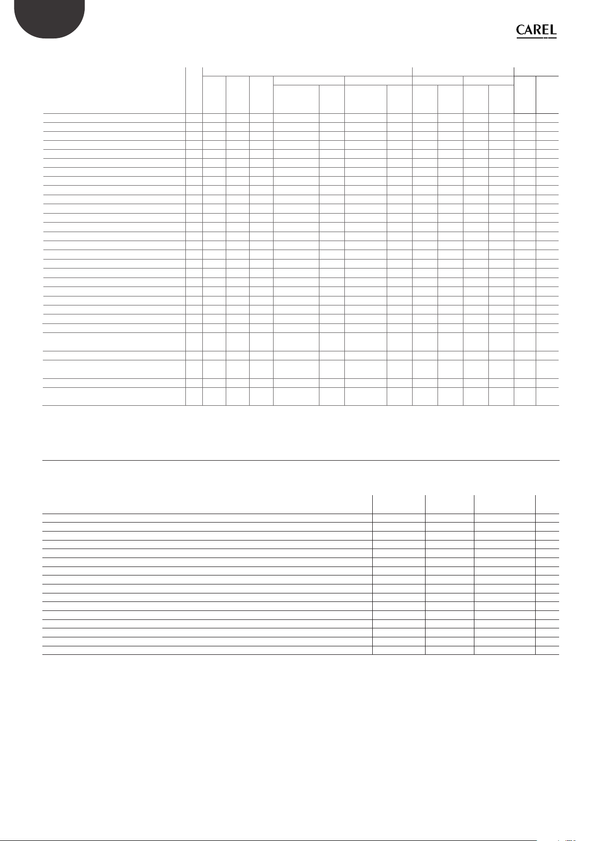
Summary table of the functions associated with the models
function see
mod.Cmod.Xmod.
par.
Y
temperature display 4.2
temperature measurement in °C/°F 4.2
parameter access using password 5.4
set point modication 3.5
night-time set point management 4.3
enable/disable direct probe 2 alarm 4.2 - - - - temperature probe calibration 4.1
temperature control in DIRECT mode 4.3
temperature control in REVERSE mode 4.3
compressor protectors 4.6
duty setting 4.4
continuous cycle 4.5
defrost 4.7
high/low temperature alarm 4.8
dirty condenser alarm 4.8
evaporator fan management 4.10
ON/OFF 3.5
AUX output conguration 4.13
enable/disable keypad 4.13
enable/disable buzzer 4.13
modied parameter detection 4.13
rapid parameter set selection 4.12
clock and time band management 4.11
door switch with light management 4.8 - - - - - - - - - - disable high temperature alarm when
starting
second compressor output in parallel 4.13 - - - - - - - - - - second comp. output with two step control
with or without rotation
fan management with comp. o 4.10 - - - - - - - - - - - night-time operation with light
management
* available but cannot be set from the keypad nor the programming key.
P P P P P P P P P P P P P
P P P P P P
P P P P P P
P P P P P P
P P P P
P P P P P P
P P P P P
P P P P P
P P P P P
P P P P P
P P P P P
P P P P P
P P P P P P
P P P P
- - - -
P
P P P P P P
P P P P P P
P P P P P P
P P P P P P
P P P P P P
P P P P P
P P P
5.1 - - - - - - - - - - -
4.13 - - - - - - - - - - -
4.11 - - - - - - - - - - -
easy easy compact easy split
mod.S mod.M mod.S mod.M mod. Smod.
2 probes +
multifun.
input
1
probe
-
-
2 probes +
multifun.
input
P
P
- -
- -
- -
- -
- -
- -
P
1
probe2prbs1probe2prbs1probe
*
P P P
*
P P P
*
P P P
- - - - -
- - -
*
P P P
P P
P P
P P
P P
P P
P P
P P P
*
P
-
P
- -
- -
- -
- -
- -
- -
P
-
- - - - - -
P P P
*
P P P
*
P P P
*
* - - - -
P P P
*
- -
- -
- - - - - -
P P
- -
*
P P
*
P P
*
P P
P P
- - -
*
P P
P P
P P
P P
P P
P P
P P
P P
*
P P
-
-
P P
*
P P
*
P P
*
P P
P P
*
P P
P P
P P
P P
P P
P P
P P
Table 1.b
C
P
P
1.3 Main differences between easy, easy compact and easy split
Unlike the easy and easy compact models, the easy split models feature a separate terminal and power board. There are also other dierences, such as the
auxiliary multifunction relay for managing the light output or a second compressor, and new software functions. The table below highlights the dierences
and indicates the page showing the related explanation.
topic
type of probes connectable (selectable by parameter, easy split only) NTC, PTC NTC, NTC-HT /P 9
dedicated relay for the light output NO YES H1=4 29
light on/o from the keypad defrost only YES H1=4 16
probe display rate function NO YES /3 17
curtain switch (night-time operation) with light management NO YES A4=4 24
light not managed/ managed with door switch and evaporator fan o NO YES A4=7, 10 25
light not managed/ managed with door switch and evaporator fan and compressor o NO YES A4=8, 11 25
door open/closed management NO YES Ado 25
second compressor output in parallel with dedicated relay NO YES H1=5 29
second compressor output with two step control with or without rotation NO YES H1=7/6 29
second compressor delay NO YES c11 19
fan management with compressor o NO YES F2=2, F4, F5 27
night-time operation with light management NO YES A4=4, H1=4 24
year, month, day of month setting NO YES YEr, MOn, dMO 28
disable high temperature alarm when starting NO YES - 31
maintenance request signal (SrC) NO YES HMP, HMd, HMr 30
easy, easy
compact
easy split
easy split
parameter
page
Table 1.c
easy/easy compact/easy split +030220791 - rel. 3.4 - 28.04.2021
8

1.4 NTC and PTC probes
All easy and easy compact models use PTC and NTC probes conforming
to the CAREL standard, with resistance values of 985Ω at 25°C for the
PTC, and 10 kΩ for the NTC. The type of probe installable depends on
the model (order code). The easy split models, on the other hand, only
use NTC and high temperature NTC probes (50 KΩ at 25°C), selected by
parameter. Below are some codes of the more common CAREL.
code description operating
NTC***HP00 NTC probe, 6x15 mm
bulb, plastic
NTC***HT00 High temp. NTC probe,
5x20 bulb mm, polyester
NTC***WP00 NTC probe , 6x40 mm
bulb, metal
PTC***W000 PTC probe, 6x40 mm
bulb, metal, 1.5 m long
range
-50T50°C IP67
0T120 °C
(max 150 °C for
3000 h)
-50T100°C IP67
-50T100°C IP67
index of
protection
IP55
Table 1.d
1.5 Accessories
• CAREL IROPZKEY* programming key (for duplicating the parameters);
• CAREL IROPZ485S0 RS485 converter (for the RS485 supervisory
network).
• CAREL USB/RS485 converter CVSTDUMOR0 to interface a RS485
network to a personal computer via the USB port;
• VPM, program downloadable from http://ksa.carel.com. This tool,
running on a computer, can be used to commission the controller,
program the parameters and update the rmware;
• COM TOOL, program downloadable from http://ksa.carel.com. This tool
can be used to program the controller from any PC, save the dierent
congurations in les that can be recalled during nal programming,
create custom sets of parameters for rapid programming and congure
the dierent users with password protected access proles. Connection
to the PC requires the USB/RS485 converter code CVSTDUMOR0;
• connection cable between terminal and power board (easy split only).
Available in dierent lengths (PEOPZC1500=1.5 m, PEOPZC3000=3.0
m, PEOPZC5000=5.0 m).
ENG
1.6 Definitions
Continuous cycle: function that runs the compressor for the set time.
Defrost: function that controls the defrost of the evaporator.
Duty setting: safety function that in the event of control probe faults
starts the compressor at set time intervals.
easy: trademark of the P(J,Q)EZ(S, X, Y, C, M)* thermostats.
easy compact: more compact and economical version of the easy.
Available in models PJEZ(S, M)*.
easy split: version with separate terminal and power board. Versions
available with (PJEZ*8R***) or without (PJEZ*8I***) RTC, and the power
board can be supplied with (PJEZ*8**5*) or without (PJEZ*8**4*) plastic
case.
9
easy/easy compact/easy split +030220791 - rel. 3.4 - 28.04.2021

ENG
1
2
PUSH
1
2
3
1
2
PUSH
1
2
PUSH
2. ASSEMBLY AND INSTALLATION
2.1 Assembly
Warnings:
Avoid installing the boards in environments with the following
characteristics:
• relative humidity greater than 90% or where there is condensation;
• strong vibrations or knocks;
• exposure to continuous water sprays;
• exposure to aggressive and polluting atmospheres(e.g.: sulphur and
ammonia fumes, saline mist, smoke) so as to avoid corrosion and/or
oxidation;
• strong magnetic and/or radio frequency interference (there avoid
installing the units near transmitting antennae);
• near transmitting antennae and to the elements in general;
• large and rapid uctuations in the ambient temperature;
• environments where explosives or mixes of ammable gases are
present;
• exposure to dust (formation of corrosive patina with possible oxidation
and reduction of insulation.
To install easy, easy compact and easy split: make an opening in the panel
based on the drilling template, 71x29 mm.
Panel installation using 2 rear brackets (Figs. 2.a and 2.b)
• insert the instrument in the opening (phase 1);
• secure the instrument by sliding the brackets in the guides on the
instrument until compressing them against the panel (phase 2);
easy
Fig. 2.a
2
PUSH
1
easy compact, easy split
• repeat the same operation for the top screw (phase 2);
• apply the front frame (phase 3).
(*)
max 2,5
Fig. 2.c
(*) do not over-tighten the screws.
3 mm
Dismantling using the screws from the front
• unclip the front frame;
• unscrew the bottom screw, at the moment the front panel detaches
from the panel keep pressure on the screw and unscrew a further 90°
to make the catch go back into its slot;
• repeat for the top screw;
• remove the instrument from panel, keeping it horizontal
easy split: power board dimensions and assembly
Assembly is performed using plastic spacers or plastic turrets. The power
board is supplied upon tted in a standard case for panel mounting,
dimensions 190x140x70.
117
103.5
5
4
Ø
L
36
8.5
5
Fig. 2.b
2
PUSH
98
88
RL1
RL4
5
RL3
RL2
L
N
N
7
1
Fig. 2.d
Removing from the panel with brackets
• release the instrument by pressing both brackets where marked “push”
and sliding it back on the guides.
Warnings:
• the connection cables must guarantee insulation at least up to 90 °C;
• spade terminals with max. operating temperature at least 100°C
Panel installation from the front using screws (Fig. 2.c)
• the thickness of the fastening panel must not exceed 3 mm;
• remove the front frame and make sure that the two catches are in place
(these must not protrude from the outline of the drilling template). If
necessary, unscrew the two screws. Do not unscrew excessively, the
screws must not be detached from the front panel (phase 1);
• insert the instrument in the opening in the panel and hold it in position
by the centre of the front panel (phase 1);
• if the board is installed in an electrical panel with metal cabinet, allow
at least 10 mm distance between the cabinet and any point on the
board (rear, edges and assembly holes);
• the probe and digital input connections must be less than 10 m long,
adopt suitable measures to separate the cables for compliance with
immunity standards;
• suitably fasten the output connection cables to avoid contact with
extra low voltage components.
• using the screwdriver, tighten the bottom screw 90°, the catch must
come out of its slot and click onto the panel, then tighten until the front
panel is secure. Do not over-tighten, when the front panel is secured
blocks simply make another ½ turn to compress the gasket; If the catch
does not click onto the panel, unscrew the screw, applying pressure at
the same time with the screwdriver so that the catch moves back. Do
not unscrew too much, the head of the screw must not be raised from
the surface of the front panel (phase 2);
easy/easy compact/easy split +030220791 - rel. 3.4 - 28.04.2021
10

ENG
2.2 Electrical connections
Warnings:
• the electrical connections must only be completed by a qualied
electrician;
• a power supply other than the type specied may seriously damage
the system;
• on easy split models supplied with plastic case, given the high
maximum power supply current (16 A), the unit may heat up: in this
case, make sure the maximum temperature allowed is not exceeded.
See the table of technical specications;
• separate as much as possible the probes and digital input signal
cables from the cables carrying inductive loads and power cables to
avoid possible electromagnetic disturbance. Never lay power cables
(including the electrical cables) and probe signal cables in the same
conduits. Do not install the probe cables in the immediate vicinity of
power devices (contactors, circuit breakers or similar);
• reduce the path of the probe and sensor cables as much as possible,
and avoid spiral paths that enclose power devices. The probes must
be connected using shielded cables (minimum cross-section of each
wire: 0.5 mm2);
• avoid direct contact with internal electronic components;
• connection errors (and connections other than those indicated in this
manual) may involve danger to the safety of the users and cause faults
on the instruments and the components connected;
• t the unit with all the electromechanical safety devices required to
guarantee correct operation and the complete safety of the user.
Information:
• the probes can be installed up to a maximum distance of 30 m from
the controller (10 m for easy split). To extend the distance of the probes,
use cables with a minimum cross-section of 1 mm², shielded where
possible. In this case, the shield must be connected to the common of
the probe. Do not earth the other end of the shield (the sensor end);
• only use IP67 probes as end defrost probes; place the probes with the
vertical bulb upwards, so as to assist the drainage of any condensate.
The thermistor temperature probes (NTC or PTC) have no polarity, so
the order of connection of the ends is not important;
• use cable ends suitable for the corresponding terminals. Loosen each
screw and insert the cable ends, then tighten the screws. When the
operation is completed, slightly tug the cables to check they are
suciently tight.
The connections of the inputs and outputs, depending on the models,
may be made:
• using traditional screw terminals;
• using plug-in terminals with screw cable connection blocks;
• using plug-in terminals with crimped cable connection blocks.
• using plug-in terminals, which signicantly simplify the connection
of the instrument both during installation and maintenance. This also
avoids connection errors, as there are three connection blocks with a
dierent number of pins.
Connect the inputs and the outputs following the diagram shown on the
instrument label.
For the 12 Vac versions:
• if the power supply available is mains, a safety transformer is required
to ensure double insulation between the power supply and the very
low voltage electronics. If required, a fuse must be installed in series
with the primary (32 mAT for code TRA12VDE00). The transformerinstrument connection must be as short as possible;
• if the power supply available is already low voltage, but not 12 Vac,
a suitable adapting transformer must be used: double insulation
between the primary and secondary and denition for surge on the
primary to the appropriate level (2000 V for applications in industrial
environments.
• as double insulation cannot be guaranteed between the power supply
connectors and the relay outputs, only use loads powered at safety
extra low voltage (eective rating up to 42 V).
The voltage supplied to these terminals (see the wiring diagrams) must
correspond, within the specied tolerances, to the value shown on the
instrument connection label. The insulation of the instrument, for versions
with mains power supply (230 Vac and 115 Vac), is reinforced. The versions with
12 Vac/Vdc power supply, on the other hand, do not feature such insulation.
For easy split:
Refer to the following wiring diagram;
• power supply L, N, PE: use cables with a suitable cross-section for the
load (2.5 mm2 for current ratings up to 16 A and 4 mm2 for current
ratings up to 24 A);
• load connection: terminate with 6.3 mm female spade contacts, cable
cross-section 2.5 mm2 for current ratings up to 16 A;
• use:
– cables with max. operating temperature at least 90 °C
– spade terminals with max. operating temperature at least 100 °C
• internal jumpers for power supply to loads as per the previous point;
• probe and digital input connections with 0.5 to 1.5 mm
2
cables;
• terminal connection using specied cables.
easy wiring diagrams
P(J,Q)EZ(S, X)*
Compressor
relay 16A
P(J,Q)EZ(S, X)*
Compressor
relay 2HP
P(J,Q)EZ(S, Y)*
Compressor
relay 30A
P(J,Q)EZ(C, Y)*
Compressor
relay 2HP
P(J,Q)EZ(C)*
Compressor
relay 30A
P(J,Q)EZ(M)*
-10T50
1 2 3 4 5 6 7
or
AUX
L
N
-10T50
1 2 3 4 5 6 7
or
AUX
L
N
-10T50
1 2 3 4 5 6 7
or
AUX
L
N
-10T50
1 2 3 4 5 6 7
or
AUX
L
N
-10T50
1 2 3 4 5
L
N
-10T50
1 2 3 4 5 6 7
L
N
Fig. 2.e
SERIAL
CONV
PROG.
KEY
NTC/PTC
PROBES
DI / PROBE
9 10 118
L N
230Vac or
115 Vac or
12 Vac/Vdc
AMB. T.
NTC/PTC
PROBES
DEF. T.
SERIAL
CONV
PROG.
or
KEY
DI / PROBE
9 10 118
L N
230Vac or
115 Vac or
12 Vac/Vdc
AMB. T.
NTC/PTC
PROBES
DEF. T.
SERIAL
CONV
PROG.
or
KEY
DI / PROBE
9 10 118
L N
230Vac or
115 Vac
AMB. T.
NTC/PTC
PROBES
DEF. T.
SERIAL
CONV
PROG.
or
KEY
DI / PROBE
9 10 118
L N
AMB. T.
230Vac or
115 Vac or
12 Vac/Vdc
NTC/PTC
PROBES
6 7
L N
AMB. T.
230Vac or
or
115 Vac
AUX
NTC/PTC
PROBES
or
DEF. T.
SERIAL
CONV
PROG.
KEY
DI / PROBE
9 10 118
or
DEF. T.
SERIAL
CONV
PROG.
KEY
DI / PROBE
9 10 118
L N
AUX
230Vac or
115 Vac or
12 Vac/Vdc
AMB. T.
or
DEF. T.
11
easy/easy compact/easy split +030220791 - rel. 3.4 - 28.04.2021

ENG
easy compact wiring diagrams
PJEZS***0**
PJEZS***1**
1 2 3
L N
PROG.
KEY
SERIAL
NTC PROBES
CONV
4 5 6
PJEZS***E**
1 2 3
L N
NTC PROBES
4 5
PJEZM*N*0**
PJEZM*N*1**
1 2
L N
12V~
PROG.
KEY
SERIAL
NTC PROBES
CONV
3 4 5
PJEZM*P*0**
PJEZM*P*1**
1 2 3
AUX
L N
PROG.
KEY
SERIAL
NTC PROBES
CONV
4 5 6
easy split wiring diagram
Fig. 2.f
PJEZM*N*E**
1 2
L N
12V~
PJEZM*P*E**
1 2 3
AUX
L N
NTC PROBES
3 4
NTC PROBES
3 4
Fig. 2.g
(*) For codes PJEZ*8**5* the temperature range is -10T50 °C and the maximum
current is 16 A. See the table of technical specications.
----------- = recommended internal power supply connections.
(*)
24A (*)
easy/easy compact/easy split +030220791 - rel. 3.4 - 28.04.2021
12
 Loading...