


humiFog direct
User manual
READ CAREFULLY IN THE TEXT!
Integrated Control Solutions & Energy Savings
NO POWER
& SIGNAL
CABLES
TOGETHER


ENG
IMPORTANT WARNINGS:
The humidiers manufactured by CAREL are advanced products, whose
operation is specied in the technical documentation supplied with the
product that can be downloaded, even prior to purchase, from the website
www.carel.com. Every product made by CAREL Industries, in relation to
its advanced level of technology, requires a qualication/ conguration /
setup phase in order to best full your specic application. The lack of such
phase of study, as indicated in the manual, can cause the nal product to
malfunction, of which CAREL cannot be held responsible. The client (builder,
developer or installer of the nal equipment) assumes all responsibility and
risk relating to the conguration of the product in order to achieve the
expected results in relation to the specic nal installation and/or equipping.
In this case, subject to specic agreements, CAREL acts as a consultant for
the success of the installation / start-up / use of the machine, but in no case
does it accept liability for proper operation of the humidier and of the nal
plant, should the warnings and recommendations in this manual or in any
other technical documentation of the product not be followed. In particular,
in addition to the obligation to observe the above mentioned warnings and
recommendations for proper use of the product, we recommend paying
attention to the following warnings:
• DANGER ELECTRIC SHOCK: The humidier includes live electrical
parts. Disconnect the power supply before accessing internal parts, in
case of maintenance and during installation.
• DANGER WATER LEAKS: The humidier automatically and constantly
sucks in/drains quantities of water. Malfunctions in the connections or
humidier may cause leaks.
WARNING:
DISPOSAL:
The humidier consists of metal parts and plastic parts. With reference to
the European Parliament and Council Directive 2002/96/EC issued on 27
January 2003 and the related national implementation legislation, please
note that:
1. WEEE cannot be disposed of as municipal waste, said waste must be
collected separately;
2. the public or private waste collection systems dened by local
legislation must be used. Moreover, the equipment can be returned
to the distributor at the end of its working life when buying new
equipment;
3. the equipment may contain hazardous substances: the improper use
or incorrect disposal of such may have negative eects on human
health and on the environment;
4. the symbol (crossed-out wheeley bin) shown on the product or
on the packaging and on the instruction sheet indicates that the
equipment has been introduced onto the market after 13 August
2005 and that it must be disposed of separately;
5. in the event of illegal disposal of electrical and electronic waste, the
penalties are specied by local waste disposal legislation.
Warranty for materials: 2 years (from the manufacture date, excluding
consumables).
Certication: the quality and safety of CAREL products are guaranteed by
CAREL’s ISO 9001 certied design.
• Environmental and power supply conditions must conform to the
values specied on the product rating labels.
• Only qualied personnel who are aware of the necessary precautions
and able to perform the required operations correctly may install,
operate or carry out technical service on the product.
• Only water with the characteristics indicated in this manual must be
used.
• All operations on the product must be carried out according to the
instructions provided in this manual. Any uses or modications that are
not authorised by the manufacturer are considered improper. CAREL
Industries declines all liability for any such unauthorised use.
• Do not attempt to open the system in ways other than those described
in this manual.
• Observe the standards in force in the place where the humidier is
installed.
• Keep the humidier out of the reach of children and animals.
• Do not install and use the product near objects that may be damaged
when in contact with water (or condensate). CAREL Industries declines
all liability for direct or indirect damage following water leaks from the
humidier.
• Do not use corrosive chemicals, solvents or aggressive detergents to
clean the inside and outside parts of the humidier, unless specically
indicated in the user manual.
• Do not drop, hit or shake the humidier, as the inside parts and the
linings may be irreparably damaged.
CAREL adopts a continuous development policy. Therefore, CAREL
reserves the right to carry out modications and improvements to any
product described in this document without prior notice. The technical
data in the manual can undergo modications without forewarning. The
liability of CAREL in relation to its own product is governed by CAREL
general contract conditions published on the website www.carel.com
and/or by specic agreements with clients; in particular, within the limits
set by the applicable law, in no way will CAREL, its employees or its branch
oces/aliates be responsible for any lack of earnings or sales, loss of
data and information, cost of replacement goods or services, damage to
objects or persons, work interruptions, or any direct, indirect, accidental,
patrimonial, coverage, punitive, special or consequential damage in any
way caused, be they contractual, out-of-contract, or due to negligence
or other responsibility originating from the installation, use or inability of
use of the product, even if CAREL or its branch oces/aliates have been
warned of the possible damage.
3
"humiFog direct" +0300073EN rel. 1.2 - 02.05.2019

ENG
"humiFog direct" +0300073EN rel. 1.2 - 02.05.2019
4

Contents
ENG
1. GENERAL DESCRIPTION AND MODELS 7
1.1 General description ...................................................................................................7
1.2 Operating principle .................................................................................................7
1.3 Cabinet part numbers ..............................................................................................8
1.4 Hose part numbers ....................................................................................................8
1.5 Blower unit part numbers......................................................................................8
1.6 Main components ......................................................................................................9
1.7 Dimensions and weights.....................................................................................10
1.8 Packaging and shipment ....................................................................................10
1.9 IP rating and standards .........................................................................................10
2. CABINET INSTALLATION 11
2.1 Positioning ....................................................................................................................11
2.2 Cabinet water connections ...............................................................................11
2.3 Cabinet electrical installation ...........................................................................12
2.4 Changing the oil cap .............................................................................................13
3. DISTRIBUTION SYSTEM INSTALLATION 13
3.1 Blower unit installation .........................................................................................13
3.2 Mounting single blower units on the wall / ceiling ...........................14
3.3 Mounting double blower units on the ceiling ......................................15
3.4 Blower unit electrical connection ..................................................................15
4. ELECTRONIC CONTROLLER SET UP AND
CONNECTIONS 16
4.1 Remote ON/OFF signal connection .............................................................16
4.2 Analogue signal from the main probe and limit probe in .................
the rst zone ...............................................................................................................16
4.3 Analogue signal from the main probe and limit probe in the ........
second zone ................................................................................................................16
4.4 Analogue signal from an external controller .........................................17
4.5 Digital signal from humidistat or external controller ......................17
4.6 Serial or Ethernet communication ................................................................17
4.7 Alarm relay output ..................................................................................................17
4.8 Unit status digital output ....................................................................................17
4.9 Production percentage analogue outputs ..............................................18
9. WIRELESS PROBES, INSTALLATION AND
CONFIGURATION 36
9.1 Type of installation and wireless probe electrical connections .....36
9.2 Wireless probe installation .................................................................................36
10. ALARM TABLE 37
11. MAINTENANCE 40
11.1 Routine maintenance ............................................................................................40
11.2 Special maintenance ............................................................................................40
11.3 Pump maintenance ................................................................................................ 40
11.4 50 hour oil change warning ..............................................................................41
11.5 Notication, maintenance warning, reset hour counter .................41
11.6 Blower spare parts ...................................................................................................41
11.7 Cabinet spare parts .................................................................................................42
12. APPENDIX 43
12.1 Single-zone cabinet wiring diagram ............................................................43
12.2 Two-zone cabinet wiring diagram ................................................................ 44
12.3 Datasheets ....................................................................................................................45
5. STARTUP AND USER INTERFACE 19
5.1 Graphic terminal .......................................................................................................19
5.2 Start-up ...........................................................................................................................19
5.3 Touch display ..............................................................................................................20
5.4 Remote installation of the touch display ..................................................24
6. OPERATION OPTIONS 25
6.1 Main menu and overview of functions ...................................................... 25
6.2 Control ............................................................................................................................26
6.3 Functions .......................................................................................................................27
6.4 Congurations ...........................................................................................................28
7. MASTER/SLAVE NETWORK OF HUMIDIFIERS 30
7.1 Description of the Master/Slave system ....................................................30
7.2 Network switch for Master/Slave connection ........................................30
7.3 Type of Master/Slave system installation ..................................................30
7.4 Master/Slave system conguration ..............................................................31
8. CONNECTIVITY 33
8.1 Webserver .....................................................................................................................33
8.2 Supervisor connection ......................................................................................... 34
8.3 List of Modbus parameters ................................................................................34
8.4 List of BACnet parameters ..................................................................................35
5
"humiFog direct" +0300073EN rel. 1.2 - 02.05.2019

ENG
"humiFog direct" +0300073EN rel. 1.2 - 02.05.2019
6

1. GENERAL DESCRIPTION AND MODELS
ENG
1.1 General description
humiFog Direct is a direct humidier for room installation. It consists
of a pumping unit (also called the cabinet) and a distribution system
(comprising blower units) to be installed directly in the room to be
humidied and cooled. The pumping unit is connected to the blower
units by high pressure hoses.
The cabinet is tted with a pump that delivers water at high pressure (70
bars) to the nozzles on the blower units, where it is atomised into very
ne droplets that evaporate spontaneously.
The cabinets are available in the single zone and two-zone version. The
latter can manage two independent zones, reading two separate signals
(from a probe or external controller).
For all models, the minimum ow rate that can be supplied by the pump
is 10% of its nominal ow rate. For this reason, it is recommended to
couple a distribution line that can atomise a ow-rate of water equal at
least to the minimum ow-rate delivered by the pump.
It is important to install the distribution system in a suitable environment
(in terms of volume, air change and operating temperature) so as to
ensure absorption of the atomised water. Carel can provide support for
calculating the required humidication load.
1.2.1 Functional diagram
7 7
1.2 Operating principle
System operation is based on a request signal from a probe (temperature
or humidity) or external controller. When operation is enabled (remote
on/o ) and at the same time there is a humidication or cooling request
signal, the system opens the ll solenoid valve and activates the pump,
which pumps the water at high pressure (70 bars). After having also
opened the outlet solenoid valve, the initial stage of operation begins,
involving washing and lling the line, after which, when the line is lled
and pressurised, the nozzles will start spraying water.
Modulation is available in PWM mode (pulse width modulation): the
controller alternates a time (set on the display) in which the outlet
solenoid valves are operation, thus atomising the water, with period in
which the outlet valves are closed and the bypass valve is open, thus
interrupting atomisation into the room.
The set point is managed directly by the electronic controller using a
proportional band (P+I) or an oset when reaching the set point.
On reaching the set point, the system stops and enters standby mode,
restarting when there is a new request. For this reason, the system should
be powered on at all times.
Key
1 Mains water line
2 Reverse osmosis system
3 Demineralised water line
4 Expansion vessel
5 humiFog Direct cabinet
6 High pressure water hoses (70 bars)
6
6
5112
8
10
33
8
12
8
Fig. 1.a
7 humiFog Direct blower units
8 Water drain point
9 On-o ball valve
10 Power supply (230V 50 Hz or 120V 60 Hz)
11
12 Mechanical feedwater lter
991 4
Electrical connection from cabinet to the blowers
7
"humiFog direct" +0300073EN rel. 1.2 - 02.05.2019

ENG
D = 230 V 50 Hz
090 = 90 l/h
1.3 Cabinet part numbers
Fig. 1.b
The cabinets dier in terms of ow-rate delivered by the pump, power
supply voltage/frequency, and the capacity to control one or two
atomisation racks, managed independently from each other
U = 120 V 60 Hz
.
U A _ _ _ D _ _ 0 1
040 = 40 l/h
080 = 80 l/h
050 = 50 l/h
Part numbers available:
UA040DD101 40 l/h, 230V 50Hz, single zone
UA040DD201 40 l/h, 230V 50Hz, two zones
UA080DD101 80 l/h, 230V 50Hz, single zone
UA080DD201 80 l/h, 230V 50Hz, two zones
UA050DU101 50 l/h, 120V 60Hz, single zone
UA050DU201 50 l/h, 120V 60Hz, two zones
UA090DU101 90 l/h, 120V 60Hz, single zone
UA090DU201 90 l/h, 120V 60Hz, two zones
N.B. to manage the 230V - 60 Hz power supply a 230V-120V transformer
can be installed upstream and connected to the cabinet. The transformer
must be installed according to safety standards in force.
1 = single zone
2 = double zone
Tab. 1.a
1.5 Blower unit part numbers
Fig. 1.c
The blower units dier based on the number of nozzles, the type of
nozzles (the nozzles are already pre-assembled in the factory), power
supply voltage/frequency and the direction of spray (front or two
directions).
Nozzle size:
0 = 1.45 l/h
D = 230 V 50 Hz
U = 120 V 60 Hz
1 = 2.8 l/h
2 = 4.0 l/h
D L A _ _ _ _ _ 0 0
Number of nozzle
Part numbers available:
P/N 230 V 50 Hz BLOWERS (CE)
DLA02DF000 Front blower 3.0 l/h (2 x 1.45 l/h nozzles) 230 V 50 Hz
DLA02DF100 Front blower 5.0 l/h (2 x 2.8 l/h nozzles) 230 V 50 Hz
DLA02DF200 Front blower 8.0 l/h (2 x 4.0 l/h nozzles) 230 V 50 Hz
DLA04DF000 Front blower 6.0 l/h (4 x 1.45 l/h nozzles) 230 V 50 Hz
DLA04DF100 Front blower 11.0 l/h (4 x 2.8 l/h nozzles) 230 V 50 Hz
DLA04DF200 Front blower 16.0 l/h (4 x 4.0 l/h nozzles) 230 V 50 Hz
DLA04DB000 Double blower 6.0 l/h (4 x 1.45 l/h nozzles) 230 V 50 Hz
DLA04DB100 Double blower 11.0 l/h (4 x 2.8 l/h nozzles) 230 V 50 Hz
DLA04DB200 Double blower 16.0 l/h (4 x 4.0 l/h nozzles) 230 V 50 Hz
DLA08DB000 Double blower 12.0 l/h (8 x 1.45 l/h nozzles) 230 V 50 Hz
DLA08DB100 Double blower 22.0 l/h (8 x 2.8 l/h nozzles) 230 V 50 Hz
DLA08DB200 Double blower 32.0 l/h (8 x 4.0 l/h nozzles) 230 V 50 Hz
F = single zone (front)
B = double zone (front/back)
Tab. 1.c
1.4 Hose part numbers
The high pressure hoses (OD = 10 mm, ID = 6.4 mm) are supplied by
Carel in dierent lengths. The part numbers available are listed below.
All the hoses have with M16x1.5 female couplings with O-rings, ideal for
direct connection to the cabinet and the blower units without needing
to use sealants. Each hose kit includes an M16x1.5 nipple to be used for
coupling dierent hoses together.
Stainless steel pipes can also be used to connect the blowers to the
cabinet. The recommended outside diameter is 10 mm. This solution is
the installer’s responsibility.
Carel recommends using hoses rather than pipes.
UAKT005014 High pressure hose, L = 0.5 m
UAKT010014 High pressure hose, L = 1.0 m
UAKT020014 High pressure hose, L = 2.0 m
UAKT050014 High pressure hose, L = 5.0 m
UAKT100014 High pressure hose, L = 10 m
UAKT200014 High pressure hose, L = 20 m
Tab. 1.b
P/N 120 V 60 Hz BLOWERS
DLA02UF000 Front blower 3.0 l/h (2 1x .45 l/h nozzles) 120 V 60 Hz
DLA02UF100 Front blower 5.0 l/h (2 x 2.8 l/h nozzles) 120 V 60 Hz
DLA02UF200 Front blower 8.0 l/h (2x 4.0 l/h nozzles) 120 V 60 Hz
DLA04UF000 Front blower 6.0 l/h (4 x 1.45 l/h nozzles) 120 V 60 Hz
DLA04UF100 Front blower 11.0 l/h (4 x 2.8 l/h nozzles) 120 V 60 Hz
DLA04UF200 Front blower 16.0 l/h (4 x nozzles from 4.0l/h) 120 V 60 Hz
DLA04UB000 Double blower 6.0 l/h (4 x 1.45 l/h nozzles) 120 V 60 Hz
DLA04UB100 Double blower 11.0 l/h (4 x 2.8 l/h nozzles) 120 V 60 Hz
DLA04UB200 Double blower 16.0 l/h (4 x 4.0 l/h nozzles) 120 V 60 Hz
DLA08UB000 Double blower 12.0 l/h (8 x 1.45 l/h nozzles) 120 V 60 Hz
DLA08UB100 Double blower 22.0 l/h (8 x 2.8 l/h nozzles) 120 V 60 Hz
DLA08UB200 Double blower 32.0 l/h (8 x 4.0 l/h nozzles) 120 V 60 Hz
Tab. 1.d
"humiFog direct" +0300073EN rel. 1.2 - 02.05.2019
8

1.6 Main components
ENG
17
18
power supply
230 V 50 Hz
120 V 60 Hz
21
21
22
23
20
water drain
3/4" GAS F
19
1
3
water inlet
3/4” GAS F
2
4
14
15
16
16
15
ow
and return
M16x1.5
male
2
1
11
10
1312
9
6
Cabinet water circuit
Ref. Description
1 Water inlet lter
2 Pressure reducer
3 NC ll solenoid valve
4 Low pressure gauge
5 Motor
6 Pump
7 High pressure gauge
8 High pressure sensor
9 Temperature-controlled safety valve
10 High pressure sensor
11 Temperature sensor
12 Overow valve
13 Drain solenoid valve
14 Bypass solenoid valve
15 NC ll solenoid valve
16 NO return solenoid valve
17 Fuse kit
18 pGDx display
19 Controller
20 Expansion card
21 Transformer
22 SSR
23 Cooling fan
5
Fig. 1.d
87
input / output water
Single-blower: M16 x 1.5 male
Double blower: M16 x 1.5 female
8
7
Ref. Description
1 metal support / wall bracket
2 side plastic cover
3 centre plastic cover
4 pressurised water manifold
5 nozzle
6 power LED
7 terminal block for blower power supply
8 fan
6 5 4 3 2
Fig. 1.e
1
9
"humiFog direct" +0300073EN rel. 1.2 - 02.05.2019

ENG
1.7 Dimensions and weights
1.7.1 Dimensions and weights of the cabinet
93
3/4"G f
235
19
50
5050
100
347
50 50
60,5
Tab. 1.e
180
98,5
3/4"G f
80
M16x1.5M
M16x1.5M
M16x1.5M
M16x1.5M
75
310
60 60
60
805
800
630
Fig. 1.f
Dimensions Weight
630x300x800 mm
(24.8"x11.8"x31.5")
UA040-UA050 UA080-UA090
single zone two zones single zone two zones
60 kg (132 lb) 64 kg (141 lb) 64 kg (141 lb) 68 kg (149 lb)
1.7.2 Dimensions and weights of the single blowers
200
1.8 Packaging and shipment
The cabinet is packaged and delivered on a wooden pallet with a
cardboard cover. The user is responsible for moving the cabinet near the
point of operation, removing the packaging and placing it in a position
ready for the water and electrical connections.
The blowers are delivered already assembled in cardboard boxes. The user
is responsible for removing the blower from the packaging, removing the
side plastic covers so as to make the water and electrical connections,
and then replacing the plastic covers before starting the system.
1.8.1 Dimensions and weights of the packages
Fig. 1.i
Dimensions Weight
720x460x1020 mm
(28.5"x18"x40")
UA040-UA050 UA080-UA090
single zone two zones single zone two zones
64 kg (141 lb) 68 kg (149 lb) 68 kg (149 lb) 72 kg (158 lb)
Tab. 1.h
640
17,5
200
IN/OUT
940
M16X1,5
Fig. 1.g
P/N Dimensions [a x b x c] Weight
DLA02xFx00
Single blower, 2 modules
DLA04xFx00
Single blower, 4 modules
640 x 200 x 180 mm
(25 x 8 x 7 inches)
940 x 200 x 180 mm
(37 x 8 x 7 inches)
4.5 kg
(9 lb)
5.6 kg
(12 lb)
Tab. 1.f
1.7.3 Dimensions and weights of the double blowers
IN/OUT
200
640
225
200
940
Fig. 1.h
P/N Dimensions [a x b x c] Weight
DLA04xBx00
Double blower, 2 modules
DLA08xBx00
Double blower, 4 modules
640 x 200 x 400 mm
(25 x 8 x 16 inches)
940 x 200 x 400 mm
(37 x 8 x 16 inches)
M16X1,5
400
9.2 kg
(20 lb)
15.5 kg
(34 lb)
Tab. 1.g
Fig. 1.j
P/N Dimensions [L x W x H] Weight
DLA02xFx00
front blower 2 mod
DLA04xFx00
front blower 4 mod
DLA04xBx00
double blower 2 mod
DLA08xBx00
double blower 4 mod
755 x 235 x 295 mm
(30 x 9 x 12 inches)
1050 x 235 x 295 mm
(41 x 9 x 12 inches)
755 x 470 x 295 mm
(30 x 18 x 12 inches)
1050 x 470 x 295 mm
(41 x 18 x 12 inches)
5.7 kg
(12 lb)
7.4 kg
(16 lb)
11.4 kg
(25 lb)
18 kg
(39 lb)
Delivery and storage temperature must be between -10°C - 50°C and
humidity between 0% - 90% non-condensing.
1.9 IP rating and standards
The IP rating of the cabinet is IP20.
The IP rating of the blowers is IP20.
The IP rating of the blowers is not a problem for installation, as all the
components inside have a higher IP rating.
The blowers can in fact be installed in rooms with very high humidity (up
to 95% non-condensing).
The unit is compliant with the Machinery Directive.
The unit is CE marked in the 230 Vac 50 Hz version in accordance with IEC
60335-1, IEC 60335-2, EN 60335, EN 61000-6-2 (2006) and EN 61000-6-4
(2007).
The unit is UL marked in the 120 Vac 60 Hz version in accordance with
directive UL998.
"humiFog direct" +0300073EN rel. 1.2 - 02.05.2019
10

2. CABINET INSTALLATION
ENG
2.1 Positioning
The cabinet, being IP20, must be installed in a closed compartment,
sheltered from the rain, water spray and direct sunlight.
The cabinet must be installed in an environment with a temperature
between 5 and 40°C.
Around 1 m clearance must be left in front of the cabinet to allow the
door to be opened and maintenance to be performed. Around 0.5 m
clearance needs to be left on both sides of the cabinet to allow space for
the water connections on the right and electrical connections on the left.
Fig. 2.a
2.1.2 Floor-standing installation
For oor-standing installation, the unit needs to rest on a raised platform
so as to allow connection of the drain hose, located on the bottom of the
cabinet (see chapter 2.2.3).
min 30 cm
Fig. 2.c
2.2 Cabinet water connections
2.1.1 Wall mounting
The cabinets can be wall-mounted or oor-standing.
In the event of wall mounting, it is recommended to use the metal frames
and screws supplied. See the distances shown in the following image for
drilling the holes and fastening the brackets.
2.2.1 Feedwater line
An expansion vessel should always be installed upstream of the cabinet,
so as attenuate variations in pressure in the feedwater line. It is also
suggested to install a mechanical lter on the feedwater line to the
cabinet (P/N ECKVESS050 for the lter vessel and P/N ECKFILT050 for the
lter cartridge). Finally, an on-o ball valve should be installed on the line
upstream of the cabinet, so as to allow for any maintenance operations
on the water circuit downstream.
Fig. 2.d
A hose with a minimum diameter Ø=1/2” should be connected upstream
of the cabinet so as to ensure the right ow-rate and pressure to the
humidier. The humidier inlet connection is 3/4” GAS F. The required
humidier inlet pressure is at least 3 bars.
Fig. 2.b
11
"humiFog direct" +0300073EN rel. 1.2 - 02.05.2019

ENG
2.2.2 Feedwater characteristics
humiFog Direct requires demineralised water, so as to ensure:
• minimum maintenance;
• no blockages of the nozzles;
• no dust (the droplets that evaporate will not leave mineral salts in the
environment);
• improved hygiene.
The use of demineralised water is also required to comply with standards
UNI8883, VDI6022 and VDI3803.
humiFog Direct must only operate on demineralised water that falls
within the limits listed in the following table. Normally, these values can
be obtained by reverse osmosis or nanoltration of the feedwater.
Specic conductivity 25 - 80 µS/cm
pH 5.5 – 8.5
Total hardness (TH) 0 - 25 mg/l CaCO3
Temporary hardness 0 - 15 mg/l CaCO3
Chlorides (Cl) 0 - 10 ppm Cl
Iron + manganese (Fe + Mn) 0 mg/l
Silicon dioxide (SiO2) 0 - 1 mg/l
Chlorine ions (Cl-) 0 mg/l
Calcium sulphate (CaSO4) 0 - 5 mg/l
2.2.3 Cabinet drain connection
The drain point located at the bottom of the cabinet must be connected
externally (3/4" GAS F tting) to an open discharge with drain trap.
93
3/4"G f
2.3 Cabinet electrical installation
The cabinet must be connected to the mains by the user.
230 V 50 Hz for cabinet CE version UA***DD*01
120 V 60 Hz for cabinet UL version UA***DD*01
The connection must be compliant with local standards, using a suitablysized cable. A three-wire cable (line + neutral + earth/ground) must be
connected to the three terminals (L + N + GR).
Fig. 2.f
Cabinet terminal Power cable
L L / F (line)
N N / W (neutral)
GR GR / PE (earth)
Important: t an external power switch on the humidier power supply
line to isolate the power supply, and a TT earthing system with earth fault
current of 30 mA.
No additional wiring is required to the cabinet terminal block, except
for the power supply to the blower fans, using the terminals. For the
electrical connections from the cabinet to the blowers, see chapter 3.4.
235
Fig. 2.e
Also remember that the cabinet cannot be installed on the oor without
a support that keeps the cabinet raised by at least 20-30 cm.
2.2.4 Blower water supply line
With reference to the high-pressure hoses provided by CAREL (inside
diameter Ø = 6.3 mm), in order to ensure correct operation of the
atomisation system, the water supply line to the blowers in a single zone
must respect the following maximum lengths:
Model Rated pump
capacity [L/h]
UA040DD2** 40
UA050DU2** 50
UA040DD1** 40
UA050DU1** 50
UA080DD2** 80
UA090DU2** 90
UA080DD1** 80
UA090DU1** 90
* The values shown refer to the water circuit in a single zone and the last
blower on the line.
Contact CAREL for longer water lines.
Maximum hose length supplying
the blowers* [m]
25
50
50
100
Tab. 2.a
Fig. 2.g
2.3.1 Fuses
The following table lists the technical specications of the fuses supplied
for the dierent cabinets:
Fuse Single-zone cabinet Two-zone cabinet
F1 1 A (upstream of the transformer) 1 A (upstream of the transformer)
F2 1 A (upstream of the transformer) 1 A (upstream of the transformer)
F3 4 A (downstream of the transf.) 1 A (upstream of the transformer)
F4 1 A (upstream of the transformer)
F5 4 A (downstream of the transf.)
F6 4 A (downstream of the transf.)
UA0*0DD*** (50 Hz)
Tab. 2.b
Fuse Single-zone cabinet Two-zone cabinet
F1 2.5A (upstream of the transformer) 2.5A (upstream of the trans-
former)
F2 2.5A (upstream of the transformer) 2.5A (upstream of the transf.)
F3 4 A (downstream of the transf.) 2.5A (upstream of the transf.)
F4 2.5A (upstream of the transf.)
F5 4 A (downstream of the transf.)
F6 4 A (downstream of the transf.)
UA0*0DU*** (60 Hz)
Tab. 2.c
"humiFog direct" +0300073EN rel. 1.2 - 02.05.2019
Fuses F1, F2, F3*, F4* are installed in the fuse carriers (Fig. 2.h).
Fuses F3, F5*, F6* are installed on the top surface of the corresponding
transformers (components no. 17 in Fig. 1.d).
* indicates the P/N for the fuse on the two-zone cabinet.
12
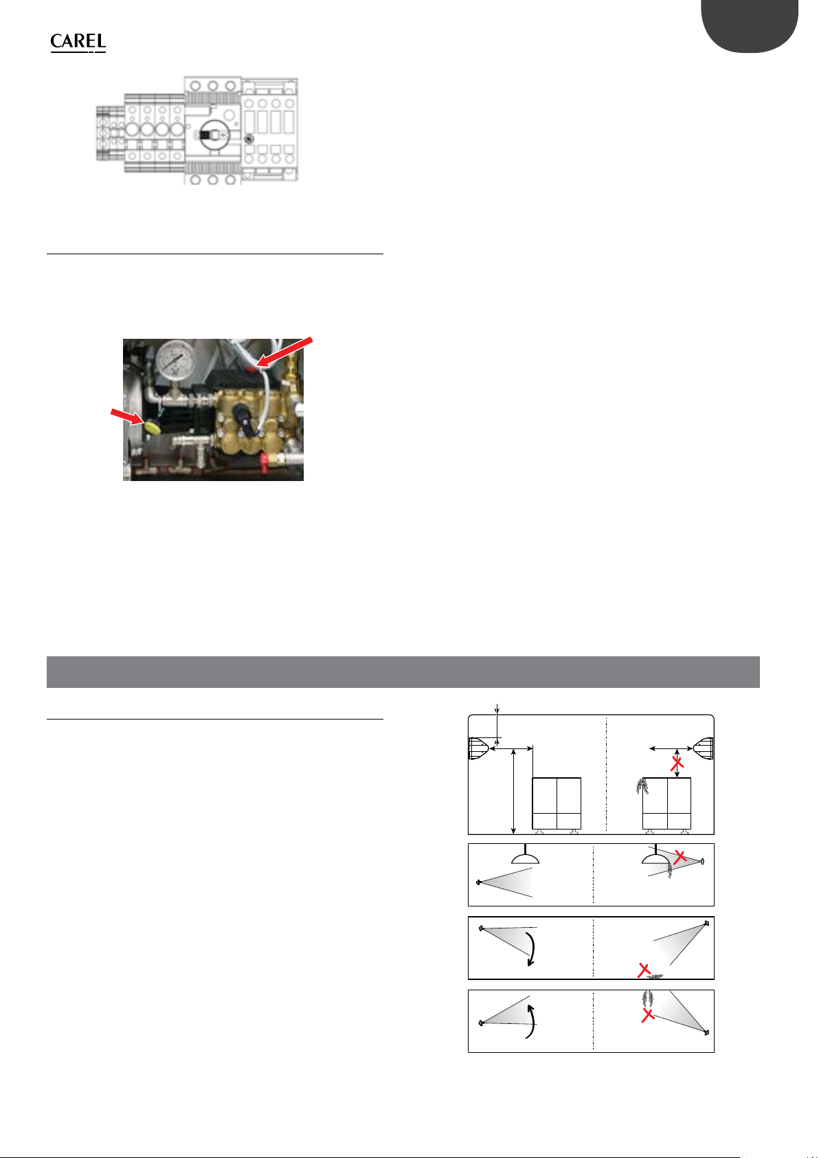
Fig. 2.h
2.4 Changing the oil cap
During installation, before starting the unit, remember to replace the red
oil cap (A) on the pump with the yellow one (B) supplied. The red cap is
closed and is only used for transport. The yellow cap has a vent opening
and is used for normal operation of the system. The yellow cap is supplied
inside the cabinet, tied to the high pressure gauge (see the image below).
A
B
ENG
Fig. 2.i
3. DISTRIBUTION SYSTEM INSTALLATION
3.1 Blower unit installation
The humiFog Direct system works by connecting the cabinet to a
number of blower units installed directly in the room to be humidied
and/or cooled.
The following simple rules must be kept in mind when installing the
blower units:
• the minimum ow-rate that can be atomised in the room is 8 l/h
(irrespective of the size of the pump). The minimum number of blower
units must therefore be dened based on the number and size of the
chosen nozzles.
The maximum numbers of blower units that can be connected to a
cabinet are:
• 12 blower units with 2 nozzles
• 6 blower units with 4 nozzles
• 3 blower units with 8 nozzles
The blower units must be suitably positioned so as to allow complete
absorption of the sprayed water. Consequently it is recommended to
install the blowers a due distance apart, at a sucient height from the
oor and with free space at the front without obstacles.
0.5 ÷ 1m
≥ 5m
≥ 4m
light light
≤ 10°
SI
SI NO
SI NO
NO
≥ 5m
≤ 4m
The blower units can be mounted either on the wall or on the ceiling.
For a correct installation, see the example in Fig. 3.a or contact Carel for
dierent temperature and humidity conditions.
13
≤ 10°
rH = 40% T = 25 °C
"humiFog direct" +0300073EN rel. 1.2 - 02.05.2019
SI NO
Fig. 3.a
ENG
The blower unit installation procedure is as follows:
1. Unpack the blower unit from the box it was delivered in. The blower
units are delivered fully assembled.
2. Remove the side plastic covers cover from the blower. Unscrew the
long screws on the side using a screwdriver. Make sure to keep the
screws, as they will be needed again for assembly at the end.
3. Mount the blower unit on the metal support. See paragraph 3.2 for
details.
4. Connect the water line to the inlet on the blower units (M16x1.5). See
paragraph 3.3 for details.
5. Electrically connect the blower units to the cabinet, which supplies
power and controls operation of the fans. See paragraph 3.4 for
details.
6. Complete blower assembly by repositioning the side plastic covers
removed previously, and xing them with the same screws as
removed at the beginning.
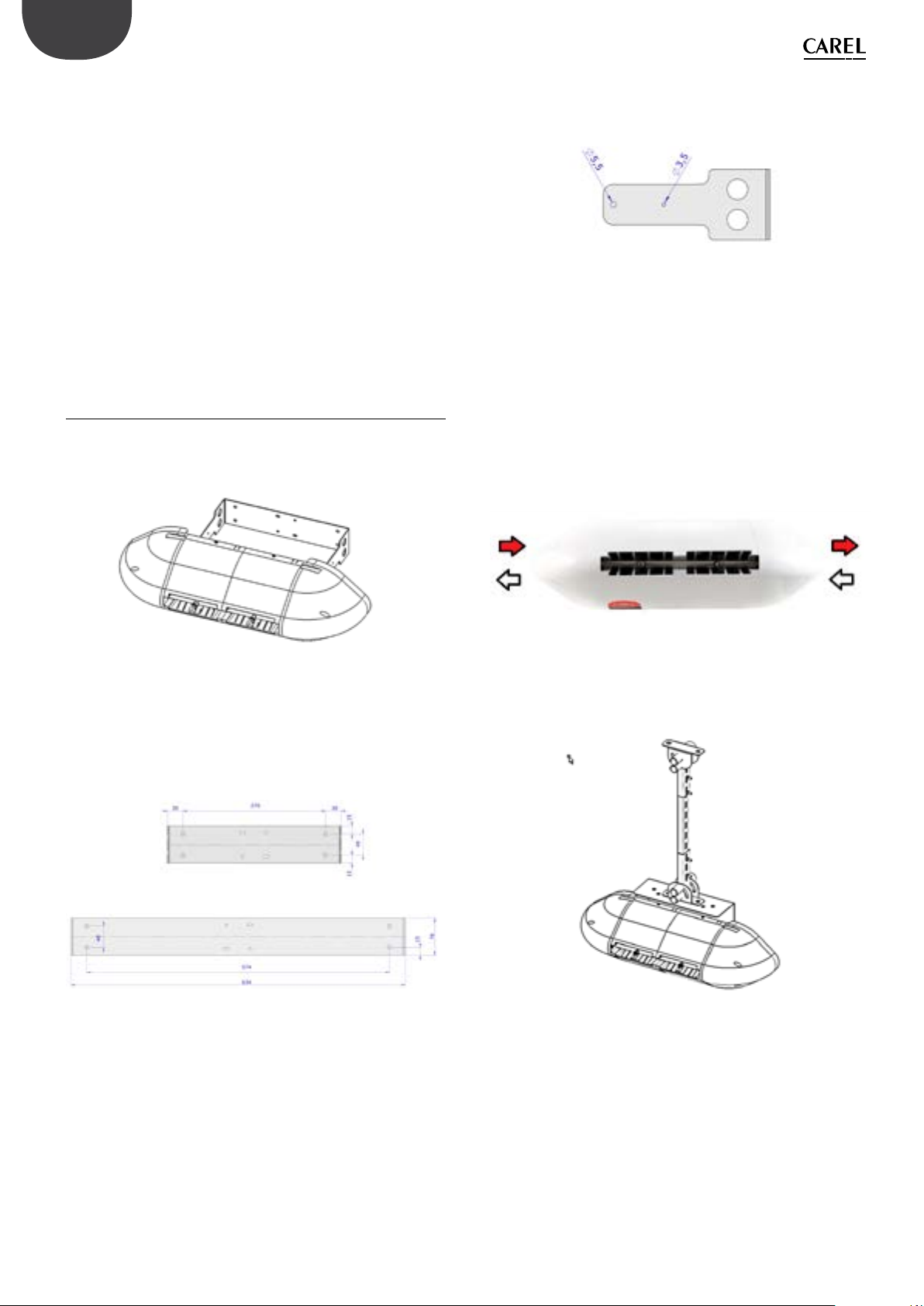
3.2 Mounting single blower units on the wall / ceiling
The single blower units (P/N DLA%F) are designed to be installed on a
vertical wall using a special metal support to be xed to the wall using
screws. Check that the wall is made from suitable material and is able to
support the weight of the blower unit (concrete, not plasterboard).
Then attach the blower to the protrusions on the wall-mounting support
bracket.
Fix the blower unit to the bracket using the screws supplied in a bag
inside the packaging.
Fig. 3.e
When tightening the rst screw (M6 self-tapping in Ø=5.5 mm holes),
slightly loosen the screws on the ring clamps that support the nozzle
manifold, so as to be able to turn it and free up space to continue
mounting the unit. Tighten one screw on the right and one screw on
the left.
Then tighten the third screw (M4 self-tapping in Ø=3.5 mm hole) on
the right-hand side of the blower (opposite the terminal block). When
tightening this screw, the angle of the blower can be adjusted between
-10°/-5°/0°/+5°/+10° from horizontal, using one of the ve small holes
provided.
Then make the water connections, connecting the feedwater line
either on the right or left of the blower, and the water return line on the
opposite side.
Fig. 3.b
First remove the blower unit from the packaging and take o the side
plastic covers. Remove the blower unit from the steel bracket on the rear.
Rest the bracket against the wall in the position where the blower will be
installed, and then drill four holes in the wall, using the steel bracket as
the drilling template.
Fig. 3.c
Fig. 3.d
After having drilled the holes in the wall, x the metal support using
anchor screws (not supplied).
Fig. 3.f
Finally, t the two cable glands and complete the electrical wiring, as
described in paragraph 3.4.
Carel also provides an additional kit (including a special plate bent at 90°)
for mounting single blower units on the ceiling.
Fig. 3.g
"humiFog direct" +0300073EN rel. 1.2 - 02.05.2019
14
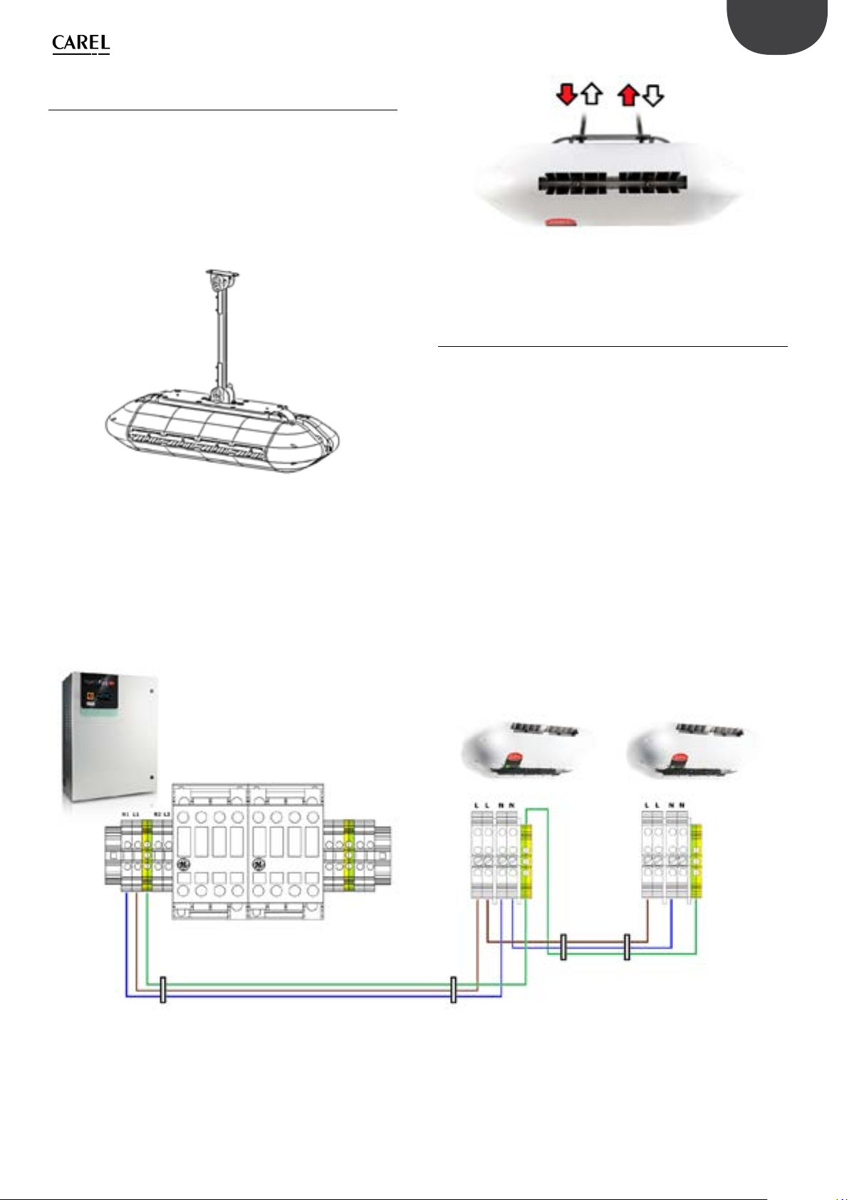
3.3 Mounting double blower units on the ceiling
The double blower units (P/N DLA%B) are designed to be installed on
the ceiling by anchoring them to a metal support that can support their
weight and the vibrations due to the pressurised water. To mount the
blower unit, use the special attachments provided on the unit’s metal
structure.
Carel provides additional kits with everything needed to complete
installation easily. Make sure to carefully choose the point where the
vertical support bar will be anchored. The support bar must not be longer
than 1 metre, so as to avoid excessive bending and vibrations.
Fig. 3.h
After installing the blower, make the water connections by connecting
the feedwater and return lines to the two pipes provided on the top of
the blower. The feedwater/return lines can be connected either to the
right or left.
ENG
Fig. 3.i
Finally, t the two cable glands and complete the electrical wiring, as
described in paragraph 3.4.
3.4 Blower unit electrical connection
The blower units must be electrically connected to the cabinet so that
they are activated only when there is a humidication request
Before electrically connecting the blower units to the cabinet, make sure
that the cable glands supplied with the cabinet and the blower units are
available. All connections to be made by the user (cabinet power supply,
blower unit power supply, probe connections, etc.) must be performed
by running the cables through the cable glands, and in accordance with
local safety standards.
Also check that the cable is the right size for the distance and voltages
used. Carel recommends an AWG14 or AWG12 cable, as shown in the
technical data at the end of the manual.
To connect power to the blower units, connect three suitably-sized wires
(line + neutral + earth) from the terminals on the cabinet (shown in the
gure) to the terminals on the blower (shown in the gure). To power
a second and subsequent blowers, start from the free terminals on of
the previous blower and connect to the terminals on the next blower, as
shown in the gure.
Fig. 3.j
Important:
• remember to run the wires through the cable glands (marked in the gure).
• check the maximum number of blower units that can be connected to each cabinet in the tables in Appendix 12 at the end of the manual.
• when connecting the line (L) and neutral (N) from the cabinet to the blower units, never reverse L and N. Reversing or crossing over the wiring may cause
short-circuits.
After having completed the wiring, close the side plastic covers again and x them using the screws. The system is now ready to operate.
15
"humiFog direct" +0300073EN rel. 1.2 - 02.05.2019

ENG
4. ELECTRONIC CONTROLLER SET UP AND CONNECTIONS
After having correctly installed the cabinet and completed the water and
electrical connections, connect the signals used to interface with the
humiFog Direct humidier to the c.pHC electronic controller (and the
c.pCO controller on two-zone cabinets.
Fig. 4.a
4.1 Remote ON/OFF signal connection
The remote ON/OFF contact is used to enable operation from an external
device. It is a digital contact that can be either open or closed: when the
terminal is open, humiFog cannot operate. The contact refers to inputs 7
[GND]- 8 [digit] on terminal M2 on the c.pHC.
The remote ON/OFF contact must not be confused with the ON/OFF
signal that manages operation, described in paragraph 4.5.
The following types of probes are allowed:
• 4-20 mA, 0-20 mA current probes
• 0-10 V, 0-1 V, 2-10 V voltage probes
The analogue signal from the limit probe in the rst zone is connected to
the c.pHC controller via inputs 5 [IN a] 6 [GND] 3 [+12 Vdc] on terminal M2.
MAIN PROBE
ZONE 1
[IN a] [GND] [+15 Vdc] [IN a] [GND] [+15 Vdc]
Important: if connecting a probe with voltage signal that requires a
power supply greater than the +12 Vdc supplied to the terminal on the
c.pHC, the third wire must not be connected to input 3 [+12 Vdc] but
rather to terminal GA1 [+24 Vac], made available on the cabinet terminal
block, right above the c.pHC.
LIMIT PROBE
ZONE 1
Fig. 4.c
7 [GND]8 [digit]
Fig. 4.b
If not intending to use an external contact to start / stop the unit, leave
the terminal short-circuited (as supplied).
REMOTE ONOFF
4.2 Analogue signal from the main probe
and limit probe in the first zone
humiFog Direct can be controlled using an analogue signal (modulating)
from a main humidity or temperature probe connected to the c.pHC
electronic controller. If connected to a humidity probe, humiFog Direct
will display the relative humidity read by the probe. If connected to a
temperature probe, on the other hand, humiFog Direct will display the
temperature. Based on the probe reading and the deviation from the set
point, humiFog Direct will modulate the humidication load according
to the PWM principle (see paragraph 6.2). The following types of probes
are allowed:
• 4-20 mA, 0-20 mA current probes
• 0-10 V, 0-1 V, 2-10 V voltage probes
The analogue signal from the main probe in the rst zone is connected to
the c.pHC controller via inputs 1 [IN a] 2 [GND] 3 [+12 Vdc] on terminal M2.
4.3 Analogue signal from the main probe and limit probe in the second zone
If a second zone is used (only with UA%DD201 and UA%DU201 cabinets),
the main probe corresponding to the second zone must be connected to
the c.pCOe expansion installed under the c.pHC controller.
The following types of probes are allowed:
• 4-20 mA, 0-20 mA current probes
• 0-10 V, 0-1 V, 2-10 V voltage probes
The inputs used for the main probe are U1 [IN a] and [GND] on terminal
J2, and the power supply is taken from the +Vdc on terminal J9. The limit
probe (optional) corresponding to the second zone is connected to
inputs U2 [IN a] and [GND] on terminal J2, and the power supply is taken
from the +Vdc on terminal J9.
MAIN PROBE
ZONE 1
[IN a] [GND] [+15 Vdc] [IN a] [GND] [+15 Vdc]
LIMIT PROBE
ZONE 1
The limit probe (optional) is used for the auxiliary function to reduce
humiFog Direct humidication or cooling capacity when approaching
a set humidity or temperature threshold (on the display or external
controller). To set the threshold, select operation with limit probe on the
display. The threshold will either be a humidity or temperature value. The
limit probe can also be used without using a main probe.
"humiFog direct" +0300073EN rel. 1.2 - 02.05.2019
Fig. 4.d
Important: unlike the rst zone, the connection to the c.pCOe expansion
relating to the second zone can supply power to probes that require up
to 21 Vdc.
16

ENG
4.4 Analogue signal from an ext. controller
As an alternative to the main probe, a signal from an external controller
can be used. The latter processes the request to send to humiFog Direct
via an analogue signal, which varies from 0 to 100%. humiFog will adjust
the capacity delivered proportionally to the signal received, and the
display will show the request sent as a percentage.
The following types of proportional signals are allowed:
• 4-20 mA, 0-20 mA current signals
• 0-10 V, 0-1 V, 2-10 V voltage signals
The external signal for the rst zone is connected to the c.pHC controller
via inputs 1 [IN a] and 2 [GND] on terminal M2.
The external signal for the second zone is connected to the c.pCOe
controller via inputs U1 [IN a] and [GND] on the terminal J2.
EXTERNAL SIGNAL ZONE 1
[IN a] [GND] [IN a] [GND]
The limit probes can also be associated with the external proportional
signal, and will be connected as shown in the previous paragraphs.
Fig. 4.e Fig. 4.f
EXTERNAL
SIGNAL ZONE 2
4.5 Digital signal from humidistat or external controller
The signal from the external controller can be replaced by the signal from
a humidistat, thermostat, or any external device with digital contact. In
this case, humiFog Direct will work in ON/OFF mode, either delivering
100% of ow-rate or remaining in standby. The capacity delivered can be
reduced by setting parameter P0 (the reduction is managed by PWM, see
paragraph 6.5). The electrical connection is the same as in the previous
case shown in Figure 4.e. Make sure to congure the humiFog Direct (via
the screens on the display) so that it can be controlled by an ON/OFF
signal from external controller or device.
4.6 Serial or Ethernet communication
humiFog Direct can be controlled by a supervisor that reads the humiFog
Direct parameters and sends commands. To connect a supervisor, the
RS485 serial port (terminal M12, inputs 1 [Tx/Rx-] 2 [Tx/Rx+] 3 [GND]) or
Ethernet port is used. The choice of which port to use depends on the
supervisor. Modbus and BACnet communication protocols are available
as standard: no auxiliary cards need to be tted on the c.pHC controller
The Ethernet port can also be used for the Webserver function (see
Chapter 8), so as to monitor and control humiFog Direct via a local
network, without needing a supervisor.
4.7 Alarm relay output
The digital output for communication of an alarm status is connected to
contacts 1-2-3 on terminal M6 on the c.pHC. N.C. logic is set by connecting
the two wires to contacts 1-2, while N.O. logic is set connecting the two
wires to contacts 1-3.
N.C.
ALARM RELAY
Fig. 4.h
N.O.
4.8 Unit status digital output
The c.pHC controller provides a digital output corresponding to unit status.
This is a voltage-free contact that provides the following information:
• contact closed: unit on or in standby
• contact open: unit o (OFF from keypad or from remote contact, or
no power)
The unit status digital output is available at contacts 1-2 on terminal M5
on the c.pHC.
4.9 Production percentage analogue
outputs
The c.pHC controller provides an analogue output (0-10 V) corresponding
to the percentage of production that humiFog Direct is delivering.
The output replicates the request signal relating to the corresponding
humiFog Direct zone.
The production percentage analogue outputs are connected to the
following terminals:
• zone 1: outputs 1 and 2 on terminal M8 on the c.pHC.
• zone 2: outputs U3 and GND on terminal J2 on the c.pCOe.
ETHERNET
Fig. 4.g
1 [Tx/Rx-]
2 [Tx/Rx+]
3 [GND]
SERIAL RS485
% PRODUCTION
ZONE 1
Important: when several GND contacts are wired to the same terminal
these are equivalent to each other, and can be used indierently.
17
SYSTEM
STATUS
Fig. 4.i Fig. 4.j
"humiFog direct" +0300073EN rel. 1.2 - 02.05.2019
% PRODUCTION
ZONE 2

ENG
5. STARTUP AND USER INTERFACE
5.1 Graphic terminal
The 4.3” touch graphic terminal has an interface with coloured and
animated icons. The contents of the display can be scrolled up and down
simply and intuitively.
Fig. 5.a
On the right of the graphic terminal is the notication bar.
If the humidier is powered on, the notication bar is always on, even when
the display is o, and provides immediate information on humidier status.
Bar colour Bar status Humidier status
White Light on steady Unit o (o or standby)
Green Light on steady Unit in production, start-up, ll
Blue Light on steady Washing in progress
Red Light ashing Alarm on the unit
Cyan Light on steady Unit in manual mode
Yellow Light ashing Unit shutting down
Tab. 5.a
5.2 Start-up
Switch on humiFog Direct by moving the disconnect
switch on the front panel from position O to position
I.
The display shows the “humiFog Direct” logo, after which the menu
language can be chosen, from the following options:
• English
• Italiano
• Deutsch
• Français
• Español
Tap the language and ag icon with your nger to access the drop-down
menu with the options.
Configuration wizard
When starting the rst time, a wizard is provided to quickly set the main
unit parameters. There are at most 10 steps to set up the unit:
Step 1/10
Enter the humidier model.
Step 2/10
Enter the humidication load in kg/h for zone 1 and, if present, zone
2. The humidication load can be easily calculated by multiplying the
number of atomising nozzles in the zone by the ow-rate delivered by
each nozzle.
Step 3/10
Select zone 1 control mode from the options:
• ON/OFF contact (e.g. humidistat);
• External signal:
• External signal + humidity limit probe;
• External signal + temperature limit probe;
• Main humidity probe;
• Main temperature probe;
• Main humidity probe + humidity limit probe;
• Main temperature probe + temperature limit probe;
• Main humidity probe + temperature limit probe;
• Main temperature probe + humidity limit probe;
• Two main humidity probes (weighted average);
• Two main temperature probes (weighted average);
If using wireless probes, select the parameter that is shown by default
and at the end of the wizard refer to chapter “9. WIRELESS PROBES;
INSTALLATION AND CONFIGURATION”.
Step 4/10
Select zone 2 control mode. The options available are those already listed
in step 3/10.
Step 5/10
Select the type of signal from the main probe or from an external
controller to control zone 1:
• 0-10 V;
• 4-20 mA;
• 0-20 mA;
• 0-1 V;
• 2-10 V;
• NTC (temperature probe only)
Fig. 5.b
Scroll the menu with your nger.
Select the desired language and then conrm.
Fig. 5.c
"humiFog direct" +0300073EN rel. 1.2 - 02.05.2019
Step 6/10
Select the type of signal from the limit probe in zone 1. The signals
available are those already listed in step 5/10.
Step 7/10
Select the type of signal from the main probe or from an external
controller to control zone 2. The signals available are those already listed
in step 5/10.
Step 8/10
Select the type of signal from the limit probe in zone 2. The signals
available are those already listed in step 5/10.
Step 9/10
Enter the set points for zone 1 and zone 2 relating to the main probe and
limit probe.
Step 10/10
Enter the system date and time.
The wizard is now nished: you can choose whether or not to display it
the next time humiFog direct is powered on. In any case, the wizard is
always accessible from the settings menu on the graphic terminal.
18

ENG
5.3 Touch display
HOME menu
The “HOME” menu includes information about the pumping station and
the zones, including current production, information on the probes and
unit status.
10
8 9
11
1
2
Pos. Function Pos. Function
1 ON/OFF quick menu 7 Notication centre
2 Set point quick menu 8 System date & time
3 Input/output quick menu 9 Scheduler status
4 System information quick menu 10 Master/Slave Network
5 Descriptive icon of zone status 11 Main menu
6 Alarm list
Fig. 5.d
5.3.1 ON/OFF quick menu
Pressing the ON/OFF quick menu icon accesses the screen for switching
the entire system or individual zones on and o. To switch on or o the
unit or zones (ON when the indicator is positioned to the right, OFF when
positioned to the left), press the button.
Message Values Meaning
Unit ON Enables the pump to operate according to zone request
Zone 1/2
(visible only
if unit ON)
The menu also contains information on the type of system start-up
control signal. To return to the home menu, press the “HOME” icon
OFF Switches the pumping unit OFF
START Enables atomisation in zone 1/2 according to the request
PAUSE Temporarily stop atomisation in zone 1/2
7
6
5
4
3
Tab. 5.b
Tab. 5.a
To return to the home menu, press the “HOME” icon
Fig. 5.f
5.3.3 INPUT/OUTPUT quick menu
Press the icon to access the menu.
The input/output dashboard oers an intuitive and real-time view of the
system operating status, the values read by the humiFog direct cabinet
probes, the status of the mechanical components in the water circuit and
the water ow path.
Mechanical component I/O dashboard
Solenoid valve
Pressure sensor
Temperature sensor
Pressure switch
Pump
Nozzles
To return to the home menu, press the “HOME” icon
symbol
(Valve closed)
(Valve open)
(Atomise ON
(Atomise OFF)
System components
FV: cabinet ll valve
BYP: bypass valve
DC: cabinet drain valve
FV1: zone 1 ll valve
DR1: zone 1 drain valve
FV2: zone 2 ll valve
DR2: zone 2 drain valve
LPS: low pressure sensor
RHP: high pressure sensor
T: water temperature sensor
HP: high pressure switch
Cabinet pump
Zone nozzles
Tab. 5.d
Fig. 5.e
5.3.2 Set point quick menu
Press the icon to access the menu. The menu is used to modify the set
point and proportional control band. Press the white number to change
the value. Enter the desired value and press the conrm button (
Title Message Values Default
Zone 1 set
(Zone 2 set)
To move from one area to another, or from one page to another, press
the right and left arrows on the display and repeat the same operations
to change the values.
Main probe set point 0-100% rH 0-40 °C 50% rH 25 °C
Main probe band 0-10% rH 0-10 °C 5% rH 2 °C
Limit probe set point 0-100% rH 0-40 °C 80% rH 15 °C
Limit probe band 0-10% rH 0-10 °C 5% rH 2 °C
).
Tab. 5.c
Fig. 5.g
To switch to display the input/output values in table form, press the right
arrow.
If using wireless probes, to display the input/output values, press the
right arrow again.
Use the slider to scroll through the table.
To return to the previous display, press
To return to the home menu, press the “HOME” icon
Fig. 5.h
19
"humiFog direct" +0300073EN rel. 1.2 - 02.05.2019

ENG
Fig. 5.i
5.3.4 INFO quick menu
Press the icon to access the menu.
Menu describing humidier status, software and hardware information.
To move from one page to another, press the arrows on the right and left
of the display.
To scroll through the displayed information, press the slider.
To return to the home menu, press the “HOME” icon
5.3.7 Notification centre
Press the icon to access the notication centre.
To view the details of an individual notication, press the notication.
To return to the previous display, press
To return to the home menu, press the “HOME” icon
Fig. 5.m
5.3.8 System date and time
The system date and time is displayed.
5.3.9 Scheduler status
If enabled, the scheduler status (on/o ) is shown. Pressing the icon
accesses the scheduler section, described in the following paragraph
“5.3.16 Scheduler”.
Fig. 5.j
5.3.5 Zone status
To view more details for the single zone, on the display home page press
the white nozzle icon or use the arrows on the right and left of the display
to move from one zone to the other.
To return to the home menu, press the “HOME” icon
Fig. 5.k
5.3.6 Alarm list
Press the icon to display the alarm list.
To view the alarm log, press
To reset the alarms, press
To return to the previous display, press
To return to the home menu, press the “HOME” icon
5.3.10 MASTER/SLAVE Network
Only for single-zone cabinets, if the master/slave network is enabled for
several humidiers, the
letter M is displayed, for slave units the letter S is displayed.
Press the icon to access information from the humidier network.
The page displayed shows some of the characteristics of the individual
unit and the system.
To quickly display the IP addresses of the units making up the master/
slave network, press
To view the page with details on current production and the status of the
humidiers in the master/slave network, press the right arrow.
icon is displayed. For the master unit, the
Fig. 5.n
.
Fig. 5.l
"humiFog direct" +0300073EN rel. 1.2 - 02.05.2019
Fig. 5.o
To access information on the individual humidier, press the desired unit.
20

ENG
5.3.11 Main menu
Press the icon to access the main menu.
The menu provides access to the system items that are available without
entering a password.
To return to the previous display, press
To return to the home menu, press the “HOME” icon
Fig. 5.p
Description of the menus:
Menu Description
Clock Date and time setting
Input/Output Display the analogue and digital inputs/outputs
Graphs Display historical and real-time operation of the
humidier
Functions Special and manual functions
Scheduler Manage scheduling of working time bands
Language Set the menu language
Settings Access advanced humidier conguration (Installer
password 77). Menu: E. Settings. Change unit of measure
(Imperial/International)
Tab. 5.e
5.3.12 Clock
Press the icon to access the function.
Press the text to change the desired parameters.
To return to the previous display, press
To return to the home menu, press the “HOME” icon
5.3.14 Graphs
Press the icon to access the function.
The graphs function is used to view the values of some system analogue
and digital variables over a certain time frame.
Press the zone to be viewed.
On the rst screen displayed, the real-time value of the analogue and
digital variables relating to the zone is plotted. The value of each variable
is shown numerically in the table to the right of the graphs.
To scroll through the displayed information, press the slider.
To return to the previous display, press
To return to the home menu, press the “HOME” icon
Fig. 5.r
To move from one page to another, press the arrows on the right and left
of the display.
Moving to the right, the second screen displays the history of analogue
variables for the zone.
Press the
Press the
Press the
Press the arrows under the graph to change the period displayed.
Press the
the red cursor. The value of the variables corresponding to the red cursor
is shown in the table on the right.
icon to save the graph displayed to external memory.
icon to restore the initial view.
icon to select the length of the period to be viewed.
icon to hide the variables, magnify the graph and move
Fig. 5.q
5.3.13 Input/Output
Press the icon to access the function.
The same screen is displayed, which is also accessible from the input/
output quick menu.
Fig. 5.s
Moving to the right again, the history of the system's digital variables is
displayed on the third screen.
Fig. 5.t
21
"humiFog direct" +0300073EN rel. 1.2 - 02.05.2019

ENG
5.3.15 Functions
Press the icon to access the functions.
The option to select the language following a reboot or unit power on
can be enabled or disabled.
To return to the previous display, press
To return to the home menu, press the “HOME” icon
Fig. 5.u
5.3.16 Scheduler
Press the icon to access the function.
Press the
Press the
To return to the previous display, press
To return to the home menu, press the “HOME” icon
icon to activate or deactivate the scheduler function
icon to access scheduler programming
5.3.18 Settings
Press the icon to access the function.
Enter the password (installer password 77) and conrm.
To return to the previous display, press
To return to the home menu, press the “HOME” icon
Fig. 5.y
Type in the
Press the icon to update the display application from a USB pendrive
Press the
Press the
Press the
The advanced conguration is managed via a keyboard on the display
(g. 5.a).
For details on the advanced conguration screens and parameters, see
the next chapter.
icon to change the unit of measure.
icon to access the conguration wizard or factory data reset
icon to access the advanced conguration.
icon to log out.
Fig. 5.v
The display shows the weekly scheduling status, press the column with
the individual day to access programming
Fig. 5.w
Press the
arrows to move to the previous or next day. Press the
scheduler program to the next day.
icon to program the scheduler time and status. Use the
icon to copy the
87
1
2
3
Fig. 5.z
Button Function
(1) alarm list and reset any active alarms
(2) PRG return to the “main” screen
from the “main” screen, access the previous menu
(3) ESC return to the previous screen/display
access notications (from main menu only)
(4) UP cyclically scroll the screen menu, parameters and param-
eter values
from the “main” screen: access the INFO screens
(5) ENTER select and conrm
from the main menu: access the “SET” screens
(6) DOWN cyclically scroll the screen menu, parameters and param-
eter values
from the “main” screen: access the INFO screens
(7) multiple selection of the previous buttons
(8) multiple selection duration
4
5
6
Tab. 5.f
Fig. 5.x
5.3.17 Language
Press the icon to access the function.
Scroll with your nger and select the desired language.
"humiFog direct" +0300073EN rel. 1.2 - 02.05.2019
5.4 Remote installation of the touch display
To install the 4.3” touch screen in a remote position, use kit P/N
HCTXDA0000. The kit comprises a touch display, a 24 Vdc power supply,
a telephone cable and a telephone splitter for simultaneous connection
of the two displays (one in the remote position and the other installed on
the humidier).
22

ENG
6. ADVANCED CONFIGURATION PARAMETERS AND
OPERATING OPTIONS
6.1 Main menu and overview of functions
When accessing with password 77, the advanced settings button is available
for accessing a series of additional submenus. Each submenu is divided into a
number of screens identied by the index shown at the top right on the display.
The table below provides a complete overview of the screens.
Menu Index Description
a. Control
b. Functions
c. Congurations
d. Network unit Dd01 Enable the humidier network using the PRG button (if enabled, the network symbol appears on the main screen)
e. Manual mode De01 Enable manual zone request, set request % and enable management of individual c.phc outputs to check operation of electro-
Da01 Set the type of control in zone 1 and the maximum production
Da02 Set the type of control in zone 2 and the maximum production
Da03 (visible if control using two main probes has been enabled)
Set the weight of the zone 1 control probes
Da04 Set the set point and band for the zone 1 main probe
Da05 Set the set point and band for the zone 1 limit probe
Da06 (visible if control using two main probes has been enabled)
Set the weight of the zone 2 control probes
Da07 Set the set point and band for the zone 2 main probe
Da08 Set the set point and band for the zone 2 limit probe
Da09 Maintenance hour counter, reset counter and maintenance warning
Da10 This is shown after 40 operating hours
The oil change counter (warning at 50 h) can be reset
Da11 Unit hour counter (not resettable)
Da12 Set unit operating hours (e.g. after replacing c.phc controller) and maintenance warning
Db01 Enable lling and set the lling time
Db02 Set washing cycle duration and frequency
Db03 Enable management of the external water treatment system
Db04 Management of advance start and delayed stop of blower fans
Db05 Export event log via USB
Db06 Export alarm log via USB
Dc01 Set the type of signal for the main humidity probe in zone 1, minimum/maximum probe reading, probe oset, enable
disconnected probe alarm and set the alarm delay
Dc02 Set the type of signal for the main temperature probe in zone 1, minimum/maximum probe reading, probe oset, enable
disconnected probe alarm and set the alarm delay
Dc03 Set the type of external signal for zone 1, minimum/maximum signal value, signal oset
Dc04 Set the NO/NC logic for the external on/o contact (humidistat)
Dc05 Set the type of signal for the humidity limit probe in zone 1, minimum/maximum probe reading, probe oset, enable
disconnected probe alarm and set the alarm delay
Dc06 Set the type of signal for the temperature limit probe in zone 1, minimum/maximum probe reading, probe oset, enable
disconnected probe alarm and set the alarm delay
Dc07 Set the type of signal for the main humidity probe in zone 2, minimum/maximum probe reading, probe oset, enable
disconnected probe alarm and set the alarm delay
Dc08 Set the type of signal for the main temperature probe in zone 2, minimum/maximum probe reading, probe oset, enable
disconnected probe alarm and set the alarm delay
Dc09 Set the type of external signal for zone 2, minimum/maximum signal value, signal oset
Dc10 Set the NO/NC logic for the external on/o contact (humidistat)
Dc11 Set the type of signal for the humidity limit probe in zone 2, minimum/maximum probe reading, probe oset, enable
disconnected probe alarm and set the alarm delay
Dc12 Set the type of signal for the temperature limit probe in zone 2, minimum/maximum probe reading, probe oset, enable
disconnected probe alarm and set the alarm delay
Dc13 (visible for single-zone cabinet)
Set wireless probes 1-4: main, limit or absent
Dc14 (visible for single-zone cabinet)
Set wireless probes 5-8: main, limit or absent
Dc15 (visible for two-zone cabinet)
Enable wireless probes 1-4 for the main/limit control function in zone 1/2
Dc16 (visible for two-zone cabinet)
Enable wireless probes 5-8 for main/limit control function in zone 1/2
Dc17 Set the percentage weight of the wireless probes
Dc18 Set humidication load in zone 1/2
Dc19 Set the pressure relief time for zone 1
Dc20 Set the pressure relief time for zone 2
Dc21 (visible for two-zone cabinet)
Set the system anti-drip time
Dc22 Set the anti-pressure return time
Dc23 Set the cabinet pressure probe osets
Dd02 Set the IP address of cabinet 1/2/3/4 in the network and check status, online/oine
Dd03 Set maximum load and grouped/balanced distribution set point
Dd04 Set cabinet rotation time (0 h = rotation disabled)
Dd05 Unit oine alarm timeout
Dd06 Disable network settings for the current unit (if Y, the network symbol is not shown on the main screen)
Dd07 Current unit production request
Dd08 Check status and production % of unit 1/2/3/4 on the network
mechanical components
De02 Manual management of contactor, ll valve FV, cabinet drain valve DR, bypass valve BYP
23
"humiFog direct" +0300073EN rel. 1.2 - 02.05.2019

ENG
Steam_Pr
St
Menu Index Description
e. Manual mode De03 Manual management of zone 1 ll valve FV1, zone 1 drain valve DR1, zone 1 fans, set zone 1 production %
f. Initialisation Df01 Set the screen language
g. Supervision Dg01 (visible for single-zone cabinet)
h. Logout Exit the settings menu: request password on next access
6.2 Control
6.2.1 Modulation of production
The system modulates the atomisation of water intermittently, in PWM
mode (pulse width modulation). Within a time period of 120 seconds
(settable value), the unit will deliver pressurised water to the blower
units for atomisation by the nozzles in the room:
• for 120 seconds continuously, when there is maximum production
request;
• for a fraction of time Ton less than 120 seconds (minimum 8% of the
entire period) and proportional to the request signal, if not at the
maximum.
When atomisation stops, the pump remains active and the water is
recirculated through an internal bypass circuit in the pumping unit,
rather than being delivered to the blower units.
De04 Manual management of zone 2 ll valve FV2, zone 2 drain valve DR2, zone 2 fans, set zone 2 production %
De05 Manual management of unit status contact, alarm relay, cabinet fan, WTS contact
Df02 Change passwords for accessing the menus
Df03 Set the unit of measure (International or Imperial).
Df04 Set the unit model
Df05 Enable USB port reading for unit software update
Dg02 (visible for two-zone cabinet)
Dg03 Select supervisor protocol
Dg04 BMS supervisor port conguration: baud rate, stop bits, parity
Dg05 Ethernet supervisor port conguration: DHCP, IP address, mask, gateway, DNS. Important - these values must be provided by the
Dg06 BACnet conguration: address, maximum number of masters, maximum number of frames
Set the serial address, enable unit on/o and control from supervisor
Set the serial address, enable unit on/o and control from supervisor
local network administrator
Pmax
Steam_Pr
Pmin
OFF ON
0%
hy 2xhy 100%
Fig. 6.aa
Key:
Water_pr Pressurised water production Y External signal
P0 Max production hy Activation hysteresis
Pm Min production
Y= 0…1Vdc
0…10Vdc
2…10Vdc
0…20mA
4…20mA
Y
Tab. 6.a
Fig. 6.z
The type of control is set on the following screen:
Index Description Parameter
Type of control Set the type of control
Da01
Da02
Default: humidity (one probe)
Options: proportional to external signal,
proportional to external signal with limit
probe, On/O signal, humidity (one probe),
temperature (one probe), humidity with limit,
temperature with limit, humidity (two probes),
temperature (two probes)
Tab. 6.b
6.2.2 Proportional control to an external signal
(modulating operation)
Atomisation is proportional to the value of an external signal Y, (selectable
from the following options: 0 to 1 Vdc; 0 to 10 Vdc; 2 to 10 Vdc; 0 to 20
mA; 4 to 20 mA). The maximum production Pmax corresponds to the
maximum value of the external signal Y, and will be the humidier’s rated
production. The activation hysteresis hy is not settable by the user.
6.2.3 Autonomous control with humidity or
temperature probes
When using a main humidity control probe and an optional limit
humidity probe, atomisation is related to the % rH reading made by the
relative humidity probe and increases as the value read deviates from the
set point St. Maximum production Pmax corresponds to the case where
the humidity value, read by the probe, is BP away (proportional band)
from the set point. The activation hysteresis hy is not settable by the user.
Pmax
Pmin
ON
BP
Fig. 6.ab
Key:
Water_pr Pressurised water production Y External signal
P0 Max production hy Activation hysteresis
Pm Min production
OFF
hy
%rH
"humiFog direct" +0300073EN rel. 1.2 - 02.05.2019
24

ENG
When using a main temperature control probe and an optional limit
temperature probe, atomisation is related to the temperature reading in
°C or °F made by the probe and increases as the value read deviates from
the set point St. Maximum production Pmax corresponds to the case
where the temperature value, read by the probe, is BP away (proportional
band) from the set point. The activation hysteresis hy is not settable by
the user.
Fig. 6.ac
Key:
Water_pr Pressurised water production Y External signal
P0 Max production hy Activation hysteresis
Pm Min production
For “humidity (one probe)” or “temperature (one probe)” control, one
single main probe can be connected and congured, either wired or
wireless.
For “humidity with limit” or “temperature with limit” control, a wired
probe can be connected as the main probe and a wired probe as the
limit. If using wireless probes (maximum of four), two groups of probes
can be dened: the group of main probes and the group of limit probes.
In this case, the average will be calculated between the main probes,
depending on the dened weight, and the limit probes will also have
their own average, again depending on the dened weight.
For “humidity (two probes)“ or “temperature (two probes)” control, only a
group of main probes can be dened. Wired probes can be connected to
the main probe input (M2.1) and the limit probe input (M2.5), which will
be used as a second probe, with the average calculated. If using wireless
probes (maximum of four), only a group of main probes can be dened,
with the average calculated, depending on the dened weight.
For the connections of the signals and/or probes, see chap. 4.
6.2.4 Weighted average of the probes (installer
menu)
If using two temperature probes or two humidity probes, the humidier
controller will calculate the weighted average of the probe readings.
In this way, two probes can be used, for example humidity probes, at
opposite ends of the room, calculating the average.
Index Description Parameter
Da03
Da06
The weight of each probe should be expressed with a value from 0 to
100.
Weight of the
probes
Set the weight of the probes
Default: 100
Possible settings: 0 to 100
Step: 1
6.3 Functions
6.3.1 Filling
For correct functioning of the system there must be no air in the lines,
so as to avoid vibrations, long transients and low-quality atomisation. To
eliminate all air, the lling time must be set correctly. When starting the
system the rst time, measure the time required for the water to reach
the end of the circuit, and wait only until water visibly comes out of the
circuit. The longer the water circuit, the higher the lling time needs to
be.
Ref. Display Description Range Def UoM
Db01 En. lling When the pumping station
Duration Line lling time before start-
needs to start and the water
supply line is detected as
being empty, i.e. when rst
starting, enabling the pump,
starting again for the new
season etc., by setting the
parameter to Yes, the pump
delivers the ow-rate for
the time dened by the
following parameter, so as to
ll the line before atomisation
commences
ing atomisation, only if the
water supply line is detected
as beeing empty
6.3.2 Washing
The washing function involves ushing all of the water pipes for a set
time. The purpose is to completely wash the system and avoid stagnation.
Ref. Display Description Range Def UoM
Db02 Washing:
periodical
daily
Disable
washing
Interval
Time
Duration
Duration
washing carried out after
a set number of hours of
inactivity.
Washing performed daily at a
predened time
Washing disabled
Number of hours of inactivity after which a periodical
washing cycle is performed
Time of day when the daily
washing cycle is performed
Periodical washing cycle time
in minutes
Daily washing cycle time in
minutes
6.3.3 Blower fan management
The blower fans that atomise the water can be started before atomisation
commences, so as to reach an air ow that can support atomisation
when this starts.
A delay can be set for stopping the fans when atomisation ends, so as to
guarantee air ow immediately after the end of atomisation.
Ref. Display Description Range Def UoM
Db04 On ad-
vance
O delay Delay in stopping fans after
Start fans in advance before
starting atomisation
atomisation ends
Yes/No Yes
1/60 2 min
periodical
daily
disabled
0/99
0/24
0/60
0/60
0-10 3 s
3-120 10 s
periodical
120h
4 min
Tab. 6.c
type
h
Tab. 6.d
Tab. 6.e
The weighted average is calculated as follows:
Weighted average = ((S1×p1)+(S2×p2))
----------------------------
(p1+p2)
where “Si” is the probe reading, and “pi” the relative weight.
To calculate the arithmetic average, equal weights should be set (for
example: p1 = p2 = 100).
25
"humiFog direct" +0300073EN rel. 1.2 - 02.05.2019

ENG
6.4 Configurations
6.4.1 Main humidity probe setting
The main probe can be congured on screen index Dc01 for the singlezone and Dc07 for two-zone cabinets.
Index Description Parameter
Main probe Main probe conguration
Dc01
Dc07
For each probe, after having specied the type, the minimum and
maximum values readable can be dened, as well as an “oset” to
compensate for any imprecisions in the value read (example: oset =
3% rH corresponds to a 3 percent increase in the humidity value read by
the probe). The "En. Al." parameter enables the alarms corresponding to
probe faults. If a fault is detected for longer than the value of the "Delay"
parameter (seconds), the "main probe broken or disconnected" alarm will
be activated.
6.4.2 Main temperature probe setting
The main probe can be congured on screen index Dc02 for the singlezone and Dc08 for two-zone cabinets.
Index Description Parameter
Main probe Main probe conguration
Dc02
Dc08
For each probe, after having specied the type, the minimum and
maximum values readable can be dened, as well as an “oset” to
compensate for any imprecisions in the value read (example: oset =
3% rH corresponds to a 3 percent increase in the humidity value read by
the probe). The "En. Al." parameter enables the alarms corresponding to
probe faults. If a fault is detected for longer than the value of the "Delay"
parameter (seconds), the "main probe broken or disconnected" alarm will
be activated.
Default: Enable: Enabled (depending on the
type of control)
Type: 0-10 V
Minimum: 0% rH - Maximum: 100% rH
Oset: 0
En. Al (enable alarms): Yes
Del: 60 seconds
Possible settings:
Type 0-10 V/0-1 V/NTC/4-20 mA/0-20 mA/2-10
V
Minimum: 0-100% rH - Maximum: 0-100% rH
Oset: 0
En. Al (enable alarms): Yes
Del: 0-600 seconds
Tab. 6.f
Default: Enable: Enabled (depending on the
type of control)
Type: 0-10 V
Minimum: 0°C - Maximum: 60°C
Oset: 0
En. Al (enable alarms): Yes
Del: 60 seconds
Possible settings:
Type 0-10 V/0-1 V/NTC/4-20 mA/0-20 mA/2-10
V
Minimum: 0-60°C - Maximum: 0-100°C
Oset: 0
En. Al (enable alarms): Yes
Del: 0-600 seconds
Tab. 6.g
6.4.3 External signal setting
The type of external signal can be congured on screen index Dc03 for
the single-zone and Dc09 for two-zone cabinets.
Index Description Parameter
Main probe Main probe conguration
Dc03
Dc09
Default: Enable: Enabled (depending on the
type of control)
Type: 0-10 V
Minimum: 0 - Maximum: 100
Oset: 0
En. Al (enable alarms): Yes
Del: 60 seconds
Possible settings:
Type 0-10 V/0-1 V/4-20 mA/0-20 mA/2-10 V
Minimum: 0-100 - Maximum: 0-100
Oset: 0
En. Al (enable alarms): Yes
Del: 0-600 seconds
Tab. 6.h
6.4.4 Humidity limit probe setting
The limit probe can be congured on screen index Dc05 for the singlezone and Dc11 for two-zone cabinets.
Index Description Parameter
Main probe Main probe conguration
Dc05
Dc11
Default: Enable: Enabled (depending on the
type of control)
Type: 0-10 V
Minimum: 0% rH - Maximum: 100% rH
Oset: 0
En. Al (enable alarms): Yes
Del: 60 seconds
Possible settings:
Type 0-10 V/0-1 V/NTC/4-20 mA/0-20 mA/2-10
V
Minimum: 0-100% rH - Maximum: 0-100% rH
Oset: 0
En. Al (enable alarms): Yes
Del: 0-999 seconds
Tab. 6.i
For each probe, after having specied the type, the minimum and
maximum values readable can be dened, as well as an “oset” to
compensate for any imprecisions in the value read (example: oset =
3% rH corresponds to a 3 percent increase in the humidity value read by
the probe). The "En. Al." parameter enables the alarms corresponding to
probe faults. If a fault is detected for longer than the value of the "Delay"
parameter (seconds), the "main probe broken or disconnected" alarm will
be activated.
6.4.5 Temperature limit probe setting
The limit probe can be congured on screen index Dc06 for the singlezone and Dc12 for two-zone cabinets.
Index Description Parameter
Main probe Main probe conguration
Dc06
Dc12
Default: Enable: Enabled (depending on the
type of control)
Type: 0-10 V
Minimum: 0°C - Maximum: 60°C
Oset: 0
En. Al (enable alarms): Yes
Del: 60 seconds
Possible settings:
Type 0-10 V/0-1 V/NTC/4-20 mA/0-20 mA/2-10
V
Minimum: 0-60°C - Maximum: 0-100°C
Oset: 0
En. Al (enable alarms): Yes
Del: 0-600 seconds
Tab. 6.j
"humiFog direct" +0300073EN rel. 1.2 - 02.05.2019
26

For each probe, after having specied the type, the minimum and
maximum values readable can be dened, as well as an “oset” to
compensate for any imprecisions in the value read (example: oset =
3% rH corresponds to a 3 percent increase in the humidity value read by
the probe). The "En. Al." parameter enables the alarms corresponding to
probe faults. If a fault is detected for longer than the value of the "Delay"
parameter (seconds), the "main probe broken or disconnected" alarm will
be activated.
6.4.6 Pressure relief time setting
In the event of poor atomisation quality or dripping in the nal
atomisation phase after a modulation period (Ton), the pressure relief
time can be adjusted, increasing it as much as necessary. The required
delay increases according to the length of the high pressure water line.
Increasing this time may mean the anti-dripping time also needs to be
adjusted, for two-zone systems. Always check correct operation of the
atomisation on and o phases in PWM modulation mode.
Ref. Display Description Range Def. UoM
Dc19
Dc20
Pressure relief
time
Line pressure dissipation
when atomisation o
0-30 5 s
Tab. 6.k
ENG
6.4.7 Anti-dripping time setting
For two-zone cabinets poor atomisation quality in the initial atomisation
phase after a modulation period (To ), the anti-dripping time can be
adjusted, increasing it as much as necessary. The required delay increases
according to the length of the high pressure water line and the setting of
the pressure relief parameter.
Ref. Display Description Range Def. UoM
Dc21 Anti-dripping
time
Fill line
when starting
atomisation
0-30 0 s
Tab. 6.l
6.4.8 Anti-pressure return time setting
In the event of alarm ABA05: high bypass pressure, slightly increase
the anti-pressure return time to allow better pressure dissipation in the
cabinet.
Ref. Display Description Range Def. UoM
Dc22 Anti-pressure
return
Dissipation of
cabinet pressure
0.2-30 1.7 s
Tab. 6.m
27
"humiFog direct" +0300073EN rel. 1.2 - 02.05.2019

ENG
Master
Slave
Master
Slave
Slave
M2M9 M8 M1 M5 M6M12
1 1 2 3 4 5 6 7 82 1 13 2 31 22 1 2 1 2
Master
Slave
Slave
sonda principale
o segnale esterno
7. MASTER/SLAVE NETWORK OF HUMIDIFIERS
7.1 Description of the Master/Slave system
To extend humidication capacity in an individual zone, several
humidiers can be connected together in a Master/Slave system. For
example, if humidication request is 160 kg/h, a Master/Slave system can
be created with two 80 kg/h humiFog direct single-zone unit.
A maximum of 3 Slave units can be connected to a Master, meaning a
total of 4 humidiers in the same system.
The Master and Slave units are connected using a local Ethernet network,
and in the case of just two units (one Master and Slave) involves a direct
connection between the two unit controllers via Ethernet RJ45 Category
5 cable.
Fig. 7.a
If the Master/Slave system comprises three or more units (maximum 4), a
network switch is required.
7.2 Network switch for Master/Slave connection
The Master/Slave connection of more than two units requires the use of
an industrial grade switch.
Carel markets a switch (P/N: KITSE08000) that can connect a maximum
of eight units (8 Ethernet ports). If necessary, use several KITSE08000
switches with a cascaded arrangement.
Main technical specications of the KITSE08000 switch:
Number of ports 8
Installation DIN rail
Operating temperature -10 to 60°C (14-140°F)
Power supply 12/24/48 VDC
18-30 VAC (47-63Hz)
Current @24VDC 0.13A
Protection IP30
Tab. 7.a
7.3 Type of Master/Slave system installation
The Master/Slave system features one main unit (Master), which manages
operation of the secondary units (Slaves). The external signal or probe
connections, depending on the set control type, are made to just one of
the humidiers in the system. The unit that the signal is connected to will
automatically be identied as the Master. Consequently, the Master does
not need to be especially congured..
The Ethernet port is available on the humidier’s c.pHC controller:
Note: use Ethernet CAT-5 STP cable, maximum length 100 m. To
connect the shield, use the earth connector provided on the controller.
"humiFog direct" +0300073EN rel. 1.2 - 02.05.2019
Fig. 7.b
Fig. 7.c
While the Master unit is powered on, the system will be able to operate
even in the event of malfunctions on the Master (alarms, stopped
production,…), as the unit’s controller will send all the required data to
the Slaves. Obviously, unless redundancy has been factored into the total
humidication capacity, this case will be lower than requirements.
If the Master is switched o completely, the Master/Slave system will not
be able to read the control/probe signals. Consequently, it is suggested
to connect all the humidiers in the system (or at least two units) to the
external signal or t them with independent probes.
28

ENG
Master
Slave
Slave
IP: 192.168.1.2 IP: 192.168.1.1
IP: 192.168.1.3
7.4.1 Maximum Master/Slave system production
In the same way as for the individual unit conguration, for the Master/
Slave system the maximum capacity can also be set. To set the maximum
capacity, go to menu Dd03. The “Capacity” parameter identies the
maximum production request for the Master/Slave system, and can
therefore be set by the user.
The “Maximum capacity” parameter (read-only), on the other hand,
indicates the sum of the sizes of each unit added to the system; this
value is therefore the maximum eectively available to the Master/Slave
system. Consequently, “Capacity” will always be ≤ “Maximum capacity”.
In any case, the maximum production can be dened for each individual
unit in the system by limiting production from its maximum according
to the size. In this case, “Maximum capacity” will be updated keeping in
consideration these reductions..
7.4.2 Unit production distribution logic in the
Master/Slave system
The activation logic of the units in the Master/Slave system can be set,
choosing between “Grouped” or “Balanced”, on screen Dd03.
Grouped distribution
Fig. 7.d
Systems set up in this way will be able to cover the humidication
requirement. In this specic case, the Master will always be the unit
with the lowest IP address of those connected to the signal/probes. If
necessary, an additional humidier (backup) can be installed to cover
request in the event of malfunctions on one of the units in the system.
7.4 Master/Slave system configuration
To congure the Master/Slave system, proceed as follows:
1. Connect the probes or the external signal to the unit and complete the
conguration (control type, type of signal, maximum production …);
2. Set the IP addresses of the individual units so that they belong to
the same subnetwork (subnet mask); the screen index for this
conguration is Dh05 (D. Settings – g. Supervision). The IP address is
set on the display on each unit, assigning a dierent address to each
unit in the same subnetwork. If necessary, contact the local network
administrator. Remember that the default address for each unit is
192.168.0.1, and the default subnet mask is 255.255.255.0. For further
details see paragraph 8.1.1 “IP address and network conguration”
3. Connect the units making up the Master/Slave system to the local
Ethernet network via a switch. If using just two units, an RJ45 category 5
cable can be used, connected directly to the Ethernet ports on the two
c.pHC controllers.
4. Congure the Master/Slave system by enabling the units one at a time
(this operation can be performed on the display on any of the units):
4.1 Display screen index Dd01 and then access conguration mode
by pressing “PRG”.
4.2 Enter the IP address for “Unit 1” and conrm by pressing “ENTER”.
4.3 Repeat the operations described above (4.1 and 4.2) for all the
other units in the Master/Slave system.
(The units will join the Master/Slave system (online) immediately
after being added to the network.)
Note: the Master unit will always (automatically) be the one with
the lowest IP address out of the units connected to the probes or external
signal.
Note: it may take a few seconds (max 10 s) for the Master to start
sending the production request to the Slave/Slaves. This is also true
when, automatically, the Master unit is changed (for example, in the
event of malfunctions).
• the units are activated in series, one after the other, according to the
request.
Example: M/S system comprising two 80 kg/h units, for a maximum total
capacity of 160 kg/h. While the request remains below 50% (80 kg/h)
only one unit will be activated (for example, Unit 1), as soon as the
request exceeds the 50%, the second unit will also be activated (in the
example, Unit 2).
Balanced distribution:
• the units are activated in parallel at the same time, splitting the total
production request between the number of units in the M/S system.
Example: M/S system comprising two 80 kg/h units, for a maximum
total capacity of 160 kg/h. If the request is 50%, both Unit 1 and Unit 2
will be activated at 50% of production (40 kg/h + 40 kg/h = 80 kg/h). If
the request is 90% (144 kg/h), both Unit 1 and Unit 2 will be activated
at 90% (72 kg/h + 72 kg/h = 144 kg/h).
For Grouped Distribution only, if the request does not require the use
of all the units, the automatic rotation function can ensure that the
individual units total the same number of operating hours. To enable
and congure the operating hours for unit rotation, set the “auto-rotation
time” parameter on screen Dd04.
Note: if the “auto-rotation time” parameter is = 0, the auto-rotation
function is disabled.
7.4.3 Disconnect unit from the Master/Slave system
To remove a unit from the Master/Slave system, thus reducing the number
of units available in the system, use the “Disconnect unit” function on
screen Dd06. This can be done on any of the humidiers in the system.
Note: once the unit has been disconnected, this will no longer be
visible in the Master/Slave system, as its IP address will be removed from
the list. If a unit is disconnected erroneously, the system can be restored
on screen Dd01 (entering its IP). This must be done from the display on a
unit that is already connected to the system.
29
"humiFog direct" +0300073EN rel. 1.2 - 02.05.2019

ENG
7.4.4 Display Master/Slave system
To display a summary of the Master/Slave system, go to screen Dd08.
The menu displays all the units (01, 02, …), the status of each unit and
current production as a percentage. The following table lists the Master/
Slave network unit status indications:
Symbol Unit status in the Master/Slave system
The units in the Master/Slave system can also be selected one by one,
displaying maximum production, unit status, operating hours, current
production request and any alarms.
To enter this display, from screen Dd08, select the desired unit and press
display the details of all the units.
Indicates the current unit being displayed (PGD or web server)
The unit is: online
The unit is: oine
Unit not congured and not included in the Master/Slave
system
, thus accessing screen Dd09. Scroll using the UP/DOWN buttons to
7.4.5 Software backup function in the Master/Slave
system
Master/Slave mode can also be used to manage the software backup
function; if one or more units in the Master/Slave system is aected by
a malfunction, the system automatically restores humidity production
by activating the backup units. The lost production in relation to the
humidication request is thus compensated by increasing production on
the individual units (where possible) and/or starting any units in standby.
Even if not strictly necessary, to ensure the backup function, the external
control signal must be sent to all the units in the Master/Slave system; if
using probes on the other hand, each unit must be tted with a probe.
Only in this way can complete operation be guaranteed in the event of
malfunctions.
Note: if a unit goes oine due to a malfunction or shutdown, it will
temporarily be excluded from the system, and when next restarted it may
take 15 seconds or more to automatically come online status again.
"humiFog direct" +0300073EN rel. 1.2 - 02.05.2019
30

8. CONNECTIVITY
ENG
8.1 Webserver
The web server is a very interesting function when the user has a local
network available that humiFog Direct can be connected to. The physical
local network connection uses the Ethernet port with RJ45 connector
on the humidier controller (see Figure 4.G) and a normal Ethernet cable
(category 5).
The integrated web server on the humiFog Direct c.pHC controller is used
to congure and monitor the main unit parameters directly from a PC,
tablet or smartphone.
By opening an internet browser, the humidier can be accessed from the
local network via the humiFog Direct unit’s IP address.
8.1.1 IP address and network configuration
An IP address is a numerical code that identies the modem, computer,
smartphone or any other device connected to a network, so as that these
can communicate with one another. Typically the IP address of multiple
devices connected to the same network is identical, except for a few
numbers.
EXAMPLE:
• 192.168.1.1 device #1 connected to the network
• 192.168.1.2 device #2 connected to the same network
• 192.168.2.25 device #3 connected to the same network
Remember that when wanting to connect several devices to the
same network, a switch is required (this can be supplied by Carel, P/N
KITSE08000).
The IP address of the humiFog Direct unit is shown on the display, under:
• D. Settings
• d. Unit networks
• g. Supervisor
Dg05. Ethernet supervision port conguration: DHCP and IP address
With a static IP address (with DHCP OFF as by default), on screen Dg05
enter the network parameters manually, as provided by the local network
installer. Usually subnet mask and gateway have predened values (which
must be known), while the IP address can be assigned sequentially in
relation to another device connected to the same network.
The default network congurations for the c.pHC are:
• unit IP address: 192.168.0.1
• subnet mask: 255.255.255.0
• gateway: 192.168.0.1
Important: in the “capacity extension” function (described in paragraph
6.2.2), DHCP cannot be activated, otherwise the units would not be able
to communicate together. DHCP must be disabled on screen Dg05 (as
by default).
Important: the controller is not accessible directly via the internet as a
rewall guarantees remote access only over a secure connection (Carel
tERA cloud connection). Consequently, outside of the local network the
controller cannot be accessed, even if the network administrator assigns
a public address.
8.1.2 Webserver functions
Once having accessed the webserver, to log in and access the various
menu items, use the credentials listed in Table 8.a, according to the type
of user.
ID PW
Service 77
User 44
Tab. 8.a
Fig. 8.a
To access the web server, to open an internet browser and enter the
IP address, followed by /commissioning/index.html (in this case type
10.10.7.198/commissioning/index.html in the browser’s address bar).
IP addresses may be :
• dynamic (if using the DHCP function that automatically assigns an IP
address when a device is connected)
• static (if there is no DHCP function or it cannot be used, with manual
assignment of the IP address directly by the user).
If using a dynamic IP address via the DHCP function on the server,
DHCP needs to be enabled on screen Dg05 on the humiFog Direct
unit. The IP address shown on the screen will be assigned automatically.
The advantage of this feature is that the server and humiFog Direct
communicate directly, and there is no need to congure the network
parameters (subnet mask and gateway). The disadvantage is that if
adding other devices to the same network with humiFog Direct o and
not connected, the IP address originally assigned to the unit may change,
and therefore the new address needs to be set on screen Dg04 and
copied into the browser’s address bar.
Fig. 8.b
Web interface
Once having logged in, the webserver "HOME" page is displayed, also
called the web interface. This page displays the main information on the
unit, including:
• unit status
• zone request and production
• set point: the value can be set for each zone via webserver
• probes: information on the probe readings and conguration of the
main and limit probe Select the type of signal and dene the minimum
and maximum values
• scheduler: enable and set the daily and weekly time bands.
• control: select the type of control, set point, dierential and minimum/
maximum settings
System
The system page shows the main information on the application, the
available memory, network and system settings. There is also information
for registering the unit on the tERA remote cloud service.
31
"humiFog direct" +0300073EN rel. 1.2 - 02.05.2019

ENG
pGD1
The pGD1 page opens a keyboard for advanced conguration of the unit.
Alarms
Display active alarms and alarm log.
Unit
Display the values of the digital and analogue inputs and outputs on the
unit.
Log
The Log page is used to generate graphs of the selected variables,
based on the logged data, and export these in .csv format.
Variables
Displays all of the variables logged by the unit.
The variables are available grouped into predened categories, all of
which are active by default.
Upgrade
Page reserved for remote software upgrades.
Clock
Display and set the unit clock
Important: to avoid unwanted modications, some of the main operating
and unit parameters can only be set on the web server when the unit is
o (o from keypad, settable on the web server).
8.2 Supervisor connection
The supervisor connection uses the serial or Ethernet port (as described
in paragraph 4.6). The default communication settings are Modbus on
serial port and BACnet on Ethernet port.
If connecting to the serial port, enable the chosen protocol (Modbus or
BACnet) on the screens. For Modbus protocol only, set the baud rate/
stop bits/parity. The default values (baud rate: 19000 / 2 stop bits / no
parity) should work in almost all cases, unless otherwise specied by the
supervisor network installer.
If connecting via Ethernet, follow the procedure (described in paragraph
8.1.1) to look up the unit’s IP address, then establish whether the
communication protocol will be BACnet and/or Modbus.
Important: if using BACnet protocol on a serial port, it cannot be used on
the Ethernet port (and vice-versa). The Modbus protocol can on the other
hand be used at the same time on both ports.
For all other information, see the manual for the supervisor used and/or
contact the supervisor network manager.
8.3 List of Modbus parameters
Type Section Address Parameter Variable Size
Discrete inputs Unit status 1 Unit on/o UnitOn 1
Input registers Unit status 1 Unit status
Alarms 2 Circuit breaker intervention Al_CircBreaker.Active 1
3 High pressure switch intervention Al_HiPSwitch.Active 1
4 High pressure Al_HiP.Active 1
5 Low pressure Al_LoP.Active 1
6 High pressure on bypass Al_HiPByPassBlk.Active 1
7 High pressure on bypass Al_HiPByPass.Active 1
8 High temperature on bypass Al_HiTByPassBlk.Active 1
9 High temperature on bypass Al_HiTByPass.Active 1
10 Low pressure on bypass Al_LoPByPass.Active 1
11 Zone drain valves error Al_Drain.Active 1
12 Expansion oine Al_ExpOine.Active 1
13 Warning high temperature on bypass Wr_HiTByPass.Active 1
14 Retain memory error Al_Retain.Active 1
15 Retain memory writes error Al_RetainWrite.Active 1
16 Main probe 1 error Al_MainPrb_1.Active 1
17 Limit probe 1 error Al_LimPrb_1.Active 1
18 Main probe 2 error Al_MainPrb_2.Active 1
19 Limit probe 2 error Al_LimPrb_2.Active 1
20 Low pressure trasducer error Al_PressByPass.Active 1
21 Bypass temperature probe error Al_TempByPass.Active 1
22 High pressure transducer error Al_Press.Active 1
23 Missing model Al_MissModel.Active 1
24 Water treatment system alarm Al_WTS.Active 1
25 - 32 Wireless probe oine 1 - 8 Al_WPrb_1÷ 8.Active 1
33 Main probe 1 from wireless error Al_WPrbMain_1.Active 1
34 Limit probe 1 from wireless error Al_WPrbLim_1.Active 1
35 Main probe 2 from wireless error Al_WPrbMain_2.Active 1
36 Limit probe 2 from wireless error Al_WPrbLim_2.Active 1
37 - 40 Unit 1 - 4 alarm Al_NetUnit_1÷ 4.Active 1
41 Change oil Al_Maint_50.Active 1
42 Maintenance Wr_Maint_1000.Active 1
43 Maintenance required Al_Maint_3000.Active 1
UnitStatus 1
0: OFF BY KEYB 5: STAND BY 10: MANUAL MODE
1: OFF BY DIN 6: PRODUCTION 11: READY BACKUP
2: OFF BY SV 7: ALARM 12: SWITCH OFF
3: OFF BY SCHED 8: FILL
4: STARTUP 9: WASH
2 Request zone 1 ReqMsk_1 2
4 Request zone 2 ReqMsk_2 2
6 Production zone 1 Prod_1 2
8 Production zone 2 Prod_2 2
10 Water consumption 1 WProd_1 2
12 Water consumption 2 WProd_2 2
Inputs 14 Main probe 1 MainPrb_1 2
16 Main probe 2 MainPrb_2 2
18 Limit probe 1 LimPrb_1 2
20 Limit probe 2 LimPrb_2 2
22 Pressure on bypass PressByPass 2
24 Pressure on main line Press 2
"humiFog direct" +0300073EN rel. 1.2 - 02.05.2019
32

ENG
Type Section Address Parameter Variable Size
Input registers Inputs 26 Bypass temperature TempByPass 2
Coils Remote control 1 Alarms reset Alarms.AlrmResBySV 1
Holding
registers
Holding
registers
Remote control 1 Unit request from supervisor zone 1 Regulation.SVReq_1 2
Remote control 9 Setpoint limit zone 1 (humidity) RegCfg_1.SetPLim_hum 2
8.4 List of BACnet parameters
Type Section BACNet Parameter Variable Dir
Binary values Unit status 0 Unit on/o UnitOn R
P.I.V. Unit status 0 Unit Status
Analog values Unit status 0 Request zone 1 ReqMsk_1 R
Alarms 1 Circuit breaker intervention Al_CircBreaker.Active R
Remote control 43 Alarms reset Alarms.AlrmResBySV RW
Inputs 6 Main probe 1 MainPrb_1 R
Remote control 29 Unit request from supervisor zone 1 Regulation.SVReq_1 RW
28-32-36-40-44-48-52- 56 Humidity from wireless probe 1 - 8 Inputs_WPrbs.WirelessPrbVal_1 - 8.Hum 2
30-34-38-42-46-50-54-58 Temperature from wireless probe 1 - 8 Inputs_WPrbs.WirelessPrbVal_1 - 8.Temp 2
2 Unit on/o from supervisor OnO_Status.SVOn 1
3 Unit request from supervisor zone 2 Regulation.SVReq_2 2
5 Setpoint zone 1 (humidity) RegCfg_1.SetP_hum 2
7 Setpoint zone 1 (temperature) RegCfg_1.SetP_temp 2
11 Setpoint limit zone 1 (temperature) RegCfg_1.SetPLim_temp 2
13 Setpoint zone 2 (humidity) RegCfg_2.SetP_hum 2
15 Setpoint zone 2 (temperature) RegCfg_2.SetP_temp 2
17 Setpoint limit zone 2 (humidity) RegCfg_2.SetPLim_hum 2
19 Setpoint limit zone 2 (temperature) RegCfg_2.SetPLim_temp 2
Tab. 8.a
2 High pressure switch intervention Al_HiPSwitch.Active R
3 High pressure Al_HiP.Active R
4 Low pressure Al_LoP.Active R
5 High pressure on bypass Al_HiPByPassBlk.Active R
6 High pressure on bypass Al_HiPByPass.Active R
7 High temperature on bypass Al_HiTByPassBlk.Active R
8 High temperature on bypass Al_HiTByPass.Active R
9 Low pressure on bypass Al_LoPByPass.Active R
10 Zone drain valves error Al_Drain.Active R
11 Expansion oine Al_ExpOine.Active R
12 Warning high temperature on bypass Wr_HiTByPass.Active R
13 Retain memory error Al_Retain.Active R
14 Retain memory writes error Al_RetainWrite.Active R
15 Main probe 1 error Al_MainPrb_1.Active R
16 Limit probe 1 error Al_LimPrb_1.Active R
17 Main probe 2 error Al_MainPrb_2.Active R
18 Limit probe 2 error Al_LimPrb_2.Active R
19 Low pressure trasducer error Al_PressByPass.Active R
20 Bypass temperature probe error Al_TempByPass.Active R
21 High pressure transducer error Al_Press.Active R
22 Missing model Al_MissModel.Active R
23 Water treatment system alarm Al_WTS.Active R
24 - 31 Wireless probe oine 1 - 8 Al_WPrb_1 - 8.Active R
32 Main probe 1 from wireless error Al_WPrbMain_1.Active R
33 Limit probe 1 from wireless error Al_WPrbLim_1.Active R
34 Main probe 2 from wireless error Al_WPrbMain_2.Active R
35 Limit probe 2 from wireless error Al_WPrbLim_2.Active R
36 - 39 Unit 1 - 4 alarm Al_NetUnit_1 - 4.Active R
40 Change oil Al_Maint_50.Active R
41 Maintenance Wr_Maint_1000.Active R
42 Maintenance required Al_Maint_3000.Active R
44 Unit on/o from supervisor OnO_Status.SVOn RW
0: OFF BY KEYB 5: STAND BY 10: MANUAL MODE
1: OFF BY DIN 6: PRODUCTION 11: READY BACKUP
2: OFF BY SV 7: ALARM 12: SWITCH OFF
3: OFF BY SCHED 8: FILL
4: STARTUP 9: WASH
1 Request zone 2 ReqMsk_2 R
2 Production zone 1 Prod_1 R
3 Production zone 2 Prod_2 R
4 Water consumption 1 WProd_1 R
5 Water consumption 2 WProd_2 R
7 Main probe 2 MainPrb_2 R
8 Limit probe 1 LimPrb_1 R
9 Limit probe 2 LimPrb_2 R
10 Pressure on bypass PressByPass R
11 Pressure on mail line Press R
12 Bypass temperature TempByPass R
13-15-17-19- 21-23-25-27 Humidity from wireless probe 1 - 8 Inputs_WPrbs.WirelessPrbVal_1 - 8.Hum R
14-16-18-20-22-24-26-28 Temperature from wireless probe 1 - 8 Inputs_WPrbs.WirelessPrbVal_1 - 8.Temp R
30 Unit request from supervisor zone 2 Regulation.SVReq_2 RW
31 Setpoint zone 1 (humidity) RegCfg_1.SetP_hum RW
32 Setpoint zone 1 (temperature) RegCfg_1.SetP_temp RW
33 Setpoint limit zone 1 (humidity) RegCfg_1.SetPLim_hum RW
34 Setpoint limit zone 1 (temperature) RegCfg_1.SetPLim_temp RW
35 Setpoint zone 2 (humidity) RegCfg_2.SetP_hum RW
36 Setpoint zone 2 (temperature) RegCfg_2.SetP_temp RW
37 Setpoint limit zone 2 (humidity) RegCfg_2.SetPLim_hum RW
38 Setpoint limit zone 2 (temperature) RegCfg_2.SetPLim_temp RW
UnitStatus R
Tab. 8.b
33
"humiFog direct" +0300073EN rel. 1.2 - 02.05.2019

ENG
9. WIRELESS PROBES, INSTALLATION AND CONFIGURATION
9.1 Type of installation and wireless probe
electrical connections
Wireless probes are available for systems where standard wired probes
cannot be used, for example modications to existing installations. An
Access Point (CAREL P/N: WS01AB2M20) is used to connect up to four
wireless probes. Recommended Carel wireless probes are the room
2
3
1
Fig. 9.a
humiFog Direct/Access point connection:
To connect the humidier to the access point, use the Fieldbus
connection on terminal M3 (M3.1: Tx/Rx-, M3.2: Tx/Rx+, M3.3: GND):
Note: the devices have a range of around a hundred metres in a free
space, i.e. without any obstacles. In a closed space, the range varies
considerably depending on the type of environment and the surrounding
objects (shelves, metal partition walls etc.).
If installing multiple wireless probes, the controller will calculate the
weighted average between the various probe readings, depending on
the settings made by the user and the dened probe groups.
The table below shows the part numbers and descriptions of the Carel
devices that can be used:
P/N Model Features Power supply
WS01F01M00
WS01G01M00
WS01AB2M20
SI Probe Temperature/
SA probe Room tempera-
Access
Point
humidity for
industrial use
ture/humidity
Gateway
radio ZigBee™ –
RS485 Modbus
Battery
Battery
12/24 Vac/dc
±10% 100 mA;
50/60 Hz; Use
a Class II safety
transformer
with minimum
power rating of
2 VA. A 12 Vac
transformer is
recommended
Tab. 9.a
(WS01G01M00) or industrial versions ( WS01F01M00), both of which
measure humidity and temperature. The type of installation is shown in
the gure below (referring to four wireless room probes):
Key:
1. humiFog Direct humidier;
2. humidier/access point connection;
3. Access point (WS01AB2M20);
4. Wireless probes for measuring temperature and
4
humidity (WS01G01M00 or WS01F01M00).
9.2 Wireless probe installation
The main steps for installing the wireless devices are:
• power on the access point (12/24 Vac/dc ±10%m, 100mA) and
complete the initialisation procedure, creating the network and
selecting the channel;
• after having opened the domain on the access point, complete the
binding procedure so as to uniquely identify each probe.
The address to be used by the access point is set using the dipswitches
on the device, and is the following:
Dipswitch Access
L1
L2L3
DIP:
1 2 3 4
T1
Rx- Rx+ GN D
DIP 1-2-3 selezione indirizzo di rete
+ +G- -
DIP 4 selezione baud di rete
1 2 3 4
OFF ON OFF ON
This assigns the address 2 to the access point, with a baud rate (bit/sec)
of 19200 (N82). The addresses of the four serial probes, on the other hand,
must be set as shown in the table below:
Address Dipswitch
1 2 3 4 5 6 7 8
Probe 1 16 0 0 0 0 1 0 0 0
Probe 2 17 1 0 0 0 1 0 0 0
Probe 3 18 0 1 0 0 1 0 0 0
Probe 4 19 1 1 0 0 1 0 0 0
Remember to verify the quality of the wireless signal between the Access
Point and each wireless probe.
For a complete description of the installation procedure, see the Carel
manual on the corresponding probes and access point.
To congure the probes refer to screens: Dc13, Dc14, Dc15, Dc16 and
Dc17.
In particular, screen Dc03 is used to enable the wireless probes connected
to the access point, knowing that addresses 16, 17, 18 and 19 are probe 1,
probe 2, probe 3 and probe 4 respectively.
Serial port baud rate
Point
2 19200
(Bit/S) N82
Tab. 9.b
"humiFog direct" +0300073EN rel. 1.2 - 02.05.2019
Indirizzo: 16
Indirizzo: 17
Indirizzo: 18
Indirizzo: 19
34

ENG
10. ALARM TABLE
The following table shows the alarms that can be displayed, with the corresponding description, causes and possible solutions.
Alarm Code Cause Possible solution Reset Alarm relay Action
Circuit breaker ABA01 High current due to
overload or shortcircuit
High pressure switch ABA02 Water pressure at the
outlet > 90 bars
High press. on probe RHP ABA03 Water pressure at the
outlet > 80 bars
Low press. on probe RHP ABA04 Water pressure at the
outlet < 20 bars for
more than 30 s with
pump running
High bypass press. ABA05 Water pressure in
bypass > 8 bars or
alarm ALA06 activated
more than 3 times in
1 hour
High bypass temp. ABA06 Water temperature in
bypass > 65°C
Very high bypass temp. ABA07 Water bypass
temperature > 65°C
Low press. on probe LPS ABA09 No water or feedwater
pressure < 0.3 bars
Check:
• that the circuit breaker is set corresponding to the red
dot marked by the manufacturer (+15% rated current
motor);
• there are no short-circuits;
• that room temperature where the cabinet is installed
meets specications;
• that the pump shaft is not obstructed;
• that maintenance has been performed on the unit at
regular intervals as described in this manual.
The alarm corresponds to the opening of the high
pressure switch. Check:
• that the pressure switch is correctly connected to
terminals J23-1-J23.2;
• that the pressure switch contact is closed if the
pressure is < 90 bars;
• that there are no blockages in the outlet line;
• correct calibration of the mechanical bypass valve on
the pump.
If necessary, replace the high pressure switch.
The alarm corresponds to a pressure reading by probe
RHP > 80 bars (screen C01). Check:
• that probe RHP is correctly connected to terminals
J3.3-J3.5 and receives power from J3.1;
• that there are no blockages in the outlet line;
• correct calibration of the mechanical bypass valve on
the pump.
If necessary, replace probe RHP.
The alarm corresponds to a pressure reading by probe
RHP < 20 bars (screen C01). Check:
• that probe RHP is correctly connected to terminals
J3.3-J3.5 and receives power from J3.1;
• that there are no leaks in the outlet line;
• correct closing of the drain solenoid valve in zone
DR1/DR2 and bypass drain valve BYP (NO valves, 24
Vac to close);
• that lling is enabled for a duration suitable for the
length of the water line.
If necessary, replace probe RHP.
Possible return of pressurised water through the bypass.
Check:
• that the bypass drain solenoid valve BYP is able to
drain water;
• correct operation of the mechanical overow valve
(opens at 4 bars).
If necessary, replace the bypass drain solenoid valve BYP
and/or the overow valve.
Possible extended recirculation of water through the
bypass. Check:
• that the humidication capacity set on screen Dc18 is
equal to the no. of nozzles x capacity of each nozzle;
• that the zone can deliver a ow-rate of water ≥ the
minimum ow-rate supplied by the pump;
• that the NTC probe is connected to terminals J5.2-J5.3
• Possible extended water recirculation through the
bypass. Check: - that the humidication capacity set
on screen Dc18 is equal to the number of nozzles
multiplied by the capacity of each nozzle; - that the
zone can deliver a water ow-rate ≥ the minimum
ow-rate supplied by the pump; - that the NTC probe
is connected to terminals J5.2-J5.3
Possible absence of feedwater or low feedwater pressure.
Check:
• that there is no alarm on the reverse osmosis system
upstream of humiFog Direct
• that there is an expansion vessel or storage vessel with
suitably calibrated pump upstream of humiFog Direct.
• operation of the ll solenoid valve.
Manual Active Shutdown
Manual Active Shutdown
Manual Active Shutdown
Manual Active Shutdown
Manual Active Shutdown
Manual Active Shutdown
Manual Active Shutdown
Manual /
automatic
Active Shutdown
(The unit
periodically
performs
up to 30
attempts to
restart auto-
matically)
35
"humiFog direct" +0300073EN rel. 1.2 - 02.05.2019

ENG
Alarm Code Cause Possible solution Reset Alarm relay Action
High ll/wash pressure ABA10 Outlet pressure > 2
bars when lling or
washing
Probe LPS disconn. ABP05 Pressure probe
LPS broken or
disconnected
Bypass T probe disconn. ABP06 Bypass temperature
probe broken or
disconnected
Probe RHP disconn. ABP07 Pressure probe
RHP broken or
disconnected
Model not set ABC01 Unit model not set Set the unit model on screen Df05 according to the part
WTS alarm ABE01 Water treatment
system alarm
High bypass press. ALA06 Water pressure in
bypass > 4 bars
High bypass temp. ALA08 Warning WRA12
activated more than 3
times in 1 hour
c.pCOe oine ALA11 c.pCOe disconnected
from c.pHC or wired
incorrectly
Oil change request ALA13 Pump oil change
required
3000h maintenance ALA14 Pump maintenance
request
T mem. write error ALM01 Problem on the
electronic controller
Too many writes to T mem. ALM02 Problem on the
electronic controller
Main probe 1 disconn. ALP01 Main probe in
zone 1 broken or
disconnected
Lim. probe 1 disconn. ALP02 Limit probe in
zone 1 broken or
disconnected
Main probe 2 disconn. ALP03 Main probe in
zone 2 broken or
disconnected
Lim. probe 2 disconn. ALP04 Limit probe in
zone 2 broken or
disconnected
Wireless p. 1 oine ALP08 No communication
with probe 1
Wireless p. 2 oine ALP09 No communication
with probe 2
Wireless p. 3 oine ALP10 No communication
with probe 3
Possible blockage of the outlet line. Check:
• correct opening of the NC zone ll solenoid valves (24 Vac
when open);
• correct opening of the NO zone drain solenoid valves
(0 Vac when open).
Check:
• that probe LPS is correctly connected to terminals
J16.1-J16.2 and receives power from J3.1.
If necessary, replace the probe.
Check:
• that the NTC probe is connected to terminals J5.2-J5.3.
If necessary, replace the probe.
Check:
• that probe RHP is correctly connected to terminals
J3.3-J3.5 and receives power from J3.1.
If necessary, replace the probe.
number shown on the cabinet door
If input from water treatment system alarm relay is enabled
Check the water treatment system upstream of humiFog
Direct
Possible return of pressurised water through the bypass.
Check:
• that the bypass drain solenoid valve BYP is able to drain
water;
• correct operation of the mechanical overow valve
(opens at 4 bars).
If necessary, replace the bypass drain solenoid valve BYP
and/or the overow valve.
Possible extended recirculation of water through the
bypass. Check:
• that the humidication capacity set on screen Dc18 is
equal to the no. of nozzles x capacity of each nozzle;
• that the zone can deliver a ow-rate of water ≥ the
minimum ow-rate supplied by the pump;
• that the NTC probe is connected to terminals J5.2-J5.3
The c.pCOe expansion that controls zone 2 is oine.
Check:
• that the unit model is exact (the alarm goes o if
the cabinet is single zone but the c.pHC controller is
congured for two zones);
• that the polarity (+, -, GND) of the wiring between the
c.pHC (terminal M3) and c.pCOe (terminal J6 BMS) is
correct, as shown on the wiring diagram;
• that c.pCOe is powered (24 Vac between G-G0 on
terminal J1).
• Change the pump oil after the rst 50 hours of
operation
• Maintenance of the pump’s mechanical components and
pump oil change is required every 3000 operating hours
Reload the default parameters from screen Df06 and
recongure the unit. If the problem persists, replace the
controller.
Reload the default parameters from screen Df06 and
recongure the unit. If the problem persists, replace the
controller.
Check the connection of the main probe in in zone 1 to
terminals M2.1-M2.2-M2.3 on the c.pHC
Check the connection of the limit probe in in zone 1 to
terminals M2.4-M2.5-M2.3 on the c.pHC
Check the connection of the main probe in zone 2 to
terminals J2.U1-J2.GND-J9.+Vdc of c.pCOe
Check the connection of the limit probe in zone 2 to
terminals J2.U2-J2.GND-J9.+Vdc of c.pCOe
Check:
• probe/access point binding
• battery charge
• probe signal level
Check:
• probe/access point binding
• battery charge
• probe signal level
Check:
• probe/access point binding
• battery charge
• probe signal level
Manual Active Shutdown
Manual Active Shutdown
Manual Active Shutdown
Manual Active Shutdown
Automatic Active Shutdown
Automatic Active Shutdown
Manual Active Signal
Manual Active Signal
Automatic Active Shutdown
Manual Active Signal
Manual Active Signal
Manual Active Signal
Manual Active Signal
Automatic Active Signal
Automatic Active Signal
Automatic Active Signal
Automatic Active Signal
Automatic Active Signal
Automatic Active Signal
Automatic Active Signal
"humiFog direct" +0300073EN rel. 1.2 - 02.05.2019
36

ENG
Alarm Code Cause Possible solution Reset Alarm relay Action
Wireless p. 4 oine ALP11 No communication
with probe 4
Wireless p. 5 oine ALP12 No communication
with probe 5
Wireless p. 6 oine ALP13 No communication
with probe 6
Wireless p. 7 oine ALP14 No communication
with probe 7
Wireless p. 8 oine ALP15 No communication
with probe 8
Main probe 1 oine ALP16 No communication
with all the wireless
probes - main control
in zone 1
Limit probe 1 oine ALP17 No communication
with all the wireless
probes - limit control
in zone 1
Main probe 2 oine ALP18 No communication
with all the wireless
probes - main control
in zone 2
Limit probe 2 oine ALP19 No communication
with all the wireless
probes - limit control
in zone 2
Unit 1 alarm ALN01 Alarm on unit no. 1 in
network
Unit 2 alarm ALN02 Alarm on unit no. 2 in
network
Unit 3 alarm ALN03 Alarm on unit no. 3 in
network
Unit 4 alarm ALN04 Alarm on unit no. 4 in
network
High bypass temp. WRA12 Water temperature in
bypass > 50°C
1000h maintenance WRA14 Pump check request • Check pump wear and oil every 1000 operating hours Manual Not active Signal
Low pressure - Pressure measured by
probe RHP < 60 bars
with pump running
Check:
• probe/access point binding
• battery charge
• probe signal level
Check:
• probe/access point binding
• battery charge
• probe signal level
Check:
• probe/access point binding
• battery charge
• probe signal level
Check:
• probe/access point binding
• battery charge
• probe signal level
Check:
• probe/access point binding
• battery charge
• probe signal level
Check:
• probe connections
• probe/access point binding
• access point power supply
Check:
• probe connections
• probe/access point binding
• access point power supply
Check:
• probe connections
• probe/access point binding
• access point power supply
Check:
• probe connections
• probe/access point binding
• access point power supply
Only if network function is active
Carry out the checks based on the alarm displayed on the
unit in question
Only if network function is active
Carry out the checks based on the alarm displayed on the
unit in question
Only if network function is active
Carry out the checks based on the alarm displayed on the
unit in question
Only if network function is active
Carry out the checks based on the alarm displayed on the
unit in question
Possible extended recirculation of water through the
bypass. Check:
• that the humidication capacity set on screen Dc18 is
equal to the no. of nozzles x capacity of each nozzle;
• that the zone can deliver a ow-rate of water ≥ the
minimum ow-rate supplied by the pump;
• that the NTC probe is connected to terminals J5.2-J5.3
Possible small water leaks at the outlet, check tightness
of the hose ttings and make sure there are no leaks from
the drain solenoid valves DR1 and DR2.
Check that the pump is able to deliver the ow-rate
required to satisfy the load provided by the nozzles.
Automatic Active Signal
Automatic Active Signal
Automatic Active Signal
Automatic Active Signal
Automatic Active Signal
Automatic Active Signal
Automatic Active
Automatic Active Signal
Automatic Active Signal
Automatic Active Signal
Automatic Active Signal
Automatic Active Signal
Automatic Active Signal
- Not active Warning
- Inactive Warning
Tab. 10.a
37
"humiFog direct" +0300073EN rel. 1.2 - 02.05.2019

ENG
11. MAINTENANCE
11.1 Routine maintenance
Routine maintenance is recommended every three months, and mainly
involves visual inspection of correct operation of the main components.
The following is a list of recommended operations:
• Check water inlet lter.
It is recommended to change the lter cartridge once every 6-12 months.
To change the cartridge, switch the unit o and close the feedwater line.
Empty the lter using the small tap at the bottom. Unscrew the white
holder from the nut at the top using the tool provided. Remove the lter
cartridge inside and t a new one (P/N ECKFILT050). Tighten the holder,
ensuring that the O-ring is still in good condition to ensure tightness.
Close the tap under the holder and open the feedwater line.
• Check pump oil level.
To check the level visually, use a mirror that allows a view of side of the
pump facing to the cabinet wall. There is a small mark behind a circular
transparent Plexiglas cover. The oil level is correct if, with the unit o, it
remains around the central circumference. If the level is lower than the
minimum shown in the gure, top up with oil to the correct level (oil P/N
5024646AXX).
Generally the oil level should remain constant and periodical top ups
should not be needed. If oil leaks are found, contact CAREL.
11.2 Special maintenance
Special maintenance involves all those operations that are performed
on a one-o basis in the event of malfunctions or breakages of certain
components.
The following components are those susceptible to breakage:
• solenoid valves
• pressure reducer
• pressure switches
• pump motor
• pump
• electronic controller
• fuses
• nozzles
• nozzle manifold
• fans on the blower units
To replace these contact specialist and authorised personnel.
To nd the replacement part number, see the paragraph "Cabinet spare
parts"
11.3 Pump maintenance
The pump is the most complex mechanical device inside the cabinet, as
well as the heart of the high pressure system.It therefore requires regular
maintenance, involving the operations described below.
Pump
Check/replace monthly every 1000 h
check oil level x
check/change oil x
check/replace gaskets and valves x
Tab. 11.a
Fig. 11.a
• Check the nozzles: make sure the spray cone from the nozzles is
regular.
Even when using demineralised water, some particle may at times
build-up on the nozzle opening, making the spray cone less uniform
and aecting absorption eciency. If this happens, remove the nozzle
(unscrew using a 10 mm spanner) and clean it (immersing in acetic acid
tom remove scale) or replace it (P/N UAKMTP%000). Before assembling
the nozzle again, remove the residual Teon from the thread and the
small white lter at the base of the nozzle, and apply the sealant again to
ensure water tightness.
• Check the fans
Make sure that all of the fans on the blower units are working. In the
event of malfunctions, check the power supply wiring. If the wiring is OK,
replace the fan.
• Check that there are no water leaks inside cabinet and on the
distribution line and ttings.
11.3.1 Oil change
Important: after the rst 50 hours of operation, the oil in the pump needs
to be changed (P/N 5024646AXX). Failure to change the oil after the rst
50 hours may cause damage to the pump and reduce its working life.
The rst oil supplied, in fact, will accumulate debris due to transport and
commissioning, and a longer operating time cannot be guaranteed.
Important: change the pump oil after the rst 50 hours of operation.
Important: if there are no leaks or faults, when the "1000 h" check
warning is shown, the oil change may be postponed.
In normal operating conditions, except for the rst oil change oil after 50
hours, it is recommended the change the oil every 3000 operating hours.
Every 1000 hours, a warning is generated by the electronic controller,
while the 3000 operating hours are signalled by the electronic controller
via the "3000 hour maintenance" alarm on the display.
To change the oil, follow the sequence described below (with the unit o
and the water line closed):
1. Remove the yellow cap on the top of the pump and unscrew the oil
drain plug attraction the bottom (steel hexagonal plug).
2. Empty the oil into a suitable container. Close the plug.
3. Dispose of the oil in accordance with local standards.
4. Fill the pump body with SAE 15W40 mineral oil, up to the level
suggested by the circular marker on the side of the pump (the
required oil content is around 350 ml).
5. Finally, close the yellow cap on the top of the pump.
"humiFog direct" +0300073EN rel. 1.2 - 02.05.2019
38

ENG
6 5 4 8 8
7
11.3.2 Gasket and valve replacement
The gaskets and valves require replacement every each 3000 hours,
as signalled on the display by the “3000 hour maintenance” alarm.
Nonetheless, in specic conditions of stress replacement may be needed
earlier.
Carel recommends to check the pump operation every 1000 operating
hours (signalled by notication). If the pump makes noise, or is not able
to reach the required operating pressure (70 bars), the gaskets and valves
may need to be replaced sooner.
Valves and gaskets are consumables, and wear does not reect a product
malfunction.
To replace the gaskets, proceed as follows:
1. Disconnect the wiring from the high pressure switch, solenoid valve
BYP and the NTC probe.
2. Disconnect the pump outlet hose (at the top right).
3. Unscrew the eight hex screws that hold the pump head to the guard.
4. Remove the gaskets and replace them with new ones (P/N
UAKVGO1501).
5. Tighten the eight hex screws so as to secure the pump head to the
guard.
6. Connect the outlet hose to the pump.
7. Reconnect the pressure switch, solenoid valve and NTC probe
To replace the valves, proceed as follows:
1. Unscrew the three hexagonal caps on the front of the brass pump
head.
2. Unscrew the three hexagonal caps on the top of the brass pump
head.
3. Replace the six valves with new ones (P/N UAKVGO1501).
4. Tighten the six caps removed previously.
11.6 Blower spare parts
3
1
7
2
11.4 50 hour oil change warning
The rst “oil change required” maintenance warning is shown after
50 operating hours: this indicates that the oil needs to be changed
immediately. This warning is typically displayed a few days after the
systems is rst started. Therefore when starting the system, make sure a
spare can of oil is available for the rst oil change, in accordance with the
procedure described in paragraph “11.3.1 Oil change”.
The warning can be easily reset by pressing the “Alarm” button on the
user interface (button at the top left).
For practical reasons, the warning can also be reset after 40 operating
hours, entering the “control menu > screen Da10”. The warning cannot be
reset before 40 operating hours.
11.5 Notification, maintenance warning,
reset hour counter
After 1000 hours of operation, humiFog direct generates a "1000 hour
maintenance" notication, signal only. This is a warning that tells the
user to check correct operation of the system. If the pump can reach the
nominal operating pressure of 70 bars, no action needs to be taken.
The notication can be easily reset by pressing the "alarm" button on the
user interface (top left button).
The same occurs after 2000 hours of operation.
After 3000 hours, on the other hand, humiFog direct generates a "3000
hour maintenance" alarm, which shuts the unit down. In this case, action
needs to be taken on the unit, changing the oil and replacing the pump
gaskets and valves (as described in paragraphs 11.3.1 and 11.3.2).
Will be necessary subsequently reset the alarm in the menu “Control >
screen Da09” and press subsequently the “Alarm” button of the display.
6 5 4 8 8
Fig. 11.b
No. Description Code
1 Wall mounting bracket, single blower, 2 nozzles
(DLA02*F*00)
Wall mounting bracket, single blower, 4 nozzles
(DLA04*F*00)
2 Ceiling mounting adapter, single blower, 2 nozzles
(DLA02*F*00)
Ceiling mounting adapter, single blower, 4 nozzles
(DLA04*F*00)
3 Ceiling mounting bracket, L = 0.5 m UAKVC00500
Ceiling mounting bracket, L = 1.0 m UAKVC01000
4 2 nozzle water manifold, single blower Contact CAREL
4 nozzle water manifold, single blower Contact CAREL
4 nozzle water manifold, double blower Contact CAREL
8 nozzle water manifold, double blower Contact CAREL
5 Individual nozzle, ow-rate 1.45 l/h @ 70 bars UAKMTP0000
Individual nozzle, ow-rate 2.8 l/h @ 70 bars UAKMTP1000
Individual nozzle, ow-rate 4.0 l/h @ 70 bars UAKMTP2000
6 Power LED Contact CAREL
7 CE fan – 230 V 50 Hz Contact CAREL
UL fan – 120 V 60 Hz Contact CAREL
8 Plastic cover Contact CAREL
UAKHW20000
UAKHW40000
UAKHC20000
UAKHC40000
Tab. 11.b
If for some reason the gaskets and valves need to be replaced before
3000 operating hours, the hour counter needs to be reset on screen
Da09. It is recommended, whenever replacing the gaskets and valves, to
also change the oil before resetting the hour counter.
39
"humiFog direct" +0300073EN rel. 1.2 - 02.05.2019

ENG
11.7 Cabinet spare parts
17
18
power supply
230 V 50 Hz
120 V 60 Hz
21
21
22
23
20
water drain
3/4" GAS F
19
1
3
water inlet
3/4” GAS F
2
4
14
15
16
16
15
ow
and return
M16x1.5
male
2
1
11
10
1312
9
6
No. Description Code
1 Pressure reducer UAKRID0010
2 N.C. ll solenoid valve ECKFSV0000
3 Low pressure gauge, scale 0-12 bars,
rear tting 1/4” GAS
4 LPS pressure transducer on low pressure inlet line SPKT0011C3
5 CE motor, 4 poles, 180 W power (for UA040DD%00) UAKM018F51
CE motor, 4 poles, 370 W power (for UA080DD%00) UAKM037F51
UL motor, 4 poles, 180 W power (for UA050DU%00) UAKM018F52
UL motor, 4 poles, 370 W power (for UA090DU%00) UAKM037F52
6 40-50 l/h pump kit, brass UAKP040M00
80-90 l/h pump kit, brass UAKP080M00
Valve and gasket kit for pump (for all humiFog
Direct models)
Replacement oil 5024646AXX
7 High pressure gauge, scale 0-100 bars,
radial tting 1/4” GAS
8 Pump high pressure switch (calibration 90 bars) UAKPSHP000
9 Temperature-controlled safety valve 1309549AXX
10 RHP pressure transducer on high pressure outlet
line
MCKMA12000
UAKVGO1501
UAKMWHP001
UAKSPHPA00
5
Fig. 11.c
87
No. Description Code
11 NTC probe for measuring bypass water temperature NTC030WH01
12 Mechanical overow valve, brass Contact CAREL
13 Pump drain solenoid valve, 1/8” GAS tting UAKDRC00003
14 Bypass solenoid valve UAKFL00000
15 N.C. ll solenoid valve UAKFL00000
16 N.O. return solenoid valve UAKDR00000
17 Fuse kit (see paragraph 2.3.1) UAKFUSEDR0
18 pGDx display HCTXDAR000
19 c.pHC programmed for humiFog Direct UAKCPHCD00
20 c.pCOe for humiFog Direct (two-zone cabinet
only, plug & play)
21 Transformer for CE cabinet (1 for single zone,
2 for two-zone)
Transformer for UL cabinet (1 for single zone,
2 for two-zone)
22 SSR relay, Vdc (1 for single zone, 4 for two-zone) UAKRES2411
SSR relay, Vac (one for all models) UAKRES2401
23 Pump motor cooling fan 1312545AXX
P+E0000000000
URKTR20000
Contact CAREL
Tab. 11.c
"humiFog direct" +0300073EN rel. 1.2 - 02.05.2019
40

12. APPENDIX
PESO e DIMENSIONI INGOMBRO ESTERNO
PROHIBITED REPRODUCTION WITHOUT AUTHORIZATION - PRIVATE PROPERTY - VIETATA LA RIPRODUZIONE SENZA AUTORIZZAZIONE - PROPRIETA' PRIVATA
-
DIMENSION SEE TABLE
DATA
DATE
VERIFICATO DA
REV.
--
Baldon S.
- -
-
-
R0
Baldon S.
-
VERIFIED BY
APPROVATO DA
DESCRIPTION - DESCRIZIONE
05/12/2016
APPROVED BY
CREATO / MODIFICATO DA
-
-
FIRST PUBLICATION - PRIMA EMISSIONE
Baldon S.
-
-
File Name:
ITEM CODE - CODICE ARTICOLO
C754AS51
1:2
PROJ - PROG
SCALE - SCALA
SCHEMA ELETTRICO HU MIFOG DIRECT SINGOLA ZONA / ELECTRICAL DIAGRAM HUMIFOG DIRECT SINGOLA ZONA
R-
DESCRIPTION - DESCRIZIONE
REL. - REV.
-
PAGE - FOGLIO
SIZE - DIM.
C754
EQUIP - ATTREZZ
A1
1/1
DRAWING CODE - CODICE DISEGNO
DESIGNED / MODIFIED BY
()
COLOUR - COLORE
OTHER MATERIALS - ALTRI MATERIALI
MATERIAL SPECIFICATION - SPECIFICHE MATERIALE
DIMENSIONI VEDI TABELLA
WEIGHT and EXTERNAL SPACE SIZE
INDICATIVE INFORMATION
12.1 Single-zone cabinet wiring diagram
K
Q
HP
1
2
A2
A1
SSR1 Vdc
SSR1 Vdc
GND
+Vdc
K
SSR2 Vac
UV
ENG
M
3~
FORZA DI SERRAGGIO MORSETTI cPHC
TORQUE FORCE TERMINALS cPHC
(Nm) =0,5 min->0,6 max
UA0*0DD*00 UA0*0DU*00
GND
Tx/Rx-
Tx/Rx+
LPS
RHP
+Vdc Nero/Black
RIF. Bianco/White
LPS sensor 4-20mA
RHP sensor 4-20mA
R
+Vdc Nero/Black
GND Verde/Green
R
PGDX
RIF. Bianco/White
FAN CABINET 24Vac
K1 VENTILATORI ZONA 1
GOA
FUSIBILE SINGOLA ZONA
F1 1A T 5x20 250V 2.5A GT 5x20 250V
F2 1A T 5x20 250V 2.5A GT 5x20 250V
F3 4A T 5x20 250V 4A T 5x20 250V
MORSETTO DOPPIO:5,3 min->7 max
MORSETTO CON FUSIBILE:13 min->16 max
MORSETTO DI TERRA: 3 min->16 max
FORZA DI SERRAGGIO MORSETTI (Nm)
MORSETTO SINGOLO:5,3 min ->7 max
FAN
BACKUP
RH% LZ1
RH% PZ1
F3
0
24
TR-A
F1
F2
T
K1
N1
L1
FAN
FAN
FAN
G
1
2
3
4
N
N
L
L
PE
PE
Fig. 12.a
41
"humiFog direct" +0300073EN rel. 1.2 - 02.05.2019

ENG
INDICATIVE INFORMATION
PROHIBITED REPRODUCTION WITHOUT AUTHORIZATION - PRIVATE PROPERTY - VIETATA LA RIPRODUZIONE SENZA AUTORIZZAZIONE - PROPRIETA' PRIVATA
-
PESO e DIMENSIONI INGOMBRO ESTERNO
DATA
DATE
VERIFICATO DA
REV.
--
Baldon S.
- -
-
-
R0
Baldon S.
-
VERIFIED BY
APPROVATO DA
DESCRIPTION - DESCRIZIONE
05/12/2016
APPROVED BY
CREATO / MODIFICATO DA
-
-
FIRST PUBLICATION - PRIMA EMISSIONE
Baldon.S
-
-
File Name:
ITEM CODE - CODICE ARTICOLO
1:2
PROJ - PROG SCALE - SCALA
SCHEMA ELETTRICO HUMIFOG DIRECT 2 ZONE / ELECTRICAL DIAGRA M HUMIFOG DIRECT 2 ZONE
C754
DESCRIPTION - DESCRIZIONE
REL. - REV.
-
PAGE - FOGLIO
SIZE - DIM.
EQUIP - ATTREZZ
A1
1/1
DRAWING CODE - CODICE DISEGNO
DESIGNED / MODIFIED BY
()
COLOUR - COLORE
OTHER MATERIALS - ALTRI MATERIALI
MATERIAL SPECIFICATION - SPECIFICHE MATERIALE
VEDI TABELLA
SEE TABLE
DIMENSIONI VEDI TABELLA
DIMENSION SEE TABLE
WEIGHT and EXTERNAL SPACE SIZE
C754AS50
12.2 Two-zone cabinet wiring diagram
K
M
3~
UV
Q
HP
1
2
DC
BYP
A2
A1
SSR1 Vdc
SSR1 Vdc
GND
+Vdc
K
FORZA DI SERRAGGIO MORSETTI cPHC
TORQUE FORCE TERMINALS cPHC
(Nm) =0,5 min->0,6 max
DR1
UA0*0DD*00 UA0*0DU00
SSR2 Vac
FV
F1 1A T 5x20 250V 2.5A GT 5x20 250V
F2 1A T 5x20 250V 2.5A GT 5x20 250V
F3 1A T 5x20 250V 2.5A GT 5x20 250V
F4 1A T 5x20 250V 2.5A GT 5x20 250V
F5 4A T 5x20 250V 4A T 5x20 250V
F6 4A T 5x20 250V 4A T 5x20 250V
FUSIBILE DOPPIA ZONA
Tx/Rx-
GND
Tx/Rx-
GND
Tx/Rx+
RHP
LPS
PGDX
+Vdc Nero/Black
RIF. Bianco/White
+Vdc Nero/Black
RIF. Bianco/White
GND Verde/Green
RHP sensor 4-20mA
LPS sensor 4-20mA
R
R
FAN CABINET 24Vac
K1 VENTILATORI ZONA 1
GOA
Tx/Rx+
MORSETTO DOPPIO:5,3 min->7 max
MORSETTO CON FUSIBILE:13 min->16 max
MORSETTO DI TERRA: 3 min->16 max
FORZA DI SERRAGGIO MORSETTI (Nm)
MORSETTO SINGOLO:5,3 min ->7 max
FAN
RH% LZ1
BACKUP
RH% PZ1
A1A1A2
A2
RH% PZ2
F5
0
24
TR-A
T
F6
0
24
TR-B
F1
K1
F2
K2
F3
F4
RH% LZ2
FV2
A2
A1
DR2
FV1
FAN
FAN
FAN
FAN
FAN
N2
L2
FAN
FAN
N1
L1
G
1
2
3
4
N
N
LPE
L
PE
"humiFog direct" +0300073EN rel. 1.2 - 02.05.2019
Fig. 12.b
42

12.3 Datasheets
12.3.1 CE version cabinet datasheet
PHYSICAL SPECIFICATIONS UA040DD*01 UA080DD*01
Dimensions 630 x 800 x 300 mm 630 x 800 x 300 mm
Weight 60 kg (single-zone) 64 kg (single-zone)
Packaged dimensions 720 x 1020 x 460 mm 720 x 1020 x 460 mm
Packaged weight 64 kg (single-zone) 68 kg (single-zone)
Delivery and storage temperature and humidity -10/50°C 0-90% rH -10/50°C 0-90% rH
Operating temperature and humidity 2/40°C 5-95% rH 2/40°C 5-95% rH
IP rating IP20 IP20
Conformity EN60204-1 2006; EN61000-6-2 2006;
ELECTRICAL SPECIFICATIONS UA040DD*01 UA080DD*01
Power supply 230 V 50 Hz single-phase 230 V 50 Hz single-phase
Cabinet power cable AWG 14 AWG 14
Power (cabinet only, without blowers) 0.28 kW (single-zone) 0.47 kW (single-zone)
Current (cabinet only, without blowers) 2.5 A (single-zone) 3.5 A (single-zone)
Maximum power (cabinet with blowers) 0.81 kW (single-zone) 1.0 kW (single-zone)
Maximum current (cabinet with blowers) 4.8 A (single-zone) 7.1 A (single-zone)
FLA (Full Load Amperes) 0.25HP/180W 2 A 0.5HP/370W 3 A
SCCR (Short Circuit Current Rating) 5 kA 5 kA
Minimum cable size required for blower power supply AWG 14 AWG 14
64 kg (two zones) 68 kg (two zones)
68 kg (two zones) 72 kg (two zones)
EN61000-6-4 2007
0.38 kW (two zones) 0.57 kW (two zones)
3.0 A (two zones) 4.0 A (two zones)
0.91 kW (two zones) 1.1 kW (two zones)
5.0 A (two zones) 7.6 A (two zones)
EN60204-1 2006; EN61000-6-2 2006;
EN61000-6-4 2007
ENG
Tab. 12.a
Tab. 12.b
WATER CIRCUIT SPECIFICATIONS UA040DD*01 UA080DD*01
Required feedwater quality demineralised demineralised
Required feedwater conductivity 5-80 µS/cm 5-80 µS/cm
Required feedwater pressure 3-8 bars 3-8 bars
Water inlet connection 3/4” GAS F 3/4” GAS F
Water drain connection 1/2” GAS F 1/2” GAS F
Water outlet connection 1/4” GAS F 1/4” GAS F
Water outlet pressure 70 bars 70 bars
Maximum capacity 40 l/h 80 l/h
Tab. 12.c
FUNCTIONAL SPECIFICATIONS UA040DD*01 UA080DD*01
Number of probes allowed (temperature and/or humidity) 1 (single-zone) + limit 1 (single-zone) + limit
External signal or type of probes 0-10 V, 4-20 mA, 0-1 V, 2-10 V, 0-20 mA, NTC probe 0-10 V, 4-20 mA, 0-1 V, 2-10 V, 0-20 mA, NTC probe
Multi-probe available available
Web server available available
Serial communication (via Ethernet and/or via RS485) Modbus, BACnet Modbus, BACnet
2 (two-zone) + limit 2 (two-zone) + limit
Tab. 12.d
12.3.2 UL version cabinet datasheet
PHYSICAL SPECIFICATIONS UA050DU*01 UA090DU*01
Dimensions 630 x 800 x 300 mm 630 x 800 x 300 mm
Weight 60 kg (single-zone) 64 kg (single-zone)
Packaged dimensions 720 x 1020 x 460 mm 720 x 1020 x 460 mm
Packaged weight 64 kg (single-zone) 68 kg (single-zone)
Delivery and storage temperature and humidity -10/50°C 0-90% rH -10/50°C 0-90% rH
Operating temperature and humidity 2/40°C 5-95% rH 2/40°C 5-95% rH
IP rating IP20 IP20
Conformity UL998 UL998
64 kg (two zones) 68 kg (two zones)
68 kg (two zones) 72 kg (two zones)
Tab. 12.e
43
"humiFog direct" +0300073EN rel. 1.2 - 02.05.2019
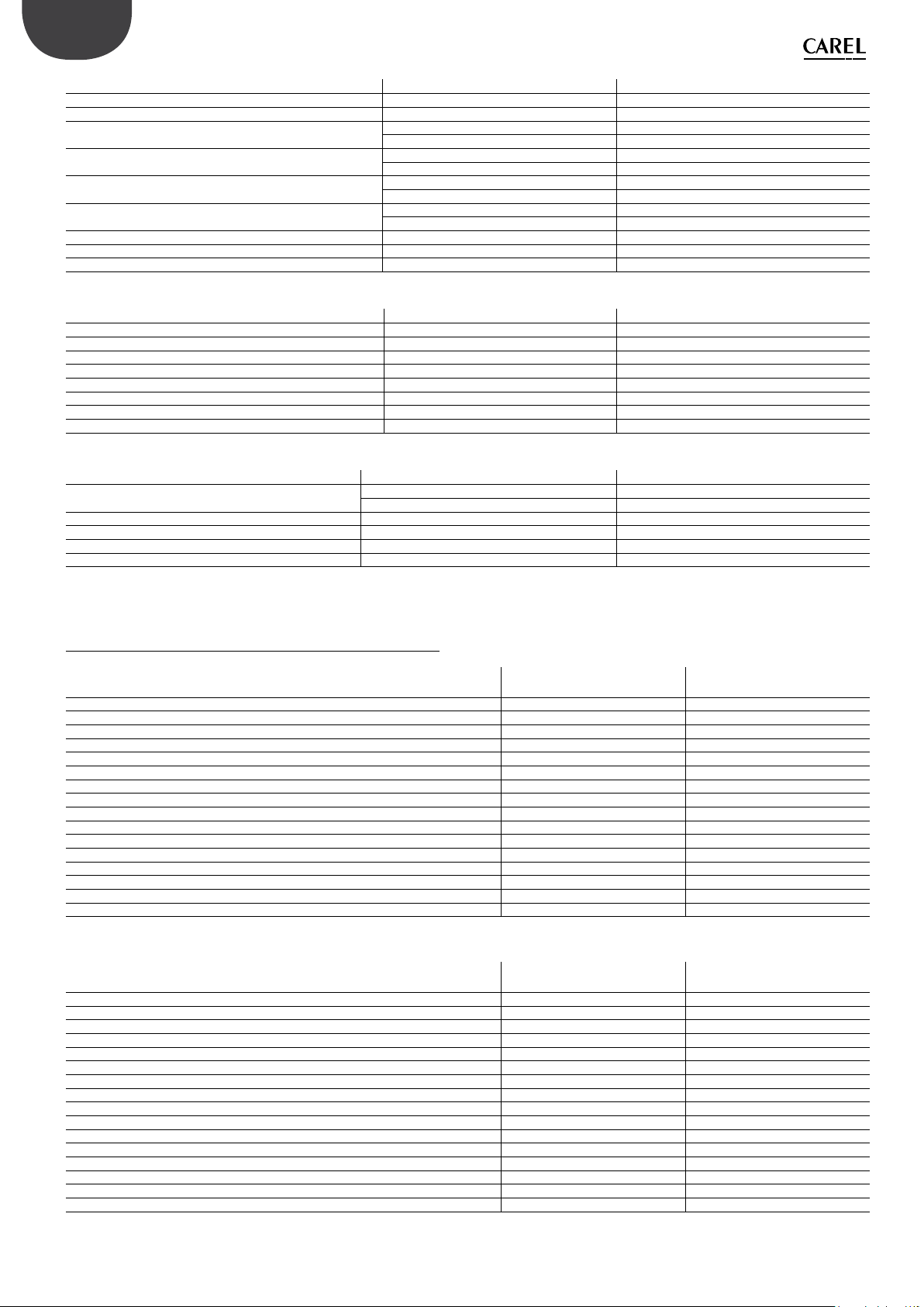
ENG
ELECTRICAL SPECIFICATIONS UA050DU*01 UA090DU*01
Power supply 120 Vac 60 Hz single-phase 120 Vac 60 Hz single-phase
Cabinet power cable AWG 14 AWG 12
Power (cabinet only, without blowers) 0.28 kW (single-zone) 0.47 kW (single-zone)
0.38 kW (two zones) 0.57 kW (two zones)
Current (cabinet only, without blowers) 5.0 A (single-zone) 8.0 A (single-zone)
5.8 A (two zones) 8.8 A (two zones)
Maximum power (cabinet with blowers) 0.74 kW (single-zone) 0.93 kW (single-zone)
0.84 kW (two zones) 1.03 kW (two zones)
Maximum current (cabinet with blowers) 10.3 A (single-zone) 13.3 A (single-zone)
11.0 A (two zones) 14.0 A (two zones)
FLA (Full Load Amperes) 0.25HP/180W 4.2 A 0.5HP/370W 7.1 A
SCCR (Short Circuit Current Rating) 5 kA 5 kA
Minimum cable size required for blower power supply AWG 14 AWG 12
WATER CIRCUIT SPECIFICATIONS UA050DU*01 UA090DU*01
Required feedwater quality demineralised demineralised
Required feedwater conductivity 5-80 µS/cm 5-80 µS/cm
Required feedwater pressure 3-8 bars 3-8 bars
Water inlet connection 3/4” GAS F 3/4” GAS F
Water drain connection 1/2” GAS F 1/2” GAS F
Water outlet connection 1/4” GAS F 1/4” GAS F
Water outlet pressure 70 bars 70 bars
Maximum capacity 50 l/h 90 l/h
FUNCTIONAL SPECIFICATIONS UA050DU*01 UA090DU*01
Number of probes allowed (temperature and/or humidity) 1 (single-zone) + limit 1 (single-zone) + limit
2 (two-zone) + limit 2 (two-zone) + limit
External signal or type of probes 0-10 V, 4-20 mA, 0-1 V, 2-10 V, 0-20 mA, NTC probe 0-10 V, 4-20 mA, 0-1 V, 2-10 V, 0-20 mA, NTC probe
Multi-probe available available
Webserver available available
Serial communication (via Ethernet and/or via RS485) Modbus, BACnet Modbus, BACnet
Tab. 12.f
Tab. 12.g
Tab. 12.h
12.3.3 CE version blower datasheet
Single blower units (for wall-mounting) DLA02DF*00 DLA04DF*00
Dimensions 640 x 200 x 180 mm 940 x 200 x 180 mm
Weight 4.5 kg 5.6 kg
Packaged dimensions 755 x 235 x 295 mm 1050 x 235 x 295 mm
Packaged weight 5.7 kg 7.4 kg
Delivery and storage temperature -10/50°C 0-90% -10/50°C 0-90%
Operating temperature 2/40°C 5-95% 2/40°C 5-95%
Ingress protection (IP) IP10 IP10
Conformity CE CE
Water tting M16x1.5 Male M16x1.5 Male
Water outlet M16x1.5 Male M16x1.5 Male
Number of nozzles 2 4
Flow-rate (depending on the type of nozzles) 3.0 l/h - 5.6 l/h - 8.0 l/h 6.0 l/h – 11.2 l/h – 16.0 l/h
Power supply 230 Vac 50 Hz 230 Vac 50 Hz
Fan total air ow-rate 300 m3/h 600 m3/h
Blower connection cable AWG 14 AWG 14
Maximum number of blower units (connected to one cabinet) 12 6
Double blower units (for mounting in centre of corridor) CE version DLA04DB*00 DLA08DB*00
Dimensions 640 x 200 x 400 mm 940 x 200 x 400 mm
Weight 9.2 kg 15.5 kg
Packaged dimensions 755 x 470 x 295 mm 1050 x 470 x 295 mm
Packaged weight 11.4 kg 18.0 kg
Delivery and storage temperature -10/50°C 0-90% -10/50°C 0-90%
Operating temperature 2/40°C 5-95% 2/40°C 5-95%
Ingress protection (IP) IP10 IP10
Conformity CE CE
Water tting M16x1.5 Female M16x1.5 Female
Water outlet M16x1.5 Female M16x1.5 Female
Number of nozzles 4 8
Flow-rate (depending on the type of nozzles) 6.0 l/h – 11.2 l/h – 16.0 l/h 12.0 l/h – 22.4 l/h – 32 l/h
Power supply 230 Vac 50 Hz 230 Vac 50 Hz
Fan total air ow-rate 600 m3/h 1,200 m3/h
Blower connection cable AWG 14 AWG 14
Maximum number of blower units (connected to one cabinet) 6 3
Tab. 12.i
Tab. 12.j
"humiFog direct" +0300073EN rel. 1.2 - 02.05.2019
44

12.3.4 UL version blower datasheet
Single blower units (for wall-mounting) UL version DLA02UF*00 DLA04UF*00
Dimensions 640 x 200 x 180 mm 940 x 200 x 180 mm
Weight 4.5 kg 5.6 kg
Packaged dimensions 755 x 235 x 295 mm 1050 x 235 x 295 mm
Packaged weight 5.7 kg 7.4 kg
Delivery and storage temperature -10/50°C 0-90% -10/50°C 0-90%
Operating temperature 2/40°C 5-95% 2/40°C 5-95%
Ingress protection (IP) IP10 IP10
Conformity UL UL
Water tting M16x1.5 Male M16x1.5 Male
Water outlet M16x1.5 Male M16x1.5 Male
Number of nozzles 2 4
Flow-rate (depending on the type of nozzles) 3.0 l/h - 5.6 l/h - 8.0 l/h 6.0 l/h – 11.2 l/h – 16.0 l/h
Power supply 120 Vac 60 Hz 120 Vac 60 Hz
Fan total air ow-rate 360 mc/h 720 mc/h
Blower connection cable AWG 14 with UA050% AWG 14 with UA050%
AWG 12 with UA090% AWG 12 with UA090%
Maximum number of blower units (connected to one cabinet) 12 6
Double blower units (for mounting in centre of corridor) UL version DLA04UB*00 DLA08UB*00
Dimensions 640 x 200 x 400 mm 940 x 200 x 400 mm
Weight 9.2 kg 15.5 kg
Packaged dimensions 755 x 470 x 295 mm 1050 x 470 x 295 mm
Packaged weight 11.4 kg 18.0 kg
Delivery and storage temperature -10/50°C 0-90% -10/50°C 0-90%
Operating temperature 2/40°C 5-95% 2/40°C 5-95%
Ingress protection (IP) IP10 IP10
Conformity UL UL
Water tting M16x1.5 Female M16x1.5 Female
Water outlet M16x1.5 Female M16x1.5 Female
Number of nozzles 4 8
Flow-rate (depending on the type of nozzles) 6.0 l/h – 11.2 l/h – 16.0 l/h 12.0 l/h – 22.4 l/h – 32 l/h
Power supply 120 Vac 60 Hz 120 Vac 60 Hz
Fan total air ow-rate 720 m3/h 1,440 m3/h
Blower connection cable AWG 14 with UA050% AWG 14 with UA050%
AWG 12 with UA090% AWG 12 with UA090%
Maximum number of blower units (connected to one cabinet) 6 3
ENG
Tab. 12.k
Tab. 12.l
45
"humiFog direct" +0300073EN rel. 1.2 - 02.05.2019

ENG
Note
"humiFog direct" +0300073EN rel. 1.2 - 02.05.2019
46


CAREL INDUSTRIES - Headquarters
Via dell’Industria, 11 - 35020 Brugine - Padova (Italy)
Tel. (+39) 049.9716611 - Fax (+39) 049.9716600
e-mail: carel@carel.com - www.carel.com
Agenzia / Agency:
"humiFog direct" +0300073EN rel. 1.2 - 02.05.2019
 Loading...