

Page 1
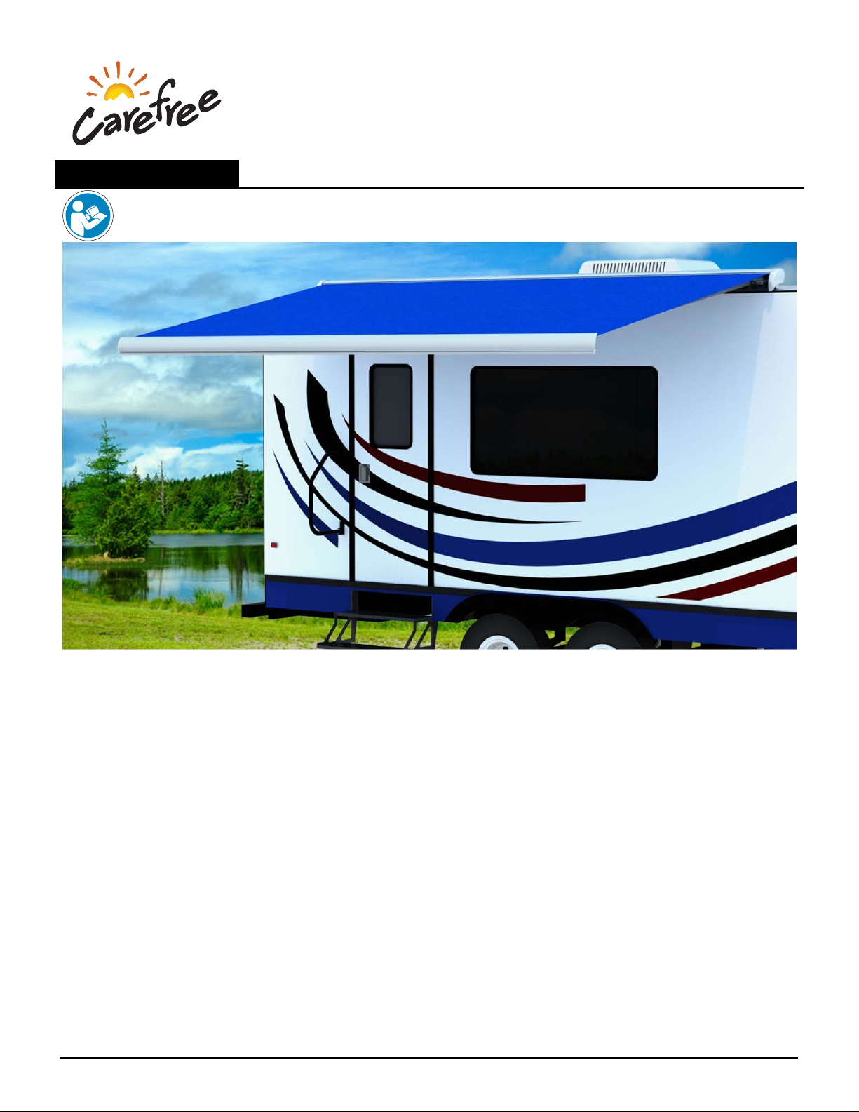
I
NSTALLATION MANUAL
F
REESTYLE EVOLUTION
12V M
RV
Read this manual before installing or using this product. Failure to follow the instructions
and safety precautions in this manual can result in personal injury and/or cause the
product to not operate properly.
OTORIZED ROOF MOUNTED BOX AWNING
T
ABLE OF CONTENTS
Product Overview .......................................................................................................................... 4
Component Checklist.............................................................................................................................. 5
Freestyle RM Bracket Kits ...................................................................................................................... 5
Installation ..................................................................................................................................... 7
Bracket Installation ................................................................................................................................. 7
Mounting the Awning .............................................................................................................................. 7
Jumping the Motor (with BT12) ...................................................................................................... 7
BT12 System Installation .............................................................................................................. 8
BT12 Control Module Installation ............................................................................................................ 9
Awning Switch Installation .................................................................................................................... 10
Awning Lights Switch Installation .......................................................................................................... 10
Wiring Diagram ..................................................................................................................................... 11
Setting the System into Pairing Mode ................................................................................................... 13
Pitch Adjustment ......................................................................................................................... 14
Adjusting the Extend Limit ......................................................................................................... 14
Manual Override .......................................................................................................................... 14
070036-001r1 Printed in USA June, 2019
Page 2

FREESTYLE EVOLUTION AWNING Installation Manual Carefree of Colorado
NOTICES AND DISCLAIMERS
TRADEMARKS
The Bluetooth
Use of such marks by Carefree of Colorado is under license.
Other trademarks and trade names are those of their respective owners.
STATEMENTS OF COMPLIANCE
● BT12 Control Module ● BT Motion Sensor ● BT Remote
FCC and IC identification numbers are located on the exterior surfaces of the individual components.
®
word mark and logos are registered trademarks owned by the Bluetooth SIG, Inc.
FCC C
These devices comply with Part 15 of the FCC rules. Operation is subject to the following two
conditions: (1) These devices may not cause harmful interference and, (2) These devices must accept
any
NOTE: This equipment has been tested and found to comply with the limits for a Class B digital device, pursuant
to part 15 of the FCC rules. These limits are designed to provide reasonable protection against harmful
interference in a residential installation. This equipment generates, uses and can radiate radio frequency energy
and, if not installed and used in accordance with the instructions, may cause harmful interference to radio
communications. However, there is no guarantee that interference will not occur in a particular installation. If this
equipment does cause harmful interference to radio or television reception, which can be determined by turning
the equipment off and on, the user is encouraged to try to correct the interference by one or more of the following
measures:
Reorient or relocate the receiving antenna.
Increase the separation between the equipment and receiver.
Connect the equipment into an outlet on a circuit different from that to which the receiver is connected.
Consult the dealer or an experienced radio/TV technician for help.
Any changes or modifications not expressly approved by the party responsible for compliance could void
the user’s authority to operate the equipment.
IC C
These devices comply with Industry Canada license-exempt RSS standard(s). Operation is subject to the
following two
accept any
Ces appareils sont conformes aux normes RSS exonérées de licence d'Industrie Canada. L'opération est
soumise aux deux conditions suivantes: (1) Ces appareils ne doivent pas causer d'interférences nuisibles et, (2)
Ces appareils doivent accepter toute interférence reçue, y compris les interférences pouvant entraîner un
fonctionnement indésirable.
OMPLIANCE
interference received, including interference that may cause undesired operation.
OMPLIANCE
conditions: (1) These devices may not cause harmful interference and, (2) These devices must
interference received, including interference that may cause undesired operation.
FCC/IC R
● BT12 Control Module ● BT Motion Sensor
This equipment complies with FCC and IC radiation exposure limits for an uncontrolled environment. The
minimum distance between the radiator and people is designed to be 20cm when installed and operated.
Cet équipement est conforme aux limites d'exposition aux radiations FCC et IC pour un environnement non
contrôlé. La distance minimale entre le radiateur et les personnes est de 20cm lorsqu'installé et utilisé.
● BT12 Remote
This equipment complies with FCC and IC radiation exposure limits for an uncontrolled environment. The
minimum distance between the radiator and people is designed to be 5mm when operated.
Cet équipement est conforme aux limites d'exposition aux radiations FCC et IC pour un environnement non
contrôlé. La distance minimale entre le radiateur et les personnes est de 5mm (à l'exclusion des extrémités:
mains, poignets, pieds et chevilles) lors de l'utilisation.
2 070036-001r1
ADIATION EXPOSURE STATEMENT
Page 3
Carefree of Colorado Installation Manual F
D
ISCLAIMERS
The BT12 Wireless Awning Control System and the Carefree Connects Mobile App are products of
Carefree of Colorado, located in Broomfield, Colorado, USA. The
this document is considered proprietary to Carefree of Colorado.
that the information presented in the document is accurate and
Colorado assumes no liability for errors or for any damages that result from
The information contained in this manual pertains to the current components and software listed on the title
page. Carefree of
procedures, described in this
information contained in or disclosed in
Every effort has been made to ensure
complete. However, Carefree of
Colorado reserves the right to cancel, change, alter or add any parts and
manual, without prior notice.
REESTYLE EVOLUTION AWNING
the use of this document.
Carefree of Colorado agrees to allow the reproduction of this document for use with Carefree of Colorado
products only. Any other reproduction or translation of this document in whole or part is strictly prohibited
without prior written approval from Carefree of Colorado.
S
ERVICE AND SUPPORT
S
AFETY INFORMATION
This is the safety alert symbol. It is used to alert individuals to potential
WARNING
CAUTION
personal injury hazards. Obey all safety messages that follow this symbol to
avoid possible personal injury or death.
Indicates a hazardous situation, which if not avoided, could result in death or
serious bodily injury.
Indicates a hazardous situation, which if not avoided, may result in minor or
moderate bodily injury.
www.carefreeofcolorado.com
www.carefreeofcolorado.com/carefreeconnects
[email protected]
Carefree of Colorado
2145 W. 6
Broomfield, CO
80020
th
Ave.
NOTICE
Indicates a situation that may result in equipment-related damage.
General Safety:
WARNING
(DIDP), Vinyl Chloride and Formaldehyde, which are known to the state of California to cause
cancer or birth defects or other reproductive harm. For more information visit
www.P65warnings.ca.gov
working on or around the electrical system.
holding heavy objects.
NOTICE
aluminum can be "stripped out" and lose the ability to grip and hold.
Carefree of Colorado www.carefreeofcolorado.com a Scott Fetzer company
070036-001r1 3
This product can expose you to chemicals including Di-isodecyl phthalate
WARNING
WARNING
CAUTION
When using fasteners, do not over tighten. Soft materials such as fiberglass and
Shock Hazard. Always disconnect battery or power source before
Always wear appropriate safety equipment (i.e. goggles).
Always use appropriate lifting devices and/or helpers when lifting or
Page 4
FREESTYLE EVOLUTION AWNING Installation Manual Carefree of Colorado
PRODUCT OVERVIEW
The Freestyle Evolution Awning is a state of the art lateral arm awning. When retracted, the housing
provides protection against the elements while the streamlined styling blends in with the vehicle
appearance. The full tension canopy fabric allows the awning to be partially or fully extended for best
shade coverage.
Each unit is equipped with lateral support arms. No vertical arms interfere with coach sidewalls, custom
graphics or equipment that may be mounted on the sidewalls.
Freestyle Awning Specifications:
Fully retractable and self-storing;
The sealed awning motor operates on standard 12VDC (range 10VDC to 14VDC);
Case and frame are constructed of high-strength aluminum extrusions, protected with a polyester paint finish;
BT12 Wireless Awning Control System is standard.
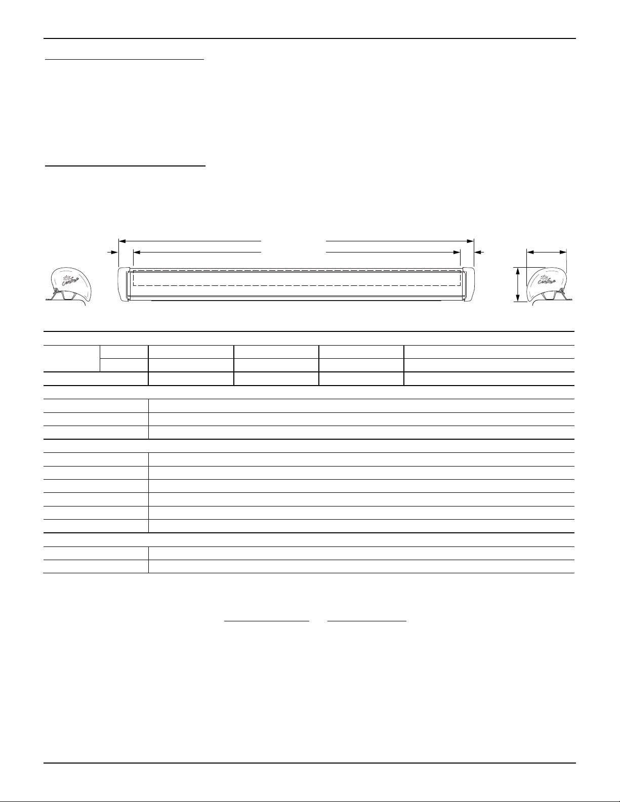
2.5"
[6.4cm]
Awning Length
Fabric Width
2.5"
[6.4cm]
6"
[15.4cm]
7"
[18cm]
ragm001
NOTE: Dimensions shown are approximate. Dimensions may vary based on specific installations.
PECIFICATIONS
S
Lengths:
Extension:
centimeters
inches
200 - 241 244 - 254 257 - 297 300 - 500
79 - 95 96 – 100 101 - 117 118 - 197
152cm (60") 180cm (72") 200cm (80") 250cm (98")
LEADING EDGE POSITION ACTUATION AND CONTROL
Power:
Position Control:
Controller:
Lateral Arm Spring
12V Motorized
BT12 Wireless Awning Control System
Minimum Tension
Open
MOTOR SPECIFICATIONS
Motor Type:
Power:
Tubular
12VDC Minimum: 10VDC Output: 30 Watts
Nominal Current: 2.5Amps Max Current: 14Amps (stall @ min voltage)
Power Source:
Torque
Speed
Motor and controls are routed and hardwired into the vehicle’s 12V system
Continuous: 6Nm/4.5 ft-lbs.
24 rpm
COLORS AVAILABLE
Case
Fabric:1
Satin, White or Black
Vinyl or Woven Acrylic
Special Note: Dimensions are provided in centimeters. Conversion formulas are provided below;
Inches =
Centimeters
2.54 25.4
Millimeters
=
Centimeters = Inches x 2.54 Millimeters = Inches x 25.4
4 070036-001r1
Page 5
Carefree of Colorado Installation Manual FREESTYLE EVOLUTION AWNING
COMPONENT CHECKLIST
1
ON
RE
T
3
RACT
O
F
F
EXTEN
Awnin
D
g
Co
nt
ro
l
ON
RETR
4
ACT
OFF
E
X
TEND
Awn
ing C
o
ntrol
5
2
3a 3d3c3b
ragm002
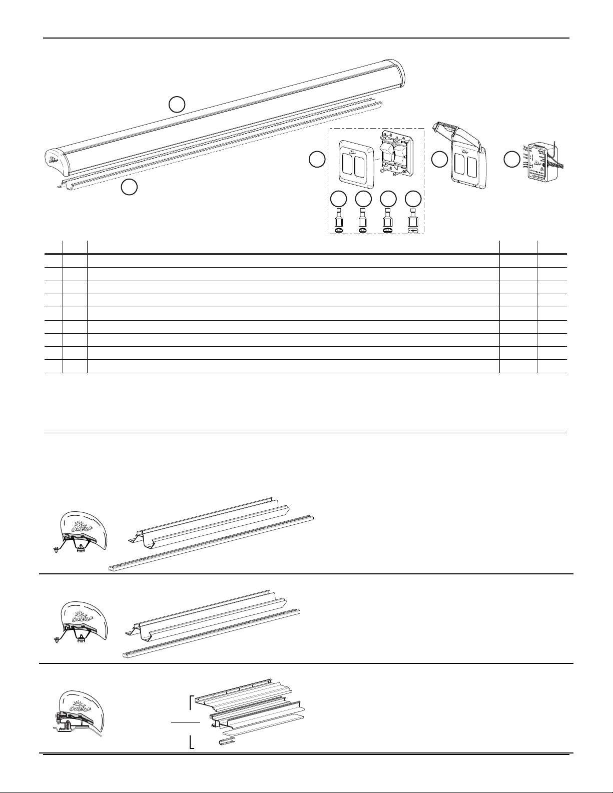
TEM DESCRIPTION QTY NOTE
I
NOTES: 1. Specific awning configuration is specified at time of order, including awning length, fabric, color etc. check
Awning Assembly, Complete 1
1
Mounting Bracket Ordered Separately, Refer to “Freestyle RM Bracket Kits”
2
Switch Kit 1
3
3a
3b
3c
3d
4
5
Terminal, Female, .187 18-22 awg 3
Terminal, Female, .187 14-16 awg 2
Terminal, Female, .25 14-16 awg 1
Terminal, Male, .25 14-16 awg 1
Covered Bezel, 2 Switch 1 2
BT12 Control Module 1 3
awning assembly against original purchase order.
2. The covered bezel (item 4) is optional and ordered separately. Refer to page 8 for information about
NFPA 1192 RV Standard, Section 6.4.9 (Switch Installation Requirements).
3. The BT Motion Sensor is factory installed in the lead rail on the motor side.
FREESTYLE RM BRACKET KITS
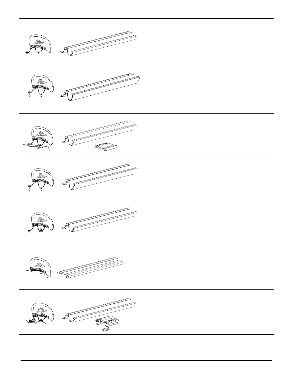
Bracket kits are ordered separately. Several types are available based on the application installation.
Bracket mounting instructions are separate instructions that supplement this manual.
BS0012 Sprinter
(x3)
28"
42"
(x3)
BS0012a
BS0013 Sprinter
(x2)
28"
36"
(x2)
BS0013a
BS0014 Dodge ProMaster; Fiat Ducato
-4 (x4)
-5 (x5)
BS0014a
070036-001r1 5
4.5m & 5m
Mill Finish
Bracket and Awning Hardware included
Instruction Supplement: 052570-012
4m and less
Mill Finish
Bracket and Awning Hardware included
Instruction Supplement: 052570-013
(-4) 4 Brackets 3.5m
(-5) 5 Brackets 4m
Mill Finish
Bracket and Awning Hardware included
Instruction Supplement: 052570-014
Page 6
FREESTYLE EVOLUTION AWNING Installation Manual Carefree of Colorado
BS0016 Flat Roof
(-3) 3 Brackets 4m
(-4) 4 Brackets 4.5m & 5m
28"
Mill Finish
BS0016a
Bracket and Awning Hardware included
Instruction Supplement: 052570-016
BS0017 Sprinter – No Rail
(-28-2) 2 Brackets up to 4m
Mill Finish
Bracket and Awning Hardware included
Instruction Supplement: 052570-017
F
ULL LENGTH BRACKETS
28"
BS0017a
BS0015 Ford Transit
(-118-XX) Full Length 3m
Full Length
(-138-ML) Full Length 3.5m
(-157-XX) Full Length 4m
Mill (ML) or Black (JV) Finish
Bracket and Awning Hardware included
BS0015a
Instruction Supplement: 052570-015
BS0018 Sprinter – No Rail
(-118-XX) Full Length 3m
(-157-XX) Full Length 4m
Full Length
(-177-XX) Full Length 4.5m
Mill (ML) or Black (JV) Finish
Bracket and Awning Hardware included
BS0018a
Instruction Supplement: 052570-018
BS0019 Sprinter used w/ OEM Rail or Flat Roof
(-118-XX) Full Length 3m
(-157-XX) Full Length 4m
Full Length
(-197-XX) Full Length 5m
Mill (ML) or Black (JV) Finish
Bracket and Awning Hardware included
BS0019a
Instruction Supplement: 052570-019
BS0021 Low Profile RM Mounting Bracket Kit
(-157-ML) Full Length 4m
(-177-XX) Full Length 4.5m
Full Length
BS0021a
Mill (ML) or Black (JV) Finish
Bracket and Awning Hardware included
Instruction Supplement: 052570-021
BS0023 Dodge ProMaster
(-157-XX) Full Length 4m
Full Length
Mill (ML) or Black (JV) Finish
Bracket and Awning Hardware included
BS0023a
Instruction Supplement: 052570-023
6 070036-001r1
Page 7
Carefree of Colorado Installation Manual FREESTYLE EVOLUTION AWNING
INSTALLATION
BRACKET INSTALLATION
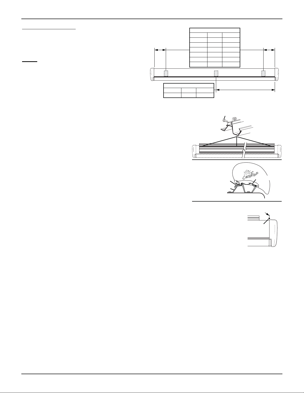
Install the mounting brackets according to the
supplement instructions for the bracket kit.
OTE: Install the brackets according to the
N
bracket design. To correctly support the awning,
the brackets must be positioned below the arm
case knuckles. After the brackets are installed,
go to "Mounting the Awning".
MOUNTING THE AWNING
These steps apply to all bracket configurations.
1. If not previously done, in the rear track of the mounting plate(s),
start three (3) M6 x 20 screws and square nuts through the
holes. Do not tighten at this time.
NOTE: Locate 1 screw and nut at each end of the awning, the third
screw and nut should be located near the center of the awning.
2. Lift and set the awning into the hooks of the mounting brackets.
Pull the case forward to engage the brackets fully.
3. Horizontally center the awning on the brackets.
4. Tighten the rear screws. Torque to 10 ft-lbs [13.6 nm].
5. The motor and switch wires come out of the back of motor endcap.
Drill a 5/16" [8mm] hole into the vehicle in the area shown.
Edge of
Case
Center Knuckle
4.5m 60.0" 152cm
5.0m 69.75" 177cm
Outside Connector
2.44m 5.0" 13cm
2.57m 5.0" 13cm
3.0m 3.25" 8cm
3.5m 13.25" 33.5cm
4.0m 13.25" 13.5cm
4.5m 4.0" 10cm
5.0m 14.0" 35cm
M6 Screw & Square Nut
(3 per awning)
Tighten Screw to
10 ft-lbs.
[13.6nm]
(3 plcs)
Mounting Bracket
Edge of
Case
ragm004
Awning Frame
NOTE: Locate the hole to avoid interior framing, cabinets and
electrical components.
Align Hole with Edge of Endcap
and Slightly Behind Awning
Ensure that the motor wires are accessible after routing.
Ø 5/16" [8mm] Hole
thru Roof
ragm003
Jumping the Motor (with BT12)
This method is used if the BT12 Wireless Awning Control System is to be used.
1. Temporarily connect the ends of the motor wires to a 12V-14V source (i.e. drill battery). If the awning
does not begin to move, reverse the leads.
2. Remove the battery after the awning is open.
070036-001r1 7
Page 8
F
REESTYLE EVOLUTION AWNING
Installation Manual Carefree of Colorado
BT12
NOTICE
mounted as follows:
SYSTEM INSTALLATION
WARNING
working on or around the electrical system.
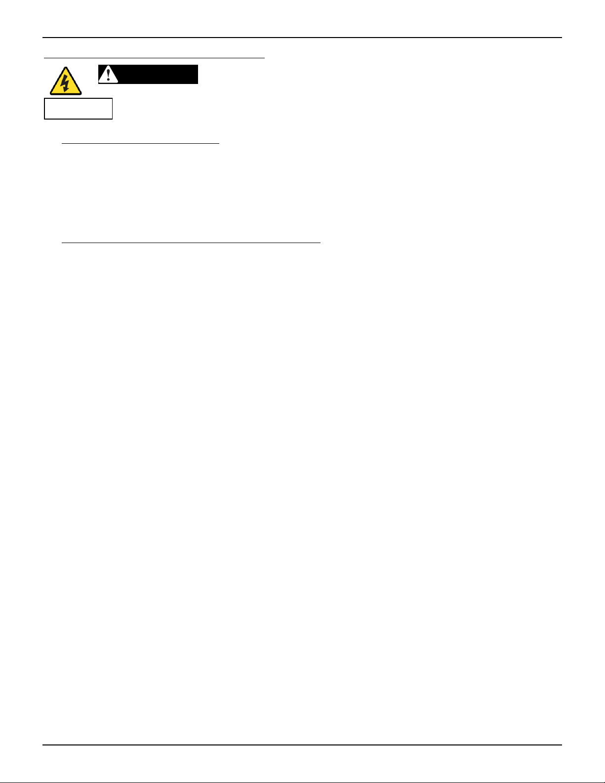
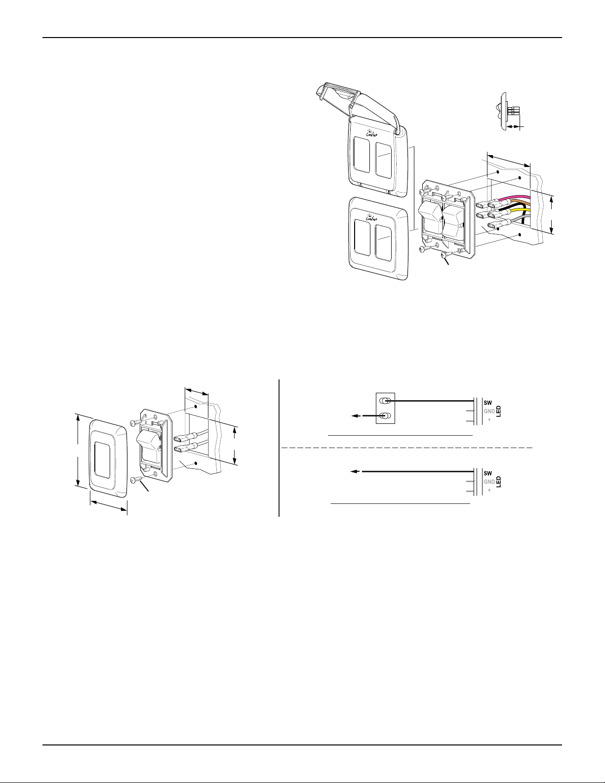
To comply with 2018 NFPA 1192 RV Standard, Section 6.4.7, switches must be
For travel trailers and 5
Shock Hazard. Always disconnect battery or power source before
th
wheels:
a) Installed in a dedicated switch cabinet with a latching door; or,
b) Installed with the optional covered bezel available from Carefree; or,
c) Installed in a cabinet with a latching door where the switch is protected and
CANNOT
be activated by
any items or cargo that may move or shift during transit; or,
d) Installed with an interrupt circuit that disables awning extension when the vehicle is in motion (i.e. a relay
tied into the parking brake or ignition that disconnects the
BROWN
extend wire).
For motorized coaches (Class A, Class B or Class C):
a) Installed with an interrupt circuit connected to the “IGN LOCK” (green wire).
The BT12 module provides an ignition lockout option. When the “IGN LOCK” (green wire) is connected to
the vehicle PCM or other switched source the following parameters are set:
i) If Open = Awning Active
ii) If tied to GND = RTL (Retract Then Lock) – Awning retracts, extend command disabled
iii) If tied to +12Vdc = Standard – Extend command disabled
To Start:
1. Determine the location for the awning switches, awning lights switch and BT12 control module.
NOTE: The BT12 control module leads are 6" in length. If the distance between the module and the
switches is greater than 6", the installer must furnish splice wires for the extra distance. Use
appropriate size wire gauges. Use appropriate sized butt splices to secure connections.
2. Route the motor cable and LED harness to the location of the module.
8 070036-001r1
Page 9
Carefree of Colorado Installation Manual FREESTYLE EVOLUTION AWNING
BT12 CONTROL MODULE INSTALLATION
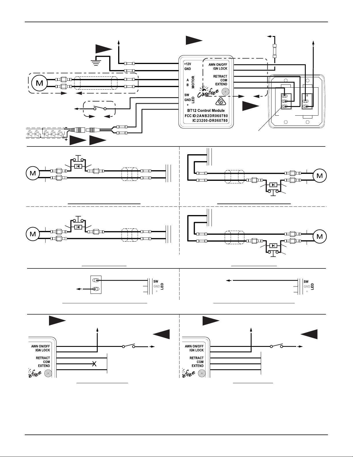
(Refer to the wiring diagram on page 11.)
NOTICE Do not mount the unit near heat producing elements such as LP appliances or engine
exhaust components.
NOTICE For best reception, do not mount the unit near or on a metal surface.
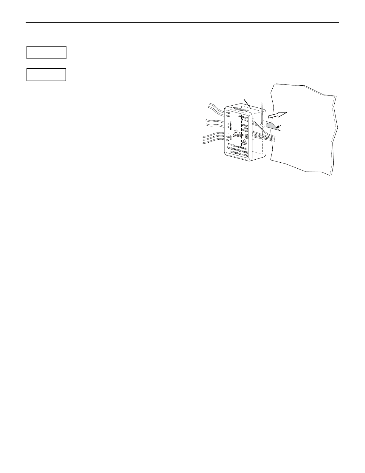
1. Clean the mounting surface. The surface must be flat and
clean for the mounting tape to properly adhere.
2. Remove the release paper from the tape on the back of the
module and firmly press the module onto the mounting
surface.
NOTE: The module may be oriented for best fit with
access to the wire leads.
3. Attach the motor wires (refer to diagram for corresponding
wire colors) to the module leads for the motor using 1416awg butt splices.
Mounting
Tape
Remove
Release Paper
4. Run a minimum 14 awg wire to chassis ground.
Suitable ground would be the vehicle chassis or
conductive structure connected to the chassis. Splice
BT003
the wire to the module GND lead with a 14-16awg butt splice.
5. Run a minimum 14 awg wire from the power distribution panel (auxiliary battery circuit) or equivalent. The
circuit should be protected by a 15-amp fuse. Splice the wire to the module +12V lead with a 14-16awg
butt splice.
NOTE: If the wire run is 30 feet or longer for +12Vdc and/or GND, use 12awg wire to prevent voltage
drop. Use the appropriate butt splices for the wire size.
6. Splice the Black wire from the LED Harness to the module LED GND lead (Black) with a 18-22awg butt splice.
7. Route the module LED + lead (RED) to the awning lights switch location. Use 20awg wire and 18-22awg butt
splice to extend the lead as necessary.
8. Route the module IGN LOCK lead (Green) to the vehicle PCM or other switch source (used for ignition lockout).
9. Route the remaining wires (Violet, Gray, Yellow and Brown) to the location for the awning control switches. Use
20awg wires and 18-22awg butt splices to extend the leads as necessary.
070036-001r1 9
Page 10
FREESTYLE EVOLUTION AWNING Installation Manual Carefree of Colorado
AWNING SWITCH INSTALLATION
(Refer to the wiring diagram on page 11.)
1. At the switch location cut a 2.32" x 1.5" hole.
2. From the module, terminate the three (3) 20awg
R
ETRACT
Optional
Covered Bezel
1"
2.32"
wires (Brown, Yellow and Gray) with .187, 18-20
awg female terminals. Attach to the
E
XTEND/RETRACT switch as shown in the wiring
diagram.
ON
3. From the module, terminate the Violet wire with a
.187, 18-20 awg female terminal. Attach to the
O
F
F
E
X
T
E
N
A
D
wnin
g C
ontr
ol
ON/OFF switch.
4. Run a minimum 14 awg wire to +12VDC. Terminate
the wire with .187, 14-16 awg female terminal and
ON
R
ETRACT
1.5"
connect to the second terminal of the ON/OFF switch.
NOTE: If the wire run is 30 feet or longer, use
12awg wire to prevent voltage drop. Use the
appropriate wire terminals for the wire size.
OFF
EXTEND
A
wn
i
n
g Control
#6 x 1/2" Screw (x4)
BT001
5. Push the wires and switches into the hole then attach the switch frame using 4 #6 x 1/2" screws.
6. Snap the switch bezel over the switch frame.
AWNING LIGHTS SWITCH INSTALLATION
NOTE: Installers may choose to furnish the control switch or may wire directly to a multiplexing control
center.
1.13"
2.9"
White/Violet
To +12VDC
ON
1.5"
To Multiplexing
OFF
Single Pole, Single Throw Switch
White/Violet
Controller
(20awg)
(20awg)
#6 x 1/2" Screw (x2)
1.88"
Multiplexing Control Connection
BT004d
1. Determine the location of the switch.
2. At the switch location, cut a 1.13" x 1.5" hole.
3. Wire the switch as shown. Wire terminals at the switch are .187, 18-24 awg female disconnects.
4. Press the wires and switch into the mounting hole. Secure the switch using two (2) #6 x 1/2" screws.
5. Snap the switch bezel over the switch frame.
10 070036-001r1
Page 11
Carefree of Colorado Installation Manual FREESTYLE EVOLUTION AWNING
WIRING DIAGRAM
To +12VDC
LED Strip
Green
Orange
To +12VDC
1
Red
GND
F
M
F
M
A
White/Violet
White/Black
White/Red
Black
Blue
White
(16awg)
(16awg)
(16awg)
(16awg)
(20awg)
(20awg)
(20awg)
3
or other switched source
Control Module
To vehicle PCM
(18awg)
Violet
(18awg)
Green
(18awg)
Gray
(18awg)
Yellow
(18awg)
Brown
C
2
B
Black
Red
4 5
Limit Switch
Black
F
F
M
M
Red
F
M
Blue
Brown
Blue
White
A
B
MOTOR
Right Angle Gear Motor - LH Right Angle Gear Motor - RH
.187, 18-20awg Female
Spade Terminals (x5)
Blue
White
A
B
MOTOR
Blue
Brown
M
Red
Extend/
Retract
F
To +12VDC
On/Off
Rear View of
Switch Assy
Green
M
F
M
F
Orange
Black
Limit Switch
(18awg)
Red
Black
Brown
F
F
Blue
To +12VDC
3
Limit Switch
Red
M
M
F
Blue
M
Brown
White/Violet
(20awg)
Single Pole, Single Throw Switch
To vehicle PCM
or other switched source
Awning Disable
Violet
Green
Gray
Yellow
Brown
(18awg)
(18awg)
(18awg)
(18awg)
(18awg)
Switch
M1
M2
Blue
A
B
Blue
Brown
Blue
White
A
B
MOTOR
DETAIL
White
A
Motor Connect
To Multiplexing
Controller
DETAIL
B
Multiplexing Control Connection
Awning Lights Switch Options
3
6 6
+12VDC
Violet
Green
Gray
Yellow
Brown
MOTOR
M
F
Red
Tubular Motor RHTubular Motor LH
White/Violet
To vehicle PCM
or other switched source
Awning Disable
(18awg)
(18awg)
(18awg)
(18awg)
(18awg)
Switch
S1
Com
S2
Brown
M
F
M
F
Blue
Black
Limit Switch
(20awg)
+12VDC
Direct Motor Control
DETAIL
C
Multiplex Control System
Dry Connectors
BT002ragm
070036-001r1 11
Page 12
FREESTYLE EVOLUTION AWNING Installation Manual Carefree of Colorado
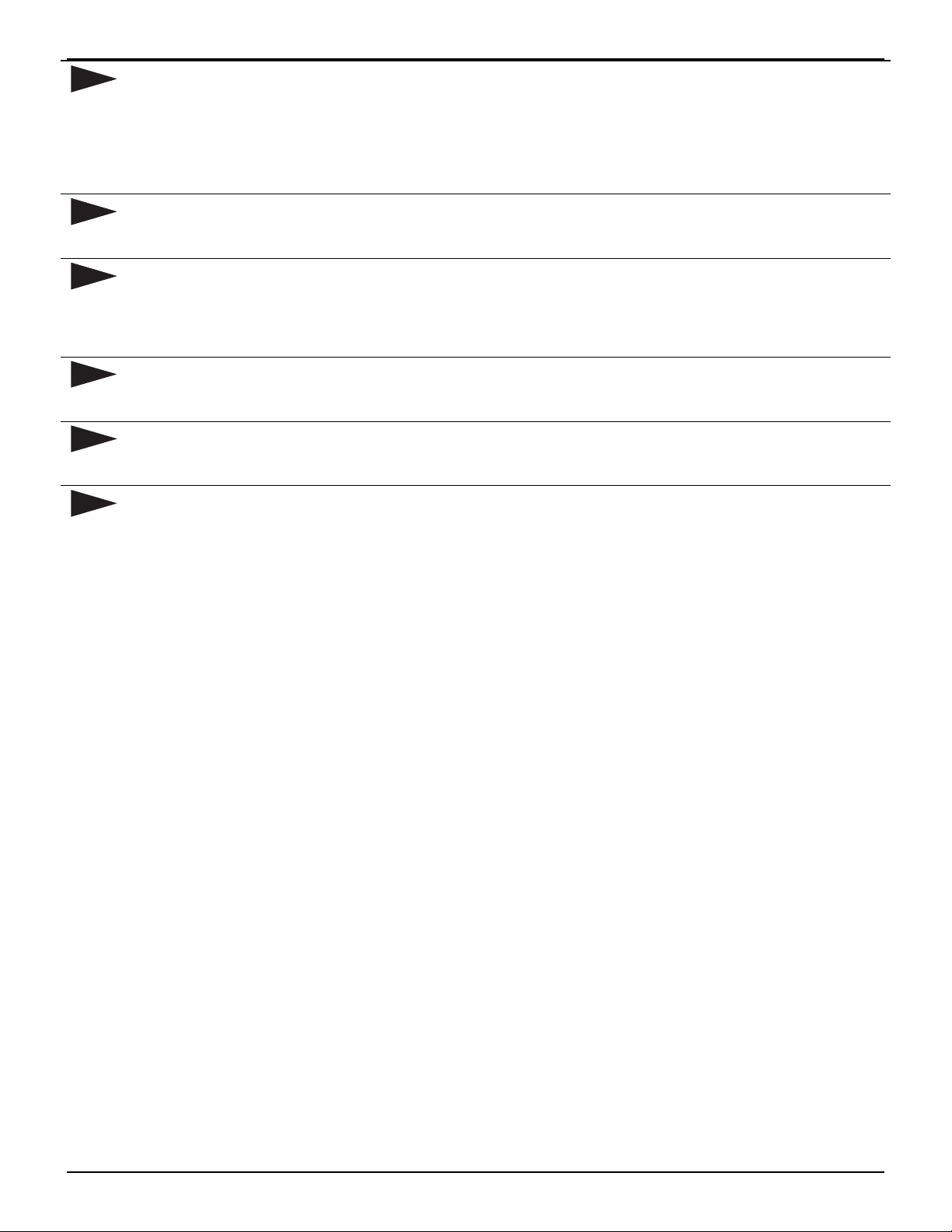
1
For GND, run a minimum 14 awg wire to chassis ground. Suitable ground would be the vehicle chassis
or conductive structure connected to the chassis.
For +12Vdc, Run a minimum 14 awg wire from the power distribution panel (auxiliary battery circuit) or
equivalent. The circuit should be protected by a 15-amp fuse.
NOTE: If the wire run is 30 feet or longer, use 12awg wire to prevent voltage drop. Use the
appropriate wire terminals for the wire size.
2
The BT12 module leads are 6" in length. If the distance between the module and the switch is
greater than 6", the installer must furnish splice wires for the extra distance. Use appropriate size
wire gauges. Use appropriate sized butt splices to secure connections.
3
4
The BT12 module provides an ignition lockout option. When the “IGN LOCK” (green wire) is
connected to the vehicle PCM or other switched source the following parameters are set:
a) If Open = Awning Active
b) If tied to GND = RTL (Retract Then Lock) – Awning retracts, extend command disabled
c) If tied to +12Vdc = Standard – Extend command disabled
The LED connection is optional to provide LED controls through the app for white LEDS only.
White LEDS can also be installed per the standard LED installation without BT12 Controls. RGB
lights must be installed per the standard RGB installation.
5
Carefree LED lights uses a 2 amp circuit draw. The BT12 limits the output current to 2 amps. If
using a different brand of high output LED’s that draws more than 2 amps, the lights will flicker
and not perform as expected.
6
The awning disable switch is a single throw; single pole switch used with OEM Multiplexing
Control Systems. Switch is furnished by installer.
12 070036-001r1
Page 13
Carefree of Colorado Installation Manual F
S
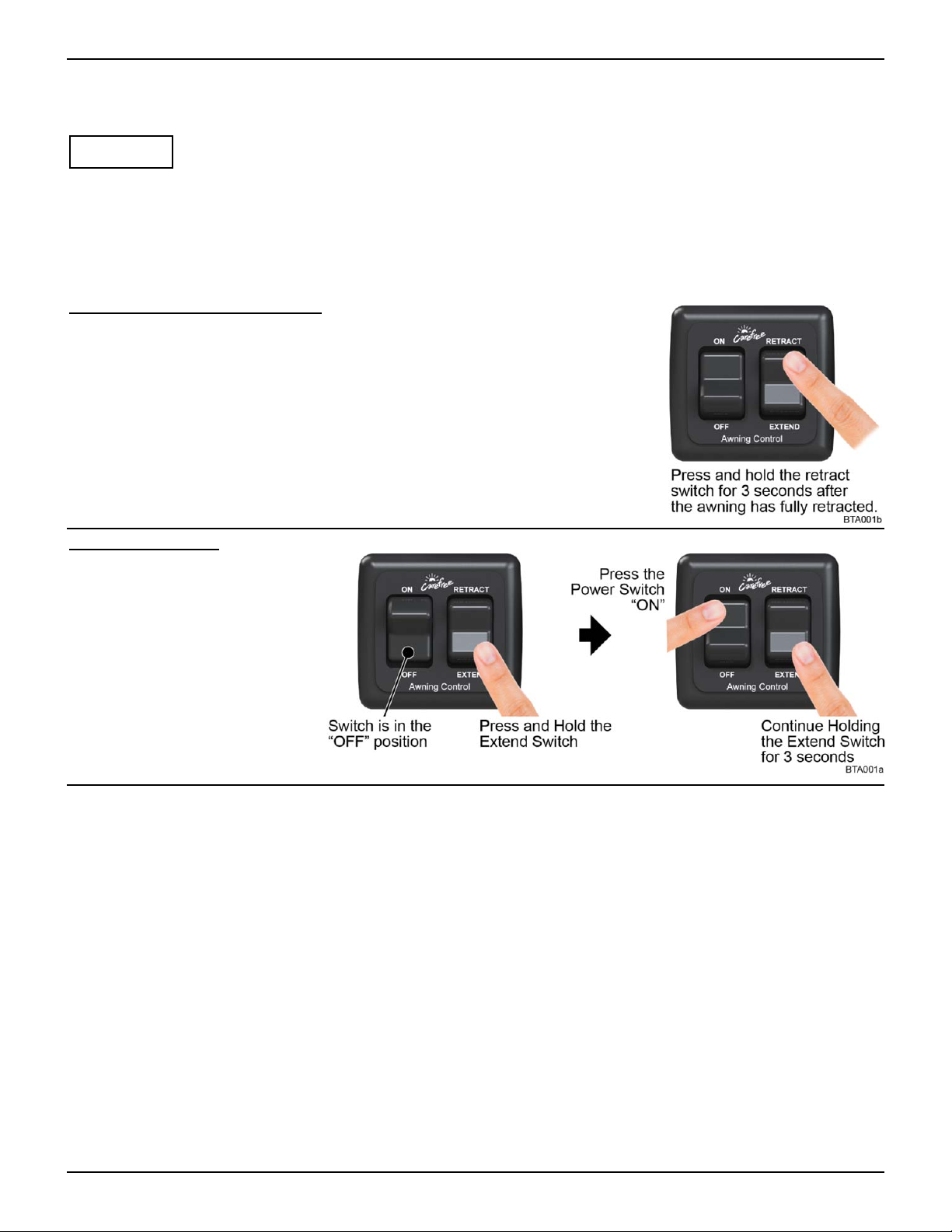
ETTING THE SYSTEM INTO PAIRING MODE
NOTE: Kits are paired at the factory for simplified installation. Separate components that are added or
used for replacements must be paired to the existing control module.
REESTYLE EVOLUTION AWNING
NOTICE
unique to each control module.
NOTE: The illustration shows the standard Carefree switches. Some OEM’s may choose to furnish their own
switches or incorporate the power and Extend/Retract controls in a multiplexing control system. The following
directions are valid for all configurations.
There are two methods to set the system into pairing mode.
Using the Awning Retract Function:
1. Turn power to the awning ON.
2. Extend the awning. Note that the awning does not have to be opened
completely.
3. Retract the awning.
4. When the awning is fully retracted, press and hold the retract switch for 3
seconds.
Using the Switches:
1. Turn the awning power
switch to OFF.
Ensure that the kits are kept together and not mixed with other kits. The pairings are
2. Press and hold the extend
switch.
3. While holding the extend
switch, turn the power
switch ON.
4. Continue to hold the extend
switch for 3 seconds, then
release.
NOTES:
The awning will remain in pairing mode for 5 minutes.
The BT12 control module will pair to the physically closest unpaired device first then go to working mode.
Repeat the pairing for each additional device (the module remembers the devices that have been paired).
Refer to the Carefree Connects Mobile App manual for setting up and pairing a smart device (such as a
smart phone or tablet).
Multiple devices can be paired to the awning up to a maximum of 8 peripheral devices.
o Only one active BT Motion Sensor can be paired to the BT12 Control Module.
o Only one active BT Remote can be paired to the BT12 Control Module.
o Multiple mobile devices (smartphone or tablet) can be paired to the BT12 Module but only 1 can be
active at a time.
070036-001r1 13
Page 14
FREESTYLE EVOLUTION AWNING Installation Manual Carefree of Colorado
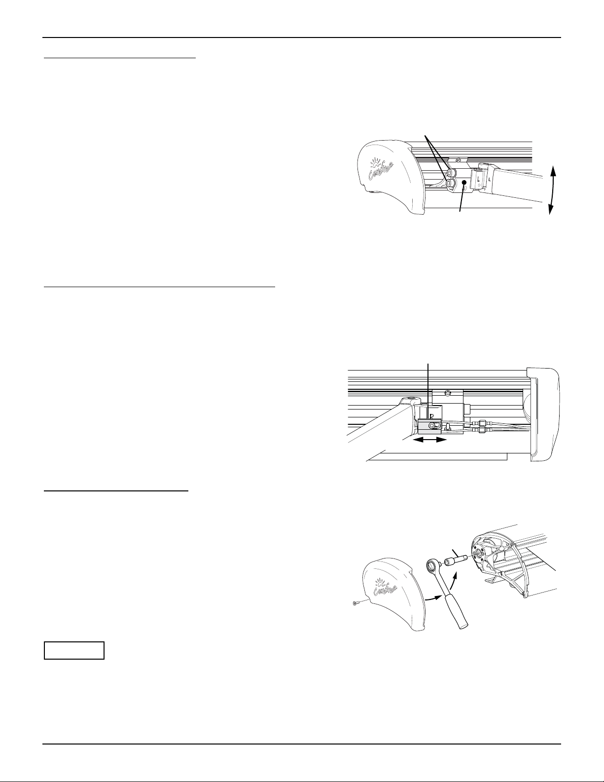
PITCH ADJUSTMENT
The awning opens and closes with a steep pitch. On low profile vans, the leading edge of the awning may
hit the top of the sliding door if the door is open while extending or retracting the awning. To prevent this,
the lower limit of the pitch can be adjusted upwards.
1. Open the awning to access the screws located on the side
of the arm case knuckles.
Loosen Screws to Adjust
Tighten to 50 ft-lbs. When Finished
2. Using an 8mm allen wrench, loosen the 2 screws on the side of
the case connector.
3. Have a second person lift the lead rail to the desired height.
4. When the pitch is set at the desired angle, tighten the screws.
Torque to 50 ft-lbs.
5. Repeat for each arm. Ensure that the lead rail is parallel
with the awning case.
Case
Knuckle
ragm005
NOTE: The lead rail is self-adjusting. No adjustment is required to the lead rail when the pitch is changed.
ADJUSTING THE EXTEND LIMIT
The extend limit switch disables the extend function when the awning is fully extended. This prevents the
awning from overextending and can be adjusted so that the canopy is tight when the awning is extended.
The switch is located on the arm knuckle closest to the motor (i.e. right knuckle for RH motor, left knuckle
for LH motor).
To adjust the extension:
1. Open the awning to access the switch.
2. Loosen the screw.
Extend Limit Switch
3. Move the switch toward the arm to decrease the
extension.
4. Move the switch away from the arm to increase the
extension.
IncreaseDecrease
ragm007
MANUAL OVERRIDE
If power to the vehicle is not available, the awning can be safely retracted using the manual override
located on the idler end of the case.
NOTE: This procedure cannot be used to extend the awning.
1. Remove the outer endcap on the idler side and save.
2. Insert a 3/8" socket drive extension and handle into the
square drive hole inside the inner end cap.
3. Turn the handle to match the direction arrows until the
awning is retracted.
4. Replace the outer cap.
NOTICE After closing the awning with the manual override, the lead rail may move out from the
case 1/4" -1/2". This is normal and the awning is secure for travel until power is restored or repairs
are completed. Do not attempt to force the lead rail in with the override, serious damage can occur
to the awning.
3/8" Socket
Drive Extension
Remove
Cover
ragm006
14 070036-001r1
 Loading...