

Page 1
UI SmartSeat iss01, 03/2013
I S S S S S SS S S S S S S SSS SS
mamamamamamamammamamamama
ma
ma
ma
rt
rtrtrt
rtrtrtrtrtrtrtrtSeSeSeSeSeSeSeSeSe
Se
SeSeSeSeSeatat
atatatatatat
at
at
ataat
i i iii i i
i
i
i i
i i
issss
sssssssssssssssssss
sssss010101010101010101001
0303030303030303030303030303/2
/2/2
/2/2/2/2/22010101010101010101010101013
33
3
3
3333
3
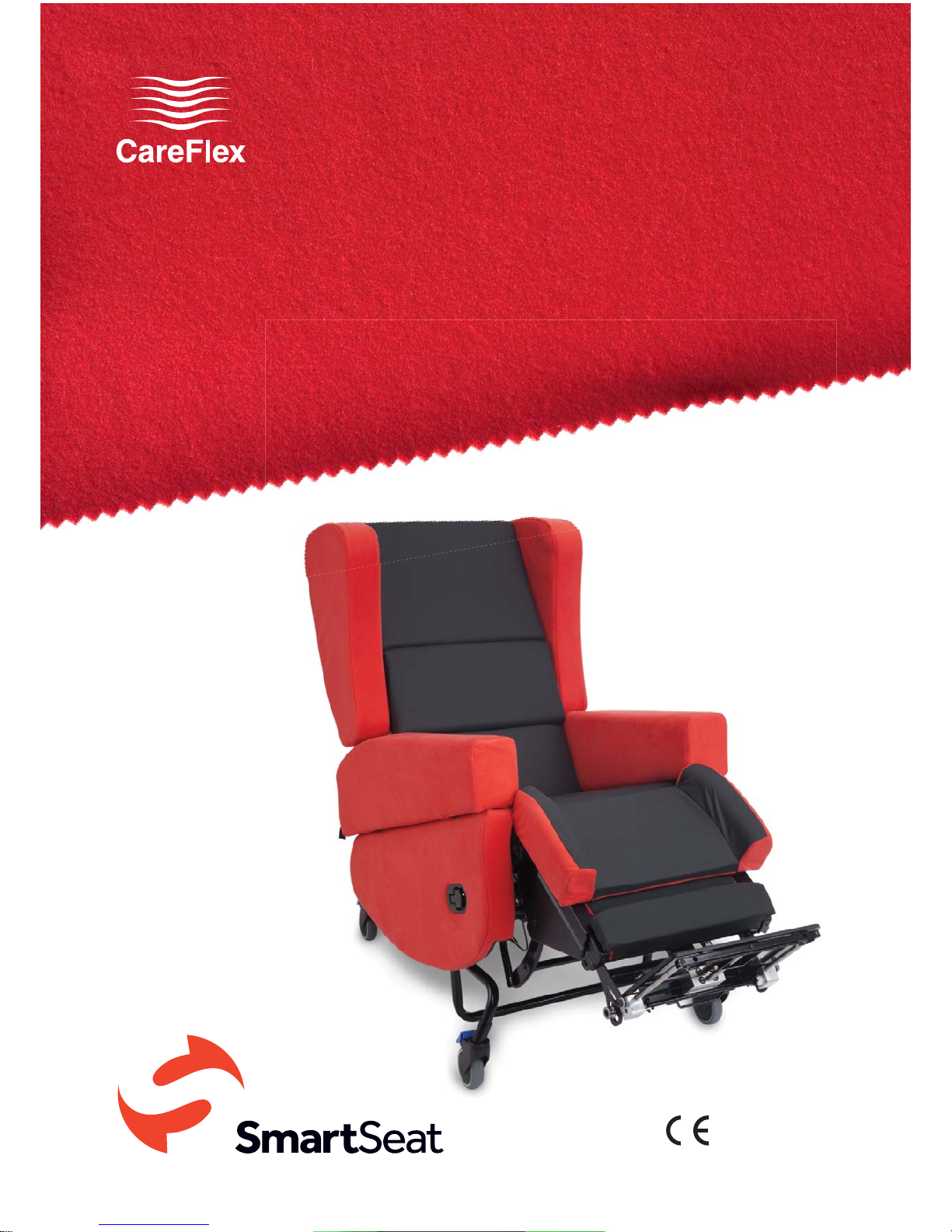
The CareFlex SmartSeat
User instructions
CareFlexibility
Class 1
Medical Device
TM
TM
Page 2

SmartSeat
®
UI SmartSeat iss01, 03/2013
TM
These are the user instructions for
the SmartSeat specialist seating
system from CareFlex. Please read
them carefully before using the
chair and keep them in a safe place
for future reference.
These instructions include details of the
performance of the chair. If the chair
should start behaving outside of its
intended performance, show signs of
damage or excessive wear, or otherwise
feel unsuitable, please take it out of
service and contact CareFlex or your
CareFlex Distributor immediately.
If you are in any doubt about the
safe operation of the SmartSeat,
contact CareFlex or your
local CareFlex distributor for
clarification and further training.
2
Page 3

UI SmartSeat iss01, 03/2013
Index
4 .................................................. Who is the SmartSeat for?
7
........................................................................................... Chair Set-up
7
............................................................................................... Seat Depth
8
................................................................................................ Seat Width
11
..........................................................................................Seat Height
12
........The SmartSeat Chair in Day to Day Use
12
......................................................................................................... Brakes
12
......................................................................................... Tilt in Space
14
...................................................................................................... Legrest
15
................................................................................................ Footplate
18
..............................................................................................................Arms
20
..................................................................................................... Options
20
.............................................................................Contoured Back
22
......................................................................................... Accessories
22
...................................................................Adjustable Laterals
24
................................................................................................. Headrest
25
..................................................................................................... Pommel
27
................................................................ Belts and Harnesses
34
.................................................................................................................Tr ay
36
............................................................ Motorised SmartSeat
38
................................................................. Care & Maintenance
40
......................................................... Dimensions & Weights
3
Page 4

SmartSeat
®
UI SmartSeat iss01, 03/2013
TM
4
Who is the SmartSeat for?
The SmartSeat chair is designed for a range of clients who require a combination
of comfort, pressure management and posture control from their seating system.
The chair has a built-in pressure management system based on CareFlex’s patented
WaterCell Technology®.
The adjustability of the chair and the range of complementary accessories mean
that the chair is suitable for clients who require specific support and positioning to
achieve a good posture. The chair can be used in single or multi-user environments.
The SmartSeat chair should be selected for clients:
• Who need to maintain a reasonable, midline posture.
• With neurological conditions which make them sensitive to discomfort or affect .
muscle tone so that support is required to combat fatigue.
• For whom seat height for transfer is critical.
• When posture, pressure and comfort are important in equal measure.
• Who require a wide range of positions for different activities through the day.
The SmartSeat chair should also be considered:
• For multi-user environments such as stroke wards.
• Where infection control is an issue.
The SmartSeat chair is all about keeping the client in a functional position which is
also comfortable and minimizes the risk of soft tissue damage. Once set up, the
support will accommodate a range of postures.
The SmartSeat chair is suitable for clients who have or are:
• Congenital conditions e.g. Cerebral Palsy
• Neurological conditions e.g. MS, MD, MND
• Lower limb amputation
• Early stage HD
• Recovering from a Stroke or have long terms effects of a stroke
• Learning difficulties
• Frail and/or elderly
Page 5

UI SmartSeat iss01, 03/2013
5
SmartSeat Unique Features
The SmartSeat chair incorporates features which allow it to be set up to
accommodate different postures and provide seating positions for a range of
activities. The key features are:
• Tilt-in-Space, which allows the client’s position to be adjusted without affecting
pelvic position.
• Legrest elevation, to raise the legs and support the lower leg with the knees at a
relaxed angle.
Pressure Relief and Support Features
CareFlex’s Unique WaterCell Technology
®
The SmartSeat chair incorporates CareFlex’s patented WaterCell Technology® in
the seat in combination with a composite visco elastic memory foam and high elastic
foam cushion. The memory foam allows the seat cushion to conform to the client’s
body shape, distributing their weight over as large a surface area as possible. The
high elastic foam prevents the memory foam bottoming out and makes the cushion
responsive to client movement. The WaterCell Technology moves with the client
to ensure that the cushion remains in contact with the client as they move and alter
their weight distribution.
These pressure relief features make the SmartSeat chair suitable for those
clients at medium to high risk of pressure damage when used as part of a
therapy programme assessed and prescribed by an appropriate Healthcare
Professional.
Back Support Options
Two back support options are available for the SmartSeat chair. The deep laterally
contoured back has kidney pads to provide simple lateral stability. These pads also
increase the contact surface between client and seat, distributing their weight over
as large a surface area as possible. The flat back has a basic lumbar curve and allows
for the use of the SmartSeat adjustable laterals accessory which provides more solid
prescriptive support to the thorax.
Page 6

SmartSeat
®
UI SmartSeat iss01, 03/2013
TM
6
Choice of Actuation Formats
The SmartSeat chair has two actuation formats; manual, and motorised.
1. Manual Format
On the manual version of the SmartSeat chair Tilt-in-Space and the elevating legrest
are controlled by locking gas actions.
2. Motorised Format
On the motorised version of the SmartSeat chair the Tilt-in-Space and the elevating
legrest are controlled by electric actuators which are powered by a rechargeable 24V
battery system.
Maintenance and Servicing
All the covers on the SmartSeat chair can be removed for maintenance and
servicing. No hook and loop fastenings or staples are used externally on the
upholstery of the chair, making cleaning easier and addressing the majority of
infection control issues.
Each SmartSeat chair has a unique chair number which must be quoted during any
correspondence with CareFlex or your local CareFlex Distributor. This number is on
a silver foil label on the right hand side plate at the bottom of the back frame, above
the seat depth adjustment rail at the back of the chair. The number is essential for
tracing the product and allows accessories and spare parts to be easily selected.
Set-up and Adjustment Top Tips
Use a cloth tape measure to measure the client as you are setting up the chair.
This will help limit the need for any re-adjustment. Regularly check the SmartSeat
set up to ensure it is working as intended and the client is benefiting from the
posture and pressure management solutions which are built into the chair.
Page 7
UI SmartSeat iss01, 03/2013
7
Chair Set-up
Importance of Chair Set-up
The suitability and effectiveness of these
features are dependent on correct chair set
up. Correct chair set up is dependent on three
key elements: seat depth, seat width and seat
to floor/footrest height.
Seat Depth
Seat depth and width must be set up to suit the
client once the chair has been delivered.
Seat to Footplate Height
Seat to footplate height can be adjusted to suit
the client and is likely to be adjusted regularly.
Seat to Floor Height
Seat to floor height will have been measured
during the initial seating assessment and
the SmartSeat chair will have been factory
assembled to these measurements but can be
adjusted by a technician in the field.
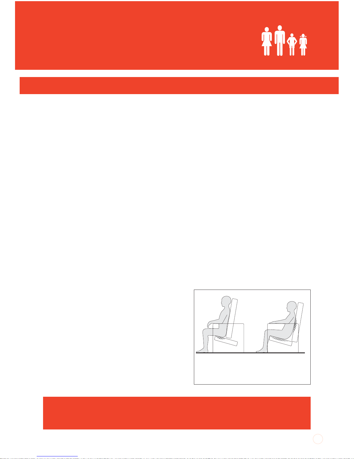
Seat Depth
It is important to set seat depth correctly in
order to prevent ‘sacral sitting’ and to achieve
the best distribution of weight between the
client and the chair. Sacral sitting occurs when
the pelvis tilts backwards so that the lower
back (sacrum), as well as the bottom, is resting
on the seat cushion. The sacral area can be
susceptible to pressure problems. Sacral
sitting will occur if the seat depth is too long.
If the seat depth is too short then the client’s
SAFETY NOTE
Seat depth should not be adjusted when a client is sat in the chair or
when the chair is tilted backwards.
Seat Too Short;
Increase in pressure
beneath the bottom.
Seat Too Long;
Increased pressure on
bottom, sacrum and
shoulders.
Page 8
SmartSeat
®
UI SmartSeat iss01, 03/2013
TM
body weight will be concentrated in too small
an area.
Seat depth should be set with the client’s
bottom positioned firmly at the back of the
seat cushion so that their lower back and
lumbar is supported by the back cushion.
There needs to be a two or three finger gap
between the client’s calf and the front of the
seat cushion for comfort.
If the client already has a chair or wheelchair
with the correct seat depth, measure this size
and use it to set up the SmartSeat chair.
Adjusting Seat Depth:
1. Seat depth is adjusted by moving the back
of the chair over the seat unit. The front edge
of the seat will stay in the same place. The seat
depth mechanism is controlled by a release
lever on the rear left hand underside of
the seat.
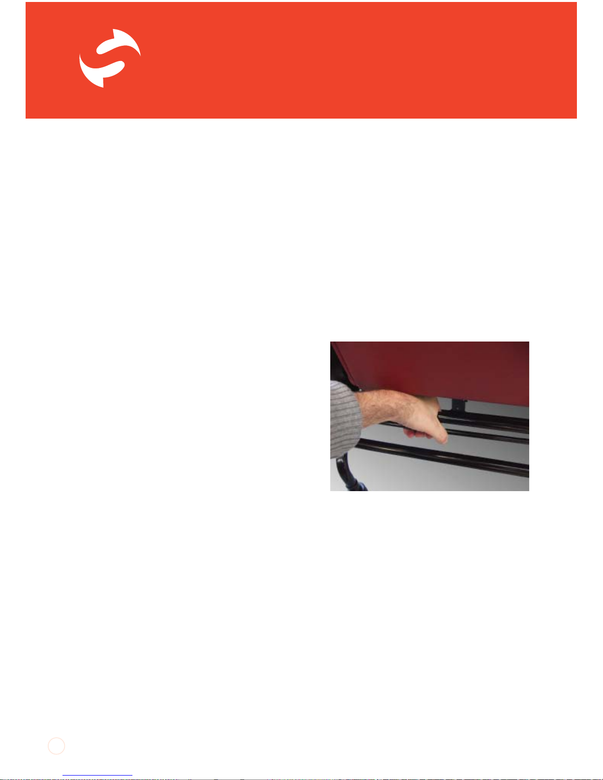
2. To adjust seat depth, locate the two rails
at the bottom of the back valance. Squeeze
the thinner rail up against the thicker rail to
release the mechanism controlling seat depth.
Keeping the two rails squeezed together, push
or pull the back of the chair to the desired
position. Once at the correct position, release
the lower, thinner rail. The back may jump back
slightly as the locking mechanism engages.
8
Squeeze the thin rail against the thicker rail to
release the seat depth mechanism.
Page 9
UI SmartSeat iss01, 03/2013
Seat Width
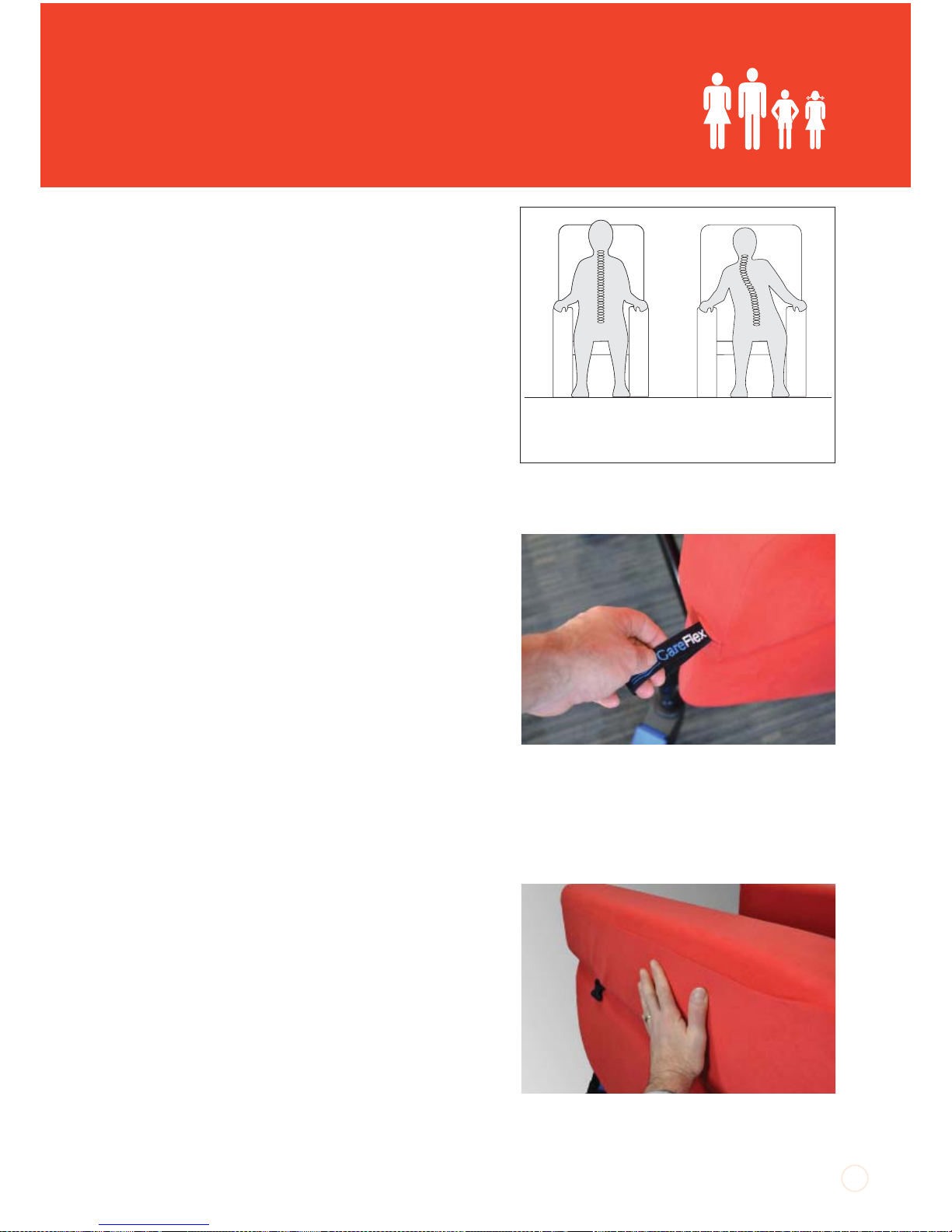
Seat width affects side-to-side pelvic stability.
This is important as the spine should line up
centrally with the pelvis. If the pelvis is free
to move to one side then the client’s spine
will usually lean in the opposite direction. As
gravity pulls the client over, the spine will begin
to curve to compensate as the client tries to
keep their head level. The client will take on
a characteristic ‘S’ shaped spine or scoliosis.
The more upright the user’s trunk is, the more
critical pelvic stability becomes. It is, therefore,
important to use a chair with the correct seat
width in order to position the pelvis properly.
Seat width should always allow for a little bit
of movement as the client’s body weight and
posture naturally shifts throughout the day.
If the client is held in a rigid position, they will
quickly tire and experience discomfort.
Adjusting Seat Width:
1. Each arm of the SmartSeat has a unique
adjustment mechanism which allows the arm
to be moved in or out relative to the centre of
the chair.
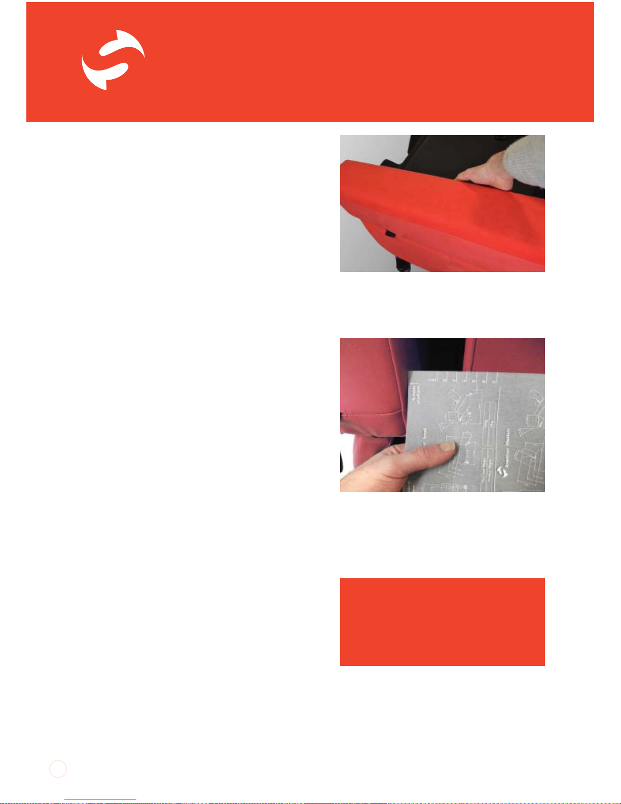
2. To release the mechanisms, locate the
tabs on the back of the arms. Pull the tabs
backwards until they stop. To reduce seat
width, by moving the arms in towards the
centre of the chair, place the palm of your hand
in the middle of the outside face of the arm
and push the arm inwards. To increase seat
width by moving the arms out from the centre
of the chair, place your hand in the middle of
the arm against the inside face and pull the
arm outwards.
9
Correct seat width;
client sits ‘midline’.
Seat Too Wide; client
tends to lean to one
side.
Pull the tabs on the back of the arms to
release the mechanism to adjust seat width.
Pull the tab out and push the middle of the
arm to reduce the seat width.
Page 10
SmartSeat
®
UI SmartSeat iss01, 03/2013
TM
3. Once the arm is in the desired position let
go of the tab. The arm may jump slightly as the
adjustment mechanism locks into the most
appropriate position. If the chair is unoccupied,
smooth out the lumbar cushion to minimize
wrinkling of the cover.
Checking Symmetry of Seat Width
Wherever possible aim to have the arms
adjusted symmetrically so that the client
is located centrally in the chair. Look at the
arms from the back of the chair and judge
distance from the inside face of arms to the
edges of the chair back frame. For the most
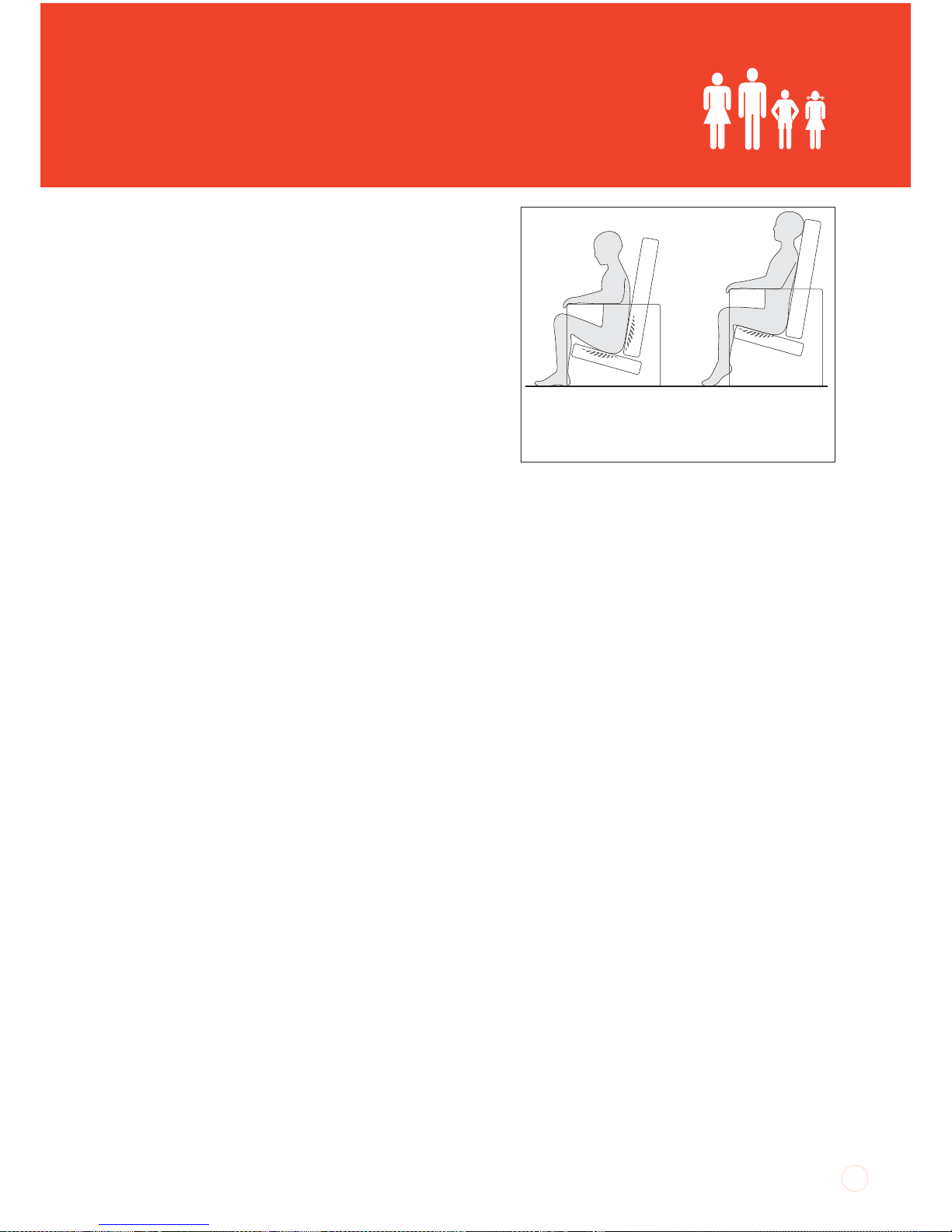
accurate set-up of seat width, use a rule or
tape measure or the incremental markings on
the back of these instructions to ensure the
adjustment of the arms is symmetrical.
10
SAFETY NOTE
Do not adjust seat width if the
occupant is leaning heavily onto the
arm you are trying to adjust. Do not
attempt to adjust seat width when the
tray accessory is fitted to the chair.
Pull the tab out and pull the middle of the arm
to increase the seat width.
Use a tape measure, rule or the guidelines on
the back page of these instructions to check
arm position and symmetry.
Page 11
UI SmartSeat iss01, 03/2013
Seat Height
If the client can raise to standing themselves or
with minimal assistance, the seat height should
be set so that the client’s feet rest flat on the
floor and the underside of their thighs are in
contact with the full length of the seat cushion.
If the seat height is too high, the client’s heels
will be lifted off the floor and pressure will build
up along the underside of their thighs. If the
seat is too low, their knees will be raised and
there will be no contact between the back
of their thighs and the seat cushion. This will
increase the pressure on their bottom and
sacrum and could cause discomfort at the
hips.
If the client is less ambulant and is being
regularly portered then seat height can be set
relative to the footplate. Again, ensuring the
foot is flat and fully supported is important.
The SmartSeat chair seat height will have been
measured during assessment and the chair
made to these dimensions for the client prior
to delivery.
Further Adjustments
If further adjustment is required, please
contact your local CareFlex Distributor or
contact CareFlex for the additional ‘SmartSeat
Chair Seat Height Adjustment’ User
Instruction document.
11
Seat Too Low;
Increase in pressure on
the buttocks and lower
back.
Seat Too High;
Increase in pressure
beneath thighs.
Page 12
SmartSeat
®
UI SmartSeat iss01, 03/2013
TM
Brakes
During transfer it is important that the chair
is as stable as possible. The chair is fitted with
four fully braked castors and the brakes on at
least two castors should be engaged before
transfer.
Locking the Brakes:
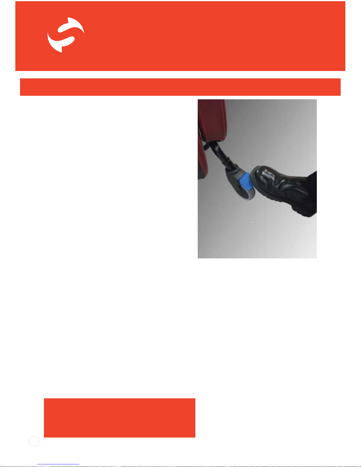
1. To lock the brakes, position the chair
approximately where you need it to be for
transfer. Gently push the chair away from you
so that the castors swivel around so that the
blue brake levers can be easily accessed.
2. Press down the end of the blue brake levers
with your foot. The lever will angle down and
click into the locked position.
Releasing the Brakes
To release the brakes, gently kick the end of
the lever which is pointing upwards. The lever
will snap down and the castors will roll freely.
Tilt-in-Space
The SmartSeat chair has a Tilt-in-Space facility
which allows the client to be reclined without
adjusting the angle at the hips. This helps the
client to maintain a stable sitting posture whilst
distributing their weight over a large surface
area.
12
The SmartSeat Chair in Day to Day Use
Each castor has a brake.
Apply at least two before transfer.
SAFETY NOTE
When tilting the SmartSeat chair forward,
ensure the footplate height is set so that the
footplate will not hit the f loor.
Page 13

UI SmartSeat iss01, 03/2013
Tilt-in-Space should be regularly adjusted to
facilitate an easy change in weight distribution,
thus avoiding pressure build up in any one area.
Always warn the client before changing Tiltin-Space to ensure they do not become
distressed or agitated.
The chair will Tilt-in-Space 20
°
backwards. This
degree of tilt may be disconcerting for some
clients. Please ensure the client is comfortable
and does not become distressed if they are
fully tilted backwards.
Adjusting Tilt-in-Space:
1. Manual Format
On the manual option the Tilt-in-Space feature
is controlled by the large lever on the push
handle.
To adjust the Tilt-in-Space, squeeze the lever
and tilt the chair to the desired angle. Release
the lever to hold the chair at the desired angle.
2. Motorised Format
On motorised chairs, the second row of
buttons on the handset control the Tilt-inSpace movement.
SAFETY NOTE
It is essential to regularly check the adjustment
of the seat to footplate height to ensure it does
not hit the ground when lowered. When the chair
is tilted backwards it is possible to extend the
seat to footplate height so that it is greater than
the seat to floor height. However, if the chair is
tilted forward when the seat to footplate height
is fully extended the footplate may hit the floor
and damage the legrest mechanism. This is
especially important if the chair is in its lowest
seat to floor height setting.
13
Page 14
SmartSeat
®
UI SmartSeat iss01, 03/2013
TM
Legrest Elevation
The SmartSeat chair has an integral legrest
which can be angled upwards to support
the legs. The patented legrest mechanism
articulates, following the movement of the
knee as it elevates the legs. The legrest
incorporates visco-elastic memory foam for
pressure relief.
Ensure the legrest is fully lowered before
transferring a client to or from the chair.
The range of legrest elevation is from 80° at
the knees to 170
°
. Over-elevating the legs can
cause tightness in the hamstrings which could
cause discomfort. A legrest cannot be used
to ‘straighten’ contractures in the knees and
close attention needs to be paid to the angle
of elevation and for how long legs are elevated
to ensure good positioning and continued
comfort.
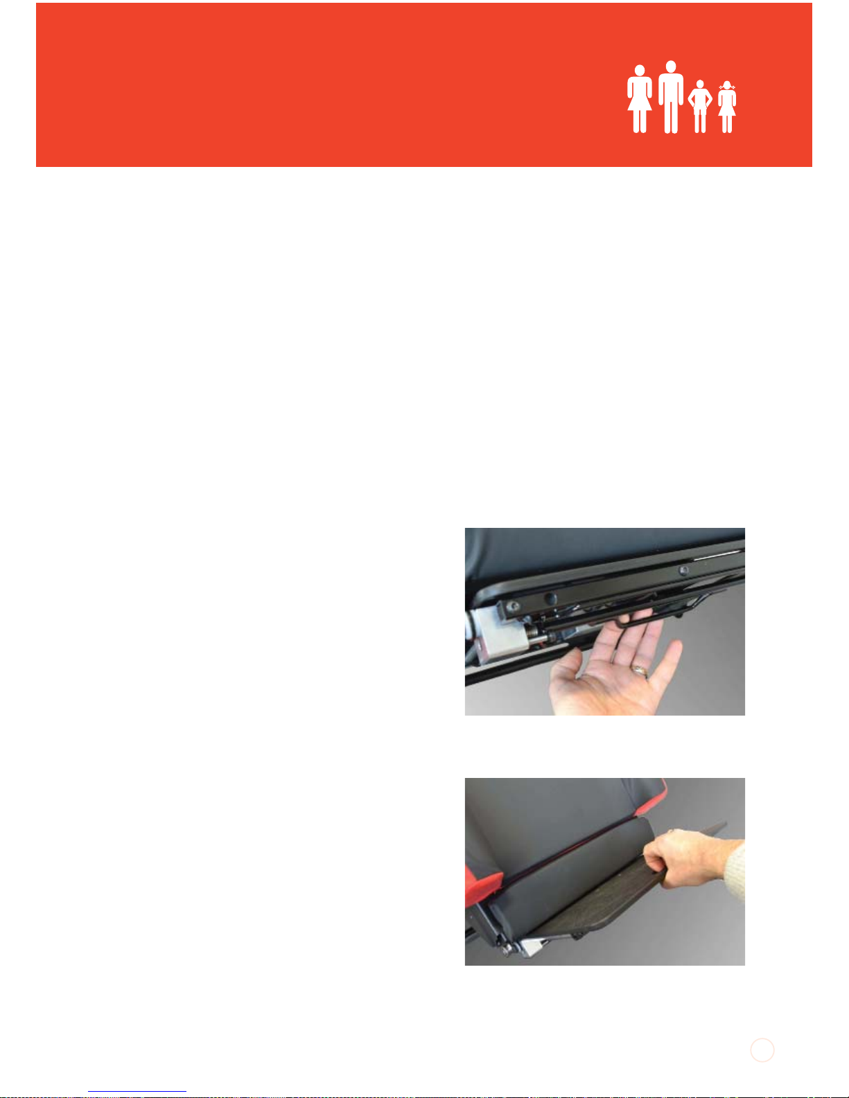
Adjusting Legrest Elevation:
1. Manual Format
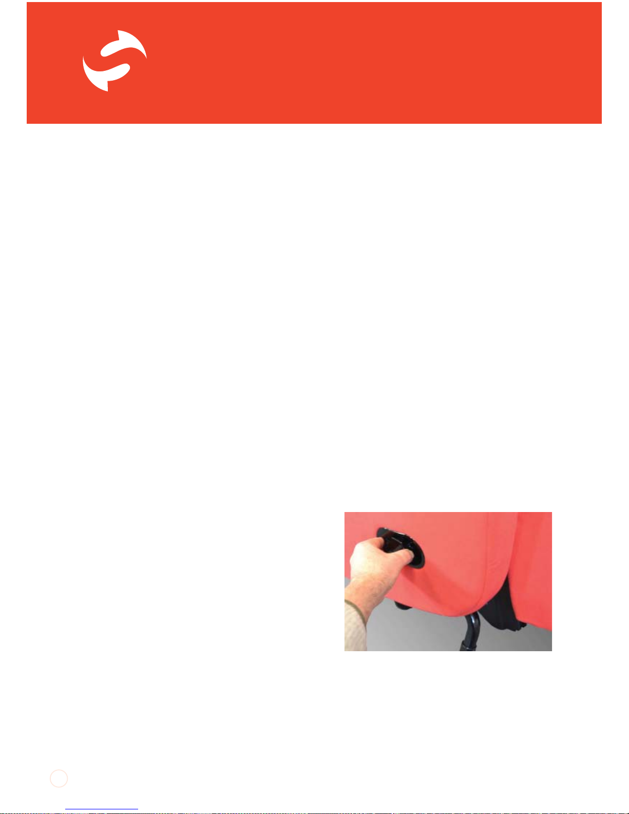
On the manual option of the SmartSeat chair,
legrest elevation is controlled by the lever
located on the right hand side panel. Pull this
lever out and the legrest will begin to raise. It
may be necessary to lift the legrest towards its
maximum elevation, depending on the
weight of the client’s lower legs. Once the
legrest is at the desired angle, release the lever.
To lower the legrest, pull the lever out and the
legrest will return to its lowered position. It may
be necessary to push the legrest down if the
client has weak or light lower legs.
14
Manual operation legrest lever on the right
side of the chair.
Page 15
UI SmartSeat iss01, 03/2013
15
2. Motorised Format
On the motorised option, legrest elevation
is controlled by the handset. The top row of
two buttons control legrest elevation. The
left hand button raises the legrest. The right
hand button returns the legrest to its lowered
position.
Integral Footplate
The legrest has an integral height and angle
adjustable footplate to provide support to
the client’s feet when the legrest is raised or
when they are being portered in the chair. The
footplate is stowed away behind the legrest.
Accessing the Footplate
Tilting the chair back and elevating the legrest
gives better access for deploying the footplate.
The first few times the footplate is used it
will be easier to position the chair like this so
that familiarity with the process can be easily
developed.
Deploying the Footplate:
1. To deploy the footplate look for the front
edge of the footplate sticking out from the
bottom of the legrest. Locate the release
handle centrally located at the back of the
footplate. Twist the handle out and the
footplate will drop forward. Grip the recess on
the front edge of the footplate and pull the
footplate out. Continue to pull the footplate
until it is felt to click into its locked, 90° position.
2. At this point the footplate will look short.
A further tug on the front edge of the
footplate extends the support surface. At full
extension the foot support surface should be
approximately 26cm from front to back.
central release handle to deploy the footplate
Grip the centre of the footplate to extend the
foot support surface.
Page 16
SmartSeat
®
UI SmartSeat iss01, 03/2013
TM
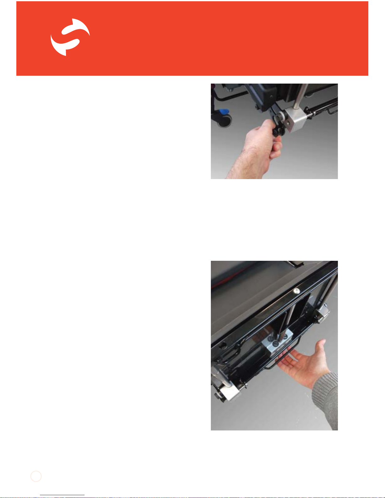
Footplate Angle / Plantar Flexion Control
The footplate has three angle settings to
provide comfort and support plantar flexion.
As the legrest is elevated, having a 90° angle
at the ankle will become more uncomfortable.
The footplate can be angled down to provide a
more relaxed position.
Adjusting Footplate Angle
To adjust the angle, locate the round knobs
mounted each side of the back corners of
the footplate. Pull out the knobs and tilt the
footplate to the desired angle. Release the
knobs and they will click into the nearest angle
setting.
Stowing the Footplate:
1. To fold the footplate up and store it behind
the legrest the legrest must be set at its 90°
angle position. See ‘Footplate Angle / Plantar
Flexion Control’ for instructions on how to do
this.
2. Once the footplate angle is at 90°, give the
front edge of the footplate a sharp tap and
push the footplate in to its minimum depth.
3. Reach under the footplate and locate the
release handle. Pull this out and the footplate
will start to drop back. Keep pushing the front
edge of the footplate and it will swing up
behind the legrest. A further sharp push at the
end of the movement will lock the footplate in
its stowed position.
16
Pull out the round knob on each side of the
back edge of the footplate to adjust footplate
angle
Pull out the release handle to get the
footplate to drop back behind the legrest for
stowing
Page 17
UI SmartSeat iss01, 03/2013
Seat to Footplate Height
The SmartSeat chair has an articulating legrest
which has a naturalistic movement to provide
support to the lower leg as the knees flex. This
means that for the majority of occupants the
footplate will provide consistent support as
the legrest elevates. However, it is sometimes
necessary to make seat to footplate height
adjustments as a consequence of knee
position not working in harmony with the
action of the legrest.
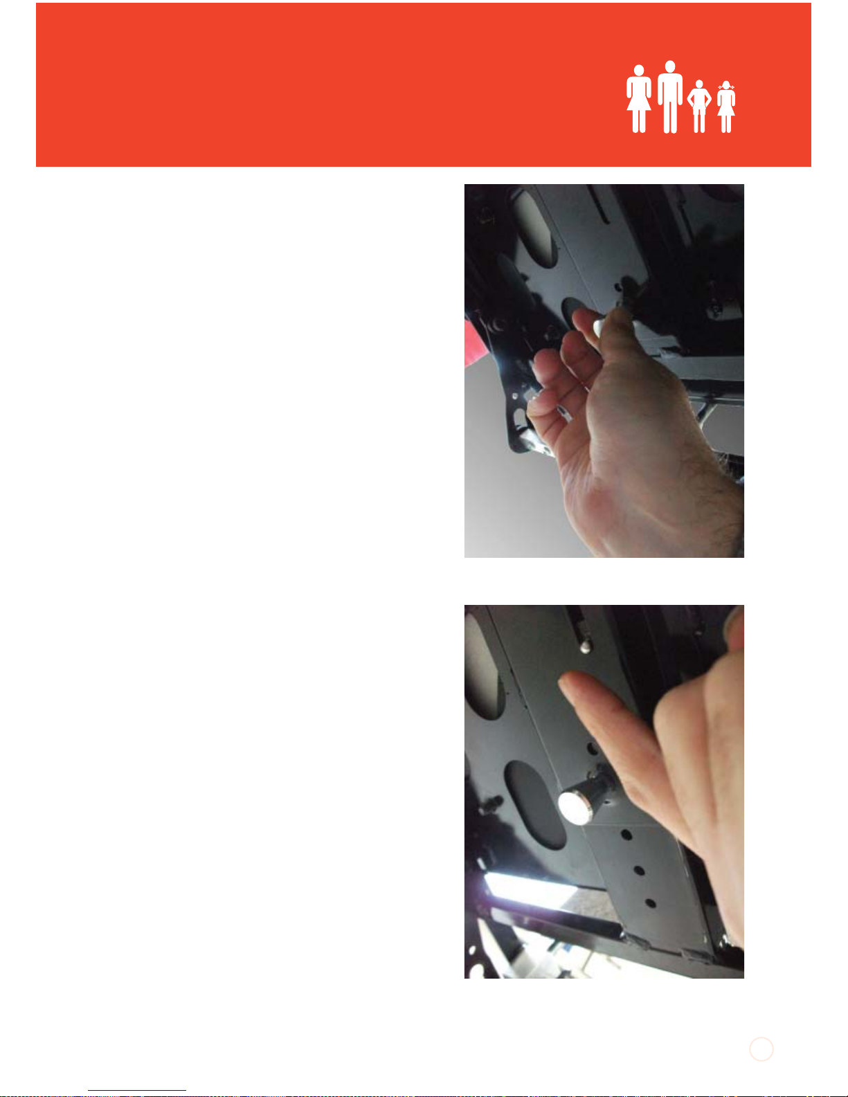
Adjusting Seat to Footplate Height:
1. To adjust seat to footplate height, deploy
the footplate and locate the indexer on the
footplate receiver mounted centrally on the
back of the legrest.
2. Pull the indexer out and lift/lower the
footplate to the desired position. Once at
the desired position, release the indexer. The
footplate may drop slightly as the indexer
locates in the closest height setting.
Footplate Removal and Re-fitting
At some point the footplate may not be
required. The footplate can be removed if this
is the case.
Removing the Footplate
To remove the footplate, stand at the right
side of the chair and elevate the legrest to
maximum. Locate the indexer controlling seat
to footplate height, pull it out and at the same
time pull the footplate out until you feel it hit
its maximum stop. On the right side of the
indexer, feel for a small round button. Press
this in and the footplate assembly will slide free
of the receiver on the legrest. Be prepared to
take the weight of the footplate assembly as it
comes free of the legrest.
17
Indexer for seat to footplate height
adjustment
Retaining button. Press in to slide footplate
out completely.
Page 18
SmartSeat
®
UI SmartSeat iss01, 03/2013
TM
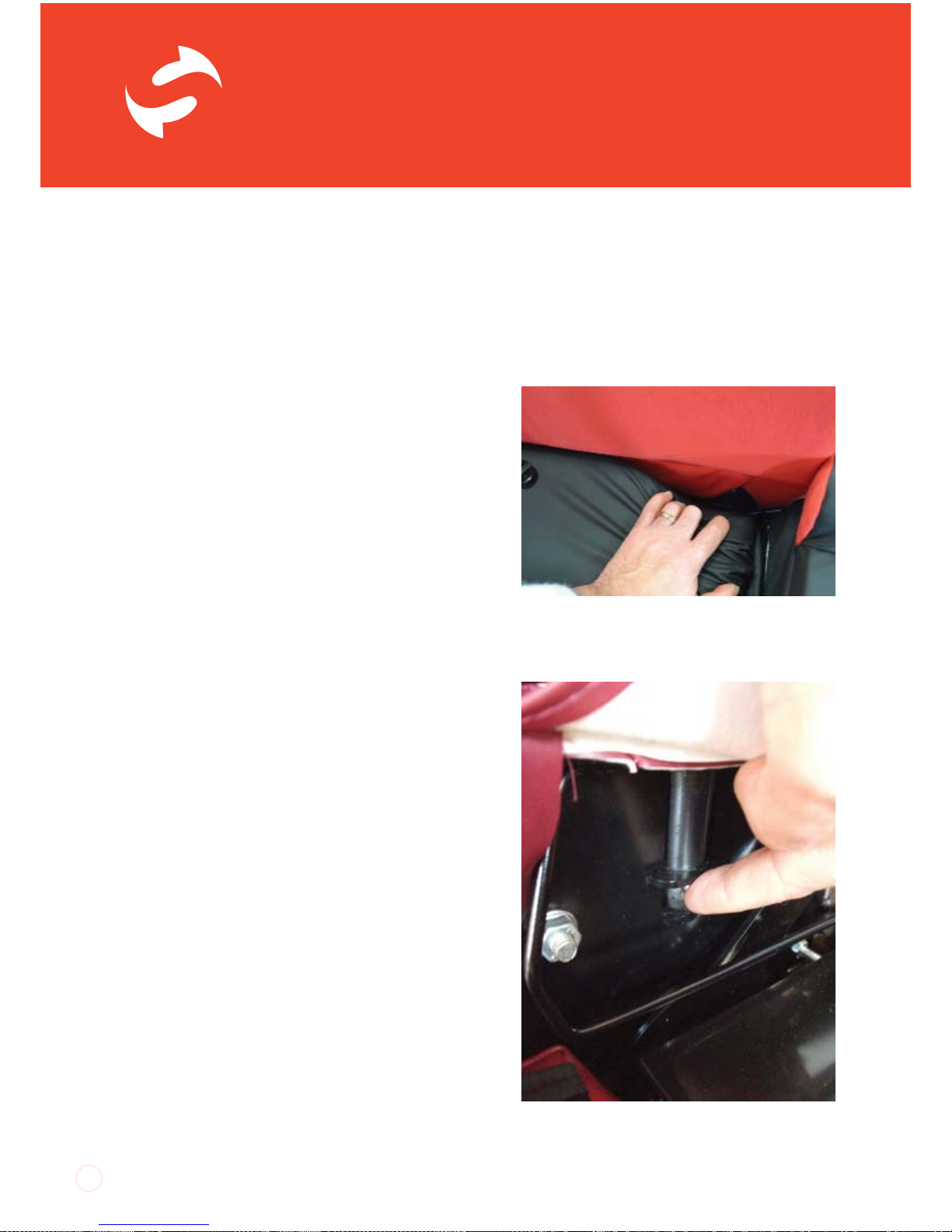
Re-fitting the Footplate
To re-fit the footplate assembly, present
the rectangular tube of the assembly to the
receiver on the back of the legrest. Push in the
small button on the top edge of the tube so
that it can slide into the receiver. Adjust the
footplate to the desired height.
SmartSeat Arms
Arm Removal and Side Transfer
The arms of the SmartSeat chair can be
removed for servicing and for side transfer. If
the intention is to regularly remove the arms
then the arm location locking device can be
disabled so that the arms can be lifted off the
chair easily.
Occasional Arm Removal:
1. Detach the tabs which hold down the front
edge of the seat cushion. Plastic ‘J’ strips are
sewn onto the ends of these tabs and clip on
to thin round bars on the underside of the front
edge of the seat board.
2. Push the front of the cushion to one side
to reveal the side cover attachment. Unclip
the ‘J’ strip at the front top corner of the side
cover. Hold the cover up and locate the vertical
tube which is the front location point for the
arm. At the end of the tube you will see a small
round button. This is the locking device which
prevents the arm being inadvertently removed
from the chair. Press this button in to the tube
and lift the arm clear of the chair. You may
need to angle the arm outwards to clear the
underside of the wing if seat depth is adjusted
towards the minimum setting.
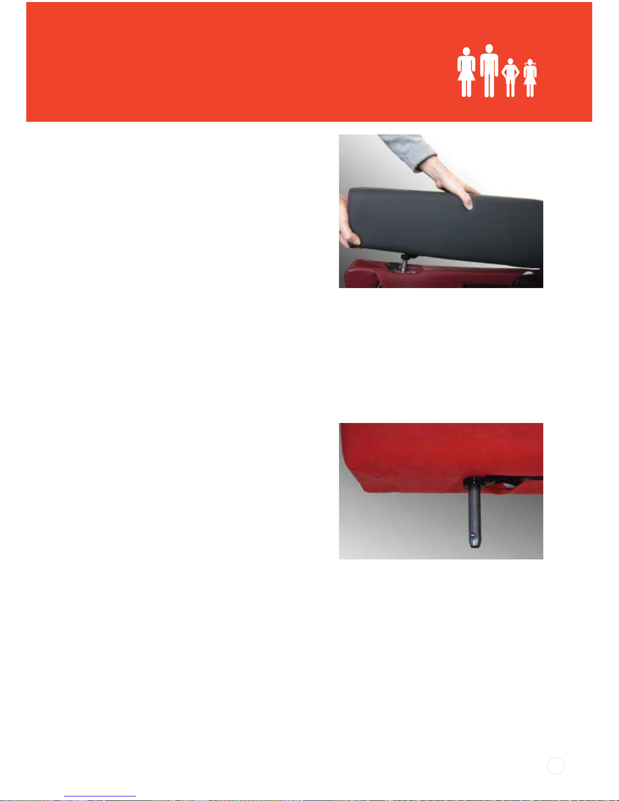
18
Front location point for arm fitment.
Depress the button to release the front arm
mounting peg
Page 19
UI SmartSeat iss01, 03/2013
3. Re-fit the arm by reversing the above
process.
Frequent Arm Removal:
1. If the arm is going to be removed frequently,
as would be expected if regular side transfers
are being made, the locking device can be
disabled. To do this you will need a pair of longnosed pliers. This should not be done to chairs
in multi-user environments or where people
with challenging behaviour may unintentionally
remove the arm.
2. Remove the arm as described above. With
the arm off the chair, depress the small round
button of the locking device into the front arm
mounting peg. Take a pair of long-nosed pliers
and whilst holding the small button down, push
the pliers up into the bottom end of the tube.
This will push the small button past its locating
hole and prevent it popping out and disabling
the locking device.
3. To reinstate the locking device, use longnosed pliers to carefully grip the end of the
small button and pull and twist it around so that
it pops back through its locating hole.
19
Lift the arm off the base sides
If arms are beiong frequently removed, the
button in the mounting peg needs to be
depressed and then pushed up into the tube
Page 20
SmartSeat
®
UI SmartSeat iss01, 03/2013
TM
Accessories and Options
Contoured Back
As with all CareFlex chairs, a contoured back
option is available which offers simple lateral
support, helping to limit leaning and give
additional control during upper
trunk movement.
When ordered as an option on a new chair
the Contoured back consists of a medium
density foam profile which has sculpted sides
to provide support to the sides of the ribcage.
This support is in place above arm height as
the seat width adjustment system allows for
accurate control of lateral hip position.
Retro-fitting Contoured Back
A contoured back can be fitted to a chair
which was originally ordered with a flat
back. A replacement or retro-fit contoured
back consists of the profiled foam and an
appropriately shaped cover.
Fitting Instructions:
1. To fit a contoured back you will need a
13mm spanner or socket wrench. Begin by
unclipping the sides of the chair back valance.
There are plastic ‘J’ strips sewn to the edges
of the valance. These clip over thin bars which
make up part of the structure of the chair back.
Starting at the lower sides, unclip the valance
until it can be folded over the top of the chair
back.
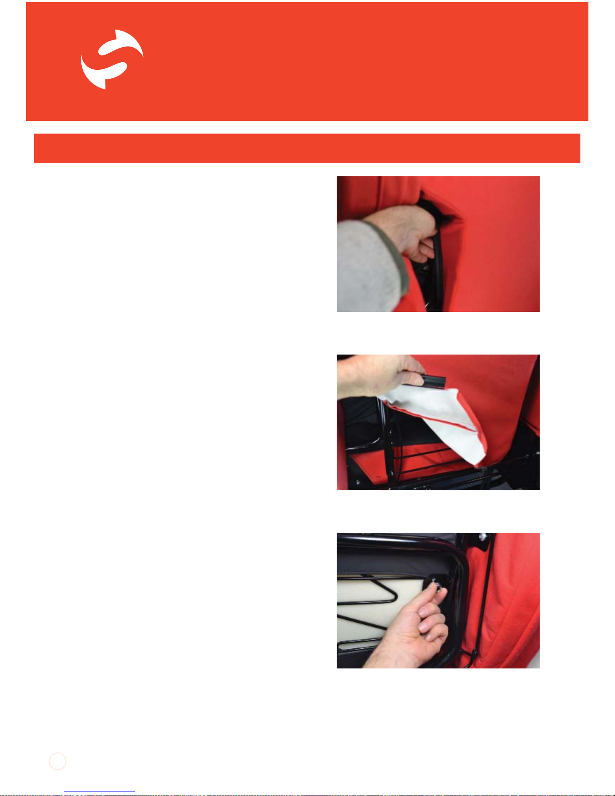
2. Detaching the valance reveals the three
back cushion frames. Identify the middle frame
and look for the nuts in each corner which hold
the frame in place. Undo the nuts and keep
them safe, ready to re-fit the frame.
20
Grip the J strip at the top and un-clip from the
thin side bar
Continue around the bottom edge of the
valance.
Remove the flange nut at each corner of the
middle cushion wire to remove the middle
cushion.
Page 21
UI SmartSeat iss01, 03/2013
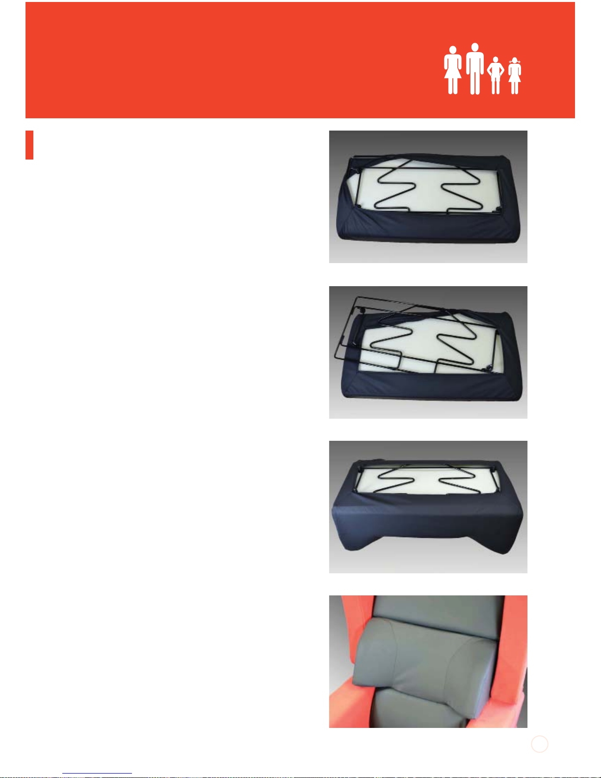
3. Lift the middle back cushion off from the
front of the chair. The cover fits over the frame
and foam to keep the foam in place. Carefully
twist the frame out of the cover, one corner at
a time. The foam can then be compressed and
pulled out of the cover.
4. Fit the contoured foam into the contoured
cover, noting that the foam will only go in one
way because of the shaping of the contours.
Once the foam has been inserted into the
cover and generally aligned, fit the frame into
the cover as well. The ‘Christmas Tree’ shaped
profiles need to point up as the top edges of
the contours angle down. Put one side into the
cover first, pulling the frame over the threaded
studs which are used to bolt the frame in place.
The cover can then be pulled over the opposite
side. Pull the cover straight so that the corners
of the cover sit neatly around the four studs on
the frame. Keep on manipulating the foam until
the cover and the corners are filled out by the
foam and look neat.
5. Fit the frame onto the chair back between
the top and lumbar cushions and fasten it in
place with the nuts removed earlier. Re-fit the
back valance.
21
Wire removed off one corner
Wire pulled out sideways
Wire fitted into contoured back cover.
Page 22
SmartSeat
®
UI SmartSeat iss01, 03/2013
TM
Adjustable Laterals
Adjustable Laterals can be fitted to SmartSeat
chairs with the flat back option. The adjustable
laterals have height and width adjustment
to provide support to the sides of the rib
cage. The adjustable laterals can be retro
fitted to any SmartSeat chair. Each lateral is
adjusted independently. The objective of using
supports like adjustable laterals is to position
the client as upright and as close to a ‘midline’
position as possible so that pelvis, spine and
head are aligned in a vertical column. However,
adjustable laterals can also be used to support
asymmetric postures. In all situations, adjust
laterals to fit against the skeleton, i.e. the ribs.
If the lateral is positioned too low down it is
likely that the occupant will end up leaning over
the top edge of the lateral. The adjustable
laterals should be adjusted so that there is a
two finger gap between the top edge of the
lateral and the occupant’s axilla (arm pit).
Height
The Adjustable Laterals have a 15cm range of
height adjustment. The height of the laterals is
set with a clamping lever.
Adjusting the Height:
1. To adjust the height of the laterals, flick the
lever up so that it feels loose.
2. Hold the lever and the lateral pad itself
and raise or lower the lateral tot the desired
position.
3. Fold the lever back down to lock the height
of the lateral.
22
SAFETY NOTE
The adjustable laterals should not
be used to control trunk position
for someone who is highly agitated,
specifically for those who rock back
and forth. There is a danger that if
an occupant leans forward and then
rocks back they may injure their
back against the firm support of the
laterals.
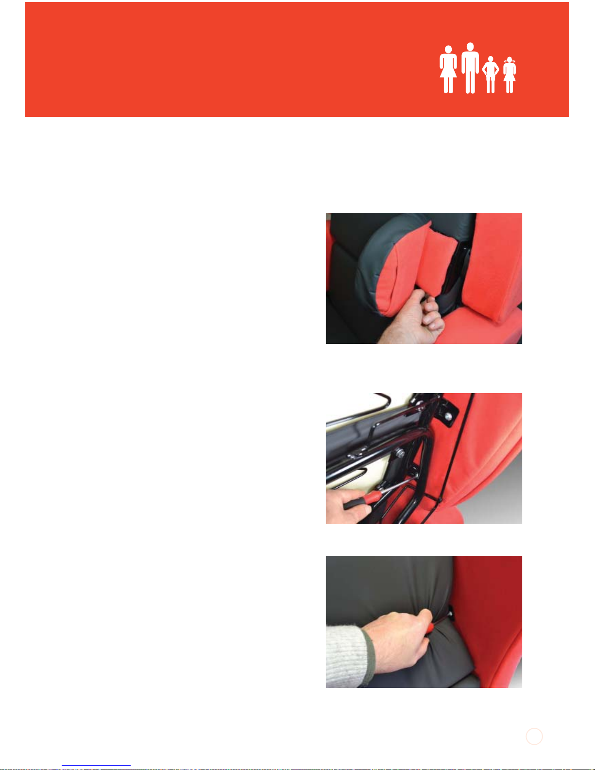
Lift up the cam lever to adjust lateral height.
Page 23
UI SmartSeat iss01, 03/2013
Width
The Adjustable Laterals have 5cm of width
adjustment in 1cm increments. The width
position is controlled by a pull-out indexer.
Adjusting the Width:
1. To adjust the position of the laterals, pull out
the indexer and, whilst holding the lateral pad,
slide the lateral to the desired position.
2. Once at the desired width, release the
indexer and ensure it has registered in the
nearest appropriate increment.
Retro-fitting Adjustable Laterals
The support assembly of the adjustable
laterals are positioned on the chair between
the wings and the back frame. To retro-fit the
adjustable laterals you will need a 5mm allan
key. A ball-end allan key makes the job easier.
1. Begin by unclipping the sides of the chair
back valance. There are plastic ‘J’ strips sewn
to the edges of the valance. These clip over
thin bars which make up part of the structure
of the chair back. Starting at the lower sides,
unclip the valance until it can be folded over
the top of the chair back.
2. The fastening which hold the wings in place
on the chair back need to be partially undone.
There are two lower fastenings behind the
back cushions and two higher fastenings
hidden by the cushion of the top back section.
3. Compress the sides of the top back cushion
to reveal the two top fastenings. Use a 5mm
allen key to partially undo these fastenings.
Five complete turns of each fastening will
be sufficient for fitting the adjustable lateral
23
Pull out the indexer to adjust lateral width.
Remove the vallance and undo the two lower
wing mounts with a 5mm ball end allan key.
Use a 5mm ball end allen key to loosen the
second from top wing mount
Page 24
SmartSeat
®
UI SmartSeat iss01, 03/2013
TM
connectors.
4. Go to the back of the chair and undo the two
lower fastenings by the same amount.
5. The adjustable laterals come in handed pairs
and the left and right can be identified when
the indexer controlling width adjustment is on
the bottom edge of the lateral assembly. The
adjustable lateral connectors fit over the two
lower fastenings. Taking the adjustable lateral
for the appropriate side, carefully slide the
connectors between the wings and the two
lower fastening mounting plates. The hook
shaped cut-outs on the connectors slide over
the fastenings.
6. Once in position, re-tighten all fastenings
and clip the back valance back in place. For
ease, clip the bottom of the valance in place
before the sides.
Headrests
The complete range of CareFlex headrests are
available for the SmartSeat chair. These are
attached to the thin round bar between the
push handles on the back of
the chair. Each headrest has a strap attached
to its top edge. The straps have short strips of
plastic hook profile sewn at intervals along its
length.
Positioning the Headrest
Position the headrest at the appropriate height
for the chair occupant, pull the strap tight
over the top of the chair and clip the most
appropriately positioned plastic hook over the
round bar between the handles.
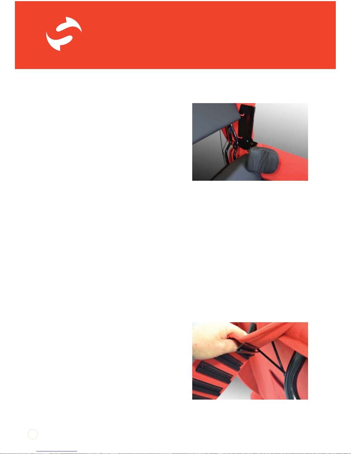
24
Fitting adjustable laterals between the back
frame and wings (middle cushion removed
for clarity)
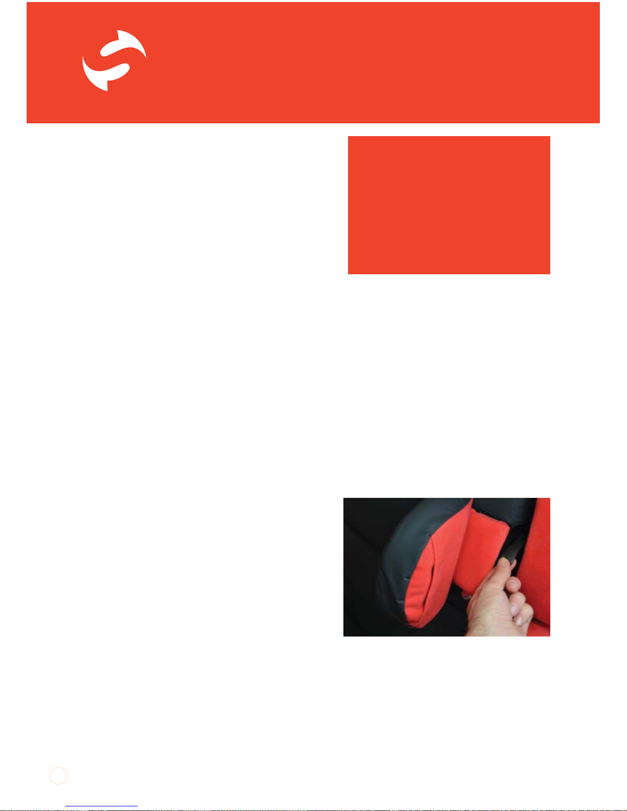
Fitting headrest straps to the bar between
the push handles.
Page 25
UI SmartSeat iss01, 03/2013
25
Pommel
A pommel can be used to control knee
position, usually by abducting (pushing apart)
the knees to help keep the seating position
stable and level. The pommel is designed to
separate the knees and support the whole
inside of the knee joint. For this reason the
pommel is not depth adjustable and sticks out
in front of the seat edge.
A pommel must never be used as a restraint
and the client must not be allowed to slide into
sacral sitting and come to rest against the
pommel.
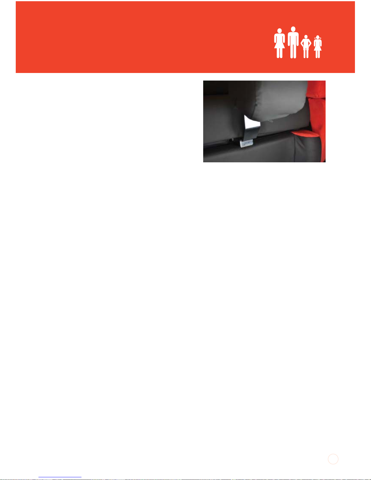
Fitting the Pommel:
1. Fit the pommel with the legrest angled down
as this will give the best access to the receiving
bracket.
2. To fit the pommel, locate the square hole in
the loose flap of fabric between the top edge
of the legrest and the underside of the seat
cushion. The receiving bracket for the pommel
is located under the front edge of the seat
cushion behind the square hole.
3. Fit the metal stem of the pommel through
the square hole, into the receiving bracket
and push the pommel until it is felt to click into
position.
Removing the Pommel
To remove the pommel, hold it at the bottom
edge of the metal stem and pull directly
outwards.
Pommel f itted and removed when the legrest
is fully lowered.
Page 26
SmartSeat
®
UI SmartSeat iss01, 03/2013
TM
Pommel Receiving Bracket Fitting
If ordered with a chair, the pommel receiving
bracket will be fastened in place. If retro-fitting
a pommel to an existing chair, the receiving
bracket will need to be fastened in place on the
seat frame. You will need a 5mm allan key and
two 13mm spanners to do this.
Fitting Instructions:
1. Undo the zip which attaches the crumb
catcher on the front of the seat cushion to the
top of the legrest.
2. The seat is held in place by two tabs on the
front edge and a large tab on the back edge.
The tabs have plastic ‘J’ strips sewn onto them
which clip over thin bars on the seat frame
beneath the front and back edge of the seat
board. Unclip the ‘J’ strips and lift the seat
cushion out of the chair.
3. Use a 4mm allan key to undo the four fixings
which hold the seat board in place. Put the
fixings in a safe place ready for re-positioning
the board.
4. Locate the two holes drilled horizontally
through the front cross tube of the seat frame.
Position the pommel receiving bracket against
these holes. Ensure the nut welded to the
underside of the tube is facing down.
5. Fit the two bolts supplied with the bracket
through the holes in the bracket plate and the
holes in the seat frame cross tube and fasten
the bracket in place with nyloc nuts. Spanners
must be used to tighten the bracket in place.
6. Re-fit the seat board and cushion. Ensure
the ‘J’ strips on the seat cushion tabs are
clipped securely in place front and back.
Smooth out the seat cushion under the back.
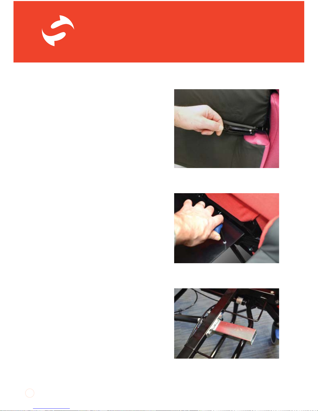
26
Removing the seat board.
Pommel bracket fitted to front cross tube of
seat frame.
Separating the two halves of the crumb
catcher which joins the seat to the legrest.
Page 27
UI SmartSeat iss01, 03/2013
Belts and Harnesses
CareFlex pelvic belts and harnesses are
designed to be used as positioning aids to
help the client maintain a good sitting posture
whilst reducing the risk of soft tissue damage
through the effects of shear which can occur if
the client has an unstable posture.
A level of supervision appropriate to the client’s
abilities must be applied at all times.
Pelvic Belts
Pelvic Belts are designed to stabilize the pelvis
and keep the client in an upright, functional
position.
All pelvic belts need to be correctly adjusted
to adequately support the client without
restricting breathing or causing discomfort. It
is essential that a pelvic belt is not adjusted to
fit loosely around the client and is not allowed
to work loose over time as this will allow the
client’s pelvis to tilt backwards, encouraging
them to slide down and forward in the chair.
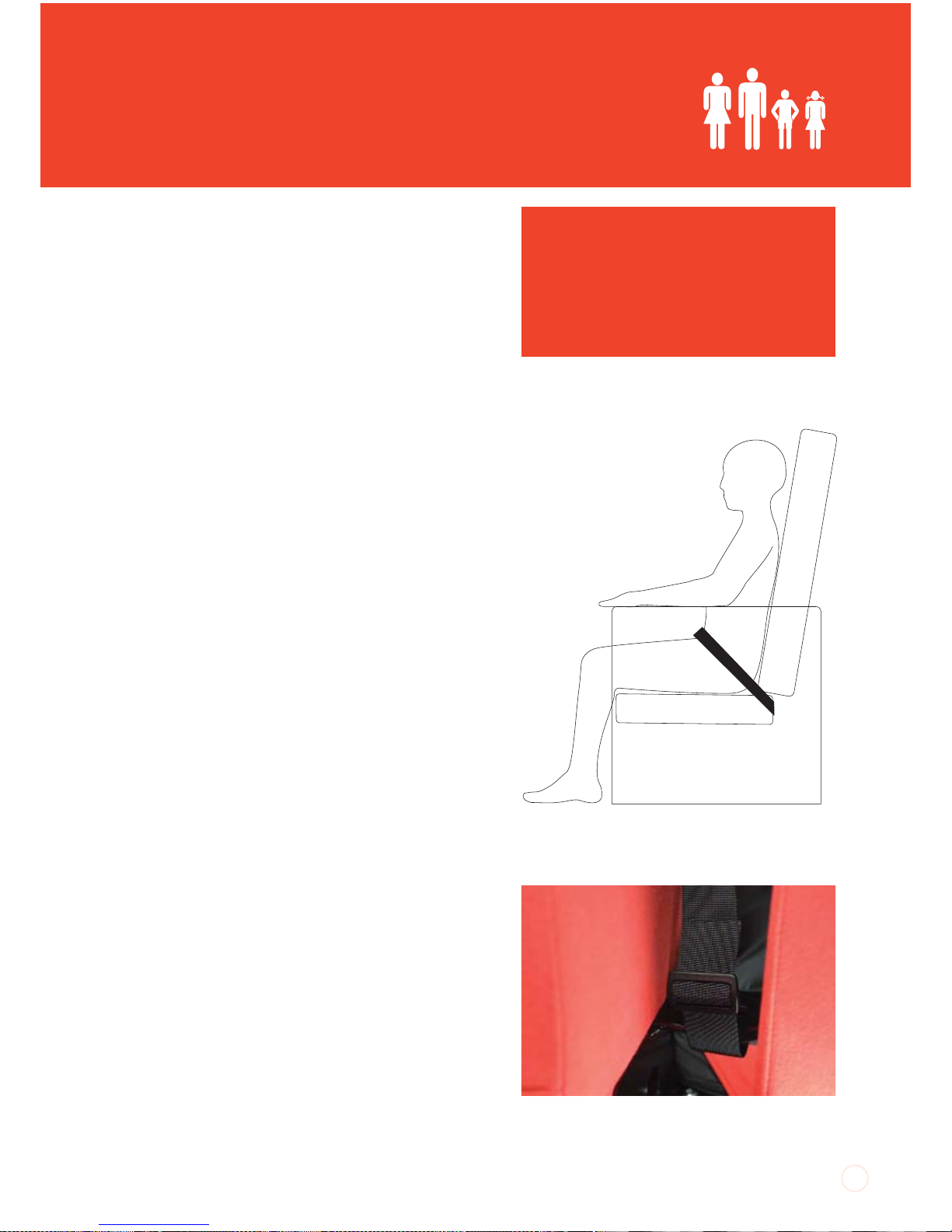
CareFlex pelvic belts are intended to pull back
over the hips at an angle between 45° and 60°.
This angle helps to maintain a vertical pelvis by
simultaneously pulling the hip joint down and
back.
Fitting Pelvic Belts
The pelvic belts are attached to the anchor
bars on the rear bottom edge of the back
frame each side of the valance. Thread the
end of each webbing strap through a triglide buckle. Loop the webbing around the
27
WARNING
The use of pelvic belts and harnesses
must be thoroughly risk assessed by a
healthcare professional. Appropriate
training in their function, adjustment
and operation must be provided for all
those who use them.
Pelvic Belt coming over the hips between 45°
and 60° degrees.
Pelvic strap fitted around the back frame
tube and held in place with a tri-glide.
Page 28
SmartSeat
®
UI SmartSeat iss01, 03/2013
TM
28
mounting bars and re-thread the end of the
webbing through the tri-glide. Adjust the
length of the belt by threading more or less
webbing through each tri-glide buckle.
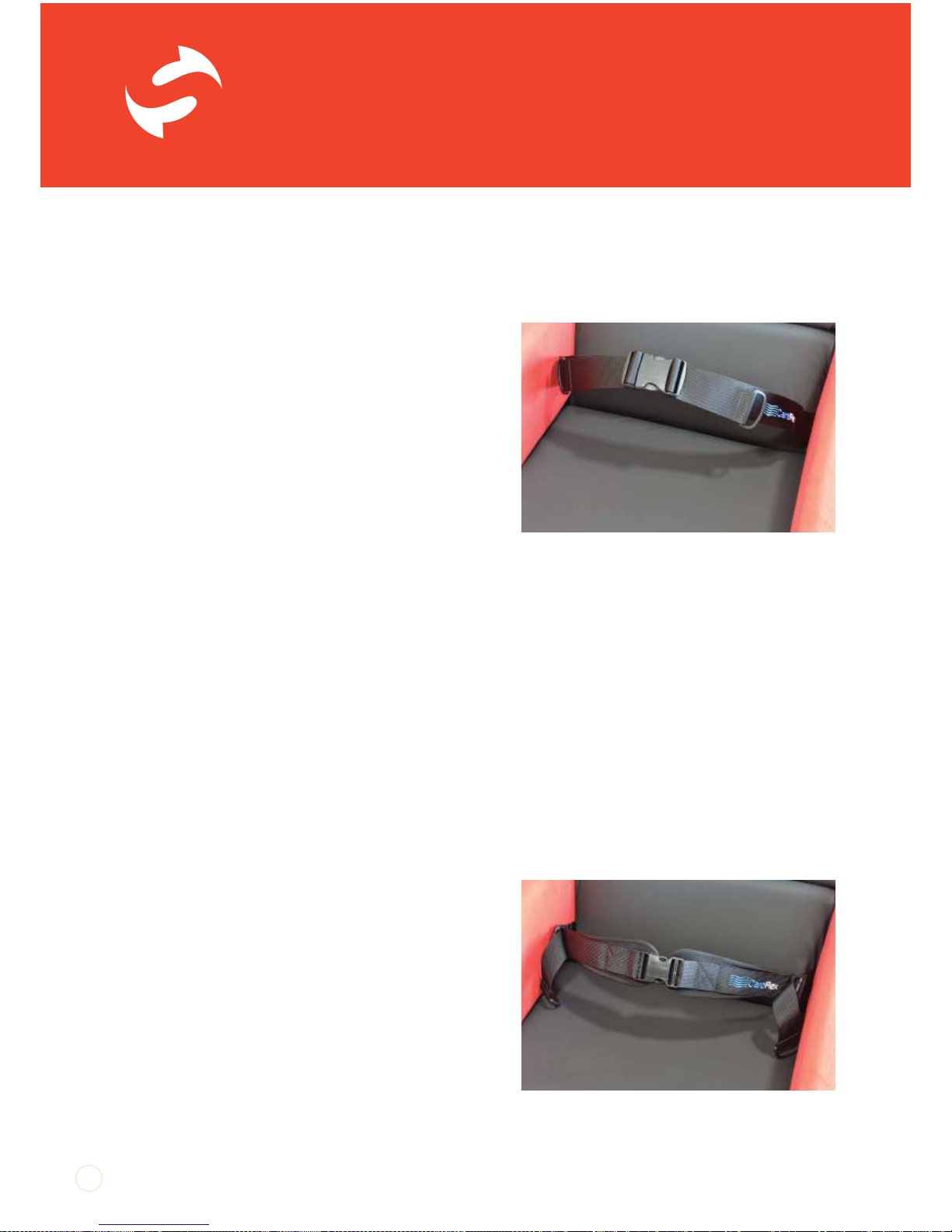
Plain Pelvic Belt
The Pelvic Belt is a simple strap made from
50mm webbing with a double adjustable
side release buckle. It is intended for use as a
safety strap when portering a client in a chair.
As it is not padded, it will not be particularly
comfortable as a long-term positioning aid.
Plain Pelvic Belt Set-up:
1. Adjust the webbing through the side release
buckle so that there is approximately 15cm of
loose webbing each side. Set the main length
of the belt through the tri-glide buckles on the
rear bottom edge of the back frame.
The belt should be sufficiently tight to support
and control the pelvis without being painful.
2. In day to day use clip the two halves of
the side release buckle together once the
occupant is sat in the chair. Additional tension
can be applied to the belt by pulling
the D-rings which will draw the webbing through
the buckle.
3. To open the belt, press the tabs on the sides
of the buckle so the two halves spring apart.
Padded Pelvic Belt
The Padded Pelvic Belt is ‘rear pull’, so that day
to day adjustments are made by pulling D-rings
on the webbing straps which adjust in length
through ladder lock buckles on the ends of the
comfort pads. The main adjustment is set at
the mounting points. The comfort pads are
Plain pelvic strap fitted. Adjustment straps
through buckle.
Padded pelvic belt. Adjustment is made at
the rear end of the pads.
Page 29
UI SmartSeat iss01, 03/2013
made from neoprene.
Padded Pelvic Belt Set-up:
1. To set up the overall length of the belt, pull
the D-rings towards the central side release
buckle. Set the main length of the belt through
the tri-glide buckles on the rear bottom
edge of the back frame. The belt should be
sufficiently tight to support and control the
pelvis without being painful.
2. In day to day use clip the two halves of
the side release buckle together once the
occupant is sat in the chair. Additional tension
can be applied by pulling the D-rings forward.
This will shorten the length of the belt through
the ladder lock buckles, pulling the pads in
towards the client. If additional tension is
required once the D-rings have been pulled as
far forward as possible, re-adjust the length of
the belt through the tri-glide buckles on the
rear bottom edge of the back frame.
3. To open the belt, press the tabs on the sides
of the buckle so the two halves spring apart.
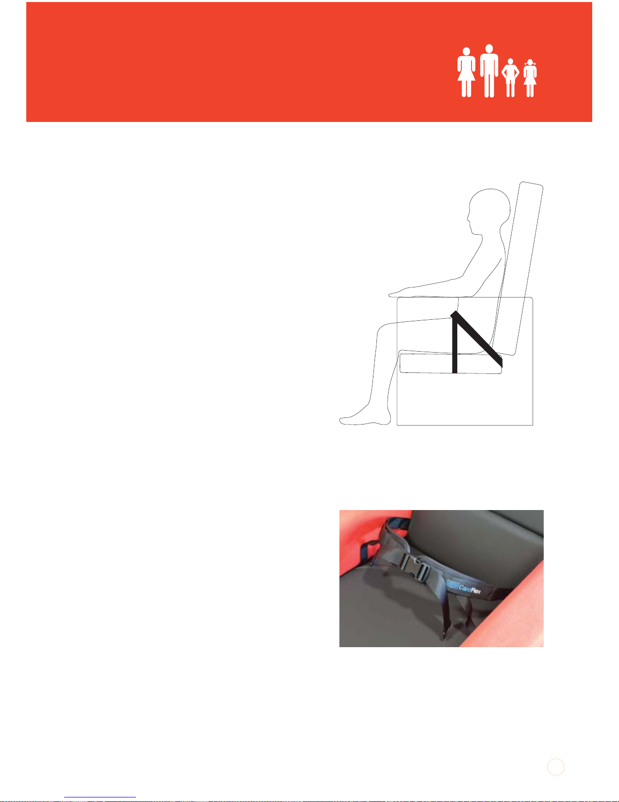
4-Point Pelvic Belt
The 4-Point Padded Pelvic belt has centre pull
adjustment. The main 40mm strap is mounted
so that it sits at between 45° and 60° across
the hips.
The secondary straps pull down over the
thighs to sit at right angles to the seat board.
The secondary straps prevent the main belt
riding up and provide some support to the
outside of the thigh. The comfort pads are
made from neoprene.
The secondary straps come down from the
main pad and over the sides of the client’s
29
4-Point Pelvic Belt with main strap coming
over the hips between 45 and 60 degrees.
Secondary strap at right-angles to seat board.
4-point pelvic strap fitted. Adjustment straps
through buckle.
Page 30
SmartSeat
®
UI SmartSeat iss01, 03/2013
TM
thighs so that they sit at right angles to the
seat board.
4-Point Pelvic Belt Set-up – Main Belt:
1. Adjust the main webbing strap through the
central side release buckle so that there is
approximately 15cm of loose webbing each
side of the buckle. Set the main length of the
belt through the tri-glide buckles on the rear
bottom edge of the back frame. The belt
should be sufficiently tight to support and
control the pelvis without being painful.
2. In day to day use clip the two halves of
the side release buckle together once the
occupant is sat in the chair. Additional tension
can be applied to the belt by pulling the D-rings
which will draw the webbing through the
buckle.
3. To open the belt, press the tabs on the sides
of the buckle so the two halves spring apart.
4-Point Pelvic Belt – Secondary Straps:
1. With the main strap correctly adjusted for
tension and position, pull the secondary straps
over the sides of the clients’ thighs and down
towards the seat board. The secondary straps
should be at right angles to the sides
of the seat board.
2. Make a note of the position of the straps
relative to the front edge of the seat. If seat
width adjustment is tending towards minimum
seat width, adjust the arms out to their widest
position. Push the sides of the seat cushion
away from the sides of the chair to reveal the
thin round bars mounted to the inside of the
chair sides.
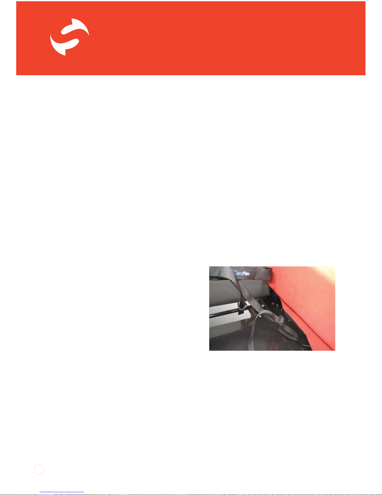
3. Thread the end of each secondary webbing
strap through a tri-glide buckle. Loop the
webbing around the thin round bars and re-
30
Front straps of 4-point pelvic strap
positioned around bars at side of seat
cushion (seat cushion removed for clarity)
Page 31
UI SmartSeat iss01, 03/2013
thread the end of the webbing through the triglide. Adjust the length of the belt by threading
more or less webbing through each tri-glide
buckle.
4. Once the tension is correct on both sets of
straps, Re-adjust seat width as per the earlier
instructions.
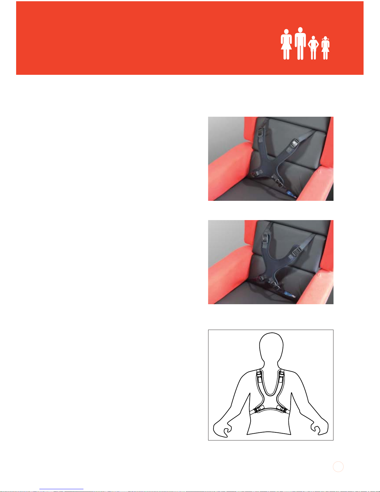
Dynamic Chest Harness
The Dynamic Chest Harness is made from
neoprene with soft edge binding which
allows the harness to stretch in response to
movement. This provides comfort and support
whilst not restricting active positioning. The
main body of the harness should be positioned
so that the bottom edge is level with the lower
edge of the rib cage. Four straps attach the
body of the harness to the chair. The lower
straps have multi-direction buckles which
swivel to follow the direction of pull to the
mounting point to avoid twisting and provide
comfort. The Dynamic Chest Harness is
designed to be used in conjunction with a
pelvic belt.
Dynamic Sternum Harness
The Dynamic Sternum Harness has the same
features as the Dynamic Chest Harness but
has a more incised profile for greater comfort
across the chest.
Adjusting the Harnesses:
Harnesses need to be positioned high up on
the chest to act against the rib cage. Ensure
the harness clears any abdominal implants.
1. Position the harness so that the bottom
edge lines up with the bottom edge of the
31
Position the harness with the lower edge level
with bottom edge of the rib cage.
Chest harness with V shaped shoulder straps
Sternum harness with U shaped shoulder
straps.
Page 32
SmartSeat
®
UI SmartSeat iss01, 03/2013
TM
client’s rib cage and the top sections of the
harness pad sit over the collar bones. This will
ensure that the webbing straps do not rub.
2. In day to day use when transferring a client
to or from the chair, undo the shoulder straps
and one of the bottom straps. The harness can
remain attached to the chair with one of the
lower buckles.
3. Regularly check and adjust the tension in the
shoulder straps by pulling the folded over end
of the webbing strap through the buckle.
4. Adjust the bottom straps at their mounting
point.
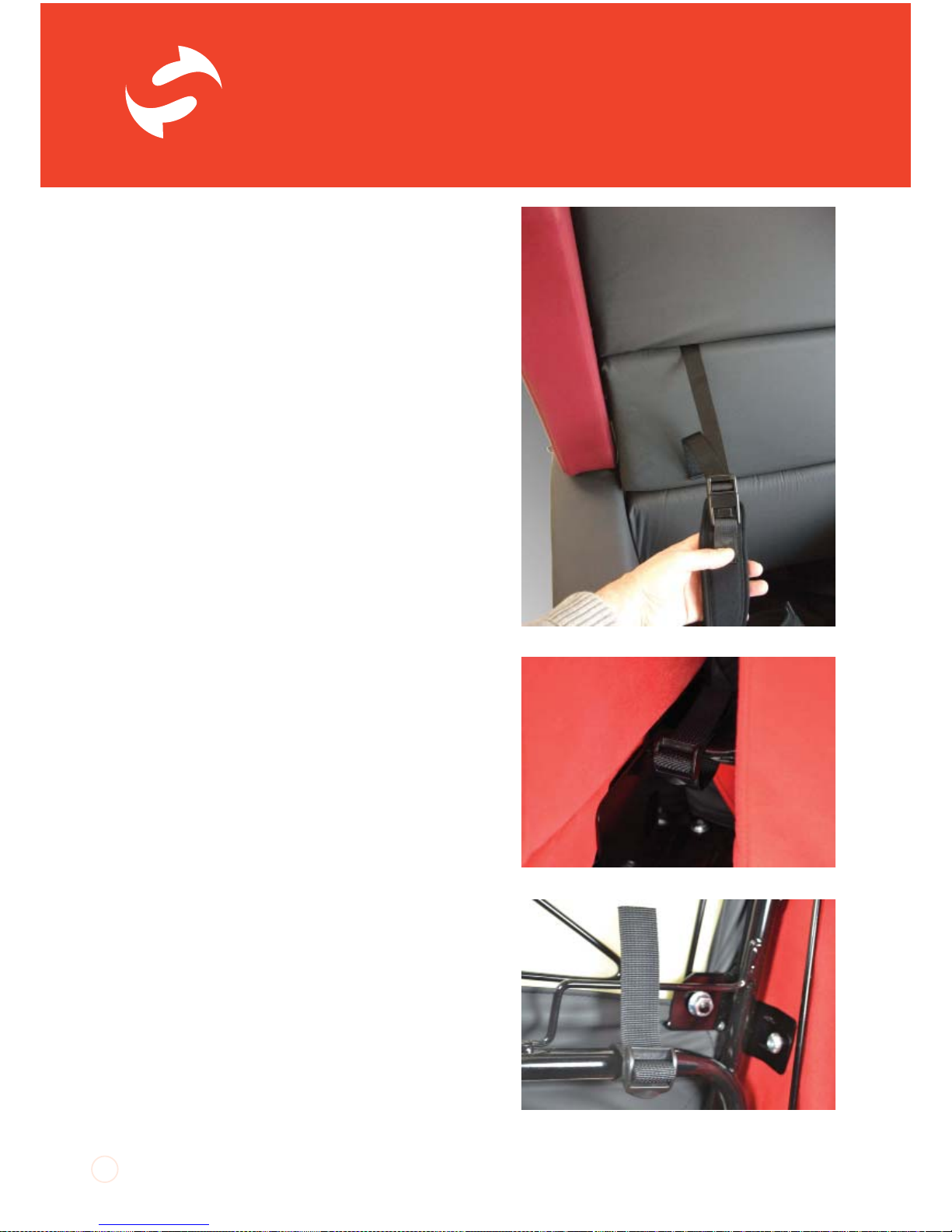
Fitting and adjusting the Straps of Chest
Harnesses:
The shoulder straps need to be fitted through
the gap between the top and middle back
cushions.
1. Unclip the rear valance. There are plastic ‘J’
strips sewn to the edges of the valance. These
clip over thin bars which make up part of the
structure of the chair back. Starting at the
lower sides, unclip the valance until it can be
folded over the top of the chair back.
2. Once the shoulder straps have been
fitted through the gap between the top and
middle back cushions a tri-glide buckle can be
threaded on to the end of each strap.
3. Each strap can then be looped around the
thin round bars on the back frame and rethreaded through the tri-glide buckle.
32
Shoulder strap adjustment
Bottom strap fitting
Shoulder strap fitting
Page 33
UI SmartSeat iss01, 03/2013
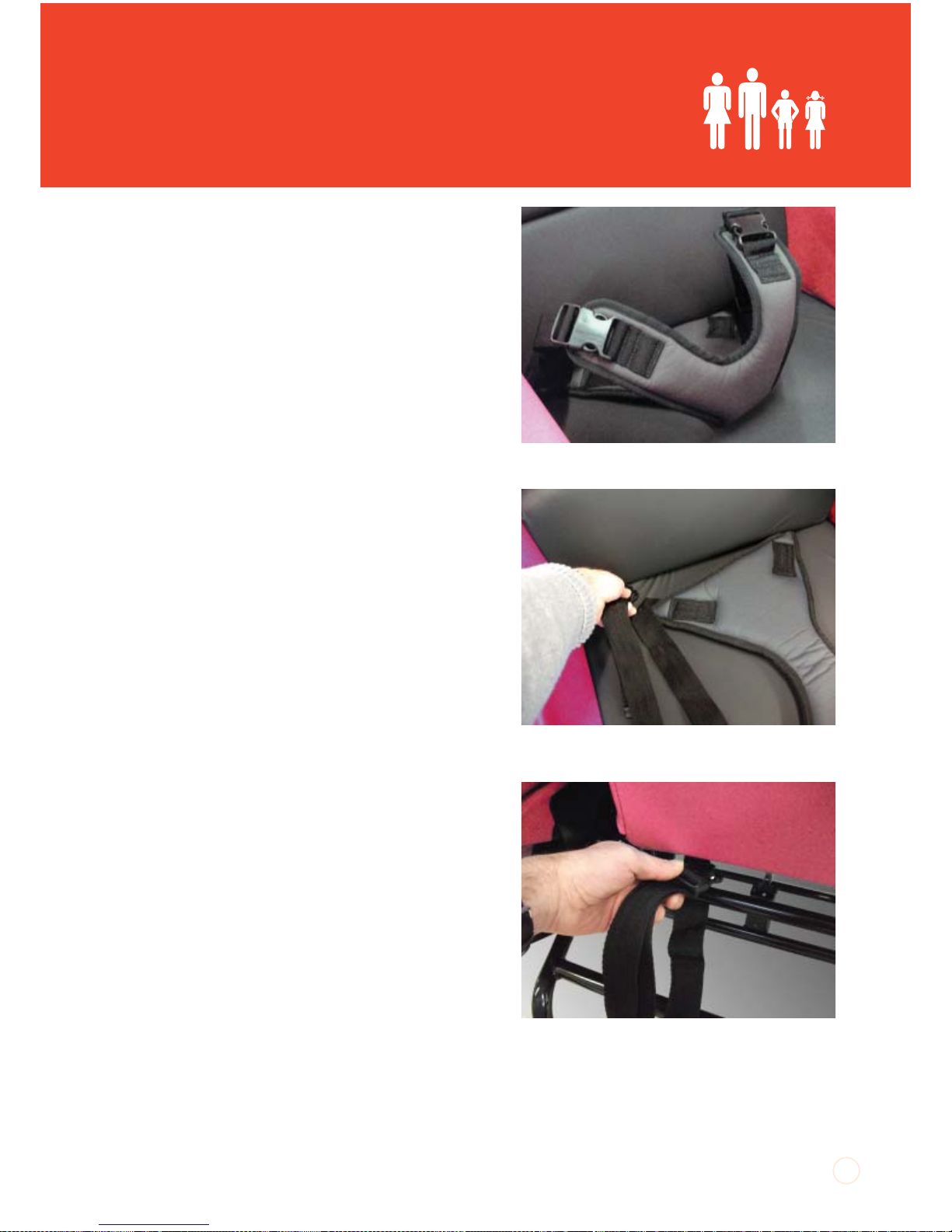
Groin Harness
A groin harness helps to keep the user
positioned correctly in the chair.
Adjusting the Groin Harness:
1. Position the loose webbing straps over the
arms of the chair and transfer the client onto
the chair so that they are sitting on the groin
harness.
2. Position the ends of the groin harness with
the buckles attached over the client’s thighs
and connect the buckles to the webbing
straps.
3. Adjust the length of the webbing straps
through the buckles so that the groin harness
helps control the client’s position.
4. Do not over-tighten the straps as this may
lead to discomfort. The groin harness must not
be used as a restraint.
Fitting the Groin Harness:
The groin harness is fitted by positioning the
harness on the seat with the buckles facing
down. The straight edge onto which the
webbing straps have been attached needs
to line up with the bottom edge of the back
cushion.
1. Push the webbing straps though the gap
between the seat and back cushions. Pull the
straps under the mounting bars on the rear
bottom edge of the back either side of the
valance. Loop the straps over the bars and
feed them back through the gap between the
seat and back cushions.
2. The straps can be positioned over the
arms of the chair until the occupant has been
transferred into the chair.
33
Groin harness
Groin harness straps fitted between seat and
back cushions...
...looped around the back frame cross bar and
fed back between seat and back cushion..
DO NOT wrap the strap around the
thin seat depth adjustment release
bar.
Page 34
SmartSeat
®
UI SmartSeat iss01, 03/2013
TM
Tr ay
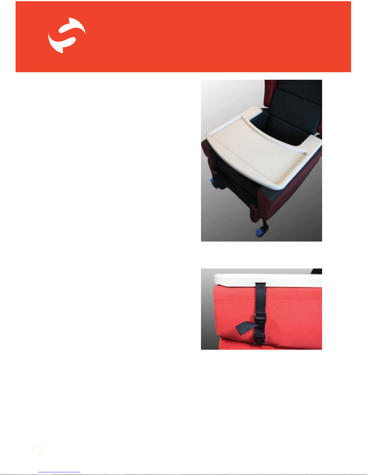
The SmartSeat chair has a tray which can be
used as a surface for activities and, when the
chair is upright, to support cups and plates.
The tray rests across the arms of the chair
and is made from moulded plastic. It has
attachment points on the sides to locate it
securely to the chair. As the SmartSeat chair’s
arms move with the seat and back as the chair
is tilted it is important that liquids and anything
else which might spill, are removed from the
tray before the chair is tilted.
As the tray can be secured in place it must not
be used as a restraint to keep the occupant in
the chair.
Using the Tray:
1. Once the occupant is sat in the chair, rest
the tray across the arms so that the tray fits
suggly against the client but does not press in
to their abdomen.
2. The buckles on the tray straps mate with the
buckles on top edge of the chair sides. Clip the
two halves of the buckles together on all four
straps.
3. Adjust the tension in the tray straps to
secure the position of the tray. The tension
can be adjusted to change the front-to-back
position of the tray.
Retro-fitting Tray Straps:
If a chair is ordered with a tray the chair will be
fitted with the appropriate attachment straps.
If a tray is ordered separately then attachment
straps will need to be fitted to the chair.
1. To do this you will need a 3mm allen key.
Begin by removing the arms of the chair as per
34
SmartSeat tray.
Tray attached and front straps adjusted to
correct tension.
Page 35
UI SmartSeat iss01, 03/2013
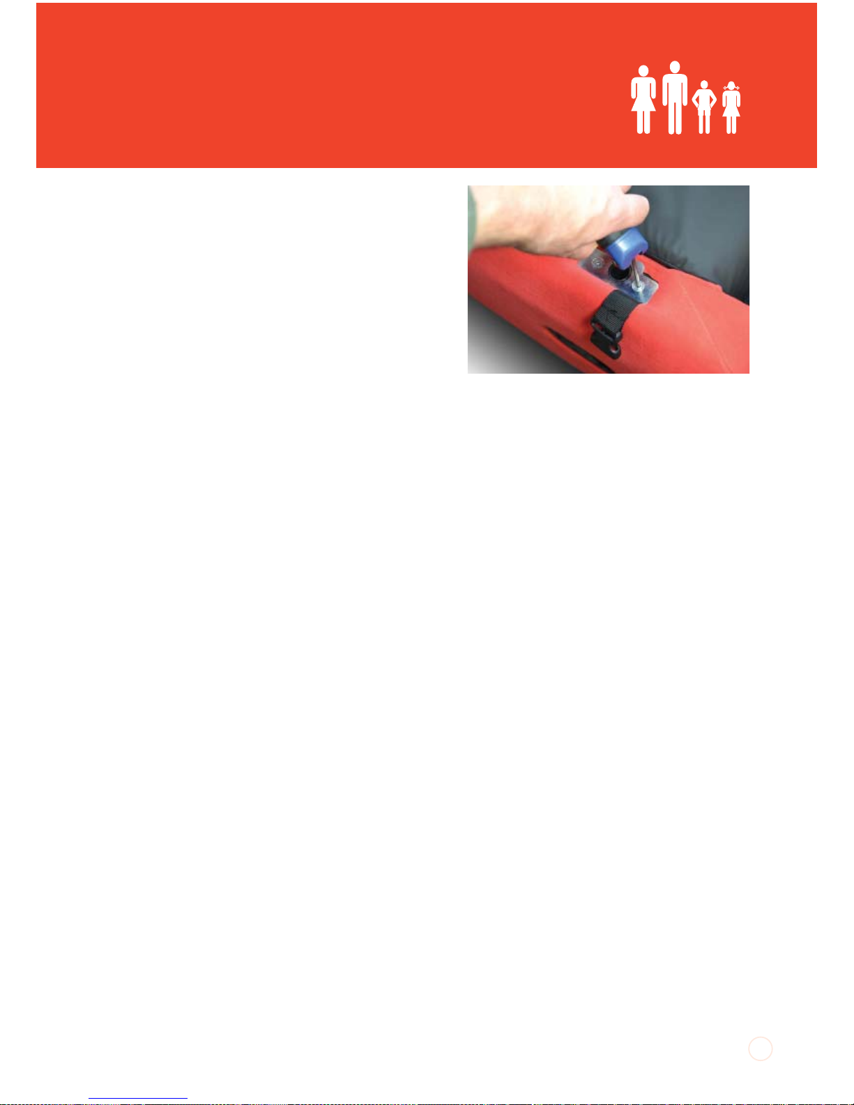
the earlier section ‘Occasional Arm Removal’.
2. With the arms removed you will see plates
surrounding the mounting points for the arm
location pegs. The plates are held in place with
counter-sunk allen screws. Use a 3mm allen
key to undo these, taking care not to drop or
loose the screws and keeping the side covers
around the mounting points in place.
3. Lift off the plates and position the webbing
straps over the front screw holes so that the
straps will hang over the sides of the base
panels.
4. Re-position the plates and screw them down
fully so that the screws pass through the plates
and webbing, captivating the straps in place.
5.
Re-fit the arms as per the earlier section of the
instructions.
35
Securing the tray straps
Page 36
SmartSeat
®
UI SmartSeat iss01, 03/2013
TM
Motorised SmartSeat
The SmartSeat uses actuators to adjust
the Tilt-in-Space and legrest elevation.
The actuators are powered by a 24V DC
rechargeable battery system which needs
to be regularly charged in order to maintain
battery performance.
Charging the Battery
When a motorised chair is first delivered and
before it is used, charge the batteries for a
minimum of 24 hours to ensure they are at
full power. Similarly, if the motors have not
been used for a prolonged period, charge
the batteries for 24 hours to bring them up
to full power. Establish a regular regime for
battery charging. Charging the chair regularly
overnight is recommended.
The battery unit will make a buzzing sound
when the battery is nearing its minimum
recommended charge level. Charge as soon
as is practicable once this signal is heard.
Avoid operating the chair when it is on charge,
especially at the beginning of a charging cycle,
as this can damage the control box.
Chargers:
1. Only chargers supplied by CareFlex should
be used to charge CareFlex chairs. Do not use
a CareFlex charger to charge other products.
2. Plug the charger in to a mains outlet with the
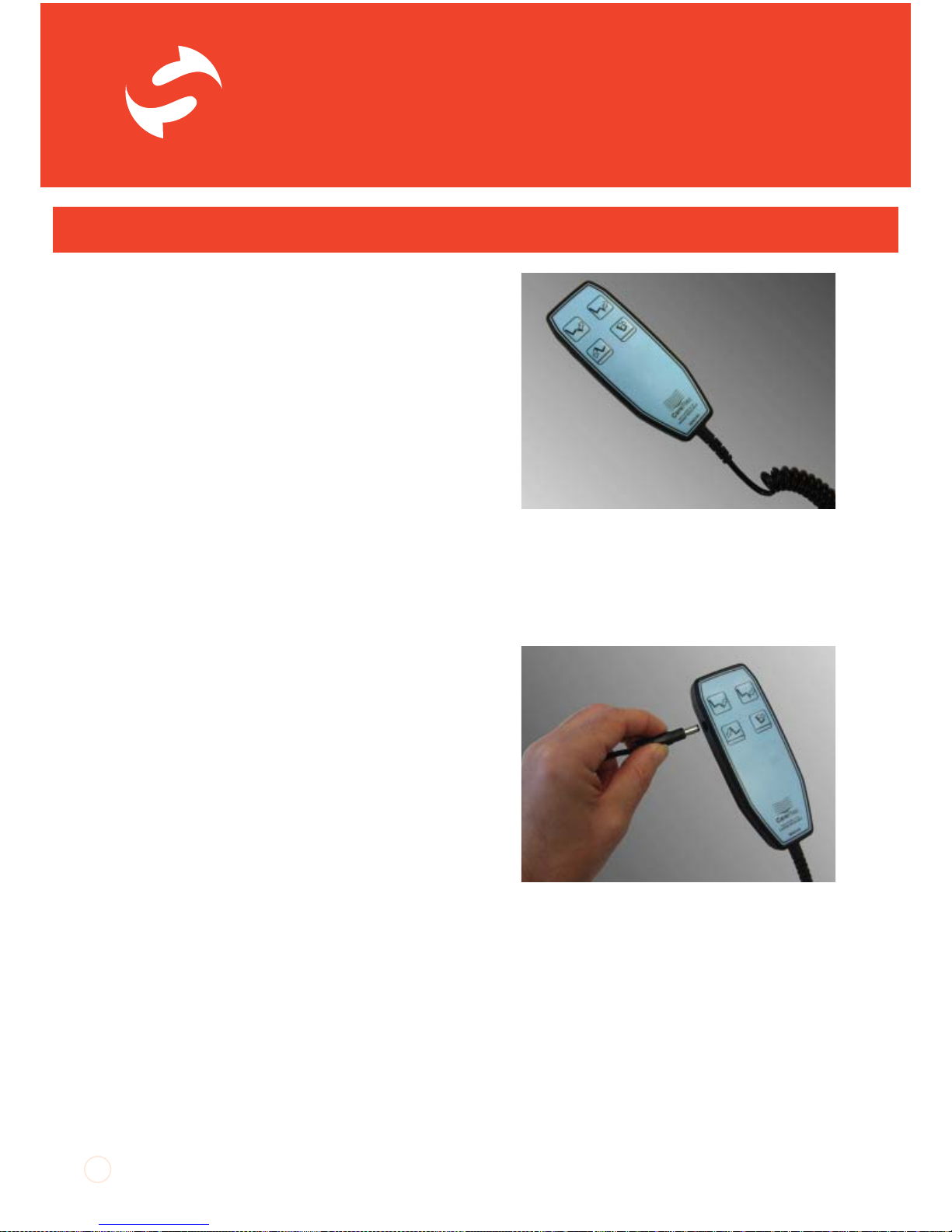
power OFF. Connect the jack on the end of the
thin charger cable to the socket on the side of
the chair handset. Switch the mains power ON.
3. The LED light on the charger should glow
yellow to indicate that it is charging. As the
batteries come up to full charge the LED will
36
Page 37

UI SmartSeat iss01, 03/2013
turn green.
4. At the end of the charging cycle, switch
the charger mains supply OFF before
disconnecting all leads and plugs.
5. When disconnecting the cable, always pull
the moulded body of the plugs straight out
of the socket. Do not pull the wire as this may
damage the cable and the socket.
DO NOT:
• Leave the chair connected to the mains with
the mains power switched off.
• Move the chair when it is connected to the
mains.
• Charge the batteries when there is a client in
the chair.
If, after charging, the motor actuators do not
work, take the chair out of service immediately
and contact CareFlex or your local Distributor.
37
Page 38
SmartSeat
®
UI SmartSeat iss01, 03/2013
TM
Looking after the chair
Care & Maintenance
Every time it is used, check the chair over for signs of damage or excessive wear. If
the chair shows signs of excessive wear, damage or incorrect performance, please
take it out of service immediately and contact CareFlex.
If the client is experiencing severe discomfort, do not use the chair. Take it out of
service immediately and contact CareFlex or your local CareFlex Distributor.
Upholstery
The chair is upholstered in high quality materials which are waterproof and fire
retardant. However, do not store or use the chair in damp or wet areas. Similarly,
do not position the chair near or against sources of direct heat or naked flames.
Covering materials may fade or degrade if subjected to excessive heat or sunlight.
Refer to the CareFlex fabric guide for upholstery cleaning details. Wipe up spills and
contamination as soon as they are noticed. Stains and soiling can lead to staining and
more severe infection control issues if not addressed immediately.
For cleaning and decontamination procedures, refer to the appropriate section
of the Fabric and Cleaning Guide supplied with the chair. CareFlex use a range
of covering materials, each with particular characteristics and specific cleaning
guidelines. If you are unsure of the chair’s covering material, contact CareFlex with
the serial number for the chair which will allow CareFlex to trace the specification of
the chair.
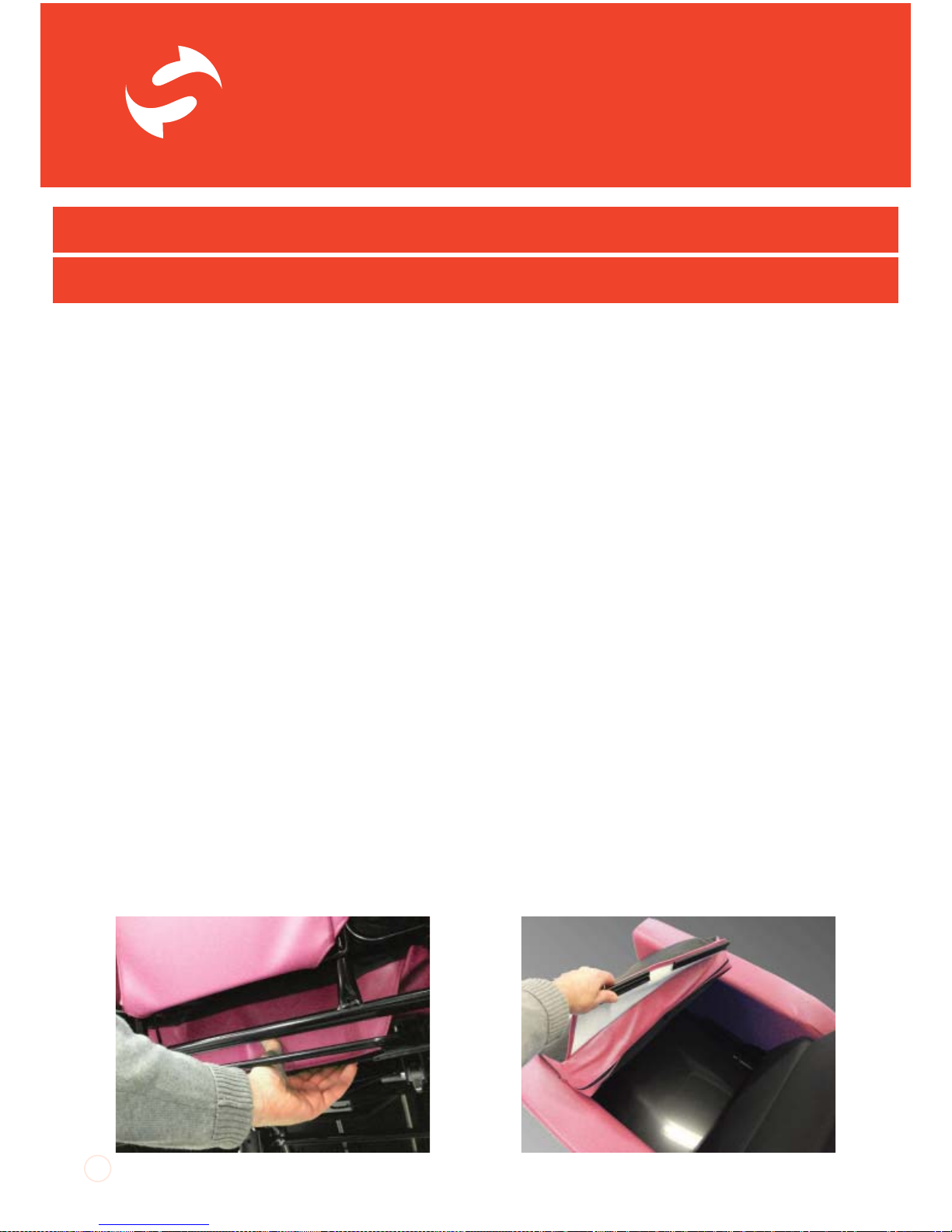
Regularly unclip the back of the seat cushion to lift the cushion up at the back and
clean the seat board and around the sides of the seat cushion where food crumbs
and other debris can accumulate.
38
Page 39

UI SmartSeat iss01, 03/2013
Structural Maintenance
Do not attempt to carry out any structural maintenance or adjustment of the chair
or its accessories without consulting CareFlex.
Motorised Chairs
For motorised chairs, regularly charge the batteries as per the earlier instructions.
Guidelines for safe operation;
• Please take the time to familiarise yourself with all the aspects of the chair and
its functions before using the chair
• Do not ‘ride’ on the push handles or subject them to excessive loads
• Do not sit on the legrest or subject it to excessive loads
• Do not attempt to stand on the footplate
• Do not tip the chair backwards to ascend steps or overcome thresholds,
especially if a client is sat in the chair
• Always ensure that the client’s feet do not drag on the ground when the chair is
moved by elevating the legrest to lift their feet off the floor
• Always ensure that there are no obstructions under the chair and that there is
plenty of space around the chair before using the Tilt-in-Space facility
• Always apply at least two brakes when the client is transferred to or from the
chair
• Always try to avoid storing or using the chair in areas where it may obstruct exits
or passageways
• The SmartSeat chair must never be used in motor vehicles for client
transportation
• Do not charge the chair’s batteries when a client is sat in the chair (motorised
versions)
• Do not move the chair if the charging lead is connected between the chair and
mains power supply (motorised versions)
39
Page 40
SmartSeat
®
UI SmartSeat iss01, 03/2013
TM
40
To fi nd out more or to book a free, no-obligation product demonstration please:
Call: 0800 0186440 | Email: enquiries@carefl ex.co.uk | Visit: www.carefl ex.co.uk
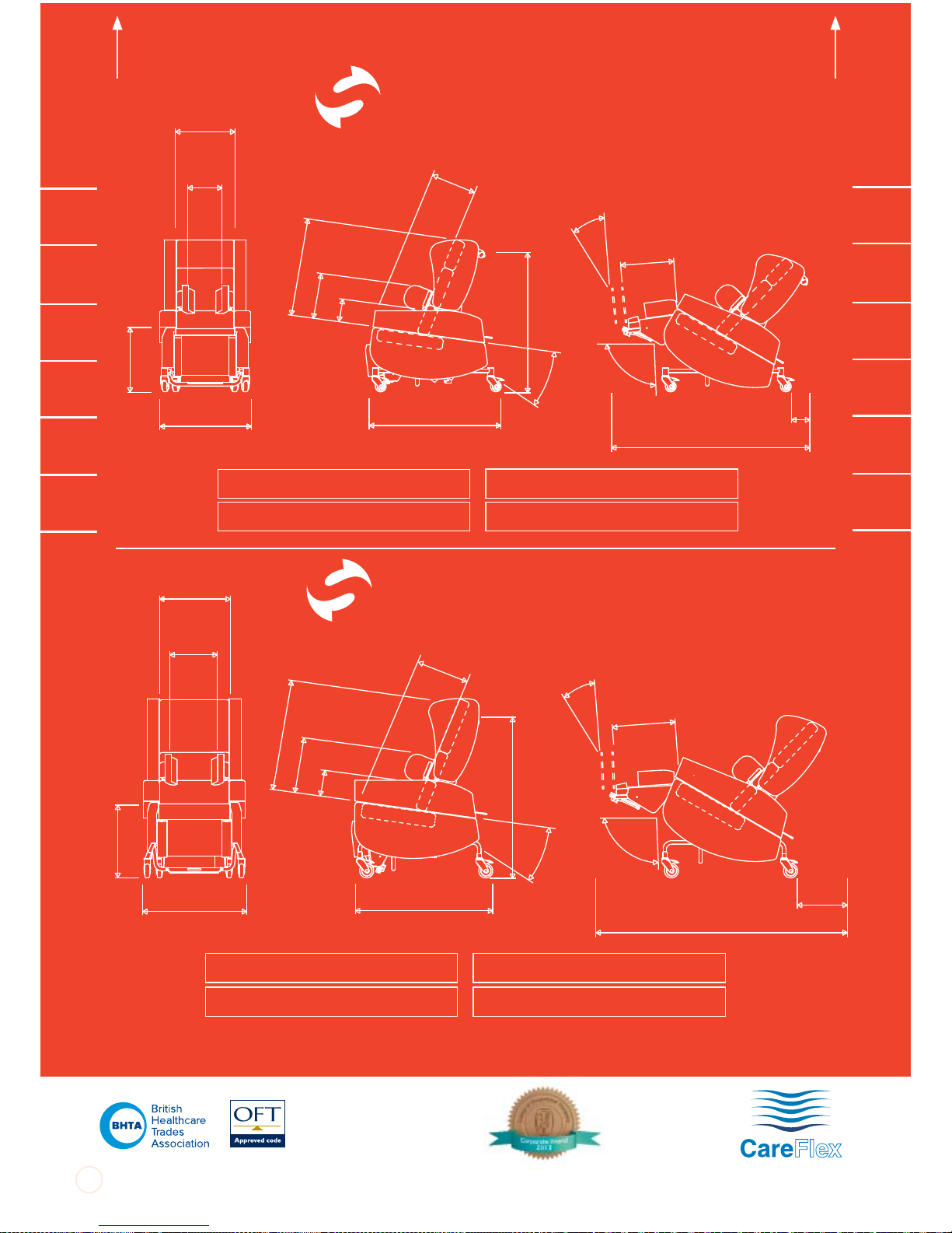
SmartSeat
®
Small
SmartSeat
®
Medium
To inside
of left arm
To inside of
right arm
38cm404244464850
38cm404244464850
Seat Width
28-40cm
Lateral
Width
13-23cm
Max Width
63cm
Seat Height
45, 48, 51cm
Push Handle
Height
93cm
Frame Length
91cm
Seat Depth
26-41cm
Back Length
70cm
Lateral Height
28-44cm
Arm Height
15cm
Range of TiS
8-30
Ankle Angle
90-120
Seat to Footplate
44-51
Max Length
164cm
TiS
clearance
21cm
Knee Angle
90-170
Max User Weight
Product Weight
100kg
60kg
Seat Width
38-50cm
Lateral
Width
23-33cm
Seat Height
49, 52, 55cm
Max Width
72cm
Back Length
86cm
Lateral Height
35-51cm
Arm Height
21cm
Seat Depth
38-53cm
Frame Length
95cm
Push Handle
Height
114cm
Range of TiS
8-30
Ankle Angle
90-120
Seat to Footplate
47-54
Knee Angle
90-170
TiS
clearance
28cm
Max Length
189cm
Max User Weight
Product Weight
160kg
70kg
 Loading...