

Page 1
UI HydroFlex. iss4 01/11 UI HydroFlex. iss4 01/11
Class 1
Medical Device
Medium = 150kg max user weight.
Small = 100kg max user weight
Care
Flex
UI
FLEXIBILITY IN A WORLD
OF MIXED ABILITY
HydroFlex User Instructions
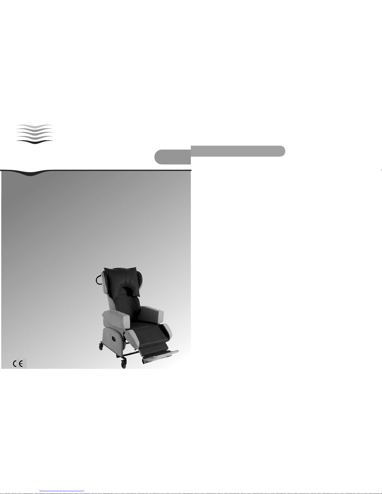
These are the user instructions for the CareFlex HydroFlex chair.
Please read them carefully before setting up and using the chair and keep them in a safe
place for future reference.
These instructions include details of the performance of the chair. If the chair should
start behaving outside of its intended performance, show signs of damage or excessive
wear, or otherwise feel unsuitable, please take it out of service and contact CareFlex
or your CareFlex Distributor immediately.
The HydroFlex chair is designed for a range of clients who require a combination
of comfort, pressure management and posture control from their seating system.
The chair has a built-in pressure management system based on CareFlex’s patented
WaterCell Technology®.
1
CareFlex classifi es the HydroFlex as an advanced seating system intended for use as part of a rehabilitation
programme. The adjustability of the chair and the range of complementary accessories means that the chair is suitable
for clients who require specifi c support and positioning to achieve a good posture.
The HydroFlex should be selected for clients;
• with neurological conditions who need to maintain a good, midline posture.
• with neurological conditions who require ‘correct’ functional positioning for rehab and activities.
• with fi xed skeletal postures of the hips and spine.
• with conditions affecting their abdomen which makes upright sitting uncomfortable.
• who require a wide range of positions for different activities through the day.
The HydroFlex chair is all about keeping the client in a good, midline position. Once set up, the position is ‘prescriptive’
and will hold the client reasonably fi rmly. For this reason, the HydroFlex is not suitable for those clients with strong
contractures or with pronounced pelvic windsweeping or obliquity. The HydroFlex is not suitable for highly agitated
clients who will not benefi t from the prescriptive support the chair offers. Unless these clients trial the chair and fi nd
it comfortable and supportive, it would be advisable to consider the softer support of the HydroTilt.
The HydroFlex is suitable for clients with neurological conditions such as MS or MND, for stroke rehabilitation and
rehabilitation following spinal or head injury.
The HydroFlex incorporates features which allow it to be set up to accommodate different postures and provide seating
positions for a range of activities. The key features are;
• Tilt-in-Space, which allows the clients position to be adjusted without affecting pelvic position.
• Back Angle Recline, which can be adjusted to provide a comfortable hip angle.
• Legrest elevation, to raise the legs and support the lower leg with the knees at a relaxed angle.
The suitability and effectiveness of these features are dependent on correct chair set up. Correct chair set up is
dependent on three key elements; seat to fl oor/footrest height, seat width and seat depth.
Seat to fl oor height and seat width will have been measured during the initial seating assessment and the HydroFlex
will have been factory assembled to these measurements. Seat depth must be adjusted to suit the client once the
chair has been delivered. Seat to footplate height can be adjusted to suit the client.
Use a cloth tape measure to measure the client as you are setting up the chair. This will help limit the need for
any re-adjustment.
Regularly check the HydroFlex set up to ensure it is working as intended and the client is benefi ting from the pressure
management solutions which are built into the chair.
HydroFlex Client Characteristics
2
Page 2
UI HydroFlex. iss4 01/11 UI HydroFlex. iss4 01/11
Fixed and Loose Covers
Pressure Management
The HydroFlex incorporates CareFlex’s patented WaterCell Technology® in the seat in combination with a composite
visco elastic memory foam and high elastic foam cushion. The memory foam allows the seat cushion to conform
to the client’s body shape, distributing their weight over as large a surface area as possible. The high elastic foam
prevents the memory foam bottoming out and makes the cushion responsive to client movement. The WaterCell
Technology moves with the client to ensure that the cushion remains in contact with the client as they move and
alter their weight distribution.
Two lumbar options are available for the HydroFlex and each provides pressure relief in a different way. The deep
laterally contoured back has kidney pads to provide simple lateral stability. These pads also increase the contact
surface between client and seat, distributing their weight over as large a surface area as possible. The fl at back
incorporates a water cell which covers the lumbar and kyphotic spine.
These pressure relief features make the HydroFlex suitable for those clients at medium to high risk of pressure damage
when used as part of a therapy programme assessed and prescribed by an appropriate Healthcare Professional.
Adjustment Control Options
There are three formats of the HydroFlex available, manual, motorised and Pro-control. On the manual version of the
HydroFlex Tilt-in-Space, Back Angle Recline and the elevating legrest are controlled by locking gas actions.
On the motorised version of the HydroFlex the Tilt-in-Space, Back Angle Recline and the elevating legrest are controlled
by electric actuators which are powered by a rechargeable 24V battery system.
The Pro-Control version of the HydroFlex uses actuators to control the Tilt-in-Space and legrest features but utilizes
a locking gas action for the back angle recline. This is because in many situations the back angle recline needs to
be set up at a specifi c angle for the client and should not be adjusted further. The Pro-Control system allows the
healthcare professional to set up the back angle recline and leave the day to day adjustments of TiS and legrest
elevation to the client/carer.
Identifi cation
Each HydroFlex chair has a unique chair number which must be quoted during any correspondence with CareFlex or
your local CareFlex Distributor. This number is on a silver foil label on the cross bar of the seat depth adjustment
frame at the back of the chair. The number is essential for tracing the product and allows accessories and spare
parts to be easily selected.
3
The HydroFlex is available with either fi xed or loose covers. The fi xed cover version has a cleaner, crisper appearance
to make what is essentially a clinical product look more appropriate in a domestic environment. The fi xed cover
greatly reduces the need for Velcro on the chair, which may make the chair more appropriate in areas where infection
control is a signifi cant consideration. The loose cover version has greater fl exibility in terms of adjusting the chair’s
confi guration and carrying out servicing and repair procedures.
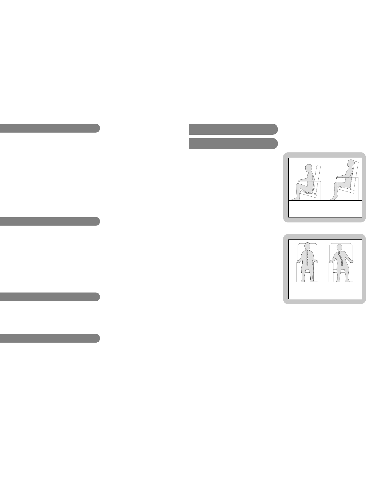
Correct seat width; client
sits ‘midline’.
Seat Too Wide; client tends
to lean to one side.
1. Chair Set-up
1a. Seat Height & Width
Seat Too Low;
Increase in pressure on the
buttocks and lower back.
Seat Too High;
Increase in pressure
beneath thighs.
If the client can raise to standing themselves or with
minimal assistance, the seat height should be set so that
the client’s feet rest fl at on the fl oor and the underside
of their thighs are in contact with the full length of the
seat cushion. If the seat height is too high, the client’s
heels will be lifted off the fl oor and pressure will build
up along the underside of their thighs. If the seat is
too low, their knees will be raised and there will be no
contact between the back of their thighs and the seat
cushion. This will increase the pressure on their bottom
and sacrum and could cause discomfort at the hips.
If the client is less ambulant and is being regularly
portered then seat height can be set relative to the
footplate. Again, ensuring the foot is fl at and fully
supported is important.
Seat width affects side-to-side pelvic stability. This is
important as the spine should line up centrally with the
pelvis. If the pelvis is free to move to one side then the
client’s spine will usually lean in the opposite direction. As
gravity pulls the client over, the spine will begin to curve
to compensate as the client tries to keep their head level.
The client will take on a characteristic ‘S’ shaped spine or
scoliosis. The more upright the user’s trunk is, the more
critical pelvic stability becomes. It is, therefore, important
to use a chair with the correct seat width in order to
position the pelvis properly.
Seat width should always allow for a little bit of movement
as the client’s body weight and posture naturally shifts
throughout the day. If the client is held in a rigid
position they will quickly tire and experience discomfort.
HydroFlex seat height and width will have been measured during assessment and the chair made to these
dimesions for the client prior to delivery.
If further adjustment is required, please contact your
local CareFlex Distributor.
4
Page 3
UI HydroFlex. iss4 01/11 UI HydroFlex. iss4 01/11
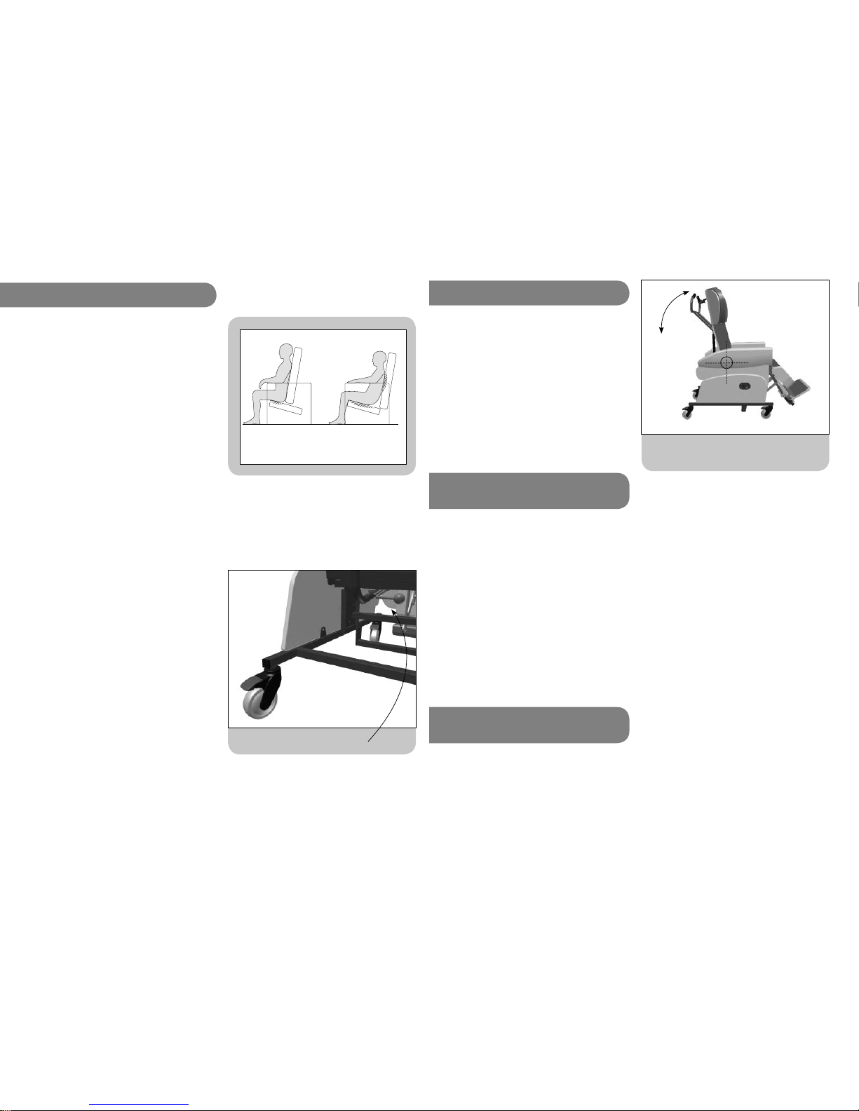
Seat Too Short;
Increase in pressure
beneath the bottom.
Seat Too Long;
Increased pressure on bottom,
sacrum and shoulders.
1b. Seat Depth
It is important to set seat depth correctly in order to
prevent ‘sacral sitting’ and to achieve the best distribution
of weight between the client and the chair. Sacral sitting
occurs when the pelvis tilts backwards so that the lower
back (sacrum), as well as the bottom, is resting on
the seat cushion. The sacral area can be susceptible to
pressure problems. Sacral sitting will occur if the seat
depth is too long. If the seat depth is too short then
the client’s body weight will be concentrated in too small
an area.
Seat depth should be set with the client’s bottom
positioned fi rmly at the back of the seat cushion so
that their lower back and lumbar is supported by the
back cushion. There needs to be a two or three fi nger
gap between the client’s calf and the front of the seat
cushion for comfort.
If the client already has a chair or wheelchair with the
correct seat depth, measure this size and use it to set
up the HydroFlex.
Seat depth is adjusted by moving the back of the chair
over the seat unit. The front edge of the seat will stay in
the same place. The seat depth mechanism is controlled
by a release lever on the rear left hand underside of
the seat.
To adjust seat depth, twist the seat depth release lever
clockwise. Hold one of the curved tubes of the seat back
frame and push/pull the back to the desired position.
Once the back is in the correct position let go of the
lever. The back may ‘jump’ back slightly as the locking
mechanism engages.
Release lever for adjusting seat depth.
Seat depth should not be
adjusted when a client is sat in
the chair or when the chair is
tilted backwards.
5
1c. Back Angle Recline
Back Angle Recline (BAR), where hip angle can be
adjusted.
The HydroFlex has Back Angle Recline (BAR). BAR is used
to adjust the angle between the seat and back, thus
changing the angle of the client’s hips.
When the back is fully upright, the angle at the client’s
hips will be approximately 95°. However, because of the
contoured profi le of the back, the client will fi nd this
a comfortable position for mealtimes, activities and for
preparing to raise to standing.
The back angle can be reclined to give a 125° angle at
the hips. This is a comfortable position for resting.
1d. Back Angle Recline
Adjustment
Caution has to be taken when adjusting BAR to provide
a comfortable and stable sitting position. If misused, BAR
can lead to an unstable seating position where the client
can easily slide out of the chair or quickly slide into
sacral sitting. Both sliding actions could lead to pressure
damage through shear.
Ideally, BAR should be altered very occasionally to suit
client condition. For regular changes of position it is best
to use the TiS facility, as this can be adjusted without
affecting pelvic stability. BAR may be disconcerting for
some clients. Please ensure the client is comfortable and
does not become distressed if they are fully reclined
backwards.
1e. Back Angle Recline
Fully Motorised Version
On the motorised HydroFlex BAR is controlled by the
handset. The third row of two buttons control BAR. The
right hand button reclines the back. The left hand button
returns the back to its upright position.
6
Always warn the client before
changing back angle to ensure
they do not become distressed
or agitated.
Page 4
UI HydroFlex. iss4 01/11 UI HydroFlex. iss4 01/11
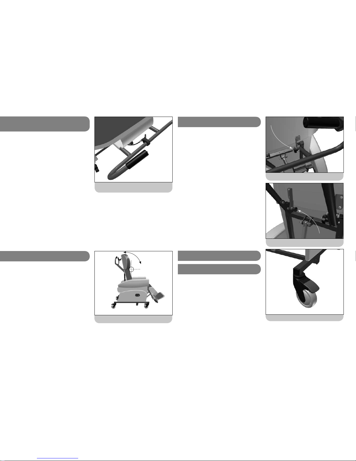
BAR lever hidden under push bar valance.
1f. Back Angle Recline
Manual & Pro-control
A small lever located on the centre of the push bar
controls Back Angle Recline. This lever is hidden by a
valance cover to prevent the BAR being accidentally
activated. As mentioned above, BAR has a fundamental
affect on seating position and must only be adjusted by
those who understand how to achieve a good sitting
posture.
To adjust the back angle recline, undo the valance from
the underside of the push bar to reveal the small BAR
lever. Squeeze the lever gently to unlock the gas action
controlling BAR and allow the back to be tilted to the
required angle. When the client is in a comfortable
position, let go of the lever and the back angle will
lock in position. Re-position the valance cover to hide
the BAR lever.
7
1g. Articulating Back
The Articulating Back allows for profi ling of the back
to accommodate kyphosis and more complex head
positioning issues. The top section of the chair back can
be angled through a range of 35° forward of its upright
position in 5 indexed steps.
Leg Elevation, where knee angle can be adjusted.
3. Day to Day Use
3a. Brakes
Brake lever on rear castor.
Before transferring in and out of the chair the brakes on
the castors should be activated. The castors have a full
brake which locks roll and swivel. Always ensure that at
least two of the castor brakes are applied before a client
transfers in or out of the chair.
To apply the brakes begin by generally positioning the
chair. Once the chair is in the desired position push it
forward slightly. This will swing the rear castors around
to reveal the brake levers. Press down the end of the
levers to lock the brakes. To release the brakes, gently
kick the top of the brake lever so that it clicks fl at.
Do not attempt to push the
chair with the brakes applied as
this can damage the castors and
stress the frame of the chair.
8
Undo the locking wheel fi rst...
There is a two stage adjustment to the Articualting
Back mechanism. Firstly, the locking wheel needs to be
released. This is located on the right side of the back
frame where the push bar is attached to the back frame.
Turn the locking wheel through two complete turns to
free the mechanism.
The second stage is to pull out the indexing pin on
the left side of the back frame. The top section of the
back can now be angled. Once in position to support
the client’s head and shoulders, release the indexing pin
and feel for it clicking into place. Re-tighten the locking
wheel to eliminate any wobble in the mechanism.
1g. Articulating Back
...& pull out the indexer on the left to adjust angle.
Page 5
UI HydroFlex. iss4 01/11 UI HydroFlex. iss4 01/11
3d. Motorised & Pro-control
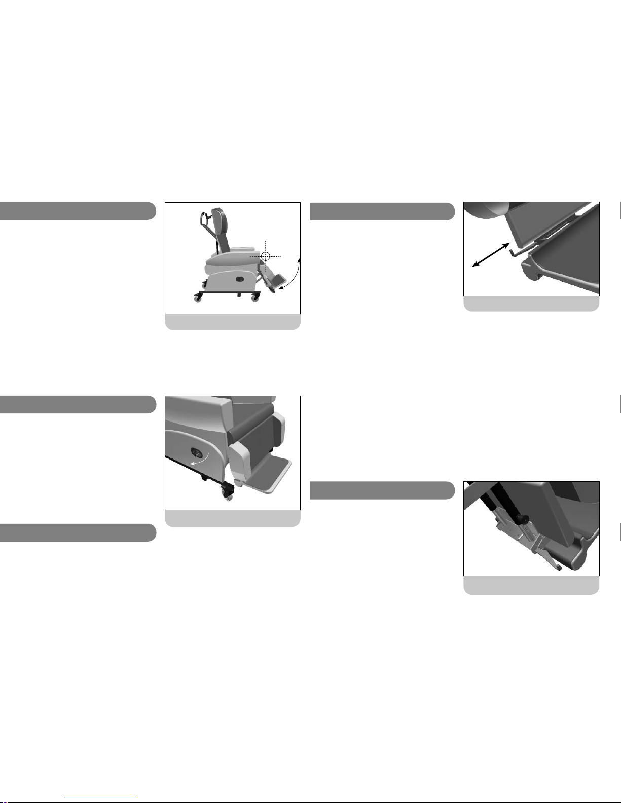
Release lever for legrest elevation.
3c. Manual Option
3b. Elevating Legrest
The HydroFlex has an integral legrest which can be
angled up to support the legs. The legrest articulates,
following the movement of the knee as it elevates the
legs.
The legrest incorporates visco-elastic memory foam for
pressure relief.
Ensure the legrest is fully lowered before transferring a
client to or from the chair.
The range of Legrest elevation is from 80° at the
knees to 170°. The comfort of legrest elevation is often
determined by hip angle. Over-elevating the legs can
cause tightness in the hamstrings which could cause
discomfort, especially if the BAR has been set up so that
the hip angle is close to 90 degrees.
Leg Elevation, where knee angle can be adjusted.
On the manual option of the HydroFlex legrest elevation
is controlled by the lever located on the right hand side
panel. Pull this lever out and the legrest will begin to
raise. It may be necessary to lift the legrest towards
its maximum elevation, depending on the weight of the
client’s lower legs. Once the legrest is at the desired
angle, release the lever. To lower the legrest, pull the lever
out and the legrest will return to its lowered position. It
may be necessary to push the legrest down if the client
has weak or light lower legs.
On the motorised and Pro-control options, legrest
elevation is controlled by the handset. The top row
of two buttons control Legrest elevation. The left hand
button raises the legrest. The right hand button returns
the legrest to its lowered position.
9
3d. Integral Footplate (cont.)
Pull the lever sideways to adjust footplate angle.
The legrest has an integral height and angle adjustable
footplate to provide support to the client’s feet when
the legrest is raised or when they are being portered in
the chair. The footplate is stored behind the top section
of the legrest. Lift the top section of the legrest and
the footplate will drop dow. To lock the footplate in its
primary, 90° angle, pull the lever on the right side of
the footplate sideways. The footplate has three angle
settings to provide comfort and support plantarfl exion.
As the legrest is elevated, having a 90° angle at the
ankle will become more uncomfortable. The footplate can
be angled down to provide a more relaxed position. To
adjust the angle pull the lever on the right side of the
footplate sideways. Tilt the footplate to the desired angle
and release the lever. The lever will slide into the nearest
angle setting.
To fold the footplate up and store it behind the top
section of the legrest, pull the lever on the right side
of the footplate sideways and raise the footplate up. Lift
the top section of the legrest, push the footplate fully up
and lower the top of the legrest to hold the footplate
in place.
SAFETY NOTE
It is essential to regularly check
the adjustment of the footplate
to ensure it does not hit the
ground when lowered. When
the chair is tilted backwards it
is possible to extend the legrest
length so that it is greater than
the seat to fl oor height. However,
if the chair is tilted forward when
the legrest is fully extended the
footplate may hit the fl oor and
damage the legrest mechanism.
3e. Seat to Footplate Height
Indexing pin to set the seat to footplate height.
Seat to footplate height can be adjusted by pulling out
the indexing pin located on the (client’s) right hand side
of the legrest assembly. Pull out the indexer and raise/
lower the footplate to the desired height relative to the
seat. Once at the desired height, release the indexer. The
indexer will click into the nearest height setting and lock
the footplate height.
10
Page 6
UI HydroFlex. iss4 01/11 UI HydroFlex. iss4 01/11
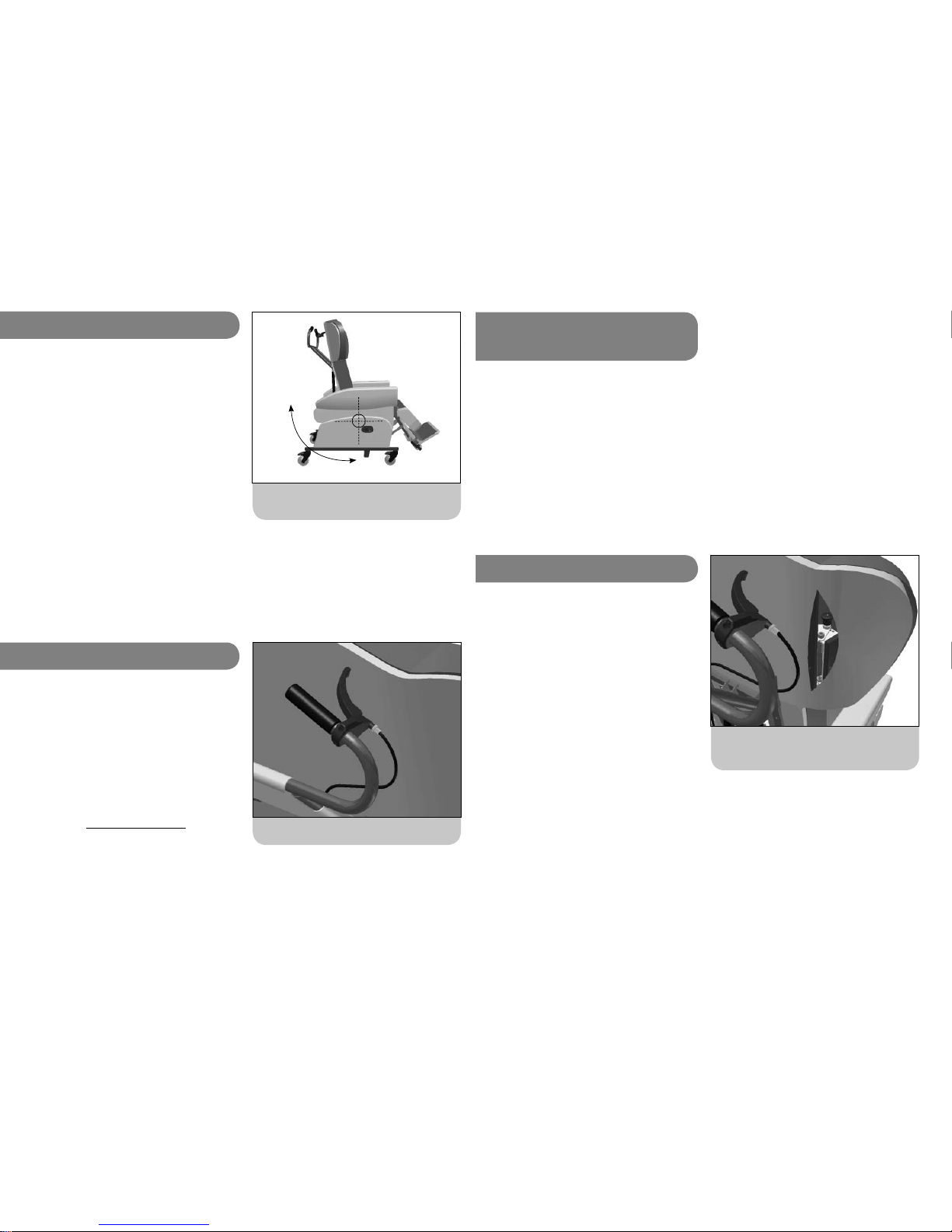
Tilt-in-Space lever, manual HydroFlex.
3f. Tilt-in-Space (TiS)
Tilt-in-Space, where seat to back relationship stays
the same as the chair tilts.
The HydroFlex has a Tilt-in-Space facility which allows
the client to be reclined without adjusting the angle at
the hips.
This helps the client to maintain a stable sitting posture
whilst distributing their weight over a large surface area.
Tilt-in-Space should be regularly adjusted to facilitate an
easy change in weight distribution, thus avoiding pressure
build up in any one area.
Always warn the client before changing Tilt-in-Space to
ensure they do not become distressed or agitated.
The chair will Tilt-in-Space 30° backwards. This degree of
tilt may be disconcerting for some clients. Please ensure
the client is comfortable and does not become distressed
if they are fully tilted backwards.
3g. Tilt-in-Space Manual Option
On the manual option the TiS feature is controlled by the
large lever on the push handle.
To adjust the TiS, squeeze the lever and tilt the chair to
the desired angle. Release the lever to hold the chair at
the desired angle.
SAFETY NOTE
When tilting the HydroFlex
forward, ensure the footplate
height is set so that the footplate
will not hit the fl oor.
11
3h. Tilt-in-Space,
Fully Motorised and Pro-control
Open the sides of the back cover to reveal the
indexer for wing angle adjustment.
On the motorised and Pro-control option the Tilt-in-Space
is controlled by the handset. The second row of buttons
control Tilt-in-Space. The right hand button tilts the
chair back. The left hand button returns the chair to its
upright position.
NOTE: The HydroFlex has a large range of Tilt-in-Space.
When the chair is fully upright, the seat surface will
be level with the fl oor, encouraging the client into a
standing position.
3i. Back Wings
The top section of the HydroFlex back has adjustable
wings to help upper trunk positioning. The wings are
angle adjustable and can be used to help stabilise
headrest position, provide support to the shoulders or
change the shape and support offered by the soft pillow
headrest accessories.
The wings can be angled in to provide close support for
the client or opened out if the client is broad across the
shoulders or does not want to feel restricted.
To adjust wing angle, open the zip closures at the top
of each side of the back cover. A small recess houses an
indexing pin controlling wing angle. Lift the top of the
indexing pin to release the wings and adjust them to
the desired angle. Once at the desired angle, release the
index and allow the pin to lock into the nearest setting.
After adjusting wing angle, fasten the velcro closure so
that the cover sits neatly.
12
Page 7
UI HydroFlex. iss4 01/11 UI HydroFlex. iss4 01/11
4a. Batteries and Charging
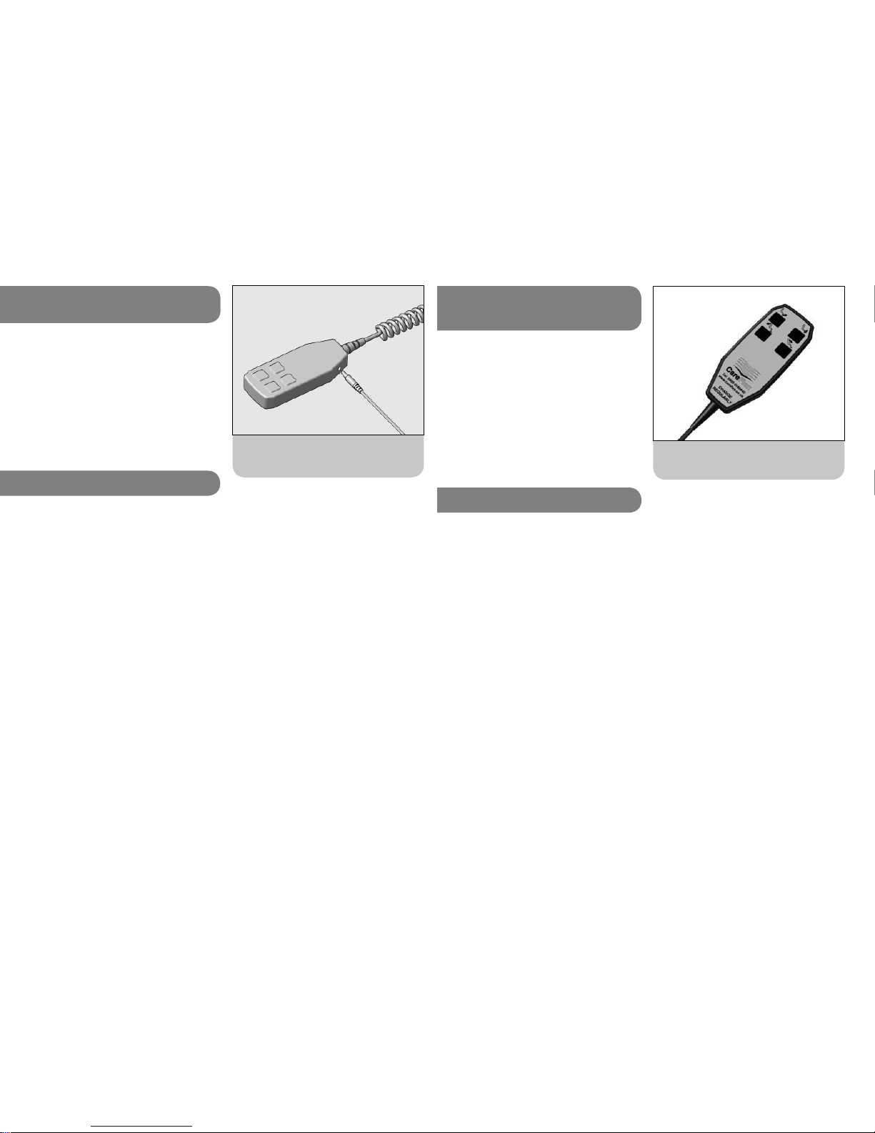
Plugging the charger jack into the socket on the
side of the handset.
4. Fully Motorised &
Pro-Control Chairs
The Pro-Control HydroFlex uses actuators to adjust the
Tilt in Space and legrest elevation. The fully motorised
HydroFlex uses actuators to adjust the Tilt in Space,
Legrest elevation and Back Angle recline. Both systems
utilize a 24V DC rechargeable battery system which needs
to be regularly charged in order to maintain battery
performance.
When a motorised chair is fi rst delivered and before it
is used, charge the batteries for twelve hours to ensure
they are at full power. Similarly, if the motors have not
been used for a prolonged period, charge the batteries
for twelve hours to bring them up to full power. Establish
a regular regime for battery charging. Charging the chair
regularly overnight is recommended. The battery unit will
sound a warning signal when the battery is nearing its
minimum recommended charge level. Charge as soon as
is practicable once this signal is heard.
Only chargers supplied by CareFlex should be used to
charge CareFlex chairs. Do not use a CareFlex charger to
charge other products.
• Fit the jack plug connected to the charger into the
socket on the hand control unit of the chair.
• Plug the charger into a 240V AC mains electric
supply and switch on the power to the charger. See
the notes above for charge times.
• At the end of the charging cycle, switch off the
charger and disconnect all leads and plugs.
When disconnecting the cable, always pull the moulded
body of the plugs straight out of the socket. Do not
pull the wire as this may damage the cable and the
socket.
DO NOT:
• leave the chair connected to
the mains with the mains power
switched off.
• move the chair when it is
connected to the mains.
• charge the batteries when there
is a client in the chair.
If, after charging, the motor
actuators do not work, take the
chair out of service immediately
and contact CareFlex or your local
Distributor.
NOTE: AutoTilt chairs have a different location for attaching the charger.
See the AutoTilt section for details.
13
Handset for Pro-Control HydroFlex.
4b. Using a Chair with Motorised
Actuation
A chair with motorised actuation has a hand controller
on a coiled fl ex attached to the control box on the chair.
To activate the actuators and tilt the chair, elevate the
legrest or recline the back, depress the appropriate up or
down button for the facility required.
Always warn the client before
making any adjustment to the chair
so that they do not become agitated
or confused.
4c. AutoTilt Facility
The Pro-Control and fully motorised HydroFlex chairs
are available with an AutoTilt facility. This has been
developed to enhance the pressure management already
found in the HydroFlex and to make more effi cient use
of the nursing care and time needed to achieve good
pressure care.
The AutoTilt reduces the amount of carer input by
automatically adjusting the chair at timed intervals. Every
45 seconds micro-processors move the HydroFlex through
0.5° of Tilt-in-Space in order to continually re-focus the
pressure points on the body. The AutoTilt starts at any
position through the tilt cycle. Once activated the chair
will tilt backwards to the maximum tilt position before
tilting forwards to approximately halfway through the tilt
cycle. The chair will not come fully upright during the
AutoTilt cycle but will change direction to tilt backwards
from the halfway point. A full AutoTilt cycle lasts 16
minutes.
The AutoTilt will repeat this cycle for either one or eight
hours, ensuring optimal pressure care for those that
need it most.
14
Page 8
UI HydroFlex. iss4 01/11 UI HydroFlex. iss4 01/11
4d. AutoTilt in Use
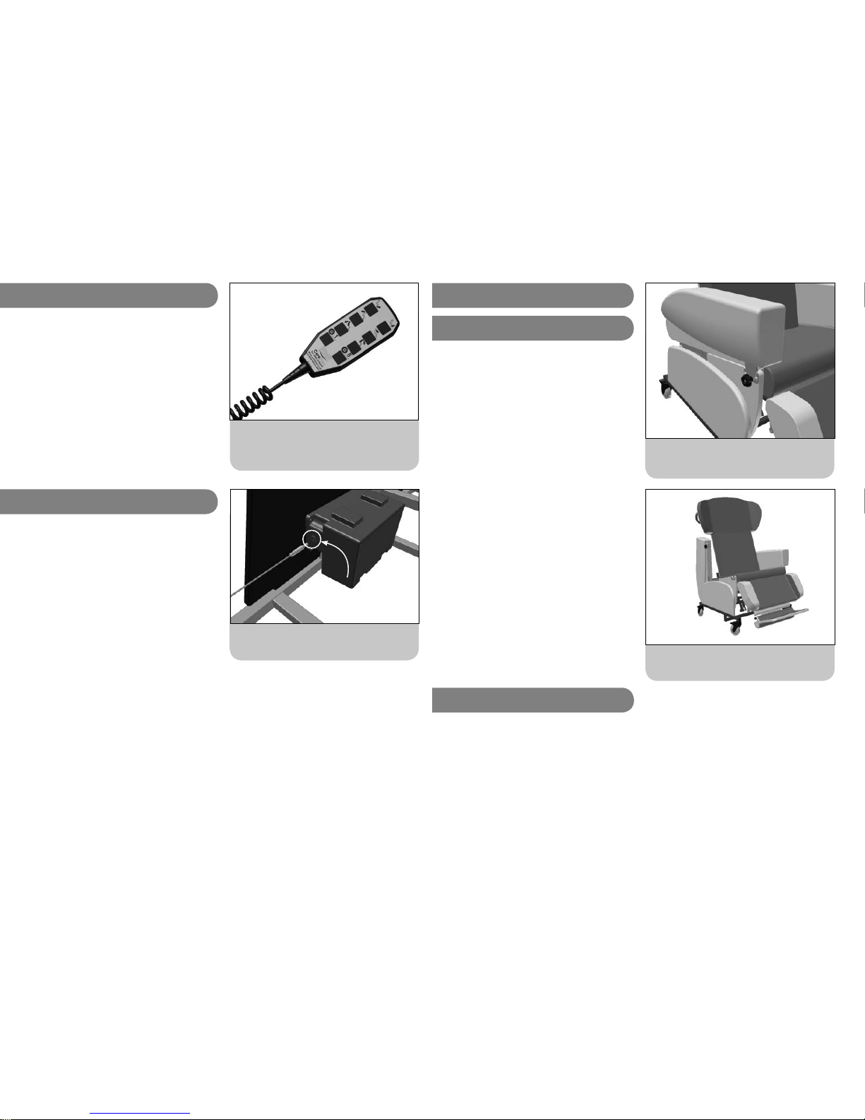
AutoTilt chairs are fi tted with an eight button handset.
For Pro-Control versions, the buttons indicating Back
Angle Recline adjustment (3rd row) do not function.
By depressing the bottom left button the one hour
AutoTilt cycle will begin. Pressing the bottom right button
activates the eight hour cycle. If the chair is fully upright
it will begin to tilt backwards at the intervals described
above.
Pressing any of the function buttons on the handset will
interrupt and stop the AutoTilt cycle.
The HydroFlex AutoTilt control box is charged directly
from the supplied 24V charger. There is a small jack
socket on the back edge of the control box where the
supplied 24V charger needs to be fi tted.
The control box has a safety cut out to stop the batteries
being fully discharged. Once the working load voltage
drops below 21V the unit will not work. Put the chair
on charge for twelve hours and do not operate the chair
when it is on charge.
The TiS motor makes a small beeping noise when it
moves. This is a harmonic resonance caused by the soft
start program used to reduce the amount of ‘bounce’ in
the movement of the AutoTilt.
The control box has been programmed to ‘back off ’ at
the minimum and maximum strokes of the motors and
if the motors sense an overload, e.g. if the legrest was
elevated against a wall. If the motors automatically ‘back
off’, release the button being depressed on the handset
and press the opposing button to re-set the unit.
4e. AutoTilt Battery Charging
Connect the charger to the socket on the back
edge of the AutoTilt control box.
8 button handset for all HydroFlex AutoTilt chairs.
NB: 3rd row of buttons are not used on ProControl chairs.
15
Transfer arm tilted back to give access for side
transfer.
Undo the locking wheel to release the transfer arm.
5. Options and Accessories
5a. Transfer Arm
The transfer arm option makes side transfer easier, either
from a bed or wheelchair. The arm can be tilted up and
back to give clear access to the seat.
The transfer arm should only be used when the seat is
fully upright. A locking wheel beneath the front outside
edge of the arm cushion locks the transfer arm in place.
Undo the wheel by a couple of turns and lift the arm up
from the front. As soon as the front of the arm lifts up
it can be slid back and pivoted so that it hangs down
at the back of the chair.
Once the client has transferred to or from the chair, the
arm can be tilted and pushed forward so that it reengages with the lock at the front of the chair.
Tighten the locking wheel to lock the arm in position.
Do not grab or attempt to support
weight on the transfer arm once
it has been put into the transfer
position.
16
5b. Pelvic Straps
Please note, pelvic straps :
• Are an aid to maintaining a good posture and client safety.
• Must not be used as restraints.
• Must be adjusted to comfortably support the user and not restrict body function or cause discomfort.
• A client must be supervised by suitably trained personnel at all times if
they are using a pelvic strap.
Page 9
UI HydroFlex. iss4 01/11 UI HydroFlex. iss4 01/11
InLine headrest.
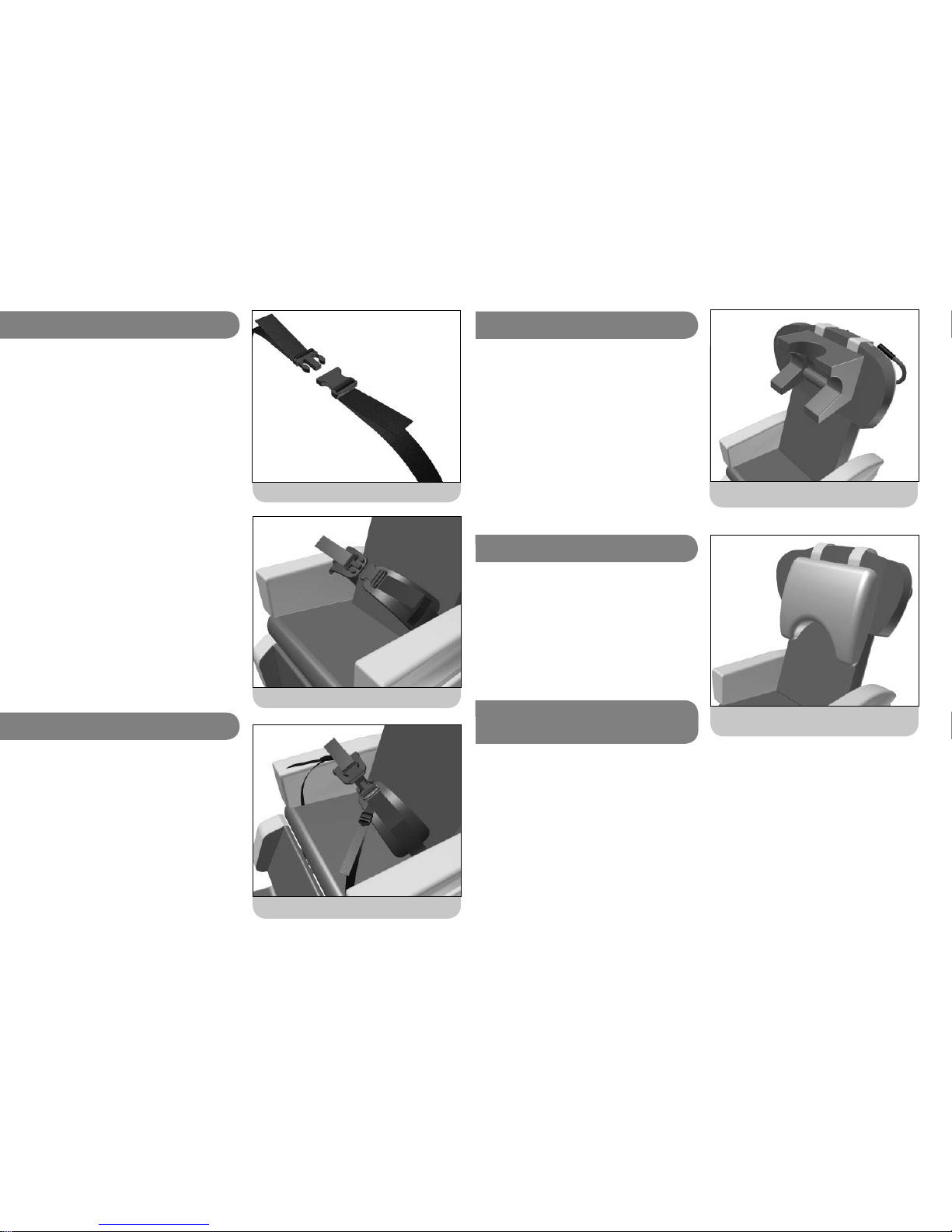
5d. Headrest Types
The Profi led Soft Headrest is a simple pillow of soft
material which will conform to the shape of the client’s
head but which will provide limited lateral control.
The CareFlex InLine headrest provides full cranial support
beneath the occiput and above the ears. This headrest
incorporates memory foam to help reduce incidences of
pressure problems on the ears, cheeks, lower jaw and side
of the head. The InLine headrest is intended to support
the head and neck in a neutral position to help the
client swallow and manage saliva.
18
Profi led soft pillow headrest.
5e. Headrest Set-Up
The set up of the profi led soft headrest comes down to
client comfort. The bottom points of the headrest can be
positioned over the clients shoulders to provide additional
side support.
The InLine Headrest should be set up so that the bottom
edge of the headrest is level with the top of the client’s
shoulders.
The wings of the chair back can be adjusted to
provide greater lateral support for the headrest.
See the earlier instructions for guidance.
Height is controlled by straps coming off the top edge
of the headrest and attaching to velcro closures on
the back of the back cushion cover. The height of the
headrest should be set to provide comfortable support.
Try not to push the client’s head forward or allow it to
tip back as this will affect the client’s ability to swallow
and will cause discomfort.
5f. Headrest Positioning Loose Cover
Pelvic strap with sub-ASIS pads.
Pelvic strap with buckle adjusting from both sides.
5b. Pelvic Straps
The two parts of the buckle on the straps click together.
To release the buckle, press the tabs on the sides of the
buckle and pull the two halves apart.
A pelvic strap is attached to the seat depth frame of
the HydroFlex behind the seat cushion. The strap is
fi tted through the gap between back cushion and the
chair arms and across the client’s hips at a 45° angle.
This strap position is intended to keep the pelvis in an
upright position by pulling the user as far back into
the seat as possible. It is essential that the strap is
always correctly adjusted. Regularly check the tension of
the strap so that the client is correctly supported and
cannot wriggle beneath, or otherwise become trapped
by the strap.
The buckle on the strap is adjustable from both sides
which helps to keep the buckle located centrally. To
tension the pelvic strap, pull the loose ends of the
webbing straps coming from the buckles.
The pelvic strap with sub-ASIS pads should be used if the
client is sensitive to pressure across the bony ridges on
the front of their pelvis.
17
4-point pelvic strap.
5c. 4-point Pelvic Strap
The 4-point pelvic strap offers greater stability as
secondary straps keep the strap at the correct height
across the pelvis. The secondary straps come down over
the sides of the thigh and attach to the underside of the
seat. The secondary straps have individual adjustment to
help keep the main strap positioned at the correct height.
Once the main strap is correctly positioned the secondary
straps should be tensioned to prevent the main strap
moving upwards. To adjust the secondary straps, pull
the loose ends of the webbing straps fi tted through the
ladder lock buckles.
Page 10
UI HydroFlex. iss4 01/11 UI HydroFlex. iss4 01/11
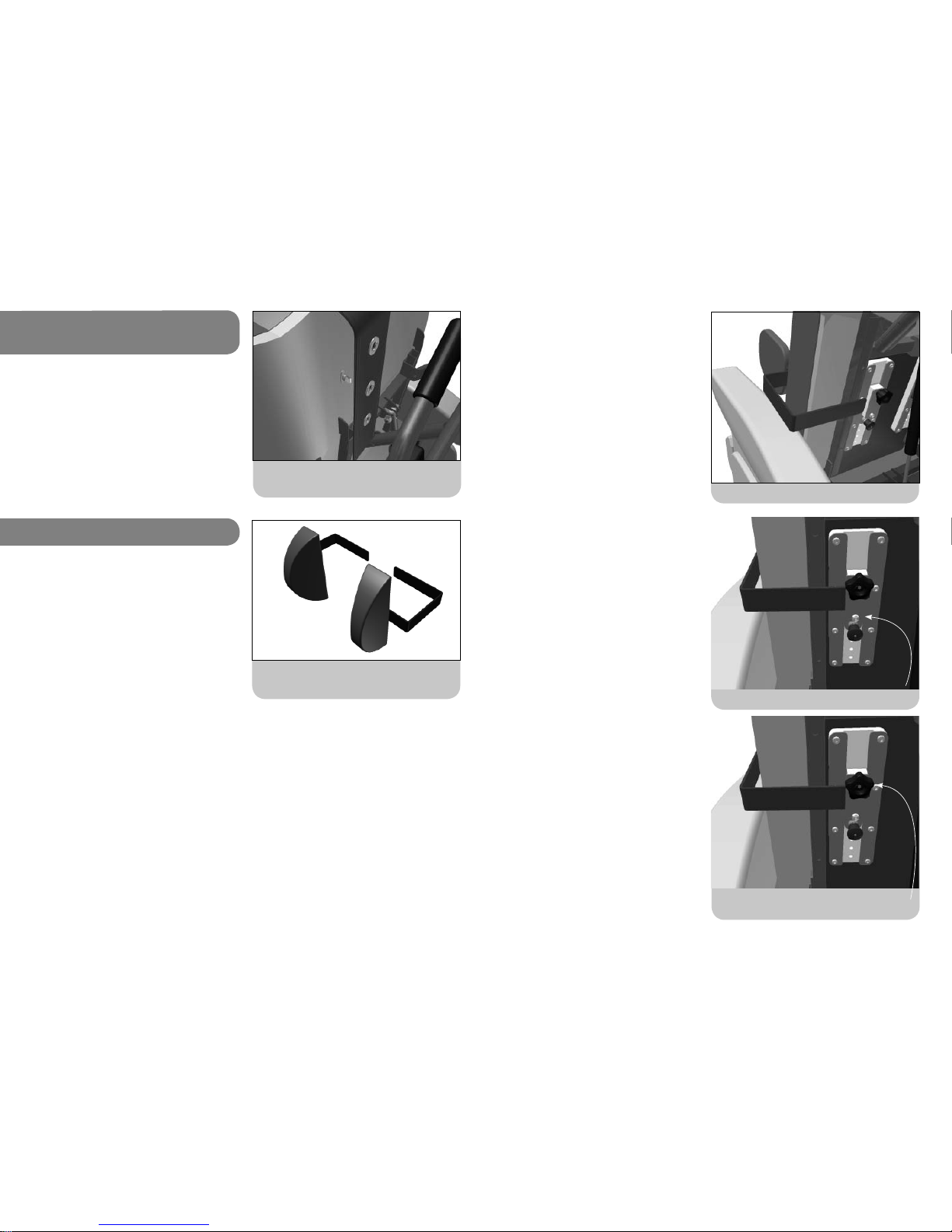
5h. Adjustable Laterals
The turn buckles hold the headrest straps in place
on the fi xed cover version of the chair.
On the fi xed cover version of the HydroFlex, the headrest
is positioned on ‘turn buckles’. These are fi ttings attached
to the back of the headboard over which eyelets in the
headrest strap are hooked.
Turn the buckles so that they are lined up vertically to
un-hook the eyelets and adjust the strap. Fit the eyelets
back on to the turn-buckles so that the headrest is held
at the appropriate height and turn the buckles through
a quater turn to hold the straps in place.
The adjustable laterals should be used to counter any
tendency for a client to lean to one side. They are not
suitable for more active clients who are able to manage
their own posture or who tend to rock backwards and
forwards or who are ataxic.
Two types of pad are available for the HydroFlex
adjustable lateral system.; regular pads and kidney pads.
The regular pads have a regular, deep ‘D’ with an angled
face at the back to fi t around the chest to provide a
large support area. The regular pads can be fi tted either
side of the chair.
Kidney pads come as a left and right hand pair. These
have a tear drop profi le and a larger, angled contact
surface which gives less prescriptive support. To discern
left from right, position the kidney pad laterals as if they
were on a chair. The more pointed end should be towards
the top of the pad with the rounded end indicating the
bottom of the pad.
The adjustable laterals can be adjusted up and down and
in and out to provide the necessary support. They adjust
individually and so can be set up to suit an asymmetric
posture such as scoliosis.
19
5g. Headrest Positioning Fixed Cover
Lateral supports are intended
to provide fi rm support for the
client’s trunk. They may not be
appropriate for those clients
who are susceptible to pressure
damage around their ribs. If
the client is susceptible to
pressure damage the laterally
contoured back option may be
more appropriate.
Kidney pad adjustable laterals, more pointed end
upwards to make a handed pair.
left
right
Lateral supports are usually adjusted so that they are
supporting the client’s thorax (upper chest). The laterals
must be adjusted so that the majority of the lateral is
above the client’s lower rib. There is no point in fi tting
the laterals against the sides of the client’s abdomen or
just above their waist as these areas are fl exible and
the client will end up leaning over the pad. For comfort
leave a three fi nger gap between the top of the lateral
and the client’s armpit.
Before transferring the client into the HydroFlex take a
measurement of the height of any lateral support they
have fi tted to a wheelchair or activity chair. Otherwise,
try to measure from seat to mid chest height. The
laterals can then be adjusted to this height prior to
transferring the client to the chair.
Similarly, measure the distance between the lateral
supports on the client’s wheelchair or across their chest
so that the width between the laterals can be set up
before transfer.
To adjust lateral height, pull out the lower knob on the
adjustment block fi tted to the back of the chair back.
This knob controls the indexing pin which locks into the
holes in the height adjuster. Raise or lower the lateral
pad to the desired height and release the knob. Push the
lateral down until the indexing pin is felt to lock in place.
Width is controlled by the clamp plate on the adjustment
block. Turn the handwheel on the adjustment block until
the lateral is free to slide sideways. Once in the desired
position tighten the handwheel to lock the pad in place.
If the HydroFlex is to be used without the adjustable
laterals undo the handwheel controlling the width
adjustment and slide the laterals completely out of the
adjustment blocks. Keep the laterals in a safe place for
future use.
Please refer to the later instructions to retro-fi t the
Adjustable Lateral System.
Turn the handwheel to adjust lateral width and
tighten the handwheel to hold the setting.
Pull out the lower knob to adjust lateral height.
Fit the lateral armature into the adjustment block.
20
Page 11
UI HydroFlex. iss4 01/11 UI HydroFlex. iss4 01/11
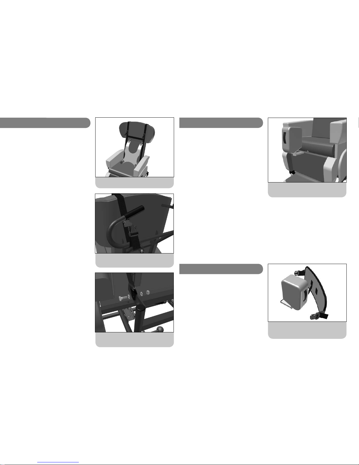
Fit the tab on the inside face of the knee strap
through the loop on the front of the pommel.
Fit the pommel into the bracket in the middle of
the bottom edge of the seat.
5k. Pommel
A pommel can be used to control knee position, usually
by abducting (pushing apart) the knees to help keep the
seating position stable and level. The pommel is designed
to separate the knees and support the whole inside of
the knee joint. For this reason the pommel is not depth
adjustable and sticks out in front of the seat edge.
A pommel must never be used as a restraint and the
client must not be allowed to slide into sacral sitting and
come to rest against the pommel.
Fit the pommel with the legrest angled down as this will
give the best access to the bracket.
To fi t the pommel, locate the cut-out in the bottom front
edge of the seat cushion The opening for the pommel
bracket is located in this cut-out. Fit the metal stem of
the pommel into the bracket and push the pommel until
it is felt to click into position.
To remove the pommel, hold it at the bottom edge of
the metal stem and pull directly outwards.
5l. Anterior Knee Strap
Only used in conjunction with the pommel, the anterior
knee strap fi ts across the front of the knees, preventing
the client sliding forward and helping to keep the pelvis
in the back of the seat. The anterior knee strap can
be used as an alternative to a groin harness to help
maintain client position.
The strap must cover the whole of the knee (not sit below
it) and should not be used by clients with damaged hip
and/or knee joints or those with a history of hip and/
or knee pain.
22
Fit the buckle closures at the top of the harness
around the push handles.
5i. Four point Chest Harness
Four point chest harness.
Fit the A plates at the bottom of the harness to
the seat depth frame.
A four point chest harness keeps the user in an upright
and ‘midline’ position and is very effective at controlling
lateral movement. However, their use must be carefully
considered, especially if the client has a stoma or feeding
device implanted in their abdomen. A four point harness
should never be used as a restraint.
The harness consists of a padded bib shape held in
position with a strap from each corner. Two straps attach
to the chair at the client’s waist and two over their
shoulders. The straps are attached to the harness with
side-lock buckles. The length of the webbing straps can
be adjusted through the buckles.
To use the harness undo one of the lower buckles and
both buckles which fi t over the shoulders. Hang the
bib section of the harness over the side of the chair
and position all straps so that the client cannot sit on
them when they are transferred into the chair. Transfer
the client into the chair, position the bib section of the
harness in front of them and fasten the buckles at the
waist and shoulders. Ensure the belts are suffi ciently
tight to help support the client but are not tightened
to the point where they restrict breathing or cause
discomfort.
The four point chest harness is fi tted to a web which
fi ts over the back of the HydroFlex. Fasten the buckles
on the top of the web around the push handle and bolt
the A plates on the bottom of the web onto the pelvic
strap mounting holes in the seat depth frame. Tension the
web by pulling tight the webbing on the buckles attached
around the push handle.
Slide the tri-glides on the web to the level of the clients
shoulders to hold the shoulder straps at the correct
height.
21
Page 12
UI HydroFlex. iss4 01/11 UI HydroFlex. iss4 01/11
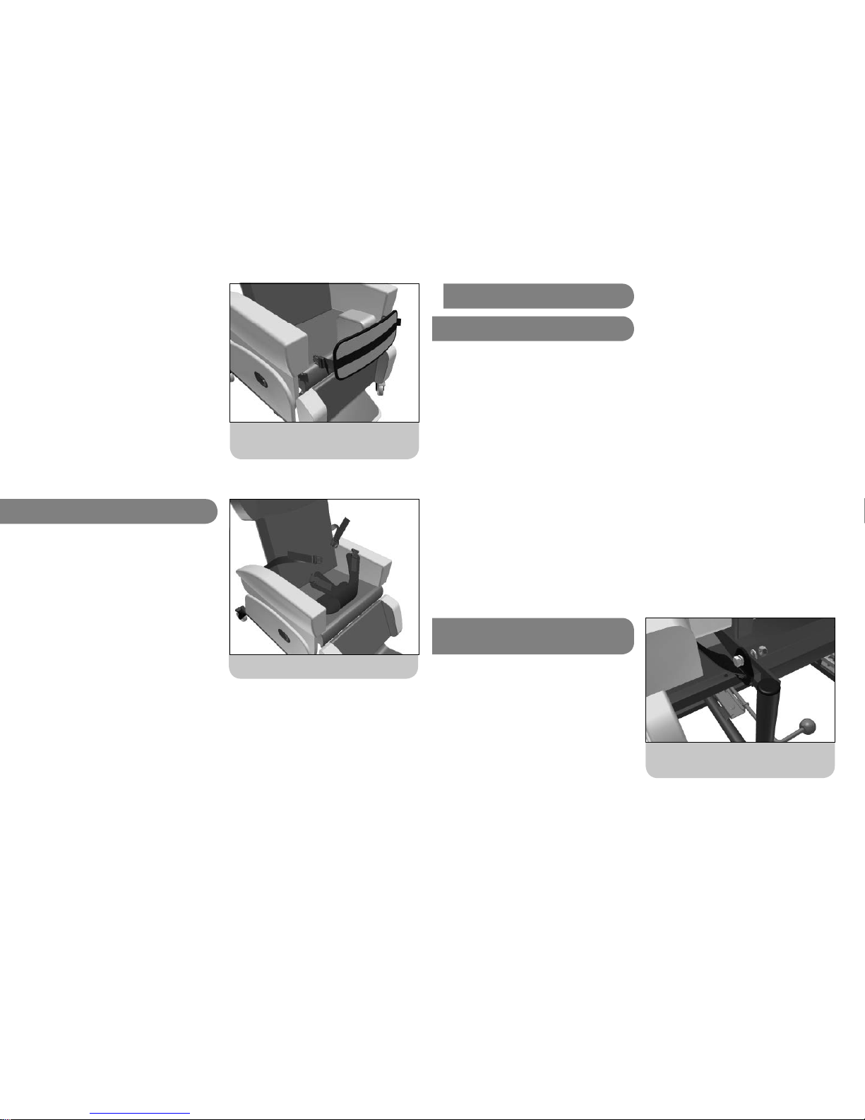
Positioning the groin harness for transfer.
Connecting the buckles on the sides of the knee
strap to the connectors attached to the chair.
A tab on the inside face of the knee strap fi ts through
the webbing loop on the front of the pommel and closes
onto a velcro patch. This controls the height of the strap
relative to the pommel.
The padded strap is attached to the pommel and
attaches to the connectors on the sides of the chair with
a two part buckle (See further instructions for fi tting
connectors).
Fasten the two parts of the buckle and tension the straps
as necessary.
The anterior knee strap must not be used as a restraint.
5j. Groin Harness
A groin harness helps to keep the user positioned
correctly in the chair.
The groin harness needs to be fi tted to the chair before
it is used. See the notes at the end of these instructions
on groin harness fi tting.
Position the loose webbing straps over the arms of the
chair and transfer the client onto the chair so that they
are sitting on the groin harness.
Position the ends of the groin harness with the buckles
attached over the client’s thighs and connect the buckles
to the webbing straps.
Adjust the length of the webbing straps through the
buckles so that the groin harness helps control the
client’s position.
Do not over-tighten the straps as
this may lead to discomfort. The
groin harness must not be used as a
restraint.
23
If a groin harness is fi tted and left
loose the client may slide into
sacral sitting which is a posture
which will make them vulnerable
to skin damage through shear
& will cause discomfort and
pressure in the groin area.
6. Accessory Fitting
6a. Tools
In day to day use, the HydroFlex does not require
tools to make changes and adjustments. However, it is
necessary to use tools to fi t some of the accessories
to the chair. Before attempting to fi t these accessories,
gather together the right tools. These are;
• Two 13mm spanners.
• 4mm allan key.
• Sharp craft knife.
Do not attempt to undo nuts and bolts using pliers or
other grip type tools.
The nuts used on the HydroFlex are Nyloc types. These
are designed not to come loose. They must also be
fastened in place with spanners. Any nuts and bolts which
are only tightened ‘fi nger tight’ will soon come undone.
Always use spanners and ensure any assembly is fully
tightened and is free of play and rattle before use.
6b. Pelvic strap and Groin
Harness fi tting
Both the pelvic straps and the groin harness are held in
place on two ‘A’ plates which bolt onto the seat depth
adjustment frame. There is an 8mm hole in the traingular
plates of the seat depth frame for attaching the A plates.
Fit the ‘A’ plates to the outside of the plates on the seat
depth frame with the hole through which the webbing
passes pointing down. Fit a bolt through the ‘A’ plates
and frame and tighten them together with a Nyloc nut.
Ensure the assembly is fully tightened so that the ‘A’
plate cannot revolve on the bolt.
Fully tighten the Nyloc onto the bolt with two
13mm spanners, slot in ‘A’ plate pointing down.
24
Page 13
UI HydroFlex. iss4 01/11 UI HydroFlex. iss4 01/11
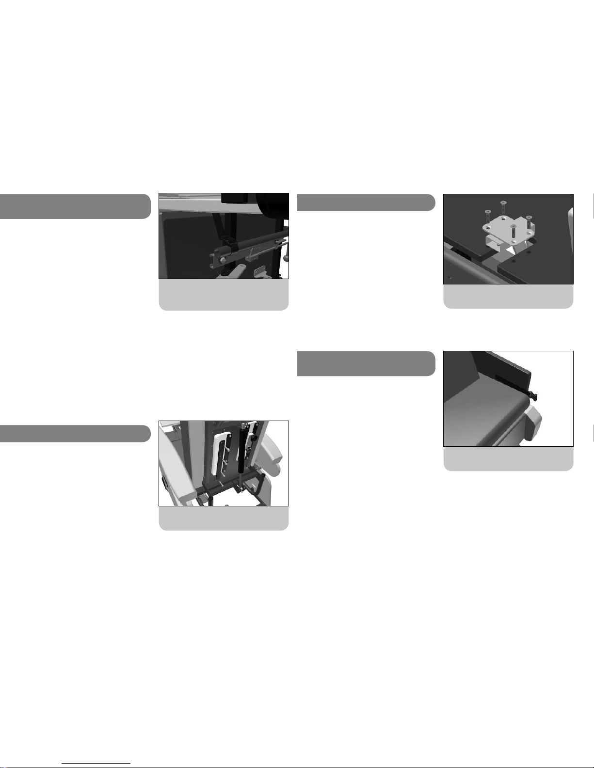
Wrap the straps around the tube and thread the
ends through the ladder locks. The strap goes in
front of the square cross bar.
6c. 4-point Pelvic Strap Front
Strap Fitting.
The 4-point pelvic strap has two front straps which need
to be attached to the chair.
The chair needs to be tipped onto its side to gain access
to this position. This is a two person operation and a
sheet or large piece of card should be put down for
the chair to be tipped onto to protect the chair from
damage.
The straps are fi tted through the gap between the round
tube and the seat depth adjustment rails, in front of the
square cross bar of the seat frame.
The straps need to be looped around the tubes of
the seat depth adjustment frame and threaded though
the ladder lock sewn onto the ends. The straps are
then positioned through the gaps on each side of the
seat board and the chair sides. The straps can then be
threaded though the ladder locks sewn onto each pad of
the 4-point pelvic strap.
6d. Adjustable Guides
The adjustable lateral support system is based on two
guides which fasten to the back of the lumbar board.
The lumbar board is fi tted with threaded inserts which
the holding screws fasten into.
Feel through the covering material on the back of the
board for two sets of eight indentations. Carefully score
over these indentations with a sharp craft knife to access
the threaded inserts.
Position the guides and metal guide plates over the
inserts and fasten them in place with the button head
screws. Use a 4mm allan key to fully tighten the screws.
Score over the recesses in the back board and
screw the guides into place.
25
Note: If a specifi c position is required for the front straps
they can be screwed to the underside of the seat board.
Use a chipboard screw with a maximum length of 16mm
to do this.
6e. Pommel Bracket
Begin by carefully removing the seat cushion. The pommel
bracket fi ts in a recess cut into the front edge of the
seat board. The seat board is fi tted with threaded inserts
which the holding screws fasten into.
Feel through the covering material on the front edge of
the seat board, either side of the recess, for two sets of
two indentations. Carefully score over these indentations
with a sharp craft knife to access the threaded inserts.
Position the bracket in the recess and fasten it in place
with the supplied counter-sunk machine screws. Use a
large posi-drive screw driver to fully tighten the screws.
Score over the two recesses each side of the notch,
position the bracket and screw in place.
6f. Anterior Knee Strap
connectors
The connectors to which the anterior knee strap is fi tted
are held in place by velcro straps which are sandwiched
between the chair arms and sides.
Carefully remove the arms to reveal the strips of hook
velcro on the inside of the chair sides.
Position the connectors on the velcro strips so that the
top of the buckles are level with the top of the seat
cushion and they protrude forwards of the chair sides.
Carefully re-position the arms over the chair sides and
connectors and ensure they are properly positioned
before the chair is used.
Please note; The anterior knee strap
cannot be retro-fi tted to fi xed cover
versions of the HydroFlex.
Attaching the connectors to the velcro on the
chair sides.
26
Page 14
UI HydroFlex. iss4 01/11 UI HydroFlex. iss4 01/11
Looking after the chair
Every time it is used, check the chair over for signs of damage or excessive wear.
If the chair shows signs of excessive wear, damage or incorrect performance, please
take it out of service immediately and contact CareFlex .
If the client is experiencing severe discomfort, do not use the chair. Take it out of
service immediately and contact CareFlex or your local CareFlex Distributor.
The chair is upholstered in high quality materials which are waterproof and fi re
retardant. However, do not store or use the chair in damp or wet areas. Similarly, do
not position the chair near or against sources of direct heat or naked fl ames. Covering
materials may fade or degrade if subjected to excessive heat or sunlight.
Refer to the CareFlex fabric guide for upholstery cleaning details.
Wipe up spills and contamination as soon as they are noticed. Stains and soiling can
lead to staining and more severe infection control issues if not addressed immediately.
Do not attempt to carry out any structural maintenance or adjustment of the chair or
its accessories without consulting CareFlex.
For motorised chairs, regularly charge the batteries as per the earlier instructions.
For cleaning and decontamination procedures, refer to the appropriate section of the
Fabric and Cleaning Guide supplied with the chair. Carefl ex use a range of covering
materials, each with particular characteristics and specifi c cleaning guidelines. If you are
unsure of the chair’s covering material, contact CareFlex with the serial number for
the chair which will allow CareFlex to trace the specifi cation of the chair.
27
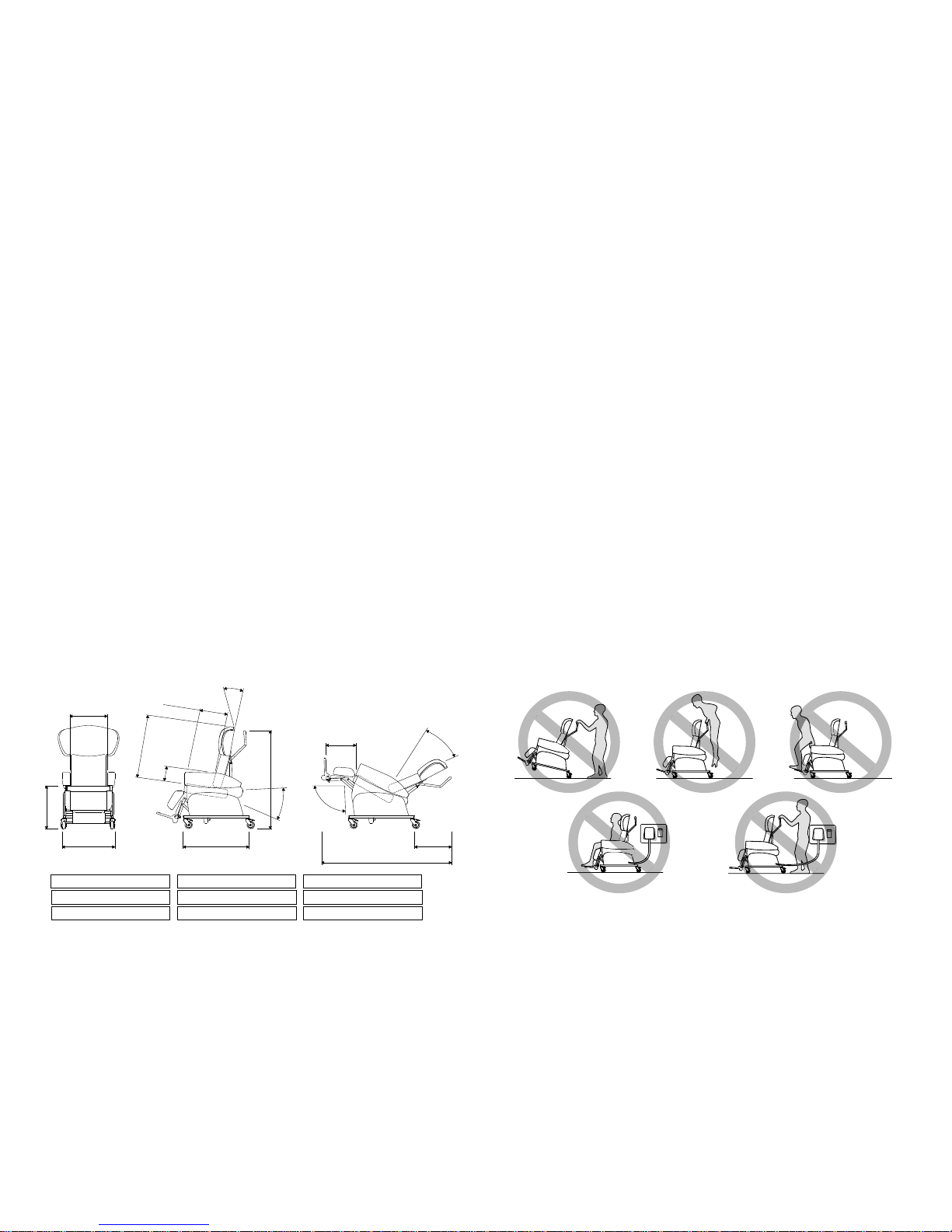
Small: 38, 41, 44, 47
Medium: 50, 53, 56
Small: 28, 33, 38, 43
Medium: 35, 40, 45, 50
Small: 59
Medium: 69
S
m
a
l
l
:
3
5
-
5
0
M
e
d
i
u
m
:
3
8
-
5
3
S
m
a
l
l
: 7
5
M
e
d
iu
m
:
8
5
S
m
a
ll
: 1
8
,
2
1
M
e
d
iu
m
: 2
2
, 2
5
Small: 115 (average)
Medium: 120 (average)
H
o
riz
o
n
t
a
l
t
o
3
0
°
t
ilt
95° at hips to 125°
80° to 170°
Small: 34 to 40
Medium: 41 to 49
Small: 78
Medium: 87
Small: 163
Medium:179
Small: 58
Medium: 59
Weights SMALL HYDROFLEX MEDIUM HYDROFLEX
Product Weight
100kg
70kg
150kg
75kg
Max User Weight
9
0
°
t
o
5
5
°
Important Safety Information
• Please take the time to familiarise yourself with all the aspects of the chair
and its functions before using the chair.
• Do not ‘ride’ on the push handles or subject them to excessive loads.
• Do not sit on the legrest or subject it to excessive loads.
• Do not attempt to stand on the footplate.
• Do not tip the chair backwards to ascend steps or overcome thresholds,
especially if a client is sat in the chair.
• Always ensure that the client’s feet do not drag on the ground when the
chair is moved by elevating the legrest to lift their feet off the fl oor.
• Always ensure that there are no obstructions under the chair and that
there is plenty of space around the chair before using the back angle recline
facility.
• Always apply at least two brakes when the client is transferred to or from
the chair.
• Always try to avoid storing or using the chair in areas where it may obstruct
exits or passageways.
• The HydroFlex must never be used in motor vehicles for client transportation.
• Do not charge the chair’s batteries when a client is sat in the chair (ProControl and Motorised versions).
• Do not move the chair if the charging lead is connected between the chair
and mains power supply.
CareFlex Ltd. Unit 1, Templer House, King Charles Business Park, Old Newton Road, Heathfi eld, Devon. TQ12 6UT.
Tel: 01626 831440 www.carefl ex.co.uk
28
 Loading...