

Cardiovascular Systems, Inc. DIAMONDBACK 360 Peripheral Orbital Atherectomy System Exchangeable Series, DIAMONDBACK 360 Instructions For Use Manual

_______________________________________ _____________
DIAMONDBACK 360
®
Peripheral Orbital Atherectomy
System Exchangeable Series
Including the Orbital Atherectomy Device, Handle, Orbital
Atherectomy Cartridge, Saline Pump, VIPERWIRE ADVANCE®
Peripheral Atherectomy Guide Wire, and VIPERWIRE
ADVANCE® with FLEXTIP Peripheral Atherectomy Guide Wire
Instructions for use
_______________________________________ _____________
Caution: Federal Law (USA) restricts this device to sale by or on the order of a
physician.
The following are trademarks of Cardiovascular Systems, Inc.:
CSI®, Cardiovascular Systems®, DIAMONDBACK 360®, VIPERWIRE®, VIPERWIRE
ADVANCE®, VIPERWIRE ADVANCE® with FLEXTIP, VIPERSLIDE®, GlideAssist
®

Explanation of Symbols on Package Labels
Refer to the package labels to see which symbols apply to specific products.
Lot number
Model number
Consult IFU www.csi360.com (USA) (Symbol appears in blue when
placed on the device itself)
Caution: Consult IFU www.csi360.com (USA)
Do not reuse.
Do not re-sterilize
Sterilized with Ethylene Oxide
Manufacturer
Use by
Maximum guide wire tip diameter
Maximum guide wire shaft diameter
Guide wire length
Caution: Federal law (USA) restricts this device to sale by or on
the order of a physician.
Contains phthalates

Explanation of Symbols on the Saline Pump
Low saline red LED indicator
Start button and pump ON green LED indicator
Pump status yellow LED indicator
Prime button
Type CF Applied Part
Slow Blow Type T Fuse

Explanation of Symbols on the Handle
Prime button
Low speed button
Medium speed button
High speed button
Rotate Symbol
Eject Symbol
Non-continuous use; spin cycles of 30 seconds on, 30
seconds off with maximum spin time of ≤ 8 minutes per
cartridge using no more than three cartridges per handle

Table of Contents
1. System Description................................................................................................ 1
2. System and Component Descriptions ................................................................... 1
3. Indications for Use ................................................................................................. 9
4. Contraindications ................................................................................................... 9
5. Restrictions .......................................................................................................... 10
6. Warnings ............................................................................................................. 10
7. Precautions ......................................................................................................... 11
8. Storage and Handling .......................................................................................... 13
9. Adverse events .................................................................................................... 13
10. Clinical Trials Summary ....................................................................................... 14
11. Equipment, Setup, and Test ................................................................................ 14
12. OAS Directions for Use ....................................................................................... 22
13. Specifications ...................................................................................................... 32
14. OAS Pump Declaration of Conformity ................................................................. 34
15. EMC Declaration ................................................................................................. 34
16. FCC ..................................................................................................................... 37
17. Disclaimer of Warranty ........................................................................................ 37
Appendix A. System Troubleshooting ........................................................................... 39
Appendix B. Introducer, Guide Sheath, or Guide Catheter Size .................................... 44
Appendix C. Maximum Orbit and Resulting Lumen Diameter ....................................... 46
Appendix D. Orbit Performance .................................................................................... 48

1
1. System Description
The Cardiovascular Systems, Inc. (CSI) DIAMONDBACK 360 Peripheral Orbital Atherectomy
System (OAS) Exchangeable Series is a minimally invasive, catheter-based OAS designed for
improving luminal diameter in patients with peripheral arterial disease (PAD). PAD is caused by
the accumulation of plaque in the arteries of the leg or foot and reduces blood flow that may
lead to pain, tissue loss, and eventual foot amputation, leg amputation or death. This system
treats a broad range of plaque types in the lower limbs and reduces or removes occlusive
material by using a spinning, orbiting diamond-coated crown, within peripheral arteries, in order
to restore lumen patency.
The OAS consists of a hand-held CSI DIAMONDBACK 360 Orbital Atherectomy Device (OAD),
the CSI Saline Pump (OAS pump), the CSI VIPERWIRE ADVANCE Peripheral Atherectomy
Guide Wire (guide wire) or CSI VIPERWIRE ADVANCE with FLEXTIP Peripheral Atherectomy
Guide Wire (guide wire), and the CSI VIPERSLIDE Lubricant (lubricant).
The Exchangeable Series allows for multiple treatment options by offering a variety of
cartridges, with different crown sizes, for use with a single handle. The Exchangeable Series
OAS cartridges are intended to provide variable crown sizes during a procedure. The cartridges
should be utilized for the treatment of multiple lesions to achieve full-leg revascularization. The
following Exchangeable Series package options are available:
• OAD - handle, cartridge, and saline line
• Handle-only with a saline line
• Cartridge-only
2. System and Component Descriptions
2.1. Orbital Atherectomy Device (OAD) Description
The OAD is a hand-held, over-the-wire device consisting of a handle, a cartridge, and a
saline line (Figure 1). The cartridge includes a sheath-covered drive shaft and a
diamond-coated crown. The diamond coating on the crown provides an abrasive surface
with which to reduce or remove occlusive material within peripheral arteries. The handle
includes control buttons for operating the OAD and contains the motor and electronics
that power the rotation of the drive shaft. The GlideAssist feature facilitates advancing
and retracting the OAD crown over the guide wire.
Warning: The device is designed to track and spin only over the CSI Peripheral
VIPERWIRE ADVANCE Guide Wire or the VIPERWIRE ADVANCE with FLEXTIP Guide
Wire. Do not use any other guide wire with this device.
Select a crown size according to the crown’s ability to cross the lesion within the minimum
proximal reference vessel diameter at the treatment site. See Table 1, Table 2, and
Table 3 for available crown sizes. See Appendices C and D for orbit performance.

2

3
Table 1: Micro Crowns
Model Number
Type
Crown Size
Shaft
Length
Nose
Length*
DBP-EX-125MIC145
DBP-CART-125MIC145
OAD
Cartridge
1.25 mm
145 cm
7 mm
DBP-EX-125MIC75
DBP-CART-125MIC75
OAD
Cartridge
1.25 mm
75 cm
7 mm
*Nose length is the length of the drive shaft from the crown to the distal tip of the shaft.
Table 2: Solid Crowns
Model Number
Type
Crown Size
Shaft Length
Nose Length*
DBP-EX-125SOL75
DBP-CART-125SOL75
OAD
Cartridge
1.25 mm
75 cm
7 mm
DBP-EX-125SOL145
DBP-CART-125SOL145
OAD
Cartridge
1.25 mm
145 cm
7 mm
DBP-EX-150SOL145
DBP-CART-150SOL145
OAD
Cartridge
1.50 mm
145 cm
10 mm
DBP-EX-200SOL145
DBP-CART-200SOL145
OAD
Cartridge
2.00 mm
145 cm
30 mm
DBP-EX-125SOL200
DBP-CART-125SOL200
OAD
Cartridge
1.25 mm
200 cm**
10 mm
DBP-EX-150SOL200
DBP-CART-150SOL200
OAD
Cartridge
1.50 mm
200 cm**
10 mm
DBP-EX-175SOL180
DBP-CART-175SOL180
OAD
Cartridge
1.75 mm
180 cm**
30 mm
*Nose length is the length of the drive shaft from the crown to the distal tip of the shaft.
**180 cm and 200 cm length devices are intended to accommodate patient anatomy and physician
preferred access methodology, for example radial access. See Section 10.3 Initiating the Atherectomy
Procedure.
Table 3: Classic Crowns
Model Number
Type
Crown Size
Shaft
Length
Nose
Length*
DBP-EX-150CLA145
DBP-CART-150CLA145
OAD
Cartridge
1.50 mm
145 cm
15 mm
DBP-EX-200CLA145
DBP-CART-200CLA145
OAD
Cartridge
2.00 mm
145 cm
20 mm
*Nose length is the length of the drive shaft from the crown to the distal tip of the shaft.

4
Figure 1. OAD - includes the handle, cartridge, and saline line
______________________________________________________________________
Cartridge
A. Nose length
B. Crown
C. Saline sheath
D. Rotation grips
E. Saline line port connector
Handle
F. Crown advancer knob
G. On/Off button
H. Cartridge eject button
I. Speed buttons and indicators
J. Brake light indicator
K. Prime button
L. Guide wire brake lever
M. Electrical power cord
Saline line
N. Saline line port connector
O. Injection port
P. Saline tubing positioners
Q. Saline tubing

5
R. Saline bag spike
OAD Features:
• On/Off Button to control when the crown starts and stops
• 3 speed control buttons with LED indicators to select the crown rotation speed
• Saline prime button
• 15 cm crown advancement with travel measurement indicators
• Ability to lock crown advancer knob to maintain crown position relative to handle
• Manual guide wire brake to restrict both the rotational and axial movement of the
guide wire with a LED indicator
• Eccentrically-mounted, diamond-coated crown that provides an abrasive surface with
which to reduce or remove occlusive tissue
• GlideAssist to facilitate advancing and retracting the OAD crown over the VIPERWIRE
guide wire.
• Ability to separate the cartridge from the handle to allow the use of multiple cartridges
in one case
• Crown advancement measurement indicators
• Able to load guidewire through proximal end of OAD

6
2.2. Package Contents: OAD, Handle, Or Cartridge
2.2.1. OAD
The OAD and accessories are supplied sterile and are for single-use only. Each
package contains:
• OAD (fully assembled – one handle and one cartridge)
• Saline line (connects the OAD to the OAS pump)
2.2.2. Handle
The handle and accessories are supplied sterile and are for single-use only. Each
package contains:
• One handle
• Saline line (connects the OAD to the OAS pump)
2.2.3. Cartridge
The cartridge is supplied sterile and is for single-use only. Each package contains:
• One cartridge
2.3. OAS Pump Description
The OAS pump provides the saline pumping mechanism and power to the device. The
small, reusable, and portable OAS pump attaches to a standard five-wheel rolling
intravenous (IV) pole (Figure 2) and plugs in to a wall power outlet. The OAS pump
includes a built-in, audible 25 second spin time notification, system power and priming
buttons, and status indicators.

7
Figure 2. OAS Pump
______________________________________________________________________
A. IV pole screw clamp
B. IV pole (not included)
C. Low saline level sensor and connector cord
D. Control panel
E. OAS Pump door
F. OAD connection
______________________________________________________________________
2.4. OAS Pump Package Contents
The OAS pump and accessories are supplied non-sterile. Each package contains:
• OAS Pump with attached IV pole screw clamp
• Power cord
• Low saline level sensor and connector cord
2.5. VIPERWIRE ADVANCE Peripheral Guide Wire Description
The guide wire is a smooth, stainless steel wire, with a silicone coating, and a radiopaque
distal spring tip (Figure 3). The guide wire allows for proper positioning of the OAD crown
within peripheral arteries and provides a center of rotation for the OAD drive shaft. The
guide wire torquer is a small, plastic accessory, packaged with the guide wire, and
provides a gripping surface for manipulating the guide wire, if desired. Guide wires are
available in a variety of spring tip diameters (Tables 4 and 5).

8
Figure 3. Guide wire
______________________________________________________________________
A. Distal spring tip
______________________________________________________________________
Table 4 VIPERWIRE ADVANCE Peripheral 0.014” Guide Wires
OAD Device
Shaft Length
Compatibility
Model Number
Guide wire
Spring Tip
Diameter
Guide
wire
Length
75 and 145 cm
VPR-GW-14
0.014”
335 cm
75 and 145 cm
VPR-GW-17
0.017”
335 cm
180 and 200 cm
VPR-GW-EL14
0.014”
475 cm
180 and 200 cm
VPR-GW-EL18
0.018”
475 cm
Table 5 VIPERWIRE ADVANCE with FLEXTIP Peripheral 0.014”Guide Wire
OAD Device
Shaft Length
Compatibility
Model Number
Guide wire
Spring Tip
Diameter
Guide
wire
Length
75 and 145 cm
VPR-GW-FT14
0.014”
335 cm
75 and 145 cm
VPR-GW-FT18
0.018”
335 cm
75 and 145 cm
VPR-GW-FLEX14
0.014”
335 cm
75 and 145 cm
VPR-GW-FLEX18
0.018”
335 cm
180 and 200 cm
VPR-GW-ELFLEX14
0.014”
475 cm
180 and 200 cm
VPR-GW-ELFLEX18
0.018”
475 cm

9
2.6. VIPERWIRE ADVANCE Peripheral Guide Wire Package Contents
The guide wire and guide wire torquer are packaged separately from the OAD, are
supplied sterile and are for single-use only. Each VIPERWIRE ADVANCE package
contains:
• Five (5) guide wires
• Five (5) torquers
2.7. Lubricant Description
VIPERSLIDE Lubricant reduces friction between the OAD drive shaft and the guide wire.
It is packaged separately from the OAD.
Note: Please refer to the VIPERSLIDE Lubricant IFU prior to starting the atherectomy
procedure.
3. Indications for Use
The DIAMONDBACK 360 Peripheral Orbital Atherectomy System Exchangeable Series is a
percutaneous orbital atherectomy system indicated for use as therapy in patients with occlusive
atherosclerotic disease in peripheral arteries and who are acceptable candidates for
percutaneous transluminal atherectomy.
The OAS supports removal of stenotic material from artificial arteriovenous dialysis fistulae (AV
shunt). The system is a percutaneous orbital atherectomy system indicated as a therapy in
patients with occluded hemodialysis grafts who are acceptable candidates for percutaneous
transluminal angioplasty.
4. Contraindications
Use of the OAS is contraindicated in the following situations:
• The guide wire cannot be passed across the peripheral lesion.
• The system cannot be used in coronary arteries.
• The target lesion is within a bypass graft or stent.
• The patient has angiographic evidence of thrombus; thrombolytic therapy must be
instituted prior to atherectomy.
• The patient has angiographic evidence of significant dissection at the treatment site. The
patient may be treated conservatively to permit the dissection to heal before treating the
lesion with the OAS.

10
5. Restrictions
The OAS should only be used by physicians who are experienced in peripheral angioplasty at
their institutions and trained on the use of the OAS. Contact a CSI representative for information
on training.
6. Warnings
• Do not use the OAD in a vessel that is too small for the crown. The reference vessel
diameter at the treatment area must be at least 2.00 mm in diameter for the 1.25mm micro
crown.
• If mechanical failure of the OAD occurs before or during the atherectomy procedure,
discontinue use immediately. Do not attempt to use a damaged OAD or other system
component. Use of damaged components may result in system malfunction or patient injury.
• Do not use the OAD during spasm of the vessel.
• Only use the approved CSI VIPERWIRE ADVANCE 0.014-inch (0.3556 mm) × 335-cm
guide wires for 75cm and 145 cm length CSI crown and shaft configurations. Only use the
approved CSI VIPERWIRE ADVANCE 0.014-inch (0.3556 mm) x 475 cm guide wires for
180 cm and 200 cm length CSI crown and shaft configurations. See Table 4 and Table 5 for
the appropriate guide wire to use based on the OAD shaft configuration. Follow CSI’s
instructions related to guide wire use.
• Do not continue treatment if the guide wire or the OAD becomes sub-intimal.
• Immediately stop use if the OAD stalls. Review for complications and mechanical failure if a
stall condition occurs. Do not change to a higher speed if the OAD stalls.
Note: If a stall occurs, the On/Off button is inactive for five seconds. If the On/Off
button is pressed during this five second lockout period, the lockout period will begin
again.
• Performing treatment in vessels or bifurcations that are excessively tortuous or angulated
may result in vessel damage.
• Always use fluoroscopy when advancing the guide wire to avoid misplacement, dissection,
or perforation. The OAD tracks over the guide wire, so it is imperative that the guide wire be
initially placed through the stenotic lumen and not in a false channel.
• Do not inject contrast while OAD crown is spinning. OAD failure or patient harm may occur.
• Handle the OAD and guide wire carefully. A tight loop, kink, or bend in the guide wire may
cause damage and system malfunction during use.
• Never operate the OAD without normal saline and lubricant solution. Flowing saline and
lubricant solution is required for cooling and lubricating the OAD during use to avoid
overheating and permanent damage to the OAD and possible patient injury.
• The crown at the distal tip of the OAD operates at very high speeds. Do not allow body parts
or clothing to come into contact with the crown. Physical injury or entanglement may occur.
• Never advance the orbiting crown to the point of contact with the guide wire spring tip. Distal
detachment and embolization of the tip may result.

11
• Always advance the orbiting, abrasive crown by using the crown advancer knob. Never
advance the orbiting crown by advancing the shaft or handle. Guide wire buckling may
occur, and perforation or vascular trauma may result.
• Always keep the crown advancing or retracting while it is at high rotational speeds. Do not
allow the crown to remain in one location for more than 2–3 seconds. Maintaining the crown
in one location while it is orbiting at high speeds may lead to excessive tissue removal.
• Do not start or stop orbiting of the crown when tight in a lesion.
• Never force the crown when rotational or translational resistance occurs; vessel perforation
may occur. If resistance to motion is noted, retract the crown and stop treatment
immediately. Use fluoroscopy to analyze the situation.
• When treating chronic total occlusion (CTO), create a channel at low or medium speed
before traversing the lesion at high speed. Crossing the CTO on high speed may cause the
shaft and/or guide wire to fracture as a result of excessive force.
• While advancing the crown through the introducer sheath/guide catheter, do not activate
crown rotation. The crown must not spin while located within the introducer sheath/guide
catheter.
• The maximum travel of the crown advancer knob—and therefore the shaft tip—is 15 cm.
Moving the crown advancer knob forward moves the shaft tip an equal distance toward the
guide wire spring tip. When moving the crown advancer knob, make sure there is sufficient
distance between the guide wire spring tip and the distal end of the shaft (10 cm minimum).
If the distance between the shaft tip and the guide wire spring tip is insufficient, the shaft tip
may damage the guide wire spring tip and result in dislodgement of the guide wire spring tip.
Use contrast injections and fluoroscopy to monitor movement of the shaft tip in relation to
the guide wire spring tip.
• Do not prolapse or bend the guide wire core. If the spring tip becomes prolapsed, keep the
bend/prolapse contained within the spring tip section only. A prolapsed or bent guide wire
core can result in damage to the guide wire or OAD.
• The system should not be used on children or pregnant women.
• Do not re-use or re-sterilize the OAD. If the OAD is re-used, the OAD may not function as
intended and serious infection, leading to potential harm and/or death, may occur.
• Do not spin the crown in GlideAssist, with the guide wire brake lever in the unlocked
position, without first securing the guide wire by holding it with fingers or by using the guide
wire torquer. If using the guide wire torquer, ensure that it is securely fastened to the guide
wire before starting to spin the crown. Failure to secure the guide wire when the brake is
unlocked could allow the guide wire to spin while in GlideAssist mode which may result in
patient harm.
7. Precautions
• If the sterile packaging appears damaged or shelf life has expired, do not use the product.
• Do not flip contents of trays into the sterile field as damage may occur. Components within
trays must be carefully removed and placed into sterile field to avoid damage.

12
• Follow standard hospital atherectomy policies and procedures, including those related to
anticoagulation and vasodilator therapy.
• Radiographic equipment for fluoroscopy should be used to provide high-resolution images.
Guide wires and catheters should only be manipulated under fluoroscopy.
• Because of the torque responsiveness of CSI-approved guide wires, they are more difficult
to handle than other commercially available guide wires used in peripheral angioplasty.
Exercise care when using these guide wires.
• Use only normal saline and lubricant solution as the infusate. (Drugs such as vasodilators are
added to the infusate at the physician’s discretion). The OAD may malfunction if contrast or
other substances are injected into the OAD infusion port.
• Do not operate the OAD without recommended lubricants at the manufacturers’ recommended
concentration. Maximum speeds may not be achieved without lubricants.
• Ensure the OAD strain relief remains straight during atherectomy treatment.
• To relieve compression in the driveshaft, lock the crown advancer knob at 1cm from the full
back position, advance device over the wire to a position proximal from the lesion, deploy
the guide wire brake, then unlock the crown advancer knob and move it fully proximal. If the
OAD is started with existing compression in the driveshaft, it may result in the crown
springing forward.
• If 1:1 motion is not observed between the crown advancer knob and the crown, retract and
re-advance the crown into the lesion. Repeat retracting and advancing the crown into the
lesion until 1:1 movement is observed. If the knob and the crown are not moving together,
the crown may be driven into the lesion with too much force and may result in the crown
springing forward on exiting the lesion.
• When moving the eccentric diamond-coated crown back and forth across the lesion, employ
a series of intermittent treatment intervals and rest periods.
• Rest periods are recommended after 30-second treatment intervals, with a maximum total
treatment time of 8 minutes per cartridge.
• Monitor the saline fluid level during the procedure. Normal saline and lubricant solution
infusion is critical to OAD performance.
□ Do not kink or crush the saline tubing. Flow of saline will be reduced.
□ Check the saline tubing and connections for leaks during the procedure.
• Do not allow fluid to leak onto electrical connections of the OAS pump.
• Do not detach the cartridge from the handle when the OAD is over the guide wire. Kinking
of the guide wire and/or not being able to reconnect the cartridge and the handle may occur.
• Do not track only the cartridge into the patient and then attempt to connect the handle.
Kinking of the guide wire and/or not being able to reconnect the cartridge and the handle
may occur.
• Do not attempt to load a guide wire with a crossing profile >0.014” through the proximal end
of the OAD. Guide wire with a crossing profile >0.014” will not fit through the internal
components of the OAD.
• Do not attempt to remove the cartridge from the handle when spinning.

13
8. Storage and Handling
8.1. Storage
Store all system components at room temperature and in a clean environment away
from magnets and sources of electromagnetic interference (EMI).
Do not store ViperSlide Lubricant above 25°C (77°F). Do not freeze ViperSlide
Lubricant. Refer to the ViperSlide Lubricant IFU prior to starting the atherectomy
procedure.
8.2. Handling
• All system and Exchangeable Series components are intended to be used in typical
operating room/catheterization laboratory environments.
• Additional components should be on hand in the event of damage to any of the
components or to component packaging.
• Do not reuse or resterilize the OAD, handle, cartridge, guide wire, guide wire torquer,
or lubricant as these components are designed for single-use only.
• Do not use the OAD, handle, cartridge, or the guide wire if their sterile package
barriers are compromised or damaged.
• Do not resterilize any component after exposure of the component to body tissue or
body fluids.
• Do not use the OAD, handle, cartridge, or OAS pump if any of them were dropped
onto a hard surface, from a height at or greater than 12 in (30 cm), as these
components may be damaged and may fail to operate properly.
• Do not use any system components after their use-by date.
• Do not use Viperslide Lubricant if it is exposed to temperatures outside the range
indicated on the package labels.
9. Adverse events
Potential adverse events that may occur and/or require intervention include, but are not limited
to:
• Allergic reaction to medication/media/OAD components
• Amputation
• Anemia
• Aneurysm

14
• Bleeding complications which may require transfusion
• Cerebrovascular accident (CVA)
• Death
• Distal embolization
• Entry site complications
• Hemolysis
• Hypotension/hypertension
• Infection
• Myocardial infarction
• Pain
• Pseudoaneurysm
• Restenosis of treated segment that may require revascularization
• Renal insufficiency/failure
• Slow flow or no reflow phenomenon
• Thrombus
• Vessel closure, abrupt
• Vessel injury, including dissection and perforation that may require surgical repair
• Vessel spasm
• Vessel occlusion
10. Clinical Trials Summary
See www.CSI360.com for clinical trial information
11. Equipment, Setup, and Test
11.1. Equipment
In addition to the OAS components, equip the operating room with the following:
• Introducer, guide sheath, or guide catheter - see Appendix B for sizing
recommendations
• Standard IV pole with five wheels and a 20 inch diameter base
• 1000 mL bag of normal saline
• Fluoroscopic imaging equipment
• Standard hospital grade, electrical wall outlet
• Other equipment, as needed, for interventional procedures
11.2. OAS Pump Set Up
1. Use the IV pole screw clamp to attach the OAS pump to a standard IV pole making
sure to attach the OAS pump to the IV pole at a distance not greater than 60 in (153
cm) from the floor to the top edge of the OAS pump.

15
2. Hang the low saline level sensor and cord, by the closed loop, from the horizontal
arm of the standard IV pole.
3. Plug the low saline level sensor connector into the back of the OAS pump (Figure ).
Figure 4. Plug in the low saline level sensor_________________
____________________________________________________
4. Verify that the power cord is connected to the back of the OAS pump.
5. Insert the other end of the power cord into the electrical wall outlet.
Warning: To avoid risk of electric shock, this equipment must only be connected to a
supply mains with protective earth.
Warning: Ensure the power cord connection to the OAS pump and the on/off switch is
accessible at all times.
Caution: Do not allow fluid to leak onto electrical connections of the OAS pump.
11.3. Preparing the Bag of Saline and Lubricant
Ensure that the OAS pump is powered off by pressing the Master Power switch on
the back of the OAS pump to off and ensure that no LEDs are illuminated on the OAS
pump control panel (

16
1. Figure 5).

17
Figure 5. OAS Pump control panel
______________________________________________________________________
A. Low saline red LED indicator
B. Prime button
C. Start button and green LED indicator
D. Status yellow LED indicator
______________________________________________________________________
2. Prepare a full 1000 mL bag of normal saline solution with lubricant. Refer to the
VIPERSLIDE Lubricant Instructions for Use for lubricant preparation instructions.
3. Hang the prepared saline bag with lubricant from the low saline level sensor on the
standard IV pole.
Caution: Do not use glass bottles for the saline solution with lubricant or hang
multiple saline bags from the low saline level sensor as this will disable the Low Saline
Information signal.
11.4. OAD Set Up
Carefully remove the OAD (or individual OAD handle and cartridge) from the tray(s) and
set onto a stable surface.
Note: Removal of the OAD from the packaging by tipping the tray and allowing the OAD
to fall out can result in damage to the OAD or ancillary devices underneath the OAD.
11.4.1. Connect the Cartridge to the Handle

18
If the handle and cartridge are not pre-connected, perform the following:
1. Insert the cartridge into the handle, see Figure 6.
Figure 6. Cartridge Insertion
2. Rotate the cartridge to lock it to the handle. Two tactile, audible clicks indicate
that the cartridge is locked, see Figure 7. If the crown advancer knob cannot
move, ensure that the cartridge is fully rotated.
Figure 7. Cartridge Rotation.

19
Figure 8. Assembled OAD.
11.5. Connecting the OAD to the OAS Pump
Remove the sterile saline tubing from the OAD package and pass the saline bag spike
end of the saline tubing out of the sterile field. Connect the other end of the saline tubing
luer to the device luer. Additionally, pass the OAD power cord out of the sterile field.
Perform the following:
1. Connect the saline tubing to the saline bag with lubricant using standard institution
procedures.
2. Open the door, located on the front of the OAS pump, by rotating the door in the
direction of the arrow (Figure 9).
3. Place the saline tubing over the pump rollers so that the tubing positioners align with
the top and bottom V-guides on the pump (Figure 9).

20
Figure 9. Placing the saline tubing within the OAS Pump
______________________________________________________________________
A. Saline tubing positioners
B. Saline tubing
C. V-guides
D. OAS Pump door
______________________________________________________________________
4. While closing the door, verify that there is no pinching of the saline tubing and ensure
that there is slack in the saline tubing between the OAS pump and saline bag with
lubricant.
5. Verify that the saline tubing is properly inserted into the saline tubing V-guides and
that there are no kinks or damage to the saline tubing.
6. Press the Master Power switch, on the back of the OAS pump, and verify that the red
or yellow LED is illuminated on the OAS pump control panel.
7. Connect the OAD power cord to the OAS pump (Figure 10).
Figure 10. Connect the OAD power cord to the OAS pump____________
8. Remove the driveshaft from the dispenser coil.
9. Purge air from the OAD and the saline tubing as follows:

21
a. Verify that the saline tubing is connected to the OAD.
b. Press the green Start button on the OAS pump control panel to start saline flowing
through the saline tubing. Verify that the green LED illuminates.
c. Press and hold the Prime button on the OAS pump control panel to purge air from
the saline tubing. Continually pressing the Prime button will pump saline through
the tubing at an increasing flow rate. Releasing the Prime button will decrease the
flow to the low flow rate after two seconds.
d. Verify that saline is exiting from the OAD sheath near the crown.
e. Continue priming to ensure there are no air bubbles within the saline tubing and
use standard hospital procedures to aspirate or purge air from the lines.
f. After verifying there are no air bubbles within the saline tubing, discontinue
priming.
11.6. Testing the OAD
11.6.1. Testing OAD Crown Advancement
Before inserting any portion of the OAD into the body, ensure that axial
movement of the OAD crown advancer knob will produce smooth travel of the
crown.
Caution: Do not spin the crown during this test.
1. Ensure that the crown advancer knob is in the unlocked position as this will
allow free axial travel of the crown advancer knob.
2. While visually monitoring the crown, slowly move the crown advancer knob
in a back and forth motion. The maximum travel of the crown advancer knob,
and the corresponding maximum travel of the shaft tip, is 5.9 inches (15 cm).
11.6.2. Optional: Testing OAD Crown Rotation
This test is optional, but is performed chronologically after testing crown
advancement.
Note: Hold the guide wire firmly during the test. When the test is complete, the
OAD is ready for use and the guide wire can be inserted through the introducer,
guide sheath, or guide catheter.
1. Push the crown advancer knob fully proximal, away from the nose of the
handle, and release the guide wire brake before threading the guide wire
through the OAD drive shaft.
2. Grasp the proximal end of the guide wire and thread the guide wire through
the opening in the OAD drive shaft distal tip.

22
Caution: Do not operate the OAD if there is a bend, kink, or tight loop in the
guide wire. A bend, kink, or tight loop in the guide wire may cause damage
to and malfunctioning of the OAD during use.
3. Continue feeding the guide wire into the OAD drive shaft until the guide wire
appears at the rear of the OAD.
4. Lock the guide wire in place by pressing down on the guide wire brake lever
as the crown will not spin if the guide wire brake is unlocked.
5. Verify that saline is still flowing freely out of the saline sheath tip. Verify that
the saline tubing is properly connected to the saline bag, that the saline
tubing routes correctly through the saline tubing guides, and that the saline
tubing is properly connected to the OAD.
6. Hold the OAD sheath a few centimeters from the crown while making sure
that the crown is not in contact with any objects. Verify there is no pinching of
the OAD sheath at any time during OAD operation.
7. Press and release the On/Off button located on top of the crown advancer
knob to activate crown rotation. The OAD is preset to low speed, and the
illuminated LED on the OAD will indicate that the OAD is operating at low
speed.
8. Check that the flow of saline is increasing and that the shaft and crown are
beginning to spin.
9. Immediately press and release the On/Off button to stop the shaft and crown
from spinning and to complete the test.
11.7. Initiating the Atherectomy Procedure
1. Gain vessel access using the physician’s preferred methodology.
2. Access the treatment site with an appropriately sized introducer, guide sheath, or
guide catheter.
Note: For radial access, use a preferred guide catheter or guide sheath of an
appropriate length.
3. Use angiography to locate, visualize, and evaluate the lesion.
4. If desired, use the thumb and index finger to gently impart a slight curve or J-shape to
the distal spring tip of the guide wire.
5. If use of the guide wire torquer is desired, attach the torquer to the guide wire by
holding the distal end of the torquer and rotating the proximal end counterclockwise to
tighten.
6. Approach and cross the lesion, with the guide wire, using the physician’s preferred
methodology.

23
12. OAS Directions for Use
12.1. Performing the Atherectomy Procedure
1. Ensure that the OAD guide wire brake lever is open (in the up position).
2. Lock the crown advancer knob at 1 cm from the fully proximal position.
3. While keeping guide wire placement stationary, advance the OAD drive shaft over the
guide wire and through the hemostasis valve.
4. Under direct visualization, gently advance the OAD crown over the guide wire to a
position approximately 1 cm proximal to the lesion. Verify that the OAD distal tip is
not within the lesion when the crown and drive shaft begin to spin.
(Optional) Use the GlideAssist feature to facilitate advancing the OAD crown over
the VIPERWIRE guide wire.
Warning: Spinning the crown using GlideAssist can be done with the OAD guide
wire brake lever in either the locked or unlocked position. If using GlideAssist with
the guide wire brake in the unlocked position, the guide wire must be held using
either fingers or the guide wire torquer. If using the guide wire torquer, ensure that it
is securely fastened to the guide wire before starting to spin using GlideAssist.
a. Enable GlideAssist mode by pressing and holding the low speed button. Release
the button once the low speed light begins to slowly blink. The slowly blinking
light indicates GlideAssist mode is enabled.
b. Ensure the guide wire is secure by locking the guide wire brake or by holding
the guide wire with either fingers or the guide wire torquer.
c. Press and release the On/Off button on top of the crown advancer knob to
activate crown rotation. The low speed light will rapidly blink indicating the crown
is spinning in GlideAssist mode.
d. Stop the OAD crown rotation by pressing and releasing the On/Off button on top
of the crown advancer knob. The low speed light will slowly blink indicating the
OAD is no longer spinning but continues to be in GlideAssist mode.
e. Disable GlideAssist mode by pressing and immediately releasing any speed
button while the crown is not spinning. The low speed light will stop blinking, yet
remains illuminated indicating the OAD is now in treatment mode.
Note: If the brake configuration is changed from either the locked or unlocked
position while spinning in GlideAssist mode, the crown will automatically stop
spinning yet the OAD will remain in GlideAssist mode.
5. Inject contrast medium through a port in the hemostasis valve to verify that the size of
the crown is compatible with the treatment area diameter (see Appendix C).
6. Verify that the guide wire spring tip is distal to the lesion and is not in danger of
coming in contact with the advancement of the spinning crown and drive shaft tip.
7. Push down on the guide wire brake lever to engage the guide wire brake. The crown
will not spin if the guide wire brake is not locked.

24
8. Unlock and move the crown advancer knob to the fully proximal position to relieve
any compression in the driveshaft.
9. Press and release the On/Off button on top of the crown advancer knob to activate
crown rotation. The OAD is preset to low speed, and the illuminated LED on the OAD
will indicate that the device is operating at low speed.
10. Audibly verify that the OAD drive shaft and crown are orbiting at a stable speed.
11. Slowly advance the crown advancer knob to begin atherectomy of the lesion at a
travel rate between 1 mm per second and 10 mm per second. Using imaging,
continually verify that the crown and the crown advancer knob are moving 1:1 with
one another. Ensure that the OAD handle remains horizontal during the procedure to
minimize saline leakage from the OAD.
12. Using a series of intermittent treatment intervals and rest periods, slide the crown
advancer knob to move the crown back and forth across the lesion always returning
to the proximal side of the lesion when the interval set is complete.
Warning: Once the OAD has reached full speed (as indicated by a stable pitch), do
not allow the orbiting crown to remain in one location as it may lead to vessel
damage. Continue to maintain a travel rate between 1 mm per second and 10 mm
per second.
A rest period of 30 seconds, is recommended for every 30 seconds of treatment, with
a maximum treatment time of 8 minutes per cartridge. The OAS pump will emit a
beep after every 25 second interval of treatment time. Use contrast injections through
the introducer, guide sheath, or guide catheter only during rest periods to
fluoroscopically evaluate results.
Warning: Maximum total treatment time should not exceed 8 minutes per
cartridge. If maximum total treatment time is exceeded, the OAD shaft, crown, and
VIPERWIRE guide wire may begin to exhibit signs of wear and result in a device
malfunction and possible injury to the patient.
13. If reduction of the stenosis is not adequate, perform one of the following:
• Continue to treat the lesion by moving the crown back and forth across the lesion
per the instructions above.
• Increase the rotational speed of the crown by using the crown rotation speed
buttons on the handle of the device.
14. Evaluate the reduction of the stenosis
15. Perform a final angiogram.
12.1.1. Load a Guidewire through the Proximal End of the OAD
Guidewires with crossing profile <0.014” can be loaded through the proximal end of
the OAD.

25
1. Ensure the OAD brake is unlocked and the device is not spinning.
2. If the OAD is in the patient, keep the pump power on.
3. If there is a guidewire in the OAD, remove the guidewire from the proximal end
of the OAD.
4. A 4 French dilator may be inserted into the green strain relief to aid insertion of
the guidewire. Insert the new guidewire through the proximal strain relief.
Warning: The device is designed to track and spin only over the CSI
Peripheral VIPERWIRE ADVANCE Guide Wire or the VIPERWIRE ADVANCE
with FLEXTIP Guide Wire.
CAUTION: Do not attempt to load a guide wire with crossing profile >0.014”
through the proximal end OAD. Guide wire with crossing profile >0.014” will
not fit through the internal components of the OAD.
12.1.2. Exchanging the Cartridge
Note: Each handle can only accept up to three different cartridges. The
Exchangeable Series device has not been tested clinically for extended use in a
single lesion.
To Exchange the cartridge, perform the following:
1. Stop the spinning crown and drive shaft by pressing and releasing the On/Off
button on top of the crown advancer knob.
2. Retract the OAD sheath and drive shaft, from the introducer, guide sheath, or
guide catheter, while monitoring and maintaining guide wire position.
3. Once the OAD drive shaft and sheath are fully retracted, power off the OAS pump
by pressing the green Start button on the OAS pump control panel to stop saline
from flowing through the saline tubing and verify that the green LED, on the OAS
pump control panel, is not illuminated.
4. Disconnect the saline tubing from the cartridge and set aside for use with the next
cartridge.
5. Disconnect the cartridge from the handle:
a) Slide the crown advancer knob to the most distal position on the handle. The
yellow button will align with the rotate symbol on the handle, see Figure 11.

26
Figure 11. Cartridge Exchange
b) Rotate the cartridge and then pull it partially out of the handle until it stops.
The yellow button will now align with the eject symbol on the handle, see
Figure 12.
Figure 12. Cartridge Rotation
c) Press and hold the yellow button while pulling on the cartridge until it is fully
removed from the handle, see Figure 13.

27
Figure 13. Cartridge Removal
6. Obtain a new cartridge and follow the steps described in 11.4 to connect the new
cartridge to the handle.
Note: The cartridge is for single-use only and cannot be used with any other
handles once it is used with the original handle.
7. Connect the saline line to the new cartridge
8. Press the green Start button on the OAS pump control panel to start the saline
flowing through the saline tubing and verify that the green LED illuminates.
9. Purge the air from the new cartridge.
10. Test the OAD crown advancement per the instructions in Section 11.6.1.
11. Load the OAD drive shaft over the CSI guide wire.
12.1.3. Replacing the Bag of Saline and Lubricant
The low saline level sensor triggers an audible information signal every 5 seconds,
for a total of 30 seconds, if there is less than 200 mL (+/- 100 mL) remaining in the
bag of saline and lubricant during a treatment period. If the low saline level sensor
triggers during a rest period, only the red low saline LED is illuminated. Perform the
following to replace the bag of saline and lubricant:
1. Ensure that the OAS pump is stopped by pressing the green Start button on the
OAS pump control panel and verify that the green LED, on the OAS pump control
panel, is not illuminated.
2. Prepare a new 1000 mL bag of normal saline solution with lubricant. Refer to the
VIPERSLIDE Lubricant Instructions for Use for lubricant preparation instructions.
3. Remove the low bag of saline and lubricant from the low saline level sensor on
the IV pole.
4. Hang the new bag of saline and lubricant from the low saline level sensor on the
standard IV pole.

28
Caution: Do not use glass bottles for the saline solution with VIPERSLIDE
Lubricant or hang multiple saline bags from the low saline level sensor as this will
disable the Low Saline Level Sensor.
5. Remove the bag spike from the empty bag of saline and Lubricant and spike the
new bag of saline and lubricant.
6. Power on the OAS pump by pressing the green Start button on the OAS pump
control panel.
7. Ensure that no air is present in the saline tubing.
12.1.4. Replacing the OAD
Caution: Do not reuse cartridges from the existing handle to the new replacement
handle. Replace the entire OAD with both a new handle and a new cartridge.
If the OAD (handle plus cartridge) needs replacing, perform the following:
1. Stop the spinning crown and drive shaft by pressing and releasing the On/Off
button on top of the crown advancer knob.
2. Disconnect the OAD power cord from the OAS pump.
3. Leave the introducer, guide sheath, or guide catheter and the guide wire in place,
release the guide wire brake on the OAD, and retract the OAD sheath and drive
shaft, from the introducer, guide sheath, or guide catheter, while monitoring and
maintaining guide wire position.
4. Power off the OAS pump by pressing the green Start button on the OAS pump
control panel to stop saline from flowing through the saline tubing and verify that
the green LED, on the OAS pump control panel, is not illuminated.
5. Disconnect the saline tubing from the OAD currently in use and set aside for use
with the replacement OAD.
6. Obtain a new replacement OAD and carefully remove the new replacement OAD
from the package.
Note: Removal of the OAD from the packaging by tipping the tray and allowing
OAD to fall out can result in damage to the OAD or ancillary devices underneath
the OAD.
7. First, connect the existing saline tubing to the new replacement OAD, then
connect the new replacement OAD power cord to the OAS pump.
8. Press the green Start button on the OAS pump control panel to start the saline
flowing through the saline tubing and verify that the green LED illuminates.
9. Purge the air from the OAD.

29
10. Load the new replacement OAD drive shaft over the existing guide wire.
11. Test the OAD crown advancement per the instructions in Section 11.6.1.
12.2. Completing the Atherectomy Procedure
To complete the atherectomy procedure, perform the following:
1. While the crown is spinning, retract the crown and drive shaft proximal to the lesion.
2. Stop the spinning crown and drive shaft by pressing and releasing the On/Off button
on top of the crown advancer knob.
3. Carefully remove the OAD drive shaft and crown from the introducer, guide sheath,
or guide catheter.
(Optional): Use the GlideAssist feature to facilitate retracting the OAD crown over
the guide wire.
Caution: Do not spin while retracting the crown within a guide catheter or touhy.
Damage to the guide catheter, touhy, and/or OAD may occur.
4. Press the green Start button on the OAS pump control panel to stop saline from
flowing through the saline tubing and verify that the green LED is not illuminated.
Turn off the OAS pump at the Master Power switch on the back of the OAS pump.
5. Disconnect the OAD power cord from the OAS pump.
6. Disconnect the saline tubing from the OAD and remove the saline tubing from the
OAS pump.
7. Remove and dispose of the guide wire and introducer, guide sheath, or guide
catheter according to standard hospital procedures.
8. Treat the puncture site according to standard interventional procedure protocol.
Note: The OAD, guide wire, and lubricant are designed for single-use only and
should not be reused or re-sterilized.

30
12.3. Disposal of the OAD
The OAD is designed for single use and should not be reused or resterilized. Discard the
OAD and saline tubing according to standard hospital protocol.
Certain states may have additional requirements for disposal of certain batteries. Please
verify your state’s requirements for disposal of CR lithium coin cells (CR2032 or
equivalent) prior to disposal.
California, USA Only: Perchlorate Material – special handling may apply. See
www.dtsc.ca.gov/hazardouswaste/perchlorate
12.4. Maintaining the OAS pump
The OAS pump does not require routine maintenance, periodic maintenance, or
calibration. The OAS pump has been designed to function for 875 hours minimum, with
350 hours of minimum OAD use, which equates to 5 years. Contact CSI Customer
Service if there are questions about OAS pump function or performance.
12.4.1. Cleaning the OAS Pump
Clean the OAS pump immediately after each use by following the steps below:
Caution: Ensure that the OAS pump is powered off at the Master Power switch
on the back of the pump and disconnect the OAS pump from wall power before
cleaning the pump.
Caution: Do not immerse the OAS pump into fluids. Do not use solvents or
abrasive cleaners to clean the OAS pump as these may damage the OAS pump
and OAS pump components.
Caution: Completely dry the OAS pump before reconnecting the OAS pump to
wall power and powering on the OAS pump.
1. Prepare an enzymatic detergent, such as Enzol
®
, per manufacturer’s
directions.
2. Thoroughly wipe down the pump, using a clean soft cloth that has been
dampened with the prepared detergent, until all visible soil is removed.
3. Thoroughly rinse the pump using a clean soft cloth that has been dampened
with lukewarm tap water.
4. Dry the pump using a clean, soft cloth and, if available, filtered, pressurized
air at ≤40 psi.

31
12.4.2. Disinfecting the OAS Pump
Disinfect the OAS pump after each use by following the steps below:
1. Verify no debris is present after pump has been cleaned and rinsed with
enzymatic detergent. Repeat the above cleaning procedure if any debris
continues to be visible.
2. Put on a pair of disposable protective gloves. Check the expiration date on
container and remove a fresh moist Super Sani-Cloth®. Wring excess
solution from the wipe, ensuring it is saturated, but not dripping. Discard
wipes as they become dry.
3. Disinfect the front pump face, ensuring that all the indicated surfaces are
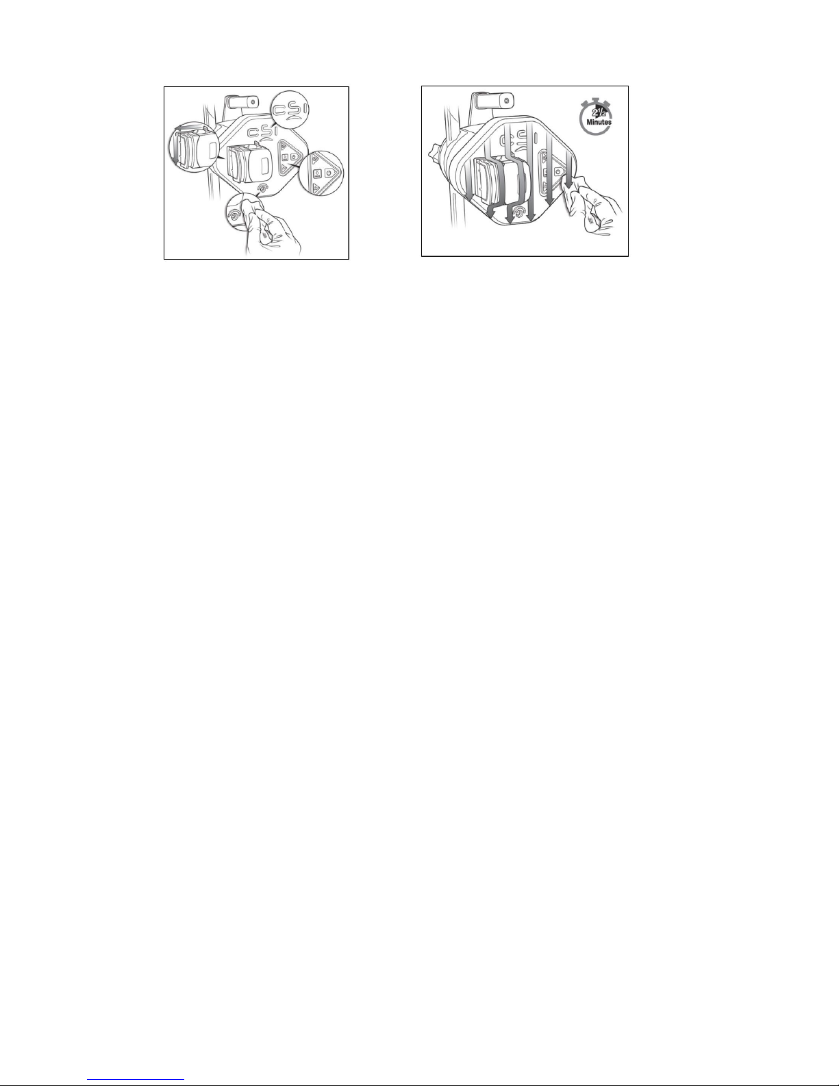
completely covered with solution during the wiping process for a total of 2 ½
minutes to ensure an adequate “dwell” time. Dwell time means the number
of minutes that a product must be in contact with the surface, and remain
wet, in order to assure proper efficacy, or effectiveness to kill organisms.
Surfaces must not become dry at any point during disinfection. Refer to
the following steps for surfaces to be wiped:
a. Open the pump head cover (see Figure 14).
b. Thoroughly wipe the edge of the pump head cover all along the closure
seam on both sides (see Figure 15 and Figure 16 below).
Figure 14. Open pump head cover Figure 15. Wipe closure seam. Figure 16. Wipe Closure Seam
4. Thoroughly wipe the seams and crevices of the pump head cover, around
the edges of the lettering, around the button area, and around the power
outlet (see Figure 17). Thoroughly wipe all surfaces of the front face of the
pump (see Figure 18). Continue to keep all surfaces wet for a minimum of
two and a half minutes. Discard the wipes.
32
Figure 17. Thoroughly wipe these areas Figure 18. Wipe all surfaces of front face
12.5. Returning System Components
Contact CSI Customer Service if system components need to be returned. See the back
of this Instruction for Use for CSI contact information.

33
13. Specifications
13.1. OAD Specifications
Parameter
Value
Electrical cable length:
OAD to OAS pump
3.4 m (11 ft.)
Electrical connector type
(OAD power)
Type CF applied Part –DC barrel
(48 V DC)
Fluid connector type
Polycarbonate Luer fitting
Saline line tubing length
(from pump to OAD port)
3.2 m (10.5 ft.) minimum
Visual alerts
Speed and brake indicators
Sterilization
Ethylene oxide (EtO) cycle
Storage conditions
Room temperature in a clean
environment away from magnets
and sources of electromagnetic
interference (EMI).
Operating conditions
Typical operating
room/catheterization laboratory
environment (10-30°C)
Operating life: Cartridge
8 minutes of total therapy time
Operating life: Handle
24 minutes of total therapy time
Water Ingress Protection
IPX1: Protection against water
ingress
Approximate saline flow
rate for 145 cm (4 Fr) OAD
7 mL/min to 16 mL/min
Approximate saline flow
rate for 145 cm (5 and 6
Fr) OAD
10 mL/min to 30 mL/min
Approximate saline flow
rate for 75 cm (4 Fr) OAD
10 mL/min to 23 mL/min
Approximate saline flow
rate for 200 cm (5 Fr) OAD
10 mL/min to 34 mL/min
Approximate saline flow
rate for 180 cm (5 Fr) OAD
16 mL/min to 35 mL/min

34
OAS Pump Specifications
Parameter
Value
Depth
<30.6 cm (12.0 in)
Height
20.3 cm (8.0 in)
Width
25.4 cm (10.0 in)
Weight
<5.0 kg (11 lbs)
Electrical cable length:
OAS pump to electrical
outlet
6.1 m (20 ft.)
Master Fuse
250 V 4A SLOW BLOW (Type T)
External housing
ABS Plastic
Electrical connector type
(Main Power)
Mains Power Plug (100–240 V AC @
50–60 Hz)
Audible information
signals
Audible information signal for
approximately every 25 sec of OAD
spin time.* Audible information signal
every 5 sec for a total of 30 sec when
the saline level falls below 200 mL
during a treatment period.
Visual alerts
Start button
Low Saline Information Signal when
≤200 mL (± 100 mL) remaining out of
a 1000-mL bag of saline
Storage conditions
Room temperature in a clean
environment.
Operating conditions
Typical operating
room/catheterization laboratory
environment (10-30°C)
Operating life
875 hours minimum, with 350 hours
of therapy minimum or 5 years
Water Ingress Protection
IPX1: Protection against water
ingress
* Timer resets when crown spinning stops.

35
13.2. VIPERWIRE ADVANCE Guide Wire Specifications
VPR-GW 14
VPR-GW-17
VPR-GW-FT14
VPR-FLEX14
VPR-GW-FT18
VPR-FLEX18
VPR-GW-EL-14
VPR-ELFLEX14
VPR-GW-EL18
VPR-ELFLEX18
Guide Wire
Length
335 cm
335 cm
335 cm
335 cm
475 cm
475 cm
Guide Wire
Coating
Silicone
Silicone
Silicone
Silicone
Silicone
Silicone
Core wire
diameter
.014”
.014”
.014”
.014”
.014”
.014”
Core wire
material
Stainless Steel
Stainless Steel
Stainless Steel
Stainless Steel
Stainless Steel
Stainless Steel
Spring Tip
Length
3 cm
3 cm
3 cm
3 cm
3 cm
3 cm
Spring Tip
Diameter
.014”
.017”
.014”
.018”
.014”
.018”
Spring Tip
Material
Platinum/
Tungsten
Platinum/
Tungsten
Platinum/
Tungsten
Platinum/
Tungsten
Platinum/ Tungsten
Platinum/ Tungsten
Spring Tip
Shape
Straight
Straight
Straight
Straight
Straight
Straight
14. OAS Pump Declaration of Conformity
CSI declares that the peripheral system is in conformity with the requirements of: IEC 60601-
1. The OAS pump is compatible for use in a standard catheter laboratory environment.
15. EMC Declaration
Medical electrical equipment needs special precautions regarding electromagnetic
compatibility (EMC). Install and use medical electrical equipment according to the EMC
information below:
• Do not have portable and/or mobile radio-frequency (RF) communications equipment
within close proximity of medical electrical equipment as portable and mobile RF
communications equipment can affect medical electrical equipment.
• Ensure that power frequency magnetic fields are at levels characteristic of a typical
commercial or hospital environment.
• Under an EMC phenomena the OAS may stop operation, and may require user
intervention to recycle the power to resume operation.
The Orbital Atherectomy System has been tested to IEC 60601-1-2. The Orbital Atherectomy
System has been tested to Immunity and Emission Test Levels of a Professional Healthcare

36
Facility Environment. The OAS is Group 1 (Therapy ME Equipment and Systems) and
therefore must meet CISPR 11 Class A. The Orbital Atherectomy System performance may be
impaired by close proximity interference from RFID equipment and other common emitters like:
diathermy, lithotripsy, and electrocautery.
Note: The Emissions characteristics of this equipment make it suitable for use in industrial
areas and hospitals (CISPR 11 class A). If it is used in a residential environment (for which
CISPR 11 class B is normally required) this equipment might not offer adequate protection to
radio-frequency communication services. The user might need to take mitigation measures,
such as relocating or re-orienting the equipment.
Essential Performance of the Exchangeable Product:
• System starts, runs, stops at the operator’s discretion and recovers in a controlled
manner from external upsets.
Emissions
Emissions
Standard
Test
Compliance
Level
Electromagnetic environment Guidance
IEC 60601-1-2
RF Emissions
CISPR 11
Group 1
The orbital atherectomy device
uses RF energy only for its
internal function. Therefore, its
RF emissions are very low and
are not likely to cause any
interference in nearby electronic
equipment.
IEC 60601-1-2
RF Emissions
CISPR 11
Class A
The orbital atherectomy device is
suitable for use in all locations
other than those located in
residential environments and
those directly connected to a
low-voltage power supply
network that supplies buildings
used for domestic purposes.
IEC 60601-1-2
Harmonics, IEC
61000-3-2
Class A
IEC 60601-1-2
Flicker, IEC
61000-3-3
Complies

37
Immunity
Immunity
Standard
Test
Test Level
Compliance Level
IEC 60601-1-2
Electrostatic
Discharge (ESD),
IEC 61000-4-2
±8 kV contact
±2, ±4, ±8, ±15 kV
air
±8 kV contact
±2, ±4, ±8, ±15 kV air
IEC 60601-1-2
Radiated RF, IEC
61000-4-3
3 V/m
80 MHz to 2.7 GHz
3 V/m
80 MHz to 2.7 GHz
IEC 60601-1-2
Radiated RF,
Proximity Fields,
IEC 61000-4-3
Tested to levels
specified in Table 9
of IEC 60601-12:2014
Complies to levels of Table
9
IEC 60601-1-2
Electrical Fast
Transient / Burst,
IEC 61000-4-4
± 2 kV for
power supply
lines
± 1 kV for
input/output
lines
± 2 kV for
power supply
lines
± 1 kV for
input/output
lines
IEC 60601-1-2
Surge, IEC 610004-5
± 2 kV line
to ground
± 1 kV line
to line
± 2 kV line
to ground
± 1 kV line
to line
IEC 60601-1-2
Conducted
Disturbances RF,
IEC 61000-4-6
3 Vrms 150 kHz to
80 MHz
6 Vrms ISM bands
3 Vrms 150 kHz to 80 MHz
6 Vrms ISM bands
IEC 60601-1-2
Power Frequency
50/60 Hz Magnetic
Field, IEC 61000-48
30 A/m, 50 / 60 Hz
30 A/m, 50 and 60 Hz
IEC 60601-1-2
Voltage Dips and
Interruptions, IEC
61000-4-11
100 % dip for 0.5
cycle; 0°, 45°, 90°,
135°, 180°, 225°,
270°, 315°
100% dip for 1
cycle
30% dip for 25
cycles
100% dip for 5
seconds
100% dip for 0.5
cycle; 0°, 45°, 90°, 135°,
180°, 225°, 270°, 315°
100% dip for 1 cycle
30% dip for 25
cycles
100% dip for 5
seconds
AIM 7351731
ISO 14223
65 A/m, 134.2 kHz
65 A/m
AIM 7351731
ISO/IEC 14443-3
(Type A)
7.5 A/m, 13.56
MHz
7.5 A/m
AIM 7351731
ISO/IEC 14443-4
(Type B)
7.5 A/m, 13.56
MHz
7.5 A/m

38
AIM 7351731
ISO/IEC 15693 (ISO
18000-3 Mode 1)
5 A/m, 13.56 MHz
5 A/m
AIM 7351731
ISO 18000-3 Mode
3
12 A/m, 13.56 MHz
12 A/m
AIM 7351731
ISO/IEC 18000-7
3 V/m, 433 MHz
3 V/m
AIM 7351731
ISO/IEC 18000-63
Type C
54 V/m, 860 – 960
MHz
54 V/m
AIM 7351731
ISO/IEC 18000-4
Mode 1
54 V/m, 2.45 GHz
54 V/m
Radio
RFID Transceiver Specifications
FCC ID
2AMME-EX1000
Frequency
13.56 MHz
Receiver bandwidth
14 kHz
Effective Radiated Power
55 mW maximum
Standard
ISO/IEC 15693
Modulation
ASK
16. FCC
This device complies with Part 15 of the FCC Rules. Operation is subject to the following two
conditions: (1) this device may not cause harmful interference, and (2) this device must accept
any interference received, including interference that may cause undesired operation.
Cardiovascular Systems, Inc. has not approved any changes or modifications to this device by
the user. Any changes or modifications to the device could void the user's authority to operate
the equipment.
17. Disclaimer of Warranty
Although Cardiovascular Systems, Inc. (CSI) uses reasonable care in the manufacture of its
devices, they are used in difficult environment within the human body with many biological
differences between individual patients. CSI has no control over the conditions under which
this device is used, condition of the patient, methods of administration or handling after the
device leaves CSI’s possession. THEREFORE, CSI DISCLAIMS ALL WARRANTIES
WHETHER EXPRESSED OR IMPLIED, WRITTEN OR ORAL, INCLUDING BUT NOT
LIMITED TO ANY WARRANTIES OF MERCHANTABILITY OF FITNESS FOR A
PARTICULAR PURPOSE. CSI DOES NOT WARRANT EITHER FOR A GOOD EFFECT OR
AGAINST ALL ILL EFFECT FOLLOWING ITS USE. CSI (INCLUDING ITS AFFILIATED
ENTITIES, OWNERS, DIRECTORS, OFFICERS, EMPLOYEES, AGENTS AND VENDORS)

39
SHALL NOT BE LIABLE FOR ANY DIRECT, INDIRECT, INCIDENTAL OR CONSEQUENTIAL
LOSS, DAMAGE, OR EXPENSE ARISING FROM OR RELATED TO THE USE OF THIS
DEVICE.
No person has authority to bind CSI to any representation, warranty, or liability except as set
forth in this Disclaimer of Warranty.
CSI may, at its sole discretion, replace any device that is determined to have been out of
specification at the time of shipment.
The exclusions, disclaimers, and limitations set forth in this Disclaimer of Warranty are not
intended to, and shall not be construed as to, contravene mandatory provisions of any
applicable law or regulation. If any part of this Disclaimer of Warranty is held to be illegal or
unenforceable by a court of competent jurisdiction, the part shall be modified so as to be
enforceable to the maximum extent possible. If the part cannot be modified, then that part may
be severed and the other parts of this Disclaimer of Warranty shall remain in full force and
effect.

40
Appendix A. System Troubleshooting
If issues with the OAS pump or OAD cannot be resolved in each of the situations below,
replace the recommended part and continue with the procedure. Contact CSI Customer
Service for returning OAS components. See the back of these instructions for use for CSI
contact information.
Issue
number
Issue
Solution
1
The OAS pump will
not power on and no
LEDs are
illuminated on the
OAS pump control
panel
1. Ensure that the power cord is properly inserted into
the power module on the back of the OAS pump and
that the power cord is connected to a functioning wall
power outlet.
2. Ensure that the Master Power switch, on the back of
the OAS pump, is in the on position.
3. Contact CSI Customer Service at the phone number
on the back of this instructions for use to return to
CSI.
2
The OAS pump will
not pump saline
1. Ensure that the OAS pump is properly powered on –
see Issue number 7.
2. Ensure that the saline bag and saline tubing (i.e. bag
spike) are properly connected with no kinks and a
sufficient amount of saline is in the saline bag such
that the low saline level sensor is not active and the
red LED on the OAS pump control panel is not
illuminated.
3. Ensure that the saline tubing is routed correctly
through the OAS pump saline tubing guides and that
the OAS pump saline tubing door is closed.
4. Ensure that the yellow LED is off and the green LED
is illuminated. If the green LED is not illuminated,
press the green Start button and verify that the yellow
LED is off and that the green LED illuminates.
5. If the green LED is flashing while the yellow LED is
illuminated, press the green Start button twice and
verify that the yellow LED is off and that the green
LED illuminates.
6. If the OAS pump does not restart after completing the
above mentioned steps, press the Master Power
switch to power off the OAS pump. Wait a few
seconds and press the Master Power switch to power

41
Issue
number
Issue
Solution
on the OAS pump. Verify that the OAS pump powers
on.
3
The OAS pump was
running, but has
stopped pumping
and the yellow LED
is illuminated
1. Verify the OAD power cord is connected to the OAS
pump.
2. Press the Master Power switch, on the back of the
OAS pump, to power off the OAS pump. Wait five (5)
seconds and press the Master Power switch to
power on the pump.
4
All three LEDs on
the front panel of
the OAS pump
remain illuminated
1. Press the Master Power switch, on the back of the
OAS pump, to power off the OAS pump. Wait a few
seconds and press the Master Power switch to
power on the pump.
2. Contact CSI Customer Service at the phone number
on the back of this instructions for use.
5
After OAS pump
power up, all three
LEDs on the front
panel of the OAS
pump blink three
times and there is
an audible
notification signal
three times.
1. Contact CSI Customer Service at the phone number
on the back of this instructions for use.
6
The low saline level
sensor (red LED) is
illuminated
Note: The OAS pump will stop pumping saline and
supplying power to the OAD 30 seconds after the low
saline level sensor activates while the OAD is
spinning, as indicated by an audible information
signal every 5 seconds.
1. If there is less than 200 mL of saline left in the bag of
saline and lubricant, replace the bag with a new 1000
mL bag of normal saline and lubricant solution.
2. Ensure that the bag of saline and lubricant is hanging
freely from the saline bag open hook and that the low
saline level sensor cord is properly inserted into the
connector on the sensor and the connector on the
back of the OAS pump.
3. Verify that the red low saline LED on the OAS pump
control panel turns off and either the yellow LED or
the green LED illuminates. If the yellow LED

42
Issue
number
Issue
Solution
illuminates, press the Start button on the OAS pump
and verify that the green LED illuminates.
7
OAD speed LED
indicators are
blinking sequentially
(Low, Medium,
High)
1. Verify the cartridge is installed correctly.
2. If the cartridge is installed correctly, replace the
cartridge. If the LEDs continue to blink with the new
cartridge, replace the handle.
8
All OAD Speed
indicator LEDs blink
simultaneously
1. Discontinue treatment.
2. Press the green start button on the OAS pump to turn
off OAD power. Press the green start button on the
OAS pump to supply power to the OAD.
3. If the OAD LEDs continue to blink simultaneously,
replace the OAD.
9
All speed indicator
LEDs on the OAD
handle remain
illuminated
1. Immediately discontinue treatment and replace the
OAD.
10
Blood is backing up
into the OAD
1. Immediately discontinue treatment, but leave the
OAS pump running.
2. Verify that the saline tubing is properly connected to
the saline bag, that the saline tubing is routed
correctly through the OAS pump saline tubing guides,
and that the saline tubing is properly connected to
the OAD.
3. If the saline tubing is properly connected and blood
continues to back into the OAD sheath, replace the
cartridge.
11
The crown does not
spin.
1. Check that the brake is locked and brake LED is
illuminated. Note: the brake does not need to be
locked to use GlideAssist.
2. Verify that the OAS pump and OAD are receiving
power with green LEDs illuminated.
3. Press the OAD on/off button to start device.
4. If the device has power, but does not spin, replace
cartridge.

43
Issue
number
Issue
Solution
12
Crown rotational
speeds are variable
and will not stabilize
1. Immediately discontinue treatment, but leave the
OAS pump running.
2. Verify that saline is flowing. Verify VIPERSLIDE
Lubricant is present in the saline bag. See the
VIPERSLIDE Lubricant Instructions for Use for
information.
3. Verify that the saline tubing is properly connected to
the saline bag, that the saline tubing is routed
correctly through the OAS pump saline tubing guides,
and that the saline tubing is properly connected to
the OAD.
4. Verify that the crown advancer knob moves
smoothly.
5. Retract the crown proximal to the lesion. Using a
travel rate between 1 mm per second and 10 mm per
second, continue treatment on low speed.
6. If rotational speeds will not stabilize, replace the OAD
or guide wire.
13
The crown is not
moving one-to-one
with the crown
advancer knob
During start up in the vessel:
1. Verify the Tuohy valve is not over-tightened.
2. Verify the crown advancer knob moves smoothly.
3. Retract the crown advancer knob until the crown
moves with the knob.
While spinning:
1. Immediately discontinue treatment, but leave the
OAS pump running.
2. Verify the Tuohy valve is not over-tightened.
3. Verify that the crown advancer knob moves
smoothly.
4. Retract the crown advancer knob until the crown
moves with the knob.
5. Verify that contrast media injections were not above
400 psi or occurred during crown spinning.
6. Engage and disengage the lesion using a travel rate
between 1 mm per second and 10 mm per second
while maintaining one-to-one crown to advancer knob
movement.
14
The crown stops
spinning during the
procedure
1. Immediately discontinue treatment, but leave the
OAS pump running.
2. Check to ensure that the OAS pump power cord is
connected to the back of the OAS pump and that the
OAD power cord is connected to the OAS pump.

44
Issue
number
Issue
Solution
3. Check that the OAS pump green LED OAS pump on
light is on and that the OAD green LED light is on. If
the OAS pump green LED is flashing, press the
pump start button twice.
4. Verify that saline is flowing.
5. Check that the OAD guide wire brake lever is in the
down/locked position with brake LED illuminated.
6. Retract the crown proximal to the lesion.
7. Use fluoroscopy to analyze the situation prior to
attempting a low speed orbit of the crown.
15
The OAD will not
exit GlideAssist
mode
1. Press and immediately release any speed button.
2. Cycle power to OAD by pressing the green power
button on the pump.
16
The crown will not
stop spinning
1. Press the power button on the OAS pump.
2. Unplug the OAD from the OAS pump.
3. Unplug the OAS pump from the power source.
17
Unable to load a
guidewire through
the proximal end of
the OAD
1. Ensure the brake is not engaged.
2. Verify the guidewire is <0.014” diameter.
3. Use a 4 French dilator to assist with loading the
guidewire.

45
Appendix B. Introducer, Guide Sheath, or Guide Catheter Size
Table B1. Micro Crown
Crown
Diameter
mm
Model Number
Orbital Atherectomy
Device Maximum
Outer Diameter
mm (inches)
Minimum
Introducer or
Guide Sheath
Internal Diameter,
French (inches)
Guide Catheter
Sizing
1.25
DBP-EX-125MIC145
DBP-CART-125MIC145
1.35 (0.053)
4 (0.053)*
See guide catheter
manufacturer
specifications for
lumen diameter.
1.25
DBP-EX-125MIC145
DBP-CART-125MIC145
1.32 (0.052)
4 (0.053)*
See guide catheter
manufacturer
specifications for
lumen diameter.
* For manual contrast injection with use introducer sheath > 4 Fr.
Table B2. Solid Crown
Crown
Diameter
mm
Model Number
Orbital Atherectomy
Device Maximum
Outer Diameter
mm (inches)
Minimum
Introducer or
Guide Sheath
Internal Diameter,
French (inches)
Guide Catheter
Sizing
1.25
DBP-EX-125SOL75
DBP-CART-125SOL75
1.35 (0.053)
4 (0.053)*
See guide catheter
manufacturer
specifications for
lumen diameter.
1.25
DBP-EX-125SOL145
DBP-CART-125SOL145
1.32 (0.052)
4 (0.053)*
See guide catheter
manufacturer
specifications for
lumen diameter.
1.50
DBP-EX-150SOL145
DBP-CART-150SOL145
1.60 (0.063)
5 (0.065)
See guide catheter
manufacturer
specifications for
lumen diameter.
2.00
DBP-EX-200SOL145
DBP-CART-200SOL145
2.00 (0.079)
6 (0.079)
See guide catheter
manufacturer
specifications for
lumen diameter.
1.25
DBP-EX-125SOL200
DBP-CART-125SOL200
1.60 (0.063)
5 (0.065)
See guide catheter
manufacturer
specifications for
lumen diameter.
1.50
DBP-EX-150SOL200
DBP-CART-150SOL200
1.60 (0.063)
5 (0.065)
See guide catheter
manufacturer
specifications for
lumen diameter.

46
1.75
DBP-EX-175SOLID180
DBP-CART-175SOLID180
1.75 (0.069)
5 (0.070)
See guide catheter
manufacturer
specifications for
lumen diameter.
* For manual contrast injection with use introducer sheath > 4 Fr.
Table B3. Classic Crown
Crown
Diameter
mm
Model Number
Orbital Atherectomy
Device Maximum
Outer Diameter
mm (inches)
Minimum
Introducer or
Guide Sheath
Internal Diameter,
French (inches)
Guide Catheter
Sizing
1.50
DBP-EX-150CLA145
DBP-CART-150CLA145
1.60 (0.063)
5 (0.065)
See guide catheter
manufacturer
specifications for
lumen diameter.
2.00
DBP-EX-200CLA145
DBP-CART-200CLA145
2.00 (0.079)
6 (0.079)
See guide catheter
manufacturer
specifications for
lumen diameter.

47
Appendix C. Maximum Orbit and Resulting Lumen Diameter
The following tables show the maximum orbit and resulting lumen diameter for all crown sizes, at
incremental rotational speeds, for 20 passes (approximately 5 min of treatment time). Quantitative
angiography is recommended to determine minimum vessel diameter.
Note: A pass is defined as once out and back across the lesion. Orbit data presented are based on
a 6 cm pass distance at a travel rate of 10 mm per second.
Table C1. Micro Crown Size and Rotational Speed
Model Number
Crown Size
(mm)
Rotational Speed
(rpm)
Max. Lumen
Diameter* (mm)
Average +2 SD
DBP-EX-125MIC145
DBP-CART-125MIC145
1.25
60,000
1.66
90,000
1.73
140,000
1.81
DBP-EX-125MIC75
DBP-CART-125MIC75
1.25
60,000
1.68
90,000
1.85
140,000
2.10
SD = standard deviation
* These lumens are based on in vitro test results at approximately 5 minutes of treatment time (20 passes) at a rate of
approximately 10 mm per second of travel speed. Actual clinical results may vary.
Table C2. Solid Crown Size and Rotational Speed
Model Number
Crown Size (mm)
Rotational Speed
(rpm)
Max. Lumen
Diameter* (mm)
Average +2 SD
DBP-EX-125SOL75
DBP-CART-125SOL75
1.25
60,000
1.95
90,000
2.51
140,000
3.69
DBP-EX-125SOL145
DBP-CART-125SOL145
1.25
60,000
1.89
90,000
2.37
120,000
2.95
DBP-EX-150SOL145
DBP-CART-150SOL145
1.50
60,000
2.05
90,000
2.90
120,000
3.91
DBP-EX-200SOL145
DBP-CART-200SOL145
2.00
60,000
3.18
90,000
4.36
120,000
6.05
DBP-EX-125SOL200
DBP-CART-125SOL200
1.25
60,000
1.97
90,000
2.33
120,000
2.86
DBP-EX-150SOL200
DBP-CART-150SOL200
1.50
60,000
2.44
90,000
2.98
120,000
3.86

48
DBP-EX-175SOLID180
DBP-CART-175SOLID180
1.75
60,000
2.73
90,000
3.52
120,000
4.62
SD = standard deviation
* These lumens are based on in vitro test results at approximately 5 minutes of treatment time (20 passes) at a rate of
approximately 10 mm per second of travel speed. Actual clinical results may vary.
Table C3. Classic Crown Size and Rotational Speed
Model Number
Crown Size (mm)
Rotational Speed
(rpm)
Max. Lumen
Diameter* (mm)
Average +2 SD
DBP-EX-150CLA145
DBP-CART-150CLA145
1.50
60,000
1.82
90,000
2.08
140,000
2.34
DBP-EX-200CLA145
DBP-CART-200CLA145
2.00
60,000
2.44
90,000
2.63
140,000
2.95
SD = standard deviation
* These lumens are based on in vitro test results at approximately 5 minutes of treatment time (20 passes) at a rate of
approximately 10 mm per second of travel speed. Actual clinical results may vary.

49
Appendix D. Orbit Performance
The following charts demonstrate typical orbit diameter vs. duration of operation (as measured
in simulated calcified lesions.) These charts are for reference only. Actual orbit performance
may vary.
1.25
1.35
1.45
1.55
1.65
1.75
1.85
0 2 4 6 8 10 12 14 16 18 20
Lumen Diameter (mm)
Number of Passes
1.25mm Peripheral Micro Crown Orbit Chart Results
Model DBP-EX-125MIC75 & DBP-CART-125MIC75
LOW SPEED 60Krpm MED SPEED 90Krpm HIGH SPEED 140Krpm

50
1.25
1.35
1.45
1.55
1.65
1.75
1.85
0 2 4 6 8 10 12 14 16 18 20
Lumen Diameter (mm)
Number of Passes
1.25mm Peripheral Micro Crown Orbit Chart Results
Model DBP-EX-125MIC145 & DBP-CART-125MIC145
60k RPM - Low Speed 90k RPM - Medium Speed 140k RPM - High Speed
1.25
1.75
2.25
2.75
3.25
3.75
0 5 10 15 20
Lumen Diameter (mm
)
Number of Passes
1.25mm Peripheral Solid Crown Orbit Chart Results
Model DBP-EX-125SOL75 & DBP-CART-125SOL75
LOW SPEED 60Krpm MED SPEED 90Krpm HIGH SPEED 140Krpm

51
1.25
1.45
1.65
1.85
2.05
2.25
2.45
2.65
2.85
3.05
0 2 4 6 8 10 12 14 16 18 20
Lumen Diameter (mm)
Number of Passes
1.25mm Peripheral Solid Crown Orbit Chart Results
Model DBP-EX-125SOL145 & DBP-CART-125SOL145
60k RPM - Low Speed 90k RPM - Medium Speed 120k RPM - High Speed
1.25
1.75
2.25
2.75
3.25
3.75
0 2 4 6 8 10 12 14 16 18 20
Lumen Diameter (mm)
Number of Passes
1.50mm Peripheral Solid Crown Orbit Chart Results
Model DBP-EX-150SOL145 & DBP-CART-150SOL145
60k RPM Low Speed 90k RPM Medium Speed 120k RPM High Speed

52
2.00
2.50
3.00
3.50
4.00
4.50
5.00
5.50
6.00
0 2 4 6 8 10 12 14 16 18 20
Lumen Diameter (mm)
Number of Passes
2.00mm Peripheral Solid Crown Orbit Chart Results
Model DBP-EX-200SOL145 &DBP-CART-200SOL145
60k RPM Low Speed 90k RPM Medium Speed 120k RPM High Speed
1.50
1.60
1.70
1.80
1.90
2.00
2.10
2.20
2.30
2.40
2.50
0 2 4 6 8 10 12 14 16 18 20
Lumen Diameter (mm)
Number of Passes
1.50mm Peripheral Classic Crown Orbit Chart Results
Model DBP-EX-150CLA145 & DBP-CART-150CLA145
60k RPM Low Speed 90k RPM Medium Speed 140k RPM High Speed

53
2.00
2.10
2.20
2.30
2.40
2.50
2.60
2.70
2.80
2.90
3.00
0 2 4 6 8 10 12 14 16 18 20
Lumen Diameter (mm)
Number of Passes
2.00mm Peripheral Classic Crown Orbit Chart Results
Model DBP-EX-200CLA145 & DBP-CART-200CLA145
LOW SPEED 60Krpm MED SPEED 90Krpm HIGH SPEED 140Krpm
1.25
1.45
1.65
1.85
2.05
2.25
2.45
2.65
2.85
0 2 4 6 8 10 12 14 16 18 20
Lumen Diameter (mm)
Number of Passes
1.25mm Extended Length Diamondback Peripheral Orbit Chart
Results
Model DBP-EX-125SOL200 & DBP-CART-125SOL200
60k RPM - Low Speed 90k RPM - Medium Speed 120k RPM - High Speed

54
1.5
2
2.5
3
3.5
4
0 2 4 6 8 10 12 14 16 18 20
Lumen Diameter (mm)
Number of Passes
1.50mm Extended Length Diamondback Peripheral Orbit Chart
Results
Model DBP-EX-150SOL200 & DBP-CART-150SOL200
60k RPM - Low Speed 90k RPM - Medium Speed 120k RPM - High Speed

Manufacturer:
Cardiovascular Systems, Inc.
1225 Old Highway 8 NW
St. Paul, MN 55112 USA
+01-651-259-1600
+1-877-274-0360 (USA)
© Cardiovascular Systems, Inc. 2018
92-10015-01 Rev B
 Loading...