

Cardin Elettronica 200/BLA24S, 200/BLA24L Instruction Manual

1
AUTOMATION FOR HINGED GATES
ZVL560.00 Mod: 28-11-2014
ENGLISH
24Vdc
Motors
200/BLA24S
200/BLA24L
ATTENTION! Before installing this device read the
following instructions carefully!
Installation example Pag. 2
Assembly Pag. 3-5
Limits of use Pag. 6
Wiring diagrams (installation examples) Pag. 10
Important remarks Pag. 10
User instructions Pag. 10
Installation instructions Pag. 10-11
Electrical connection Pag. 11
Manual release mechanism Pag. 11
Technical specications Pag. 20
Questo prodotto è stato testato e collaudato nei laboratori della casa costruttrice, la quale ne ha verificato la
perfetta corrispondenza delle caratteristiche con quelle richieste dalla normativa vigente. This product has been
tried and tested in the manufacturer's laboratory who have verified that the product conforms in every aspect to the
safety standards in force. Ce produit a été testé et essayé dans les laboratoires du fabriquant. Pour l'installer suivre
attentivement les instructions fournies. Dieses Produkt wurde in den Werkstätten der Herstellerfirma auf die perfekte
Übereinstimmung Übereinstimmung seiner Eigenschaften mit den von den geltenden Normen vorgeschriebenen
Merkmalen getestet und überprüft. Este producto ha sido probado y ensayado en los laboratorios del fabricante, que
ha comprobado la perfecta correspondencia de sus características con las contempladas
por la normativa vigente.
BL
24Vdc
Motors
Model
Date
Instruction manual
Series
BLA
24S-24L
10-09-2014
ZVL560.00
CARDIN ELETTRONICA spa
Via del lavoro, 73 – Z.I. Cimavilla
31013 Codognè (TV) Italy
Tel: +39/0438.404011
Fax: +39/0438.401831
email (Italian): Sales.office.it@cardin.it
email (Europe): Sales.office@cardin.it
Http: www.cardin.it
TECHNICAL SPECIFICATIONS 200/BLA24S 200/BLA24L
Vac 230 230
Vdc 24 24
A 2 2
W 60 60
N 2200 2200
mm 350 500
% 70 70
s 20 25
° 120 120
Mains power supply
Motor power supply
Electrical input
Power input
Thrust
Travel distance (worm screw)
Duty cycle
Opening time 90°
Maximum opening angle
Protection grade IP 44 44
CARDIN ELETTRONICA spa
Via del lavoro, 73 – Z.I. Cimavilla
31013 Codognè (TV) Italy
+39/0438.404011-401818Tel:
Fax:
email (Italian):
email (Europe):
Http:
+39/0438
Sales.office.it@cardin.it
Sales.office@cardin.it
www.cardin.it

2
All rights reserved. Unauthorised copying or use of the information contained in this document is punishable by law
1
4
5
8
11
10
7
6
9
230V-50Hz
3
12
14
13
2
ESEMPIO D'INSTALLAZIONE - INSTALLATION EXAMPLE - EXEMPLE D'INSTALLATION - INSTALLATIONSBEISPIEL - INSTALACIÓN ESTÁNDAR
1
LEGEND
1 Geared motor (SX - left)
2 Geared motor (DX - right)
3 Internal photocells
4 External photocells
5 Warning lights
6 Mechanical selector switch
7 Electric locking device
8 External antenna (RG58 coaxial cable - impedance 50Ω)
9 All-pole circuit breaker with a minimum of 3 mm between the
contacts
10 Mains cable
230 Vac
11 Channelling for the motor connection cable
24 Vdc
12 Channelling route for low voltage wires
13 Electronic programmer
14 Lateral protective photocells (FTCS)
Attention: The drawing is purely indicative and is supplied as working base from which to choose the Cardin electronic components
making up the installation. This drawing therefore does not lay
down any obligations regarding the execution of the installation.

3
2
SCHEMA DI MONTAGGIO
ASSEMBLY DRAWING
SCHÉMA DE MONTAGE
MONTAGEVERFAHREN
ESQUEMA DE MONTAJE
200/BLA24S - 200/BLA24L

4
476 350
137
893
476 500
1043
137
3
SCHEMA DI MONTAGGIO
ASSEMBLY DRAWING
SCHÉMA DE MONTAGE
MONTAGEVERFAHREN
ESQUEMA DE MONTAJE
200/BLA24S - 200/BLA24L
3a
3b
3c
3d

5
105
94
27
Ø8,5
Ø10,5
4
SCHEMA DI MONTAGGIO
ASSEMBLY DRAWING
SCHÉMA DE MONTAGE
MONTAGEVERFAHREN
ESQUEMA DE MONTAJE
200/BLA24S - 200/BLA24L200/BLA24S - 200/BLA24L
4b4a
4c
4d
4e 4f

6
LIMITI D’IMPIEGO - LIMITS OF USE - CONTRAINTES D'UTILISATION - ANWENDUNGSGRENZEN - LIMITES DE EMPLEO
5
C A B, alfa max 90° B, alfa max 100°
80 150 130 < B < 170
90 160 140 < B < 180
100 170 150 < B < 190
110 180 160 < B < 200
120 190 170 < B < 210
130 200 180 < B < 270 270 < B < 285
140 210 190 < B < 260 260 < B < 285
150 220 200 < B < 260 260 < B < 280
160 230 210 < B < 260 260 < B < 265
170 240 220 < B < 260 260 < B < 265
180 250 230 < B < 260 260 < B < 265
190 260 240
200 270 240
1) 200/BLA24L E = 970 mm
C A B, alfa max 90° B, alfa max 120°
80 150 130 < B < 170
90 160 130 < B < 180
100 170 130 < B < 170 170 < B < 210
110 180 130 < B < 180 180 < B < 200
120 190 170 < B < 210 210 < B < 250
130 200 180 < B < 220 220 < B < 250
140 210 190 < B < 220 220 < B < 240
150 220 200 < B < 210
160 230 B < 210
170 240 B < 200
180 250 B < 200
190 260 B < 190
200 270 B < 180
2) 200/BLA24S E = 820 mm
10
2
1
3
BATTUTE DI ARRESTO MECCANICO - MECHANICAL STOP BUFFERS - BUTÉES MÉCANIQUES - MECHANISCHE ENDANSCHLÄGE - TOPES MECÁNICOS
6

7
SCHEMA ELETTRICO IMPIANTO TIPO - STANDARD WIRING DIAGRAM - SCHÉMA ÉLECTRIQUE DE L'EXEMPLE D'INSTALLATION
STANDARD SCHALTPLAN - ESQUEMA ELÉCTRICO INSTALACIÓN ESTÁNDAR
7
PRG900
All rights reserved. Unauthorised copying or use of the information contained in this document is punishable by law
SEL
24V
12V 0
C
1
65432
NA
NC
NC
C
NA
FTC-RX
1
32
CLOSING
COMMON
OPENING
1
32
24V
12V
0
FTC-TX
1
2
1
2
ELS
LP
BRIDGE
CMN
CMN
FTCI (N.C)
TD (N.O)
CMN
TA (N.O)
TC (N.O)
TB (N.C)
LP
CTRL 24Vdc
OUT 24Vdc
7 8 9 10 11 12
13 14 15 16 17
18
19
20 21
22 23 24
LC/CH2
5 6
1 2
M1
CMN
ELS 12V
LS
TAL (N.O)
FTCS (N.C)
B1
P3
1
2
3
J5
Pos.1 Pos.2
1
2
3
CSP (N.C)
3 4
M2
Fuse F4A
Fuse F4A
F3
F1
25
26
27 28
29 30
CMN
FC1
FA1
FC2
FA2
CMN
CMN
F2
15 16 17
CMN
FC1
FA1
181920
FC2
FA2
CMN

10
• These instructions are aimed at professionally qualied "installers of electrical
equipment" and must respect the local standards and regulations in force. All
materials used must be approved and must suit the environment in which the
installation is situated.
• All maintenance operations must be carried out by professionally qualied technicians. Before carrying out any cleaning or maintenance operations make sure the
power is disconnected at the mains.
• This appliance must be used exclusively for the purpose for which it has been
made. "i.e. for the automation of hinged gates" with one or two gate leaves.
• The unit may be tted both to the right and to the left of the passageway. This
product and all its relative components has been designed and manufactured by
Cardin Elettronica who have veried that the product conforms in every aspect
to the safety standards in force. Any non authorised modications are to be
considered improper dangerous and the complete responsibility of the installer.
Caution! mechanical stop buffers must be installed in both the opening and closing positions (pos. 1, 2, 3, g. 7).
It is the responsibility of the installer to make sure that the following public safety
conditions are satised:
1) Ensure that the gate operating installation is far enough away from the main
road to eliminate possible trafc disruptions.
2) The ram must be installed on the inside of the property and not on the public
side of the gate. The gates must not swing outwards onto a public area.
3) The ram is designed for use on gates through which vehicles are passing.
Pedestrians should use a separate entrance.
4) The gate must be in full view when it is operating therefore controls must be
situated in a position where the operator can see the gate at all times.
5) At least two warning signs (similar to the example on the right) should be
placed, where they can be easily seen by the public, in the area of the system
of automatic operation. One inside the property and one on the public side of
the installation. These signs must be indelible and not hidden by any objects
(such as tree branches, decorative fencing etc.).
6) Make sure that the end-user is aware that children and/or
pets must not be allowed to play within the area of a gate
installation. If possible include this in the warning signs.
7) Whenever a fully open gate leaf comes within at least 500
mm of a xed structure the space must be protected by
an anticrush buffer.
8) A correct earth connection is fundamental in order to guarantee the electrical safety of the machine
9) If you have any questions about the safety of the gate operating system, do not
install the ram. Contact your dealer for assistance.
TECHNICAL DESCRIPTION
200/BLA24S Self-locking electromechanical 24 Vdc ram suitable for hinged
gates up to 3 m in length and 150 kg in weight (per gate leaf).
200/BLA24L Self-locking electromechanical 24 Vdc ram suitable for hinged
gates up to 4 m in length and 300 kg in weight per gate leaf (up to 5 m, 300
kg addition of an electric locking device).
- 24 Vdc motor with a steel never ending screw.
- External carter in extruded aluminium.
- Release mechanism components in shockproof plastic.
- Geared motor with steel gears enclosed in a die cast 2-piece aluminium
shell.
- Brackets and accessories in zinc-plated steel.
- Lubrication using permanently uid grease.
ACCESSORIES
206/BLSTA
- Front and rear brackets.
206/BLASR - Adjustable front and rear brackets.
980/XLSE11C - Electric locking device 12 Vac
Attention! Only for EU customers - WEEE marking.
This symbol indicates that once the products life-span has expired
it must be disposed of separately from other rubbish. The user
is therefore obliged to either take the product to a suitable differential collection site for electronic and electrical goods or to
send it back to the manufacturer if the intention is to replace it
with a new equivalent version of the same product.
Suitable differential collection, environmental friendly treatment and disposal
contributes to avoiding negative effects on the ambient and consequently
health as well as favouring the recycling of materials. Illicitly disposing of this
product by the owner is punishable by law and will be dealt with according
to the laws and standards of the individual member nation.
During the opening/closing manoeuvre check for correct operation and activate
the emergency stop button in case of danger.
During blackouts the gate can be released and manually manoeuvred using the
supplied release key (see manual release mechanism).
Periodically check the moving parts for wear and tear and grease if required,
paying particular attention to the never ending screw pos. 13 g. 2, using
lubricants which maintain their friction levels unaltered throughout time and are
suitable for temperatures of -20 to +70°C.
In case of failure or operational anomalies switch off the power at the mains
do not attempt to repair the appliance yourself. Periodically check the correct
operation of all safety devices (photoelectric cells etc.).
Eventual repair work must be carried out by specialised personnel using original
spare parts. The appliance is not suitable for continuous operation and must be
adjusted
according to the model (see technical data on page 20).
The minimum controls which may be installed are OPEN-STOP-CLOSE, these
controls must be installed in a location not accessible to children.
Before starting the installation of the system check that the structure which is
to be automated is in good working order and respects the local standards and
regulations in force.
To this end make sure that the gate is sufciently rigid (if necessary reinforce the
structure) and that the runner guides slide easily.
You are advised to grease all the moving parts using lubricants which maintain
unaltered friction characteristics over a period of time and are suitable for temperatures of -20 to +70°C.
• Check the safety measures between the xed and moving parts:
- a minimum space of 30 mm must always be left along the entire distance
between the gate and the support column measured throughout the entire
opening angle of the gate;
- make sure that the space between the bottom of the gate and the pavement never exceeds 30 mm throughout the entire opening angle of the gate.
• The surface of the gate must not feature openings which allow a person’s
hand or foot to pass through.
• Check the exact positioning of the pivots, and their good working order (the
upper and lower hinges/pivots must be aligned on the same axis).
• Work out the run of the cables according to the command and control devices
tted and make sure the system conforms to the local standard and regulations
in force (see installation example g. 1 pag. 2).
• Check that the appliance is suitable for the size, weight and duty cycle of the
gate to which it is to be applied (see duty cycle on page 20).
BLA24 INSTALLATION
Before reading the installation instructions, take note of the following basic concepts:
- the joint brackets (front and rear) must be mounted correctly at two different
heights;
- the brackets supplied can be welded directly to the structure or secured with
screws and screw anchors, provided the system is able to withstand the forces
imparted: by the actuator, by manual movement of the gate and (in certain conditions) by the wind;
- the position of the brackets establishes the maximum opening angle and the
length of the actuator's linear stroke; consider that the longer the stroke of the
lead screw, the greater the torque and the smoother the movements of the gate
leaf; on the contrary, with a short stroke, movements may be more abrupt and
there will be less torque available. Tables "1" and "2" on page 6 show several
examples of bracket positions; the measurements are only guidelines and should
be used solely to prepare for installation.
APERTURA AUTOMATICA
NON AVVICINARSI
NON PERMETTERE A BAMBINI O AD
ANIMALI DOMESTICI DI SOSTARE NEL
RAGGIO D'AZIONE DEL CANCELLO
ATTENZIONE
IMPORTANT SAFETY INSTRUCTIONS
INSTALLATION INSTRUCTIONS
IMPORTANT REMARKS IMPORTANT REMARKS IMPORTANT REMARKS
READ THE FOLLOWING REMARKS CAREFULLY BEFORE PROCEEDING WITH THE INSTALLATION. PAY PARTICULAR ATTENTION TO ALL THE PARAGRAPHS MARKED WITH THE SYMBOL
NOT READING THESE IMPORTANT INSTRUCTIONS COULD COMPROMISE THE CORRECT WORKING ORDER OF THE SYSTEM AND CREATE DANGER SITUATIONS FOR THE USERS OF THE SYSTEM.
USER INSTRUCTIONS
11
Check which of the possible solutions is applicable to your automation project
and perform a few manual trials before xing the brackets. If necessary use the
adjustable brackets 206/BLASR.
• Start by dening the position of the rear bracket by plotting the values in the tables
horizontally referred to fig. 5. For example: measuring dimension "C" (e.g. 90 mm)
makes it possible to calculate dimensions "A" (e.g. 160 mm) and "B" (from 150 to
190 mm); for other factors, consider that dimension "B" can vary by +/- 20 mm
and dimension "A" can be modied by choosing a different hole in the bracket.
Attention: assess these tolerances well because the more dimensions "A"
and "B" are similar, the smoother the gate jeaf movement will be.
• The rear brackets are supplied in two parts (with non-welded plate) offering the
freedom to: shorten or tilt the bracket or x the drilled bracket directly to the
gate post (figs 4b, 4c). For xing with screw anchors and/or screws the bracket
must be welded to the plate as shown in fig. 4b. Even if the structure of BLA24
is designed to adapt to imperfections or structural deterioration of the xing, the
importance of using maximum precision when levelling the brackets (fig. 4c) cannot
be underestimated.
• The height of the brackets is established easily using a spirit level; the front bracket
must be 27 mm lower (fig. 4d); in addition, calculate the nal height of the actuator
such as to allow correct outlet of the electrical cables or choose a higher position
to reduce the accumulation of dirt, grit and moisture (fig. 4e).
• After having secured the rear bracket and marked the height of the front bracket
proceed as follows:
- secure the actuator as shown in fig. 4f;
- x the front bracket to the actuator;
- move the gate leaf to its fully closed position;
- move the ram to its closed position (a few millimetres before max. extension);
- place the front bracket on the gate leaf and mark the holes.
• Before nal xing (screws or welding) perform a manual opening and closing
movement and check the ram is level (fig. 4e).
The BLA24 Models feature an internal system for mechanical stroke limitation composed of adjustable and independent stop rings (parts 11 and 14 in fig. 2), one for the
opening stroke and one for the closing stroke. To set the stop rings proceed as follows:
- remove the screws (part 6, fig. 2) and remove the cover (part 4, fig. 2).
- t the mechanical stop to the lead screw (fig. 3c) while keeping the xing screws
backed off.
- move the leaf towards the actuator maximum stroke limit and fully tighten the
screws of the mechanical stops
- perform an opening and closing cycle to check the stop rings are correctly posi-
tioned and then ret the actuator cover.
In order to guarantee the correct operation of the appliance you must
use a Cardin direct current electronic programmer available in
the following versions: T624 for one or two motors.
Before connecting the appliance make sure that the voltage rated on the data
plate conforms to that of the mains supply.
• The appliance works off a 24V direct current power supply (see wiring
diagram).
• Do not use cables with aluminium conductors; do not solder the ends of cables
which are to be inserted into the binding posts; use exible multiwire cable
2x1,5 which are marked T min 85°C and are resistant to atmospheric agents.
• The power cable must have enough slack to make sure it is not pulled tight
during normal operation.
• Insert a shunt box (tted with cable clamps) near each motor.
• The power cable must not be wound around any of the appliances components
and must not be cemented into the wall.
• Connect the power cable to the terminal board as shown in gure 7.
IMPORTANT! The geared motor is not tted with a torque limiter. Only use
an electronic programmer which has a torque limiter with maximum force at
the head of the gate equal to 150 N (local standards and regulations in force).
SETTING THE MOTOR TORQUE (see control unit)
When carrying out the installation you are advised to use a Cardin control unit
fitted with a torque limiter.
The Cardin programmers optimise the correct working order of the "machine"
(motorised gates/doors) and guarantee full power maximum thrust at the start of the
opening/closing manoeuvre).
The programmer also guarantees that the effective torque fed to the system will be
that selected by the operator in the control unit. The choice of settings depends
on the weight and
size of the gate leaf/door and the different environmental
conditions on-site.
You are reminded that the standards and regulations in force unequivocally require that the torque be set to a level suitable for the system.
Correctly choosing the torque will guarantee maximum security and long
life for the mechanical components.
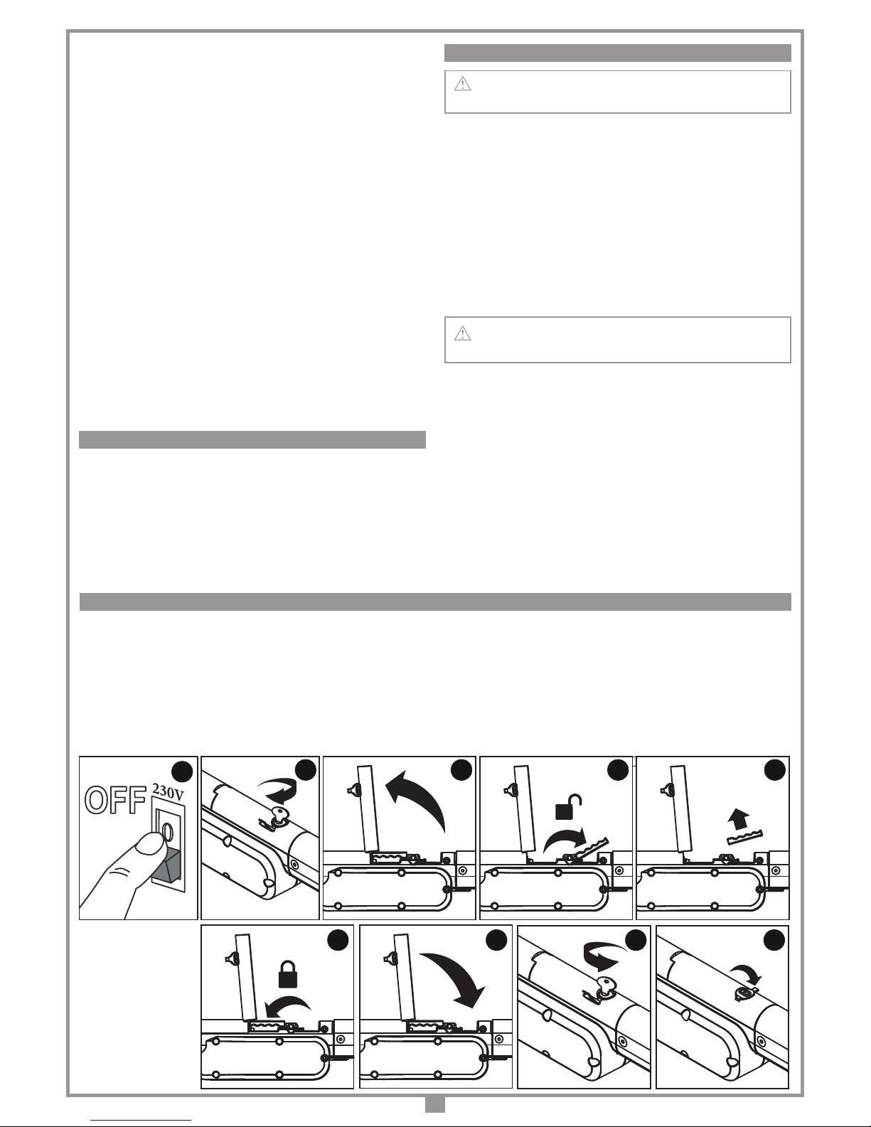
ADJUSTING THE MECHANICAL TRAVEL LIMITS
MANUAL RELEASE AND LOCKING PROCEDURE
1
2 3 4 5
6 7 8 9
Releasing the gate should only be carried out when the motor has stopped so that the gate can be manoeuvred manually during blackouts.
To release the gate use the key supplied with the appliance. It should be stored in a safe and easily reachable place.
Release any electric brakes or locking devices before activating the manual release mechanism.
To release:
1) disconnect the electrical supply; 2) open the rubber cap, insert the key and turn it clockwise; 3) raise cover; 4) turn the lever towards the front of the ram; the gate
leaf can now be moved manually. 5) The gate leaf can remain unlocked and the cover can be retted by simply removing the lever.
To lock:
6) grasp the lever and rotate towards the rear of the ram; at this point the leaf is locked and can only be moved electrically
. 7) After this operation always close
the cover; 8) and turn the key to lock it in place; 9) take care to reclose the rubber cap protecting the lock.
ELECTRICAL CONNECTION
 Loading...