

Cardin Elettronica 200/BL203, 200/BL203L, 200/BL203C, 200/BL203CE, 200/BL352 Instruction Manual
...
CARDIN ELETTRONICA spa
Via del lavoro, 73 – Z.I. Cimavilla
31013 Codognè (TV) Italy
Tel: +39/0438.404011
Fax: +39/0438.401831
email (Italian): Sales.office.it@cardin.it
email (Europe): Sales.office@cardin.it
Http: www.cardin.it
Instruction manual
Questo prodotto è stato testato e collaudato nei laboratori della casa costruttrice, la quale ne ha verificato la
BL
230Vac
Motors
perfetta corrispondenza delle caratteristiche con quelle richieste dalla normativa vigente. This product has been
tried and tested in the manufacturer's laboratory who have verified that the product conforms in every aspect to
the safety standards in force. Ce produit a été testé et essayé dans les laboratoires du fabriquant. Pour l'installer
suivre attentivement les instructions fournies. Dieses Produkt wurde in den Werkstätten der Herstellerfirma
auf die perfekte Übereinstimmung ihrer Eigenschaften mit den von den geltenden Normen vorgeschriebenen
getestet und geprüft. Este producto ha sido probado y ensayado en los laboratorios del fabricante, que ha
comprobado la perfecta correspondencia de sus características con las contempladas
ZVL240.08
Series
BL
Model
Automation 20-07-2005
por la normativa vigente.
AUTOMAZIONE PER CANCELLI A BATTENTE
AUTOMATION FOR HINGED GATES
AUTOMATISME POUR PORTAILS BATTANTS
DREHTORANTRIEBE
AUTOMATIZACION PARA CANCILLAS BATIENTES
Date
ITALIANO
ATTENZIONE! Prima di iniziare l'installazione leggere le
istruzioni attentamente!
230Vac
Motors
200/BL203
200/BL203L
200/BL203C
200/BL203CE
200/BL352
200/BL452
FRANÇAIS
ATTENTION! Avant de commencer la pose, lire
attentivement les instructions!
Exemple d’installation Pag. 2
Montage Pag. 3-6
Dessins du déverrouillage Pag. 6
Fixation de la patte/serrure électrique Pag. 7-8
Schéma électrique (exemple d’installation) Pag. 9-11
Conseils importants Pag. 18
Domaine d'application Pag. 18
Instructions pour l’installation Pag. 19
Branchement électrique Pag. 20
Déverrouillage manuel Pag. 20
Caractéristiques techniques Pag. 28
DEUTSCH
ACHTUNG! Bevor mit der Installation begonnen wird, sollte
die Anleitung aufmerksam gelesen werden!
Esempio d'installazione Pag. 2
Schema di montaggio Pag. 3-6
Disegni di sblocco Pag. 6
Fissaggio staffa/elettroserratura Pag. 7-8
Schema elettrico (impianto tipo) Pag. 9-11
Avvertenze importanti Pag. 12
Istruzioni per l’uso Pag. 12
Istruzione per l’installazione Pag. 13
Collegamento elettrico Pag. 14
Sblocco manuale Pag. 14
Caratteristiche tecniche Pag. 28
ENGLISH ESPAÑOL
ATTENTION! Before installing this device read the following
instructions carefully!
Installation example Pag. 2
Assembly Pag. 3-6
Manual release drawings Pag. 6
Fitting the holding brackets/electric lock Pag. 7-8
Wiring diagrams (installation examples) Pag. 9-11
Important remarks Pag. 15
User instructions Pag. 15
Installation instructions Pag. 16
Electrical connection Pag. 17
Manual release mechanism Pag. 17
Technical specications Pag. 28
ZVL240.08-Mod: 10.06.2013
Anlagenart Seite 2
Montagegearbeiten Seite 3-6
Manuelle Entriegelungs Zeichenen Seite 6
Anbringung Halterbügel/Elektroverriegelung Seite 7-8
Elektrischer Schaltplan (Anlagenart) Seite 9-11
Wichtige Hinweise Seite 21
Betriebsanleitung Seite 21
Anleitungen zur Installation Seite 22
Elektrischer anschluss Seite 23
Manuelle Entriegelung Seite 23
Technische Daten Seite 28
¡ATENCIÓN! Antes de iniciar la instalación del sistema, leer
atentamente las instrucciones.
Instalación estándar Pág. 2
Esquema de montaje Pág. 3-6
Dibujos del dispositivo de desbloqueo Pág. 6
Fijación del soporte/electrocerradura Pág. 7-8
Esquema eléctrico (instalación estándar) Pág. 9-11
Advertencias importantes Pág. 24
Instrucciones para el uso Pág. 24
Instrucciones para la instalación Pág. 25
Conexión eléctrica Pág. 26
Desbloqueo manual Pág. 26
Características técnicas Pág. 28
1
All rights reserved. Unauthorised copying or use of the information contained in this document is punishable by law
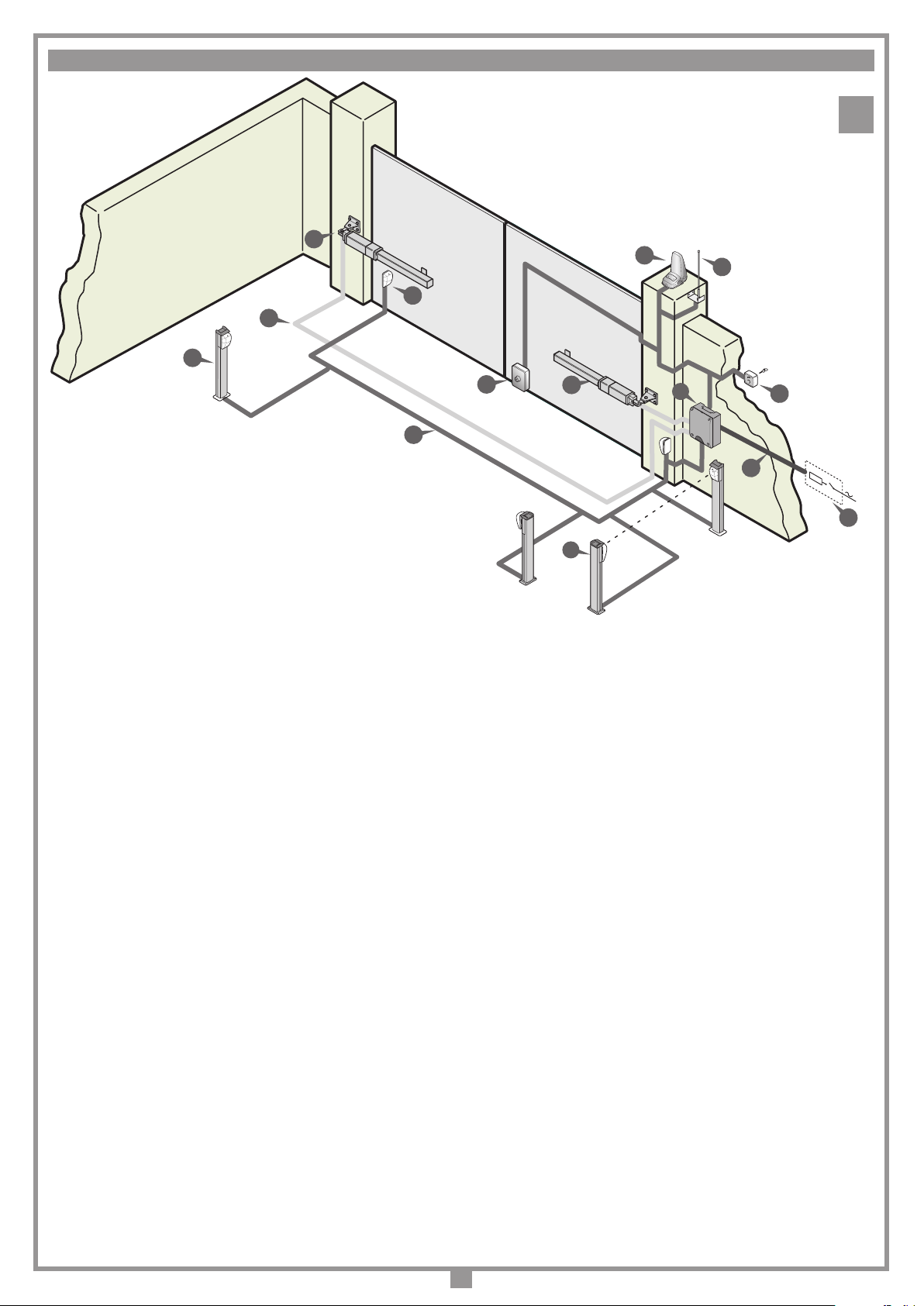
ESEMPIO D'INSTALLAZIONE - INSTALLATION EXAMPLE - EXEMPLE D'INSTALLATION - ANLAGENART - INSTALACIÓN ESTÁNDAR
1
1
5
4
11
3
8
LEGENDA
1 Motoriduttore (SX)
2 Motoriduttore (DX)
3 Fotocellula interna
4 Fotocellula esterna
5 Lampeggiatore
6 Selettore a chiave
7 Elettroserratura
8 Antenna esterna (Cavo coassiale RG58 Impedenza 50Ω)
9 Interruttore onnipolare con apertura contatti min. 3 mm
10 Cavo alimentazione principale 230 Vac
11 Canalatura per collegamenti motori 230 Vac
12 Canalatura per collegamenti a bassa tensione
13 Programmatore elettronico
14 Fotocellule laterali di protezione (FTCS)
Attenzione: Lo schema rappresentato è puramente indicativo e viene fornito
come base di lavoro al ne di consentire una scelta dei componenti elettronici
Cardin da utilizzare. Detto schema non costituisce pertanto vincolo alcuno
per l'esecuzione dell'impianto
LEGEND
1 Geared motor (left)
2 Geared motor (right)
3 Internal photocells
4 External photocells
5 Warning lights
6 Mechanical selector switch
7 Electric locking device
8 External antenna (RG58 coaxial cable - impedance 50Ω)
9 All-pole circuit breaker with a minimum of 3 mm between the contacts
10 Mains cable 230 Vac
11 Channelling for the motor connection cable 230 Vac
12 Channelling route for low voltage wires
13 Electronic programmer
14 Lateral protective photocells (FTCS)
Attention: The drawing is purely indicative and is supplied as working base
from which to choose the Cardin electronic components making up the installation. This drawing therefore does not lay down any obligations regarding
the execution of the installation.
12
7
2
13
6
230V-50Hz
10
9
14
ZEICHENERKLÄRUNG
1 Getriebemotor (SX - links)
2 Getriebemotor (DX - rechts)
3 Interne Lichtschranke
4 Externe Lichtschranke
5 Blinklicht
6 Schlüsselschalter
7 Elektroverriegelung
8 Antenne (Koaxialkabel RG58 Impedanz 50Ω)
9 Allpoliger Schalter mit Kontaktenabstand von mindestens 3 mm
10 Hauptversorgungskabel 230 Vac
11 Kanalverlauf für motorverbindungskabel 230 Vac
12 Kanalverlauf für Anschluss auf Niederspannung
13 Elektronische Steuereinheit
14 Seitliche Schutz-Lichtschranken (FTCS)
Achtung: Bei dem dargestellten Plan handelt es sich nur um ungefähre Angaben und er wird als Arbeitsgrundlage geliefert, um eine Auswahl der zu benutzenden elektronischen Komponenten von Cardin zu erlauben. Der besagte
Plan ist daher für die Ausführung der Anlage nicht bindend.
NOMENCLATURE
1 Motoréducteur (SX - gauche)
2 Motoréducteur (DX - droit)
3 Cellule photoélectrique intérieure
4 Cellule photoélectrique extérieure
5 Clignoteur
6 Sélecteur à clé
7 Serrure électrique
8 Antenne (Câble coaxial RG58 - Impédance 50Ω)
9 Interrupteur omnipolaire avec ouverture des contacts d'au moins 3 mm
10 Câble d’alimentation principale 230 Vac
11 Chemin de câble branchement moteurs 230 Vac
12 Chemin pour branchement basse tension
13 Armoire électronique
14 Cellules photoélectrique latéral de protection (FTCS)
Attention: le schéma, diffusé à titre purement indicatif, est destiné à vous aider
dans le choix des composants électroniques Cardin à utiliser. Par conséquent,
il n'a aucune valeur obligatoire quant à la réalisation de l'installation.
LEYENDA
1 Motorreductor (SX - izquierda)
2 Motorreductor (DX - derecha)
3 Fotocélula interior
4 Fotocélula exterior
5 Relampagueador
6 Selector con llave
7 Electrocerradura
8 Antena exterior (Cable coaxial RG58 Impedancia 50Ω)
9 Interruptor omnipolar con apertura entre los contactos de 3 mm como mín.
10 Cable de alimentación principal 230 Vac
11 Canaleta para el cable del motor 230 Vac
12 Canaleta para el conexionado a baja tensión
13 Centralita electrónica
14 Fotocélulas laterales de protección (FTCS)
Atención: La pantalla que se muestra es sólo indicativa y se suministra como
base de trabajo, con el n de permitir una elección de los componentes electrónicos Cardin por utilizar; en consecuencia, dicho esquema no constituye vínculo
alguno para la ejecución del sistema.
2

1
2
3
4
5
7
8
6
9
10
2
SCHEMA DI MONTAGGIO
ASSEMBLY
MONTAGE
MONTAGEVERFAHREN
ESQUEMA DE MONTAJE
200/BL203 - 200/BL203L - 200/BL352 - 200/BL452
2
SCHEMA DI MONTAGGIO
ASSEMBLY
MONTAGE
MONTAGEVERFAHREN
ESQUEMA DE MONTAJE
200/BL203C - 200/BL203CE
2
3
7
Nota - Note - Hinweis - Remarque - Nota
200/BL352 e 200/BL452 sono privi di sblocco "9"
200/BL352 and 200/BL452 do not feature manual release "9"
200/BL352 et 200/BL452 sont dépourvus de dispositif de déverrouillage "9"
200/BL352 und 200/BL452 besitzen keine Entriegelung «9"
200/BL352 y 200/BL452 están desprovistos de dispositivo de desbloqueo "9"
5
4
11
9
10
3
1
8
6
12
3
1416
80
120
900
1350
80
12
54
90
B
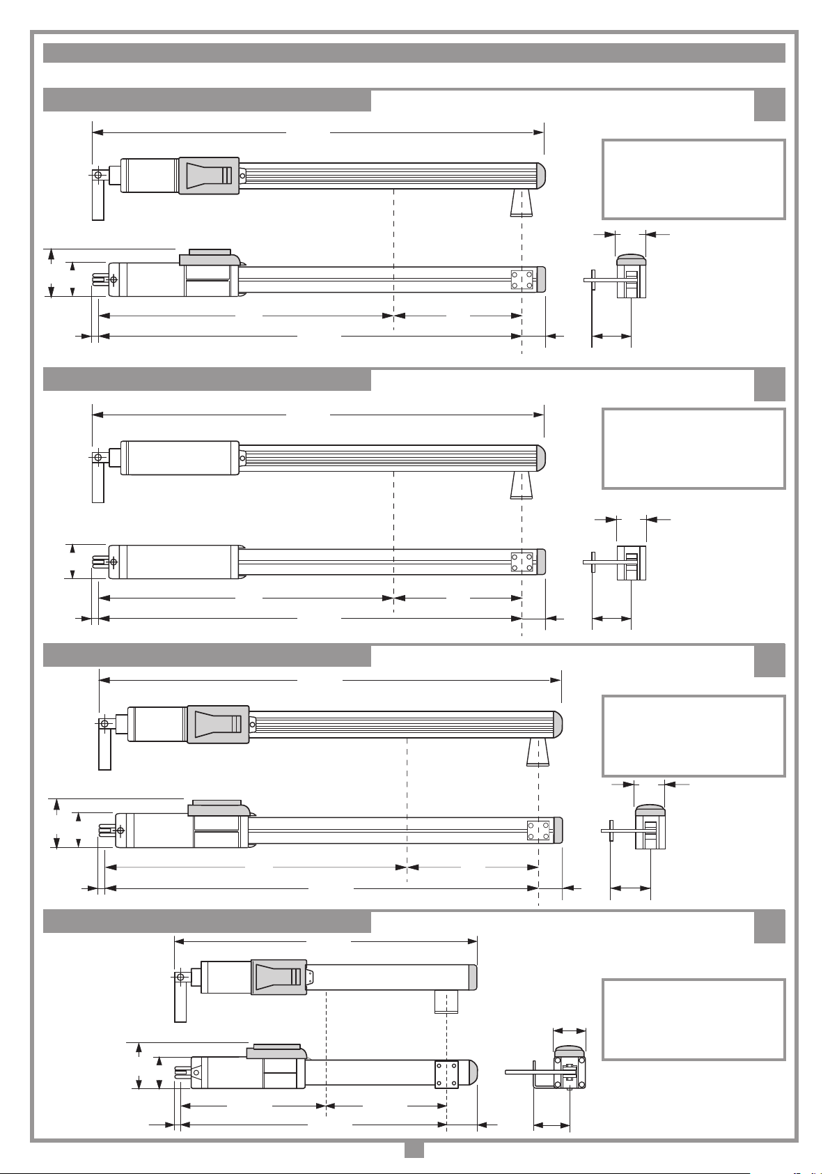
DIMENSIONI D'INGOMBRO - EXTERNAL DIMENSIONS - DIMENSIONS D'ENCOMBREMENT - AUSSENABMESSUNGEN - DIMENSIONES MÁXIMAS
200/BL203
120
80
12
200/BL352 - 200/BL452
725
1076
1005
1096
4
CORSA UTILE "A" = 280 mm
TRAVEL DISTANCE "A" = 280 mm
COURSE UTILE "A" = 280 mm
ARBEITSHUB "A" = 280 mm
CARRERA ÚTIL "A" = 280 mm
80
A
59
90
5
CORSA UTILE "A" = 280 mm
TRAVEL DISTANCE "A" = 280 mm
COURSE UTILE "A" = 280 mm
ARBEITSHUB "A" = 280 mm
CARRERA ÚTIL "A" = 280 mm
80
12
200/BL203L
200/BL203C - 200/BL203CE
745
1025
832
80
A
59
90
6
CORSA UTILE "A" = 450 mm
TRAVEL DISTANCE "A" = 450 mm
COURSE UTILE "A" = 450 mm
ARBEITSHUB "A" = 450 mm
CARRERA ÚTIL "A" = 450 mm
7
12
120
80
390
745
C
CORSA UTILE "C" = 355 mm
TRAVEL DISTANCE "C" = 355 mm
80
75
4
90
COURSE UTILE "C" = 355 mm
ARBEITSHUB "C" = 355 mm
CARRERA ÚTIL "C" = 355 mm
743 max.
D
X
2
A
C
1
B
389 min
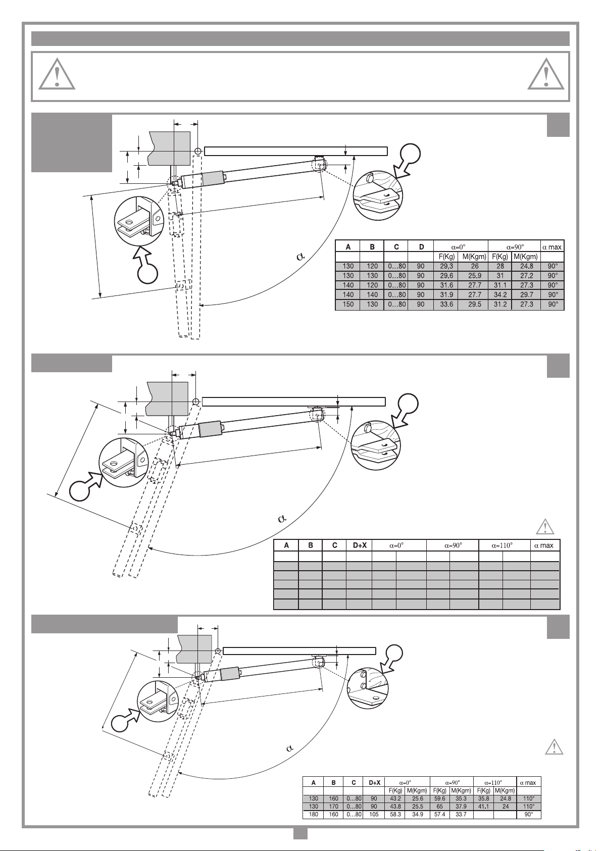
LIMITI D’IMPIEGO - LIMITS OF USE - CONTRAINTES D'UTILISATION - ANWENDUNGSGRENZEN - LIMITES DE EMPLEO
D
1350 max.
X
2
A
C
1
B
905 min
F(Kg) M(Kgm) F(Kg) M(Kgm) F(Kg) M(Kgm)
160 150 0…80 90+20 26,5 32 25.9 31.22 13 15.8 110°
160 180 0…80 90+20 27 31.8 32.5 38.3 19.2 22.6 110°
180 180 0…80 90+20 30 35.3 32.7 38.5 17.7 20.8 110°
180 210 0…80 90+20 30,6 35 39.9 45.7 24.4 28 110°
200 180 0…80 90+20 33 38.8 33 38.8 16 19 110°
Importante! Per un’installazione ottimale utilizzare i dati evidenziati in grigio.
Important! For an optimum installation use the values highlighted in grey.
Important! Pour optimiser l'installation, appliquer les données mises en évidence dans les cases en gris.
Wichtig! Für eine optimale Installation sind die grau markierten Zahlenwerte zu verwenden.
¡Importante! Para una instalación perfecta utilizar los datos evidenciados en gris.
200/BL203
200/BL352
200/BL452
730 min (BL202-202M)
750 min (BL352-452)
200/BL203L
B
C
A
1000 max. (BL203-2024)
1020 max. (BL352-452)
D
2
8
1
9
200/BL203C - BL203CE
X = Spessore da aggiungere a cura dell'installatore
X = Spacer to be added by the installer
X = Cale à ajouter par les soins de l'installateur
X = Vom Installateur hinzuzufügendes Distanzstück
X = Distanciador que el instalador debe añadir
10
X = Spessore da aggiungere a cura dell'installatore
X = Spacer to be added by the installer
X = Cale à ajouter par les soins de l'installateur
X = Vom Installateur hinzuzufügendes Distanzstück
X = Distanciador que el instalador debe añadir
5
ESEMPIO D'INSTALLAZIONE - INSTALLATION EXAMPLE - EXEMPLE D'INSTALLATION - INSTALLATIONSART - EJEMPLO DE INSTALACIÓN
2
1
3
11
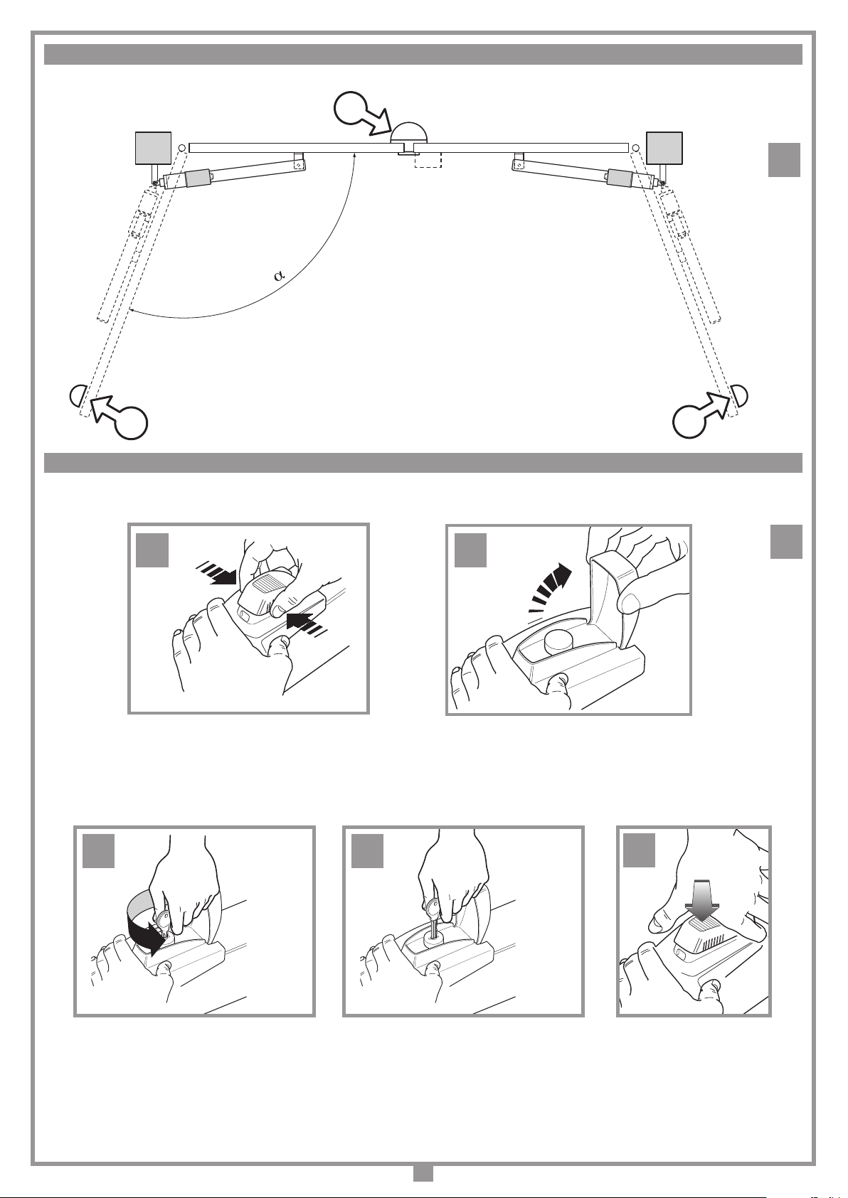
SBLOCCO MANUALE - MANUAL RELEASE - DÉVERROUILLAGE MANUEL - MANUELLE ENTRIEGELUNG - DESBLOQUEO MANUAL
C
A B
D
12
E
6
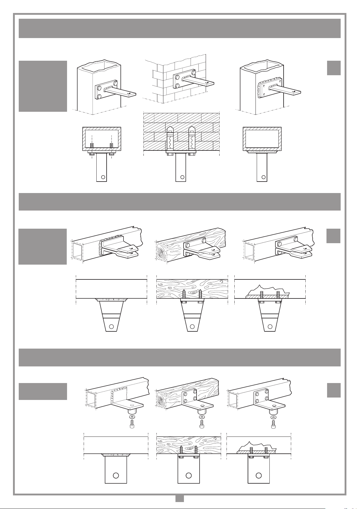
FISSAGGIO STAFFA POSTERIORE (A PILASTRO) - FITTING THE REAR BRACKET (TO A COLUMN) - FIXATION DE LA PATTE POSTÉRIEURE (AU PILIER)
ANBRINGUNG HALTEBÜGEL HINTEN (AN DER SÄULE) - FIJACIÓN DEL SOPORTE POSTERIOR (EN EL PILAR)
200/BL203
200/BL203L
200/BL203C
200/BL203CE
200/BL352
200/BL452
FISSAGGIO STAFFA ANTERIORE (A CANCELLO) - FITTING THE FRONT BRACKET (TO THE GATE) - FIXATION DE LA PATTE ANTÉRIEURE (AU PORTAIL)
ANBRINGUNG HALTEBÜGEL VORNE (AM TOR) - FIJACIÓN DEL SOPORTE ANTERIOR (EN LA CANCILLAS)
200/BL203
200/BL203L
200/BL352
200/BL452
13
14
FISSAGGIO STAFFA ANTERIORE (A CANCELLO) - FITTING THE FRONT BRACKET (TO THE GATE) - FIXATION DE LA PATTE ANTÉRIEURE (AU PORTAIL)
ANBRINGUNG HALTEBÜGEL VORNE (AM TOR) - FIJACIÓN DEL SOPORTE ANTERIOR (EN LA CANCILLAS)
200/BL203C
200/BL203CE
7
15

STAFFA POSTERIORE REGOLABILE (OPZIONALE) - FITTING THE ADJUSTABLE REAR BRACKET (OPTIONAL) - PATTE POSTÉRIEURE
94 min
131 max
20
All rights reserved. Unauthorised copying or use of the information contained in this document is punishable by law
RÉGLABLE (EN OPTION) - HINTERER, EINSTELLBARER HALTEBÜGEL (EXTRA) - SOPORTE POSTERIOR REGULABLE (OPCIONAL)
206/BL201STAP
STAFFA ANTERIORE REGOLABILE (OPZIONALE) - FITTING THE ADJUSTABLE FRONT BRACKET (OPTIONAL) - PATTE ANTÉRIEURE
RÉGLABLE (EN OPTION) - VORNER, EINSTELLBARER HALTEBÜGEL (EXTRA) - SOPORTE ANTERIOR REGULABLE (OPCIONAL)
16
206/BL201SUAR
PREINSTALLAZIONE STAFFA POSTERIORE/ANTERIORE - PRE-INSTALLATION FRONT/REAR BRACKET
PRÉINSTALLATION PATTE POSTÉRIEURE/ANTÉRIEURE - VORMONTAGE HINTERER/VORNER HALTEBÜGEL
200/BL203C - 200/BL203CE
PREINSTALACIÓN SOPORTE POSTERIOR/ANTERIOR
17
18
STAFFA POSTERIORE - REAR BRACKET
PATTE POSTÉRIEURE - HINTERER HALTEBÜGEL
SOPORTE POSTERIOR
41 mm
41 mm
STAFFA ANTERIORE - FRONT BRACKET
PATTE ANTÉRIEURE - VORNER HALTEBÜGEL
SOPORTE ANTERIOR
8
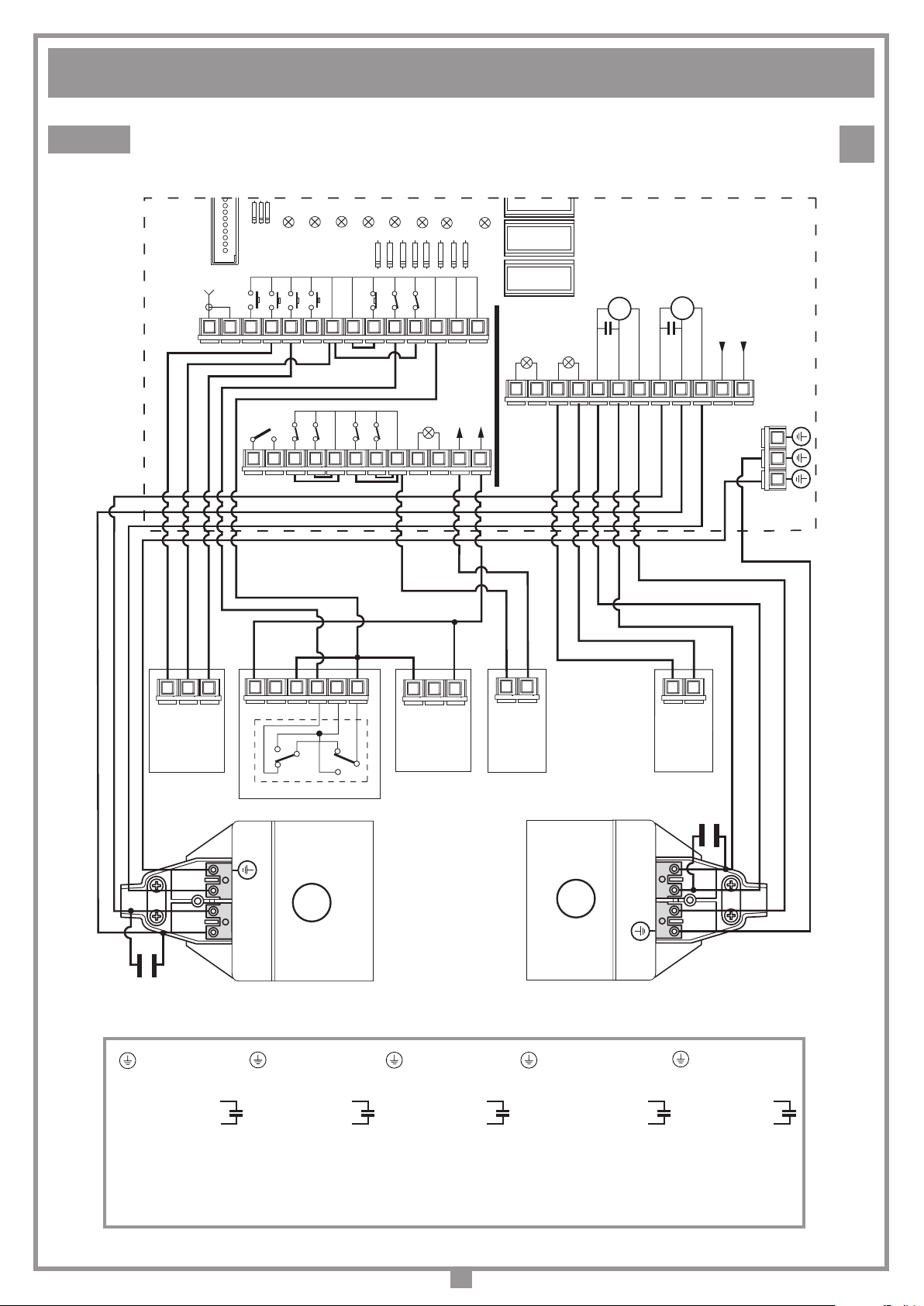
SCHEMA ELETTRICO IMPIANTO TIPO - STANDARD WIRING DIAGRAM - SCHÉMA ÉLECTRIQUE DE L'EXEMPLE D'INSTALLATION
All rights reserved. Unauthorised copying or use of the information contained in this document is punishable by law
ELEKTRISCHER SCHALTPLAN ANLAGENART - ESQUEMA ELÉCTRICO INSTALACIÓN ESTÁNDAR
PRG811
LD3
LD2
LD1
CSER
TAL
TA
ANTENNA
1
TC TD
NA NA NA NA
OUT CH2
NC NC
NAC
PONTICELLI
FCA_1
FCC_1
PONTICELLI
LD4
COMUNE
COMUNE
COMUNE
NC NC
TB
FCA_2
LD5
FCC_2
NC
COMUNE
LD6
FTC_I
NCNC
24V3W
FTC_S
LS
LD7
COMUNE
ELS
12V15W
LD8
COMUNE
COMUNE
141312111098765432
OUT
24V
262524232221201918171615
LC
110-230V~
LP
110-230V~
C
M2
APERTURA
CHIUSURA
COMUNE
C
M1
APERTURA
CHIUSURA
19
230V (EU)
NF
COMUNE
383736353433323130292827
414039
1
OPENING
SEL
32
CLOSING
COMMON
24V
1
12V 0
NA
NC
65432
NA
C
C
NC
1
24V
12V
0
FTC-TX
32
2
ELS
1
2
LP
1
FTC-RX
C2
N
2
M1
M2
3
3
2
N
C1
- Terra
N - Comune
2 - Apre
3 - Chiude
UTILIZZARE PER IL COLLEGAMENTO ELETTRICO CAVO MULTIPOLARE FLESSIBILE 3 x 1 + T
- Ground
N - Neutral
2 - Open
3 - Close
- Terre
N - Commun
2 - Ouvre
3 - Ferme
USE FLEXIBLE MULTIWIRE CABLES FOR THE ELECTRICAL CONNECTION 3 x 1 + EARTH WIRE
POUR LE BRANCHEMENT ÉLECTRIQUE, UTILISER UN CÂBLE MULTIPOLAIRE FLEXIBLE 3 X 1 + T
ZUM ANSCHLUSS EIN MEHRPOLIGES FLEXIBLES ELEKTROKABEL 3 X 1 + T VERWENDEN.
PARA LA CONEXIÓN ELÉCTRICA UTILIZAR UN CABLE MULTIPOLAR FLEXIBLE 3 x 1 + T
- Erdung
N - Gemeinsam
2 - Öffnen
3 - Schließen
- Tierra
N - Común
2 - Abre
3 - Cierra
9
 Loading...