

Cardin Elettronica 200/BL203, 200/BL203L, 200/BL203C, 200/BL203CE, 200/BL352 Instruction Manual
...
CARDIN ELETTRONICA spa
Via del lavoro, 73 – Z.I. Cimavilla
31013 Codognè (TV) Italy
Tel: +39/0438.404011
Fax: +39/0438.401831
email (Italian): Sales.office.it@cardin.it
email (Europe): Sales.office@cardin.it
Http: www.cardin.it
Instruction manual
Questo prodotto è stato testato e collaudato nei laboratori della casa costruttrice, la quale ne ha verificato la
BL
230Vac
Motors
perfetta corrispondenza delle caratteristiche con quelle richieste dalla normativa vigente. This product has been
tried and tested in the manufacturer's laboratory who have verified that the product conforms in every aspect to
the safety standards in force. Ce produit a été testé et essayé dans les laboratoires du fabriquant. Pour l'installer
suivre attentivement les instructions fournies. Dieses Produkt wurde in den Werkstätten der Herstellerfirma
auf die perfekte Übereinstimmung ihrer Eigenschaften mit den von den geltenden Normen vorgeschriebenen
getestet und geprüft. Este producto ha sido probado y ensayado en los laboratorios del fabricante, que ha
comprobado la perfecta correspondencia de sus características con las contempladas
ZVL240.08
Series
BL
Model
Automation 20-07-2005
por la normativa vigente.
AUTOMAZIONE PER CANCELLI A BATTENTE
AUTOMATION FOR HINGED GATES
AUTOMATISME POUR PORTAILS BATTANTS
DREHTORANTRIEBE
AUTOMATIZACION PARA CANCILLAS BATIENTES
Date
ITALIANO
ATTENZIONE! Prima di iniziare l'installazione leggere le
istruzioni attentamente!
230Vac
Motors
200/BL203
200/BL203L
200/BL203C
200/BL203CE
200/BL352
200/BL452
FRANÇAIS
ATTENTION! Avant de commencer la pose, lire
attentivement les instructions!
Exemple d’installation Pag. 2
Montage Pag. 3-6
Dessins du déverrouillage Pag. 6
Fixation de la patte/serrure électrique Pag. 7-8
Schéma électrique (exemple d’installation) Pag. 9-11
Conseils importants Pag. 18
Domaine d'application Pag. 18
Instructions pour l’installation Pag. 19
Branchement électrique Pag. 20
Déverrouillage manuel Pag. 20
Caractéristiques techniques Pag. 28
DEUTSCH
ACHTUNG! Bevor mit der Installation begonnen wird, sollte
die Anleitung aufmerksam gelesen werden!
Esempio d'installazione Pag. 2
Schema di montaggio Pag. 3-6
Disegni di sblocco Pag. 6
Fissaggio staffa/elettroserratura Pag. 7-8
Schema elettrico (impianto tipo) Pag. 9-11
Avvertenze importanti Pag. 12
Istruzioni per l’uso Pag. 12
Istruzione per l’installazione Pag. 13
Collegamento elettrico Pag. 14
Sblocco manuale Pag. 14
Caratteristiche tecniche Pag. 28
ENGLISH ESPAÑOL
ATTENTION! Before installing this device read the following
instructions carefully!
Installation example Pag. 2
Assembly Pag. 3-6
Manual release drawings Pag. 6
Fitting the holding brackets/electric lock Pag. 7-8
Wiring diagrams (installation examples) Pag. 9-11
Important remarks Pag. 15
User instructions Pag. 15
Installation instructions Pag. 16
Electrical connection Pag. 17
Manual release mechanism Pag. 17
Technical specications Pag. 28
ZVL240.08-Mod: 10.06.2013
Anlagenart Seite 2
Montagegearbeiten Seite 3-6
Manuelle Entriegelungs Zeichenen Seite 6
Anbringung Halterbügel/Elektroverriegelung Seite 7-8
Elektrischer Schaltplan (Anlagenart) Seite 9-11
Wichtige Hinweise Seite 21
Betriebsanleitung Seite 21
Anleitungen zur Installation Seite 22
Elektrischer anschluss Seite 23
Manuelle Entriegelung Seite 23
Technische Daten Seite 28
¡ATENCIÓN! Antes de iniciar la instalación del sistema, leer
atentamente las instrucciones.
Instalación estándar Pág. 2
Esquema de montaje Pág. 3-6
Dibujos del dispositivo de desbloqueo Pág. 6
Fijación del soporte/electrocerradura Pág. 7-8
Esquema eléctrico (instalación estándar) Pág. 9-11
Advertencias importantes Pág. 24
Instrucciones para el uso Pág. 24
Instrucciones para la instalación Pág. 25
Conexión eléctrica Pág. 26
Desbloqueo manual Pág. 26
Características técnicas Pág. 28
1
All rights reserved. Unauthorised copying or use of the information contained in this document is punishable by law
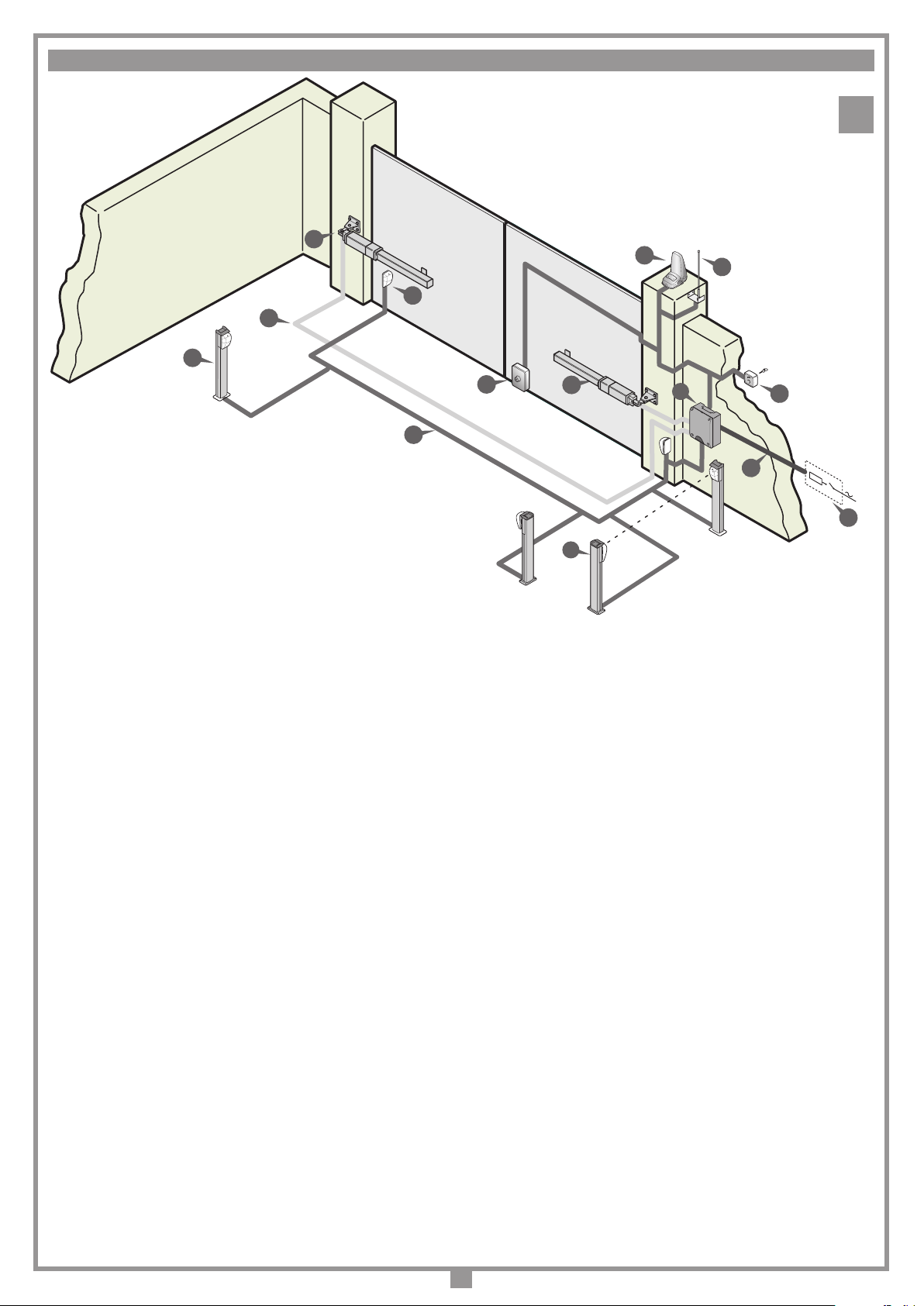
ESEMPIO D'INSTALLAZIONE - INSTALLATION EXAMPLE - EXEMPLE D'INSTALLATION - ANLAGENART - INSTALACIÓN ESTÁNDAR
1
1
5
4
11
3
8
LEGENDA
1 Motoriduttore (SX)
2 Motoriduttore (DX)
3 Fotocellula interna
4 Fotocellula esterna
5 Lampeggiatore
6 Selettore a chiave
7 Elettroserratura
8 Antenna esterna (Cavo coassiale RG58 Impedenza 50Ω)
9 Interruttore onnipolare con apertura contatti min. 3 mm
10 Cavo alimentazione principale 230 Vac
11 Canalatura per collegamenti motori 230 Vac
12 Canalatura per collegamenti a bassa tensione
13 Programmatore elettronico
14 Fotocellule laterali di protezione (FTCS)
Attenzione: Lo schema rappresentato è puramente indicativo e viene fornito
come base di lavoro al ne di consentire una scelta dei componenti elettronici
Cardin da utilizzare. Detto schema non costituisce pertanto vincolo alcuno
per l'esecuzione dell'impianto
LEGEND
1 Geared motor (left)
2 Geared motor (right)
3 Internal photocells
4 External photocells
5 Warning lights
6 Mechanical selector switch
7 Electric locking device
8 External antenna (RG58 coaxial cable - impedance 50Ω)
9 All-pole circuit breaker with a minimum of 3 mm between the contacts
10 Mains cable 230 Vac
11 Channelling for the motor connection cable 230 Vac
12 Channelling route for low voltage wires
13 Electronic programmer
14 Lateral protective photocells (FTCS)
Attention: The drawing is purely indicative and is supplied as working base
from which to choose the Cardin electronic components making up the installation. This drawing therefore does not lay down any obligations regarding
the execution of the installation.
12
7
2
13
6
230V-50Hz
10
9
14
ZEICHENERKLÄRUNG
1 Getriebemotor (SX - links)
2 Getriebemotor (DX - rechts)
3 Interne Lichtschranke
4 Externe Lichtschranke
5 Blinklicht
6 Schlüsselschalter
7 Elektroverriegelung
8 Antenne (Koaxialkabel RG58 Impedanz 50Ω)
9 Allpoliger Schalter mit Kontaktenabstand von mindestens 3 mm
10 Hauptversorgungskabel 230 Vac
11 Kanalverlauf für motorverbindungskabel 230 Vac
12 Kanalverlauf für Anschluss auf Niederspannung
13 Elektronische Steuereinheit
14 Seitliche Schutz-Lichtschranken (FTCS)
Achtung: Bei dem dargestellten Plan handelt es sich nur um ungefähre Angaben und er wird als Arbeitsgrundlage geliefert, um eine Auswahl der zu benutzenden elektronischen Komponenten von Cardin zu erlauben. Der besagte
Plan ist daher für die Ausführung der Anlage nicht bindend.
NOMENCLATURE
1 Motoréducteur (SX - gauche)
2 Motoréducteur (DX - droit)
3 Cellule photoélectrique intérieure
4 Cellule photoélectrique extérieure
5 Clignoteur
6 Sélecteur à clé
7 Serrure électrique
8 Antenne (Câble coaxial RG58 - Impédance 50Ω)
9 Interrupteur omnipolaire avec ouverture des contacts d'au moins 3 mm
10 Câble d’alimentation principale 230 Vac
11 Chemin de câble branchement moteurs 230 Vac
12 Chemin pour branchement basse tension
13 Armoire électronique
14 Cellules photoélectrique latéral de protection (FTCS)
Attention: le schéma, diffusé à titre purement indicatif, est destiné à vous aider
dans le choix des composants électroniques Cardin à utiliser. Par conséquent,
il n'a aucune valeur obligatoire quant à la réalisation de l'installation.
LEYENDA
1 Motorreductor (SX - izquierda)
2 Motorreductor (DX - derecha)
3 Fotocélula interior
4 Fotocélula exterior
5 Relampagueador
6 Selector con llave
7 Electrocerradura
8 Antena exterior (Cable coaxial RG58 Impedancia 50Ω)
9 Interruptor omnipolar con apertura entre los contactos de 3 mm como mín.
10 Cable de alimentación principal 230 Vac
11 Canaleta para el cable del motor 230 Vac
12 Canaleta para el conexionado a baja tensión
13 Centralita electrónica
14 Fotocélulas laterales de protección (FTCS)
Atención: La pantalla que se muestra es sólo indicativa y se suministra como
base de trabajo, con el n de permitir una elección de los componentes electrónicos Cardin por utilizar; en consecuencia, dicho esquema no constituye vínculo
alguno para la ejecución del sistema.
2

1
2
3
4
5
7
8
6
9
10
2
SCHEMA DI MONTAGGIO
ASSEMBLY
MONTAGE
MONTAGEVERFAHREN
ESQUEMA DE MONTAJE
200/BL203 - 200/BL203L - 200/BL352 - 200/BL452
2
SCHEMA DI MONTAGGIO
ASSEMBLY
MONTAGE
MONTAGEVERFAHREN
ESQUEMA DE MONTAJE
200/BL203C - 200/BL203CE
2
3
7
Nota - Note - Hinweis - Remarque - Nota
200/BL352 e 200/BL452 sono privi di sblocco "9"
200/BL352 and 200/BL452 do not feature manual release "9"
200/BL352 et 200/BL452 sont dépourvus de dispositif de déverrouillage "9"
200/BL352 und 200/BL452 besitzen keine Entriegelung «9"
200/BL352 y 200/BL452 están desprovistos de dispositivo de desbloqueo "9"
5
4
11
9
10
3
1
8
6
12
3
1416
80
120
900
1350
80
12
54
90
B
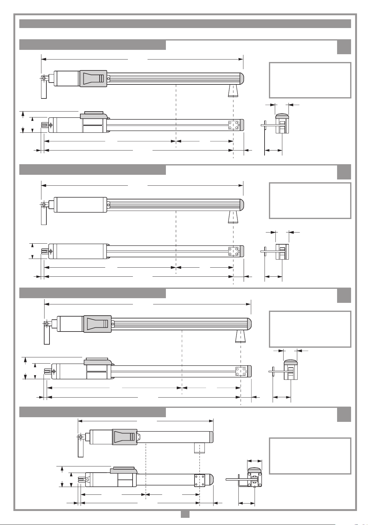
DIMENSIONI D'INGOMBRO - EXTERNAL DIMENSIONS - DIMENSIONS D'ENCOMBREMENT - AUSSENABMESSUNGEN - DIMENSIONES MÁXIMAS
200/BL203
120
80
12
200/BL352 - 200/BL452
725
1076
1005
1096
4
CORSA UTILE "A" = 280 mm
TRAVEL DISTANCE "A" = 280 mm
COURSE UTILE "A" = 280 mm
ARBEITSHUB "A" = 280 mm
CARRERA ÚTIL "A" = 280 mm
80
A
59
90
5
CORSA UTILE "A" = 280 mm
TRAVEL DISTANCE "A" = 280 mm
COURSE UTILE "A" = 280 mm
ARBEITSHUB "A" = 280 mm
CARRERA ÚTIL "A" = 280 mm
80
12
200/BL203L
200/BL203C - 200/BL203CE
745
1025
832
80
A
59
90
6
CORSA UTILE "A" = 450 mm
TRAVEL DISTANCE "A" = 450 mm
COURSE UTILE "A" = 450 mm
ARBEITSHUB "A" = 450 mm
CARRERA ÚTIL "A" = 450 mm
7
12
120
80
390
745
C
CORSA UTILE "C" = 355 mm
TRAVEL DISTANCE "C" = 355 mm
80
75
4
90
COURSE UTILE "C" = 355 mm
ARBEITSHUB "C" = 355 mm
CARRERA ÚTIL "C" = 355 mm
743 max.
D
X
2
A
C
1
B
389 min
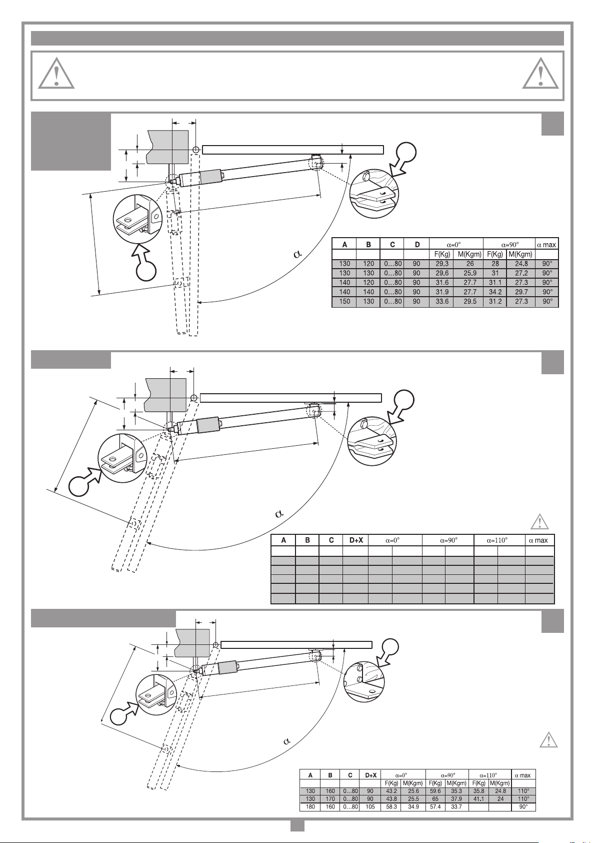
LIMITI D’IMPIEGO - LIMITS OF USE - CONTRAINTES D'UTILISATION - ANWENDUNGSGRENZEN - LIMITES DE EMPLEO
D
1350 max.
X
2
A
C
1
B
905 min
F(Kg) M(Kgm) F(Kg) M(Kgm) F(Kg) M(Kgm)
160 150 0…80 90+20 26,5 32 25.9 31.22 13 15.8 110°
160 180 0…80 90+20 27 31.8 32.5 38.3 19.2 22.6 110°
180 180 0…80 90+20 30 35.3 32.7 38.5 17.7 20.8 110°
180 210 0…80 90+20 30,6 35 39.9 45.7 24.4 28 110°
200 180 0…80 90+20 33 38.8 33 38.8 16 19 110°
Importante! Per un’installazione ottimale utilizzare i dati evidenziati in grigio.
Important! For an optimum installation use the values highlighted in grey.
Important! Pour optimiser l'installation, appliquer les données mises en évidence dans les cases en gris.
Wichtig! Für eine optimale Installation sind die grau markierten Zahlenwerte zu verwenden.
¡Importante! Para una instalación perfecta utilizar los datos evidenciados en gris.
200/BL203
200/BL352
200/BL452
730 min (BL202-202M)
750 min (BL352-452)
200/BL203L
B
C
A
1000 max. (BL203-2024)
1020 max. (BL352-452)
D
2
8
1
9
200/BL203C - BL203CE
X = Spessore da aggiungere a cura dell'installatore
X = Spacer to be added by the installer
X = Cale à ajouter par les soins de l'installateur
X = Vom Installateur hinzuzufügendes Distanzstück
X = Distanciador que el instalador debe añadir
10
X = Spessore da aggiungere a cura dell'installatore
X = Spacer to be added by the installer
X = Cale à ajouter par les soins de l'installateur
X = Vom Installateur hinzuzufügendes Distanzstück
X = Distanciador que el instalador debe añadir
5
ESEMPIO D'INSTALLAZIONE - INSTALLATION EXAMPLE - EXEMPLE D'INSTALLATION - INSTALLATIONSART - EJEMPLO DE INSTALACIÓN
2
1
3
11
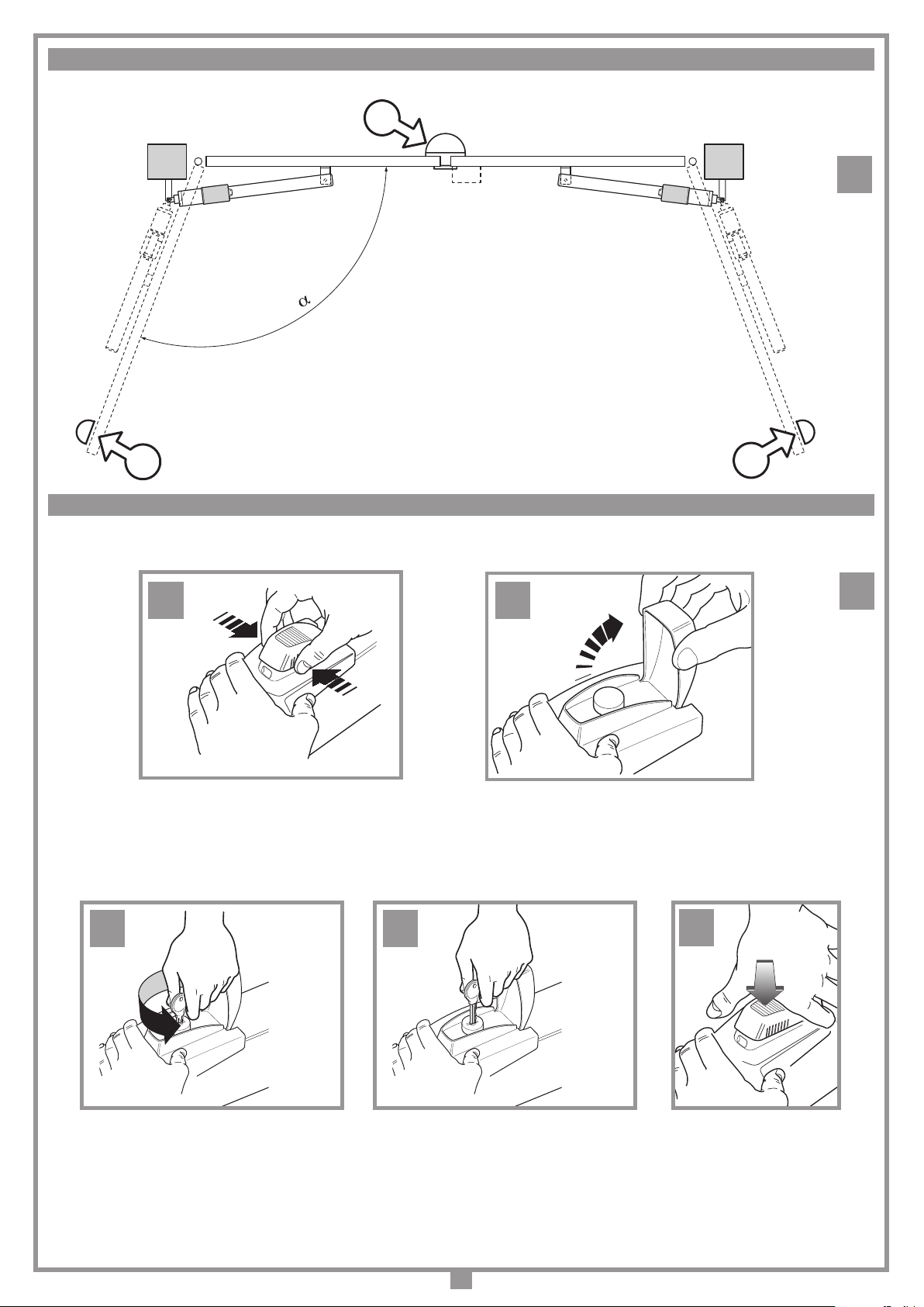
SBLOCCO MANUALE - MANUAL RELEASE - DÉVERROUILLAGE MANUEL - MANUELLE ENTRIEGELUNG - DESBLOQUEO MANUAL
C
A B
D
12
E
6
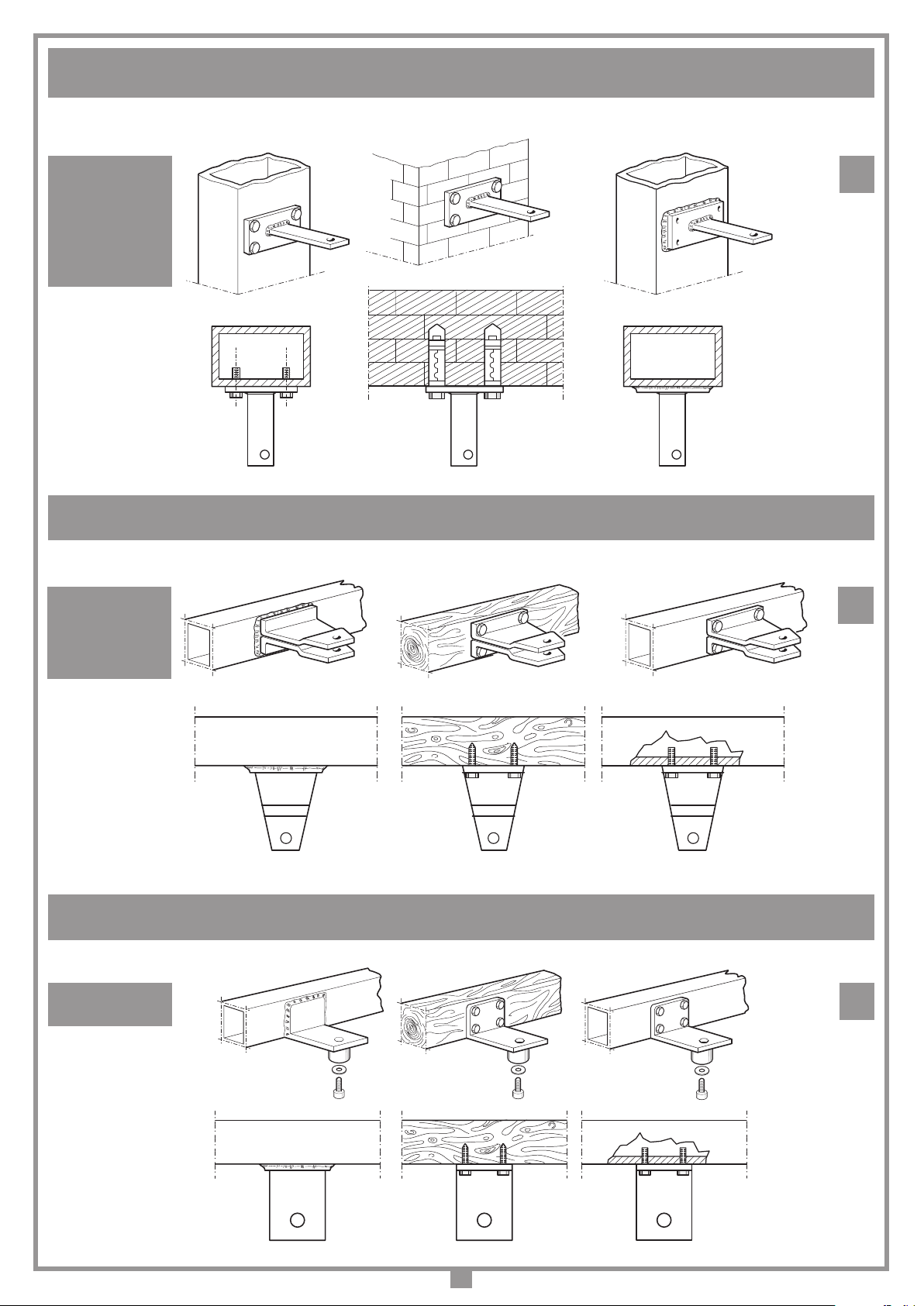
FISSAGGIO STAFFA POSTERIORE (A PILASTRO) - FITTING THE REAR BRACKET (TO A COLUMN) - FIXATION DE LA PATTE POSTÉRIEURE (AU PILIER)
ANBRINGUNG HALTEBÜGEL HINTEN (AN DER SÄULE) - FIJACIÓN DEL SOPORTE POSTERIOR (EN EL PILAR)
200/BL203
200/BL203L
200/BL203C
200/BL203CE
200/BL352
200/BL452
FISSAGGIO STAFFA ANTERIORE (A CANCELLO) - FITTING THE FRONT BRACKET (TO THE GATE) - FIXATION DE LA PATTE ANTÉRIEURE (AU PORTAIL)
ANBRINGUNG HALTEBÜGEL VORNE (AM TOR) - FIJACIÓN DEL SOPORTE ANTERIOR (EN LA CANCILLAS)
200/BL203
200/BL203L
200/BL352
200/BL452
13
14
FISSAGGIO STAFFA ANTERIORE (A CANCELLO) - FITTING THE FRONT BRACKET (TO THE GATE) - FIXATION DE LA PATTE ANTÉRIEURE (AU PORTAIL)
ANBRINGUNG HALTEBÜGEL VORNE (AM TOR) - FIJACIÓN DEL SOPORTE ANTERIOR (EN LA CANCILLAS)
200/BL203C
200/BL203CE
7
15

STAFFA POSTERIORE REGOLABILE (OPZIONALE) - FITTING THE ADJUSTABLE REAR BRACKET (OPTIONAL) - PATTE POSTÉRIEURE
94 min
131 max
20
All rights reserved. Unauthorised copying or use of the information contained in this document is punishable by law
RÉGLABLE (EN OPTION) - HINTERER, EINSTELLBARER HALTEBÜGEL (EXTRA) - SOPORTE POSTERIOR REGULABLE (OPCIONAL)
206/BL201STAP
STAFFA ANTERIORE REGOLABILE (OPZIONALE) - FITTING THE ADJUSTABLE FRONT BRACKET (OPTIONAL) - PATTE ANTÉRIEURE
RÉGLABLE (EN OPTION) - VORNER, EINSTELLBARER HALTEBÜGEL (EXTRA) - SOPORTE ANTERIOR REGULABLE (OPCIONAL)
16
206/BL201SUAR
PREINSTALLAZIONE STAFFA POSTERIORE/ANTERIORE - PRE-INSTALLATION FRONT/REAR BRACKET
PRÉINSTALLATION PATTE POSTÉRIEURE/ANTÉRIEURE - VORMONTAGE HINTERER/VORNER HALTEBÜGEL
200/BL203C - 200/BL203CE
PREINSTALACIÓN SOPORTE POSTERIOR/ANTERIOR
17
18
STAFFA POSTERIORE - REAR BRACKET
PATTE POSTÉRIEURE - HINTERER HALTEBÜGEL
SOPORTE POSTERIOR
41 mm
41 mm
STAFFA ANTERIORE - FRONT BRACKET
PATTE ANTÉRIEURE - VORNER HALTEBÜGEL
SOPORTE ANTERIOR
8
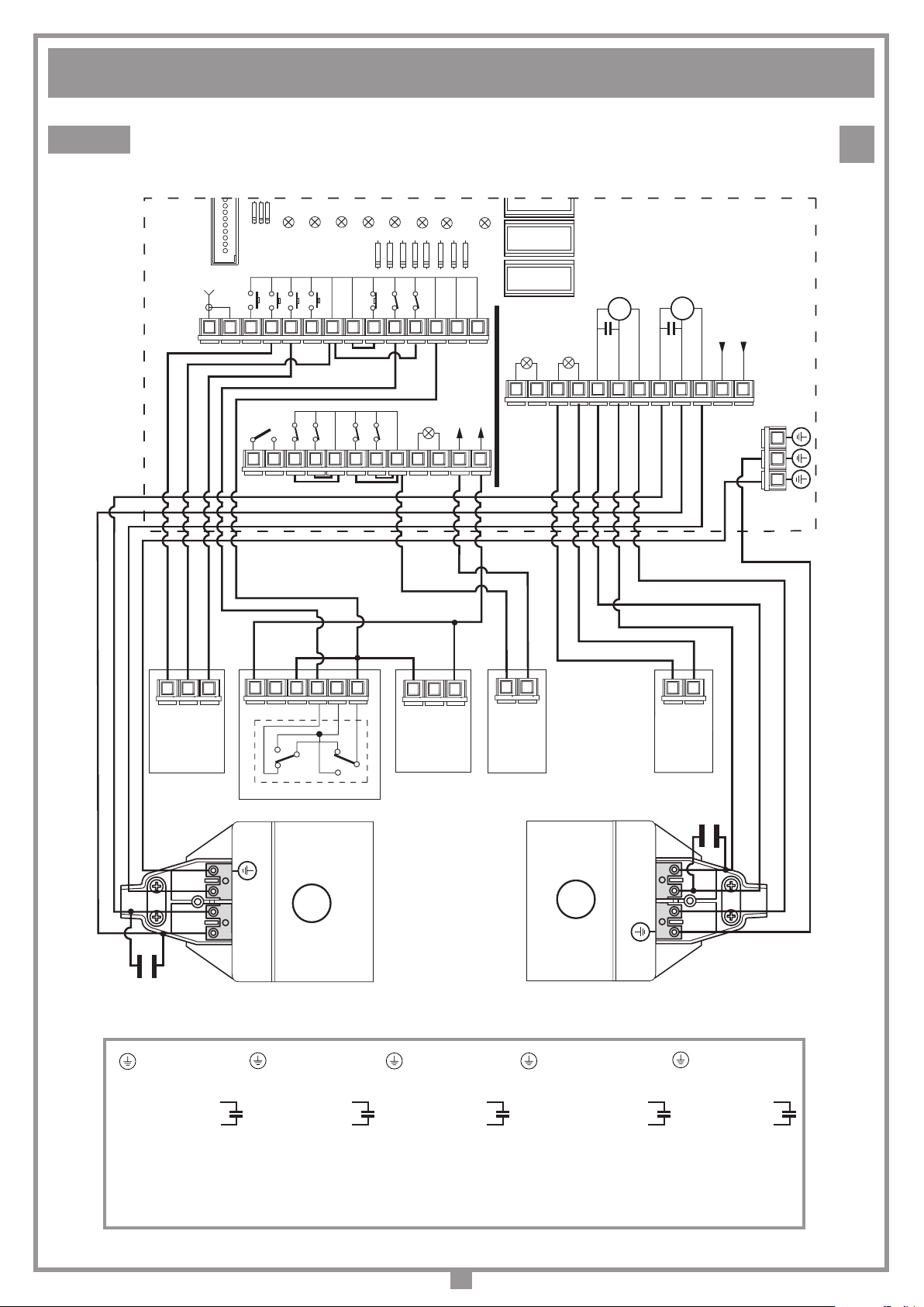
SCHEMA ELETTRICO IMPIANTO TIPO - STANDARD WIRING DIAGRAM - SCHÉMA ÉLECTRIQUE DE L'EXEMPLE D'INSTALLATION
All rights reserved. Unauthorised copying or use of the information contained in this document is punishable by law
ELEKTRISCHER SCHALTPLAN ANLAGENART - ESQUEMA ELÉCTRICO INSTALACIÓN ESTÁNDAR
PRG811
LD3
LD2
LD1
CSER
TAL
TA
ANTENNA
1
TC TD
NA NA NA NA
OUT CH2
NC NC
NAC
PONTICELLI
FCA_1
FCC_1
PONTICELLI
LD4
COMUNE
COMUNE
COMUNE
NC NC
TB
FCA_2
LD5
FCC_2
NC
COMUNE
LD6
FTC_I
NCNC
24V3W
FTC_S
LS
LD7
COMUNE
ELS
12V15W
LD8
COMUNE
COMUNE
141312111098765432
OUT
24V
262524232221201918171615
LC
110-230V~
LP
110-230V~
C
M2
APERTURA
CHIUSURA
COMUNE
C
M1
APERTURA
CHIUSURA
19
230V (EU)
NF
COMUNE
383736353433323130292827
414039
1
OPENING
SEL
32
CLOSING
COMMON
24V
1
12V 0
NA
NC
65432
NA
C
C
NC
1
24V
12V
0
FTC-TX
32
2
ELS
1
2
LP
1
FTC-RX
C2
N
2
M1
M2
3
3
2
N
C1
- Terra
N - Comune
2 - Apre
3 - Chiude
UTILIZZARE PER IL COLLEGAMENTO ELETTRICO CAVO MULTIPOLARE FLESSIBILE 3 x 1 + T
- Ground
N - Neutral
2 - Open
3 - Close
- Terre
N - Commun
2 - Ouvre
3 - Ferme
USE FLEXIBLE MULTIWIRE CABLES FOR THE ELECTRICAL CONNECTION 3 x 1 + EARTH WIRE
POUR LE BRANCHEMENT ÉLECTRIQUE, UTILISER UN CÂBLE MULTIPOLAIRE FLEXIBLE 3 X 1 + T
ZUM ANSCHLUSS EIN MEHRPOLIGES FLEXIBLES ELEKTROKABEL 3 X 1 + T VERWENDEN.
PARA LA CONEXIÓN ELÉCTRICA UTILIZAR UN CABLE MULTIPOLAR FLEXIBLE 3 x 1 + T
- Erdung
N - Gemeinsam
2 - Öffnen
3 - Schließen
- Tierra
N - Común
2 - Abre
3 - Cierra
9

11 12
C
TAL
All rights reserved. Unauthorised copying or use of the information contained in this document is punishable by law
2322212019181716151413
1098765
TD
ANTENNA
TC TA
NC
TB
COMMON
FCA
FCC
COMMON
NO
NO
NO NO
M2
CLOSING
COMMON
OPENING
C
M1
OPENING
COMMON
CLOSING
432
24V
12V 0
C
1
65432
NO
NC
NC
C
NO
1
32
CLOSING
COMMON
OPENING
1
32
24V
12V
0
N
2
3
M1
N
2
3
M2
BRIDGE
1
2
C2
1
2
CLOSING M2
OPENING M2
CLOSING M1
OPENING M1
COMMON
TORQUE LIMIT
Max: 230 Vac
A: 195 Vac
B: 170 Vac
C: 145 Vac
MIN: 120 Vac
M
A
X
A
B
C
M
I
N
COMMON
24V AC
ELS
12V ~
24 25 26 27
28 29 30 31
32
NC NC
FTC_SNCFTC_I
NC
LS
LP
24V
Neutral
Live
LEGEND
TA: OPENING BUTTON
TC: CLOSING BUTTON
TB: BLOCKING BUTTON (bridge if unused)
TD: DYNAMIC BUTTON (open-close)
TAL: LIMITED OPENING
FCC: CLOSING TRAVEL LIMIT (bridge if unused)
FCA: OPENING TRAVEL LIMIT (bridge if unused)
FTC_S: STOP PHOTOCELL (bridge if unused)
FTC_I: INVERTING PHOTOCELL(bridge if unused)
BSP: PASSIVE SAFETY INPUT (bridge if unused)
LP: FLASHING WARNING LIGHTS (24Vac)
LS: INDICATOR LAMP (24Vac)
ELS: ELECTRIC LOCKING DEVICE (12Vac)
NO: NORMALLY OPEN CONTACT
NC: NORMALLY CLOSED CONTACT
C
NO
NC
1
BRIDGE
BSP
NC
FUSE
5A (230V)
10A (110V)
C1
TORQUE LIMITER
Max: 110 Vac
A: 100 Vac
B: 90 Vac
C: 80 Vac
MIN: 70 Vac
230V 50Hz
110V 60Hz
FUSE
5A (230V)
10A (110V)
230V (EEC)
110V (USA)
EUROPE
USA
SEL
FTC-RX
FTC-TX ELS
LP
SCHEMA ELETTRICO IMPIANTO TIPO - STANDARD WIRING DIAGRAM - SCHÉMA ÉLECTRIQUE DE L'EXEMPLE D'INSTALLATION
ELEKTRISCHER SCHALTPLAN ANLAGENART - ESQUEMA ELÉCTRICO INSTALACIÓN ESTÁNDAR
PRG101LSOCE
20
- Terra
N - Comune
2 - Apre
3 - Chiude
UTILIZZARE PER IL COLLEGAMENTO ELETTRICO CAVO MULTIPOLARE FLESSIBILE 3 x 1 + T
- Ground
N - Neutral
2 - Open
3 - Close
- Terre
N - Commun
2 - Ouvre
3 - Ferme
USE FLEXIBLE MULTIWIRE CABLES FOR THE ELECTRICAL CONNECTION 3 x 1 + EARTH WIRE
POUR LE BRANCHEMENT ÉLECTRIQUE, UTILISER UN CÂBLE MULTIPOLAIRE FLEXIBLE 3 X 1 + T
ZUM ANSCHLUSS EIN MEHRPOLIGES FLEXIBLES ELEKTROKABEL 3 X 1 + T VERWENDEN.
PARA LA CONEXIÓN ELÉCTRICA UTILIZAR UN CABLE MULTIPOLAR FLEXIBLE 3 x 1 + T
- Erdung
N - Gemeinsam
2 - Öffnen
3 - Schließen
- Tierra
N - Común
2 - Abre
3 - Cierra
10

All rights reserved. Unauthorised copying or use of the information contained in this document is punishable by law
SCHEMA ELETTRICO IMPIANTO TIPO - STANDARD WIRING DIAGRAM - SCHÉMA ÉLECTRIQUE DE L'EXEMPLE D'INSTALLATION
ELEKTRISCHER SCHALTPLAN ANLAGENART - ESQUEMA ELÉCTRICO INSTALACIÓN ESTÁNDAR
PRG101LSO
LEGEND
TA: OPENING BUTTON
TC: CLOSING BUTTON
TB: BLOCKING BUTTON (bridge if unused)
TD: DYNAMIC BUTTON (open-close)
TAL: LIMITED OPENING
FCC: CLOSING TRAVEL LIMIT (bridge if unused)
FCA: OPENING TRAVEL LIMIT (bridge if unused)
FTC_S: STOP PHOTOCELL (bridge if unused)
FTC_I: INVERTING PHOTOCELL(bridge if unused)
LP: FLASHING WARNING LIGHTS (24Vac)
LS: INDICATOR LAMP (24Vac)
ELS: ELECTRIC LOCKING DEVICE (12Vac)
NO: NORMALLY OPEN CONTACT
NC: NORMALLY CLOSED CONTACT
ANTENNA
FCA
FCC
NC NC
22 23 24 25
COMMON
COMMON
LS
FTC_SNCFTC_I
NC
26 27 28 29
TB
TAL
TD
NC
NO
NO
BRIDGE
LP
24V
30
TC TA
NO NO
COMMON
1817161514131211
24V AC
19
EUROPE
230V 50Hz
Max: 230 Vac
A: 195 Vac
B: 170 Vac
C: 145 Vac
MIN: 120 Vac
ELS12V ~
2120
TORQUE LIMITER
CLOSING M2
C
CLOSING
10
A
B
C
OPENING M2
M2
OPENING
COMMON
X
A
N
I
M
TORQUE LIMIT
M1
C
OPENING
M
OPENING M1
COMMON
CLOSING
56789
4
USA
110V 60Hz
Max: 110 Vac
A: 100 Vac
B: 90 Vac
C: 80 Vac
MIN: 70 Vac
CLOSING M1
FUSE
5A (230V)
10A (110V)
3
Live
N.
12
COMMON
110V (USA)
230V (EEC)
21
1
OPENING
SEL
32
COMMON
CLOSING
24V
1
12V 0
NO
NC
65432
C
NC
NO
NO
C
C
NC
1
32
24V
12V
0
FTC TX ELS
2
1
2
LP
1
FTC RX
C2
M1
N
2
3
3
2
N
M2
C1
- Terra
N - Comune
2 - Apre
3 - Chiude
UTILIZZARE PER IL COLLEGAMENTO ELETTRICO CAVO MULTIPOLARE FLESSIBILE 3 x 1 + T
- Ground
N - Neutral
2 - Open
3 - Close
- Terre
N - Commun
2 - Ouvre
3 - Ferme
USE FLEXIBLE MULTIWIRE CABLES FOR THE ELECTRICAL CONNECTION 3 x 1 + EARTH WIRE
POUR LE BRANCHEMENT ÉLECTRIQUE, UTILISER UN CÂBLE MULTIPOLAIRE FLEXIBLE 3 X 1 + T
ZUM ANSCHLUSS EIN MEHRPOLIGES FLEXIBLES ELEKTROKABEL 3 X 1 + T VERWENDEN.
PARA LA CONEXIÓN ELÉCTRICA UTILIZAR UN CABLE MULTIPOLAR FLEXIBLE 3 x 1 + T
- Erdung
N - Gemeinsam
2 - Öffnen
3 - Schließen
- Tierra
N - Común
2 - Abre
3 - Cierra
11

AVVERTENZE IMPORTANTI AVVERTENZE IMPORTANTI AVVERTENZE IMPORTANTI
LEGGERE ATTENTAMENTE LE SEGUENTI AVVERTENZE PRIMA DI PROCEDERE ALL’INSTALLAZIONE. PRESTARE PARTICOLARE ATTENZIONE A TUTTE LE SEGNALAZIONI DISPOSTE NEL TESTO. IL MANCATO
RISPETTO DI QUESTE POTREBBE COMPROMETTERE IL BUON FUNZIONAMENTO DEL SISTEMA E CREARE
SITUAZIONI DI PERICOLO GRAVE PER L'OPERATORE E GLI UTILIZZATORI DEL SISTEMA STESSO.
• Il presente manuale si rivolge a persone abilitate all'installazione di "apparecchi utilizzatori di energia elettrica" e richiede una buona conoscenza
della tecnica, esercitata in forma professionale e della normativa vigente.
I materiali usati devono essere certicati e risultare idonei alle condizioni
ambientali di installazione.
• Le operazioni di manutenzione devono essere eseguite da personale
qualicato. Prima di eseguire qualsiasi operazione di pulizia o di manutenzione, disinserire l'apparecchiatura dalla rete di alimentazione elettrica.
• Le apparecchiature qui descritte dovranno essere destinate solo all'uso
per il quale sono state espressamente concepite: "La motorizzazione
di cancelli a battente ad una o due ante".
• L'applicazione è possibile sia a sx che a dx della luce passaggio. L'u-
tilizzo dei prodotti e la loro destinazione ad usi diversi da quelli previsti
e/o consigliati, non è stata sperimentata dal costruttore, pertanto i lavori
eseguiti sono sotto la completa responsabilità dell'installatore.
ATTENZIONE! Installare sempre le battute di arresto meccanico
dell’anta (pos 1,2,3 g. 11).
CONSIDERAZIONI GENERALI DI SICUREZZA
È responsabilità dell’installatore vericare le seguenti condizioni di sicurezza:
1) L’installazione deve essere sufcientemente lontana dalla strada in modo
da non costituire pericolo per la circolazione.
2) L’operatore deve essere installato all’interno della proprietà ed il cancello
non deve aprirsi verso l’area pubblica.
3) Il cancello motorizzato è principalmente adibito al passaggio di vetture.
Dove possibile installare per pedoni un ingresso separato.
4) I comandi devono essere posti in vista, ma non entro il raggio d’azione
del cancello. Inoltre quelli installati all’esterno devono essere protetti da
una sicurezza tale da prevenire l’uso non autorizzato.
5) È buona norma segnalare l’automazione con targhe di avvertenza
(simili a quella in gura) che devono essere facilmente visibili. Qualora
l’automazione sia adibita al solo passaggio di veicoli dovranno essere
poste due targhe di avvertenza di divieto di transito
pedonale (una all’interno, una all’esterno).
6) Rendere consapevole l’utente che bambini o animali
domestici non devono giocare o sostare nei pressi
del cancello. Se necessario indicarlo in targa.
7) Qualora l’anta completamente aperta vada ad avvi-
cinarsi ad una struttura ssa lasciando uno spazio
di almeno 500 mm, tale spazio deve essere protetto
con una costa sensibile antischiacciamento.
8) La bontà della connessione di terra dell’apparecchia-
tura è fondamentale ai ni della sicurezza elettrica.
9) È buona norma protegere gli accessi laterali del sistema con coppie di
fotocellule collegate all'ingresso di stop (FTCS), vedi l'esempio d'installazione, componente 14 a pagina 2.
10) Per qualsiasi dubbio a riguardo della sicurezza dell’installazione, non
procedere ma rivolgersi al distributore del prodotto.
DESCRIZIONE TECNICA
200/BL203 Attuatore elettromeccanico autobloccante per ante no a 2
m, 150 kg di peso per anta.
200/BL203L Attuatore elettromeccanico autobloccante per ante no a 2
m, 150 kg di peso per anta. Se utilizzato con la max corsa per aperture
a 90° può essere utilizzato per ante no a 4 m, 150 kg per anta con l'aggiunta di una elettroserratura per garantire il blocco dell'anta in chiusura.
200/BL203C-200/BL203CE Attuatore elettromeccanico autobloccante
per ante no a 1,8 m, 150 kg di peso per anta. Se utilizzato con la max
corsa per aperture a 90° può essere utilizzato per ante no a 3 m, 150
kg per anta con l'aggiunta di una elettroserratura per garantire il blocco
dell'anta in chiusura.
200/BL352 Attuatore elettromeccanico reversibile per ante no a 3,5 m,
300 kg di peso per anta.
200/BL452 Attuatore elettromeccanico reversibile per ante no a 4,5 m,
300 kg di peso per anta.
ATTENZIONE
APERTURA AUTOMATICA
NON AVVICINARSI
NON PERMETTERE A BAMBINI O AD
ANIMALI DOMESTICI DI SOSTARE NEL
RAGGIO D'AZIONE DEL CANCELLO
- Motore monofase montato su calotte in alluminio pressofuso con
protezione termica incorporata.
- Carter di copertura in alluminio estruso.
- Particolari sblocco in plastica antiurto.
- Riduttore con ingranaggi in acciaio racchiusi in semigusci di alluminio
pressofuso (BL203-202L-202C).
- Riduttore epicicloidale ad alta silenziosità e vite senza ne in acciaio
con ricircolo di sfera (BL352-452).
- Staffe e particolari d'aggancio in acciaio zincato.
- Lubricazione a grasso uido permanente.
ACCESSORI
206/BL201STAP - Staffa posteriore a muro regolabile.
206/BL201SUAR - Piatto anteriore regolabile per staffa
attacco cancello.
980/XLSE11C - Elettroserrattura 12Vac.
AVVERTENZE PER L'UTENTE
Attenzione! Solo per clienti dell’EU - Marcatura WEEE.
Il simbolo indica che il prodotto alla ne della propria vita utile deve
essere raccolto separatamente dagli altri riuti. L’utente dovrà
pertanto conferire l’apparecchiatura agli idonei centri di raccolta
differenziata dei riuti elettronici ed elettrici, oppure riconsegnarla
al rivenditore al momento dell’acquisto di una nuova apparecchia-
tura di tipo equivalente, in ragione di uno a uno.
L’adeguata raccolta differenziata per l’avvio al riciclaggio, al trattamento e
allo smaltimento ambientalmente compatibile contribuisce ad evitare possibili
effetti negativi sull’ambiente e sulla salute e favorisce il riciclo dei materiali.
Lo smaltimento abusivo del prodotto da parte del detentore comporta
l’applicazione delle sanzioni amministrative previste dalla normativa vigente
nello Stato Comunitario di appartenenza.
Durante la manovra si deve controllare il movimento del cancello e
azionare il dispositivo di arresto immediato (STOP) in caso di pericolo.
In caso di mancanza di energia elettrica il cancello può essere sbloccato
manualmente utilizzando l'apposita chiave di sblocco in dotazione (vedi
sblocco manuale). Controllare periodicamente lo stato di usura dei perni
ed eventualmente ingrassare le parti in moto in particolare la vite pos. 11
g. 3 (mod. 200/BL203C - 200/BL203CE), usando lubricanti che mantengano uguali caratteristiche di attrito nel tempo e adatti a funzionare
tra -20 e +70°C.
Vericare periodicamente il funzionamento delle sicurezze (fotocellule ecc.)
Le eventuali riparazioni devono essere eseguite da personale specializzato
usando materiali originali e certicati.
L'uso dell'automazione non è idoneo all'azionamento in continuo, bensì
deve essere regolato in base ai vari modelli (vedi caratteristiche tecniche
pagina 28).
ISTRUZIONI PER L'INSTALLAZIONE
I comandi minimi che possono essere installati sono APERTURA-STOPCHIUSURA, tali comandi devono essere posti in un luogo non accessibile a bambini o minori e fuori dal raggio d’azione del cancello. Prima
di procedere all'esecuzione dell'impianto vericare che la struttura da
automatizzare sia in perfetta efcienza nelle sue parti sse e mobili e
realizzata in conformità alla normativa vigente.
A tal ne accertarsi della sufciente rigidità del telo cancello (se necessario
intervenire con rinforzi sulla struttura) e del buon funzionamento dei perni
(si consiglia comunque di lubricare tutte le parti in movimento usando
lubricanti che mantengano uguali caratteristiche di attrito nel tempo e
adatti a funzionare tra -20 e +70°C).
• Controllare i franchi di sicurezza tra parti sse e parti mobili:
- lasciare uno spazio di 30 mm minimo tra il cancello ed il pilastro di
supporto per tutta l’altezza e per tutto l’arco di apertura del cancello;
- assicurarsi che lo spazio tra il cancello ed il pavimento non superi mai
30 mm per tutto l’arco di apertura del cancello.
12

All rights reserved. Unauthorised copying or use of the information contained in this document is punishable by law
• La supercie delle ante non deve presentare aperture tali da permettere
• Fissare con l'apposito perno "1" l'attuatore alla staffa di coda "5" (gura
il passaggio della mano o del piede di persone.
• Controllare l'esatto posizionamento di perni e cerniere, il loro buono
• Portare lo stelo dell'attuatore in estensione no ad arrivare a 5 mm dal
stato di mantenimento e lubricazione (è importante che la cerniera
superiore e quella inferiore siano a piombo tra loro).
• Prevedere il percorso dei cavi secondo le necessità di applicazione dei
dispositivi di comando e sicurezza (ved. impianto tipo g. 1 pag. 2).
• Controllare che l’operatore sia proporzionato alle dimensioni del cancello
e alla frequenza d’uso (intermittenza di lavoro, pag. 28).
FISSAGGIO DEL DISPOSITIVO 200/BL203- BL203L
Il dispositivo può essere ssato sia alla sinistra che alla destra luce
passaggio.
Una corretta installazione deve rispettare la procedura indicata.
• Appoggiare al cancello la staffa di testa "6", contrassegnandone poi la
N.B.: Posizionare l'operatore in perfetta orizzontalità, usando una livella
• La staffa va ssata nei seguenti punti:
- nella struttura portante del cancello o nel fascione trasversale del
• Portare l'anta/e in posizione di chiuso.
• Scegliere il tipo di installazione (g. 8, 9 pag. 5).
• Fissare a pilastro (g. 13 pag. 7) la staffa di coda, rispettando le quote "A"
e "B", dopo aver vericato la posizione della cerniera cancello rispetto
- nel caso mancassero queste possibilità è preferibile ssare al cancello
• Sistemare l'attuatore sulla staffa "6", inserire l'apposito perno "7" e
al pilastro (quota "C" g. 8, 9 pag. 5) e in base al tipo di apertura d'anta
da effettuare.
• Sistemare il carter di protezione ssando le 4 viti posizionate sul riduttore
• Fissare con l'apposito perno "1" l'attuatore alla staffa di coda "5" (g.
2 pag. 3) e col perno "7" alla staffa di testa "6".
• Portare l’anta in apertura no alla battuta meccanica e vericare che
• Portare lo stelo dell'attuatore in estensione no ad arrivare a 5mm dal
completamento della corsa.
• Montare l’elettroserratura per garantire il blocco dell’anta.
2 a pagina 3) e col perno "7" alla staffa di testa "6".
completamento della corsa.
ATTENZIONE! L’interasse tra lo snodo anteriore aggancio staffa di
testa "2" e lo snodo posteriore "1" aggancio staffa di coda non deve
superare mai la misura di 1020 per BL352 e BL452 (vedi g. 8, pag. 5).
posizione.
a bolla d'aria e ssare la staffa di ssaggio anteriore (g. 14 pag. 7).
cancello
una piastra aggiuntiva che servirà poi da piastra di supporto.
bloccare con gli anelli elastici di sicurezza (g. 2 pag. 3).
(pos. 2 g. 2) e ssare il tappo in plastica (pos. 4 g. 2).
lo stelo si trovi a circa 5 mm dalla ne della sua corsa.
ATTENZIONE! L’interasse tra lo snodo anteriore aggancio staffa di
testa "2" e lo snodo posteriore "1" aggancio staffa di coda non deve
superare mai la misura di 1000 mm per il BL203 e 1345 mm per il
BL203L (vedi gure 8-9 a pagina 5).
• Appoggiare al cancello la staffa di testa "6", contrassegnandone poi la
posizione.
N.B.: Posizionare l'operatore in perfetta orizzontalità, usando una livella
a bolla d'aria e ssare la staffa di ssaggio anteriore (g. 14 pag. 7).
• La staffa va ssata nei seguenti punti:
- nella struttura portante del cancello o nel fascione trasversale del cancello;
- nel caso mancassero queste possibilità è preferibile ssare al cancello
una piastra aggiuntiva che servirà poi da piastra di supporto.
• Sistemare l'attuatore sulla staffa "6", inserire l'apposito perno "7" e
bloccare con gli anelli elastici di sicurezza (g. 2 pag. 3).
• Sistemare il carter di protezione ssando le 4 viti posizionate sul riduttore
(pos. 2 g. 2) e ssare il tappo in plastica (pos. 4 g. 2).
• Sempre a motore sbloccato portare l'anta in apertura no alla battuta
meccanica e vericare che lo stelo si trovi a circa 5 mm dalla ne della
sua corsa.
• Nel caso si utilizzi il 200/BL203L per un'anta superiore a 2 m no a 4
m sarà necessaria l'applicazione di un'elettroserratura di blocco per
garantire il blocco dell'anta in chiusura.
FISSAGGIO DEL DISPOSITIVO 200/BL352 - 200/BL452
Il dispositivo può essere ssato sia alla sinistra che alla destra luce
passaggio.
Una corretta installazione deve rispettare la procedura indicata.
• Portare l'anta/e in posizione di chiuso.
• Scegliere il tipo di installazione (g. 8 pag. 5).
• Fissare a pilastro (g. 13 pag. 7) la staffa di coda, rispettando le quote
"A" e "B", dopo aver vericato la posizione della cerniera cancello
rispetto al pilastro (quota "C" g. 8 pag. 5) e in base al tipo di apertura
d'anta da effettuare.
ATTENZIONE! Il motore deve essere montato
sul cancello con i fori scarico condensa
"A" rivolti verso il basso (vedi gura)
FISSAGGIO DEL DISPOSITIVO 200/BL203C-200/BL203CE
Il dispositivo può essere ssato sia alla sinistra che alla destra luce
passaggio.
• Portare l'anta/e in posizione di chiuso.
• Scegliere il tipo di installazione (g. 10 pag. 5).
• Fissare a pilastro (g. 13 pag. 7) la staffa di coda, rispettando le quote
"A" e "B", dopo aver vericato la posizione della cerniera cancello
rispetto al pilastro (quota "C" g. 10 pag. 5) e in base al tipo di apertura
d'anta da effettuare.
Nota: in caso di preinstallazione delle staffe (posteriore ed anteriore)
senza la presenza del pistone, consultare anche le indicazioni in
gura 18.
• Sistemare il carter di protezione "3" (con la rigatura rivolta verso il cancello) ssando le 4 viti "2" posizionate sul riduttore ( serrare a fondo) e
ssare il tappo in plastica "5" con le 4 viti in dotazione (g. 2 pag. 3)
• Far traslare la chiocciola dell'attuatore (part. 4 g. 3) no ad arrivare a
15 mm dal completamento della corsa in chiusura.
• Fissare con l'apposito perno "1" l'attuatore alla staffa di coda "6" (g.
3 pag. 3)
• Portare l'attuatore nella normale posizione di funzionamento appoggiando al cancello la staffa di testa, contrassegnandone poi la posizione.
N.B.: Posizionare l'operatore in perfetta orizzontalità, usando una livella
a bolla d'aria.
- Fissare la staffa di ssaggio anteriore (g. 14 pag. 7).
• La staffa va ssata nei seguenti punti:
- nella struttura portante del cancello o nel fascione trasversale del
cancello;
- nel caso mancassero queste possibilità è preferibile ssare al cancello
una piastra aggiuntiva che servirà poi da piastra di supporto.
• Inserire il perno della chiocciola "4" nell'apposito foro della staffa "9"
e bloccare con la vite e rondella "8" (g. 3 pag. 3).
• Sbloccare l'attuatore e portare l'anta in apertura e vericare l'esatto
funzionamento di tutti gli elementi.
• Nel caso si utilizzi il 200/BL203C - 200/BL203CE per un'anta superiore
a 1,8 m no a 3 m sarà necessaria l'applicazione di un'elettroserratura
di blocco per garantire il blocco dell'anta in chiusura.
A
13

COLLEGAMENTO ELETTRICO (fig. 19-21 pag. 9-11)
Assicurarsi prima di allacciare l'apparecchiatura che la tensione e la frequenza di rete corrisponda ai valori riportati nella targhetta caratteristiche.
• L'apparecchiatura funziona con tensione monofase 230 V 50 Hz (vedi
schema elettrico)
• Il motoriduttore deve essere collegato ad un efcace impianto di messa
a terra, pertanto utilizzare il morsetto contrassegnato con il simbolo
che si trova sulla scatola porta morsettiera.
• Non utilizzare cavo con conduttori in alluminio; non stagnare l’estremità
dei cavi da inserire in morsettiera; utilizzare cavo con marcatura T min
85°C resistente agli agenti atmosferici.
• Il cavo di alimentazione del motore deve fare un percorso ampio tale da
non risultare teso in alcun punto.
• Il cavo non deve essere arrotolato intorno a supporti, non deve essere
cementato nel muro.
Tra la centralina di comando e la rete deve essere interposto
un interruttore onnipolare con distanza di apertura tra i contatti di
almeno 3 mm.
L'operazione di sblocco va fatta solamente a motore fermo, per mancanza
di energia elettrica.
Per sbloccare l'anta del cancello munirsi della chiave in dotazione all'apparecchiatura. Essa deve essere conservata in luogo di facile reperimento, in
casa, o sull'apparecchiatura stessa, utilizzando l'apposita sede per chiave.
SBLOCCO MANUALE (fig. 12 pag. 6)
Per sbloccare:
- alzare la copertura del nottolino, premendo le pareti laterali (g 12a-12b);
- inserire la chiave di sblocco e girarla di circa 30 gradi (g. 12c). Il sistema
si sgancia ed il nottolino sale;
- nel caso si voglia mantenere sbloccato il motore, riportare la copertura
a protezione del nottolino, in posizione di chiusura (g. 12e).
Per ribloccare:
- togliere la chiave (g. 12d), riportare la copertura in posizione e premere
con il palmo della mano no ad ottenere il riaggancio dello sblocco;
- Conservare la chiave in un luogo sicuro.
• Collegare tra le fasi 2 e 3 del motoriduttore (g. 19-21 pag. 9-11) il
condensatore fornito di serie.
Gommino protezione ingresso cavo di alimentazione
1) Inserire il gommino nel cavo di ali-
mentazione e farlo scorrere quanto
basta per poter collegare il cavo alla
morsettiera.
2) Fissare il cavo con l’apposito
pressacavi.
3) Chiudere il coperchio ed incappucciare
l’imboccatura del cavo con il gommino
stesso.
Questo è indispensabile per garantire
un grado di protezione IP44.
IMPORTANTE! Il motoriduttore è sprovvisto di limitatore di coppia,
pertanto utilizzare una centralina a limitazione della coppia impostando una spinta massima in punta d'anta pari a 150 N .
REGOLAZIONE COPPIA MOTORE (vedi programmatore)
Per la realizzazione dell'impianto si consiglia di utilizzare programmatori
Cardin provvisti di regolazione della coppia.
I programmatori Cardin, ottimizzano il buon funzionamento della "macchina"
(portone motorizzato), garantendo allo spunto (inizio della manovra, apertura
- chiusura) sempre la coppia massima erogabile.
Durante tutta la manovra il programmatore garantisce al sistema la coppia
selezionata dall'installatore sull'apparecchiatura.
La selezione dei diversi valori viene operata in base alla dimensione, al peso
dell'anta e a diverse variabili ambientali valutate in loco.
Si ricorda che la normativa vigente richiede tassativamente una coppia
adeguatamente regolata sull'impianto in funzione.
Una coppia regolata correttamente garantisce la massima sicurezza e allunga
la vita di tutti gli organi meccanici.
12 3
12 3
12 3
Note: Per facilitare l'operazione se necessario muovere leggermente
l'anta cancello.
Non forzare, se si dovessero trovare punti duri spostare leggermente il cancello dalla posizione in modo da facilitare l'operazione di riaggancio, dei denti delle ruote dentate all'interno
del riduttore.
REGOLAZIONE DEL FINECORSA MECCANICO 200/BL203C - 200/
BL203CE (g. 3 pag. 3)
Il modello 200/BL203C - 200/BL203CE è provvisto di ne-corsa meccanici
registrabili "7" e "10".
Allentare le viti di ssaggio e portare gli anelli "7" e "10" ogniuno nel punto
più opportuno di apertura e di chiusura, quindi bloccare ciascun anello
con la propria vite.
14

IMPORTANT REMARKS IMPORTANT REMARKS IMPORTANT REMARKS
READ THE FOLLOWING REMARKS CAREFULLY BEFORE PROCEEDING WITH THE INSTALLATION. PAY PARTICULAR ATTENTION TO ALL THE PARAGRAPHS MARKED WITH THE SYMBOL
NOT READING THESE IMPORTANT INSTRUCTIONS COULD COMPROMISE THE CORRECT WORKING ORDER OF THE SYSTEM AND CREATE DANGER SITUATIONS FOR THE USERS OF THE SYSTEM.
• These instructions are aimed at professionally qualied "installers of
electrical equipment" and must respect the local standards and regu-
lations in force. All materials used must be approved and must suit the
environment in which the installation is situated.
• All maintenance operations must be carried out by professionally qualied
technicians. Before carrying out any cleaning or maintenance operations
make sure the power is disconnected at the mains.
• This appliance must be used exclusively for the purpose for which it has been
made. "i.e. for the automation of hinged gates" with one or two gate leaves.
• The unit may be tted both to the right and to the left of the passageway.
This product and all its relative components has been designed and
manufactured by Cardin Elettronica who have veried that the product
conforms in every aspect to the safety standards in force.
Any non authorised modications are to be considered improper danger-
ous and the complete responsibility of the installer.
- Single phase motor housed in a cast aluminium case with incorporated
overload protector .
- External carter in extruded aluminium.
- Release mechanism components in shockproof plastic.
- Geared motor with steel gears enclosed in a die cast two-piece aluminium shell (BL203-202L-202C).
- Silent running epicycloid reduction motor with a never ending universal
ball screw in steel (BL352-452).
- Brackets and accessories in zinc-plated steel.
- Lubrication using permanently uid grease.
ACCESSORIES
206/BL201STAP - Adjustable rear bracket for tting to a wall
206/BL201SUAR - Adjustable rear plate for tting to a gate
980/XLSE11C - Electric locking device 12 Vac
Caution! mechanical stop buffers must be installed in both the
opening and closing positions (pos. 1, 2, 3, g. 11).
USER INSTRUCTIONS
IMPORTANT SAFETY INSTRUCTIONS
It is the responsibility of the installer to make sure that the following public
safety conditions are satised:
1) Ensure that the gate operating installation is far enough away from the
main road to eliminate possible trafc disruptions.
2) The operator must be installed on the inside of the property and not on
the public side of the gate. The gates must not swing outwards onto a
public area.
3) The gate operator is designed for use on gates through which vehicles
are passing. Pedestrians should use a separate entrance.
4) The gate must be in full view when it is operating therefore controls
must be situated in a position where the operator can see the gate at
all times.
5) At least two warning signs (similar to the example on
the right) should be placed, where they can be easily
seen by the public, in the area of the system of auto-
WARNING
AUTOMATIC OPENING
KEEP CLEAR
matic operation. One inside the property and one on
the public side of the installation. These signs must be
indelible and not hidden by any objects (such as tree
branches, decorative fencing etc.).
6) Make sure that the end-user is aware that children and/
or pets must not be allowed to play within the area of
CHILDREN OR PETS MUST NOT
BE ALLOWED TO PLAY ON OR
NEAR THE INSTALLATION
a gate installation. If possible include this in the warning signs.
7) Whenever a fully open gate leaf comes within at least 500 mm of a xed
structure the space must be protected by an anticrush buffer.
8) A correct earth connection is fundamental in order to guarantee the
electrical safety of the machine.
9) You are advised to protect the sistem's lateral access points with pairs of
(FTCS) photocells connected to the stop input, see installation example,
component 14 on page 2.
10) If you have any questions about the safety of the gate operating system,
do not install the operator. Contact your dealer for assistance.
TECHNICAL DESCRIPTION
200/BL203 Self-locking electromechanical operator suitable for hinged
gates up to 2,0 metres in length and 150 Kg in weight (per gate leaf).
200/BL203L Self-locking electromechanical operator suitable for hinged
gates up to 2 metres in length and 150 kg in weight (per gate leaf).
If used with the maximum travel distance an opening angle of 90° and
the addition of an electric locking device, it can be used for gates up to
4 metres in length and 150 kg in weight.
200/BL203C - 200/BL203CE Self-locking electromechanical operator
suitable for hinged gates up to 1,8 metres in length and 150 kg in weight
(per gate leaf).
If used with the maximum travel distance an opening angle of 90° and
the addition of an electric locking device, it can be used for gates up to
3 metres in length and 150 kg in weight.
200/BL352 Reversible electromechanical operator suitable for hinged
gates up to 3,5 m in length and 300 kg in weight (per gate leaf).
200/BL452 Reversible electromechanical operator suitable for hinged
gates up to 4,5 m in length and 300 kg in weight (per gate leaf).
Suitable differential collection, environmental friendly treatment and
disposal contributes to avoiding negative effects on the ambient and
consequently health as well as favouring the recycling of materials.
Illicitly disposing of this product by the owner is punishable by law and
will be dealt with according to the laws and standards of the individual
member nation.
During the opening/closing manoeuvre check for correct operation and
activate the emergency stop button in case of danger.
During blackouts the gate can be released and manually manoeuvred
using the supplied release key (see manual release).
Periodically check the moving parts for wear and tear and grease if
required, paying particular attention to the never ending screw pos. 11
g. 3 (200/BL203C - 200/BL203CE), using lubricants which maintain their
friction levels unaltered throughout time and are suitable for temperatures
of -20 to +70°C.
In case of failure or operational anomalies switch off the power at the
mains do not attempt to repair the appliance yourself.
Periodically check the correct operation of all safety devices (photoelectric
cells etc.).
Eventual repair work must be carried out by specialised personnel using
original spare parts.
The appliance is not suitable for continuous operation and must be
adjusted according to the model (see technical data on page 28).
INSTALLATION INSTRUCTIONS
The minimum controls which may be installed are OPEN-STOP-CLOSE,
these controls must be installed in a location not accessible to children.
Before starting the installation of the system check that the structure
which is to be automated is in good working order and respects the local
standards and regulations in force.
To this end make sure that the gate is sufciently rigid (if necessary reinforce the structure) and that the runner guides slide easily.
You are advised to grease all the moving parts using lubricants which
maintain unaltered friction characteristics over a period of time and are
suitable for temperatures of -20 to +70°C.
• Check the safety measures between the xed and moving parts:
- a minimum space of 30 mm must always be left along the entire dis-
tance between the gate and the support column measured throughout
the entire opening angle of the gate.
Attention! Only for EU customers - WEEE marking.
This symbol indicates that once the products life-span has
expired it must be disposed of separately from other rubbish.
The user is therefore obliged to either take the product to a
suitable differential collection site for electronic and electrical
goods or to send it back to the manufacturer if the intention is
to replace it with a new equivalent version of the same product.
15

- make sure that the space between the bottom of the gate and the
All rights reserved. Unauthorised copying or use of the information contained in this document is punishable by law
pavement never exceeds 30 mm throughout the entire opening angle
of the gate.
• The surface of the gate must not feature openings which allow a person’s
hand or foot to pass through.
• Check the exact positioning of the pivots, and their good working order
(the upper and lower hinges/pivots must be aligned on the same axis).
• Work out the run of the cables according to the command and control
devices tted and make sure the system conforms to the local standard
and regulations in force (see installation example g. 1 pag. 2).
• Check that the appliance is suitable for the size, weight and duty cycle
of the gate to which it is to be applied (see duty cycle on page 28)
FITTING THE UNITS 200/BL203- BL203L
The unit may be positioned either to the right or to the left of the passageway.
To install the unit correctly carry out the following procedure carefully.
• Move the gate/s to the closed position.
• Select the type of opening required (g. 8, 9 pag. 5).
• Fasten the rear mooring bracket to the column (g. 13 pag. 7), taking
into account the measurements "A" and "B", after having checked the
position of the gate hinge with respect to the column (measurement
"C" g. 8, 9 page 5) according to the type of opening required.
• Fix the arm to the rear mooring bracket "5" using the retaining pin "1"
(g. 2 pag. 3) and the front bracket "6" using the pin "7".
• Extend the arm manually until it reaches 5 mm from the end of the
travel distance.
ATTENTION! The centre distance between the front mooring
bracket "2" and the rear mooring bracket "1" must never exceed
1000 mm for the BL203 and 1345 mm for the BL203L (see gures
8-9 on page 5)
• Move the arm to its normal operating position, rest the head against
the gate and mark the position of the front bracket "6".
Note: Make sure the operator is perfectly level (using a spirit level) and
then x the front bracket to the gate (g. 14 pag. 7).
• The front bracket may be xed in the following positions:
- on the gate frame or on a horizontal cross beam,
- if this is not possible, x a reinforcing plate to the gate structure and
then fasten the front bracket onto the reinforcing plate.
• Insert the arm in the front bracket "6", insert the retaining pin "7" and
fasten down using the supplied C-clips (g. 2 pag. 3).
• Install the protective carter by fastening the 4 screws on the geared
motor (pos. 2 g. 2) and position the plastic protective cap (pos. 4 g.
2).
• With the motor released move it manually to the fully open position and
check that all the components work correctly.
• If you are using 200/BL203L with a gate from 2 to 4 metres in width an
electric locking device must be tted to ensure that the gate is blocked
when it is closed.
FITTING THE UNITS 200/BL352 - 200/BL452
The unit may be positioned either to the right or to the left of the passageway. To install the unit correctly carry out the following procedure carefully.
• Move the gate/s to the closed position.
• Select the type of opening required (g. 8 pag. 5).
• Fasten the rear mooring bracket to the column (g. 13 pag. 7), taking
into account the measurements "A" and "B", after having checked the
position of the gate hinge with respect to the column (measurement
"C" g. 8 page 5) according to the type of opening required.
• Fix the arm to the rear mooring bracket "5" using the retaining pin "1"
(g. 2 pag. 3) and the front bracket "6" using the pin "7".
• Extend the arm manually until it reaches 5mm from the end of the travel
distance.
ATTENTION! The centre distance between the front mooring
bracket "2" and the rear mooring bracket "1" must never exceed 1020
mm for the BL352 and BL452 (see gure 8 on page 5)
• Move the arm to its normal operating position, rest the head against
the gate and mark the position of the front bracket "6".
Note: Make sure the operator is perfectly level (using a spirit level) and
then x the front bracket to the gate (g. 14 pag. 7).
• The front bracket may be xed in the following positions:
- on the gate frame or on a horizontal cross beam;
- if this is not possible, x a reinforcing plate to the gate structure and
then fasten the front bracket onto the reinforcing plate.
• Insert the arm in the front bracket "6", insert the retaining pin "7" and
fasten down using the supplied C-clips (g. 2 pag. 3).
• Install the protective carter by fastening the 4 screws on the geared
motor (pos. 2 g. 2) and position the plastic protective cap (pos. 4 g.
2).
• Extend the arm manually until it reaches 5mm from the end of the travel
distance.
• Mount the electric locking device (locks the gate in the closed position).
FITTING THE UNIT 200/BL203C - 200/BL203CE
The unit may be positioned either to the right or to the left of the passageway.
• Move the gate/s to the closed position.
• Select the type of opening required (g. 10 pag. 5).
• Fasten the rear mooring bracket to the column (g. 13 pag. 7), taking
into account the measurements "A" and "B", after having checked the
position of the gate hinge with respect to the column (measurement
"C" g. 10 page 5) according to the type of opening required.
Note: if the gate brackets are to be pre-installed (front and rear)
without the presence of the piston, you must also consult the indications in gure 18.
• Position the protective carter "3" (with the scoring facing the gate),
fasten the 4 screws "2" positioned on the geared motor (tighten them
well down) and insert the plastic end cap "5" using the four supplied
screws (g. 2 pag. 3).
• Rotate the never ending screw (part. 4 g. 3) until it reaches 15 mm
from the end of the closing direction travel distance.
• Fix the arm to the rear mooring bracket "6" using the retaining pin "1"
(g. 3 pag. 3).
• Move the arm to its normal operating position, rest the head against
the gate and mark the position of the front bracket "6".
Note: Make sure the operator is perfectly level (using a spirit level).
- position the front holding bracket (g. 14 pag. 7)
• The front bracket may be xed in the following positions:
- on the gate frame or on a horizontal cross beam,
- if this is not possible, x a reinforcing plate to the gate structure and
then fasten the front bracket onto the reinforcing plate.
• Insert the retaining pin of the never ending screw "4" into the front
bracket "9" and fasten down using the supplied screw and washer
"8" (g. 3 pag. 3).
• With the motor released move it manually to the fully open position
and check that all the components work correctly.
• If you are using 200/BL203C - 200/BL203CE with a gate from 1,8 to
3 m in width an electric locking device must be tted to ensure that
the gate is blocked when it is closed.
ATTENTION! The motor must be installed on the
gate with the humidity drain holes "A" facing
downwards (see drawing)
A
16

ELECTRICAL CONNECTION (fig. 19-21 page 9-11)
Before connecting the appliance make sure that the voltage and frequency rated on the data plate conform to those of the mains supply.
• The appliance works off a single phase 230 V 50 Hz power supply (see
wiring diagram).
• The geared motor must be earthed, to this end use the binding post
MANUAL RELEASE MECHANISM (fig. 12, page 6)
Releasing the gate should only be carried out when the motor has stopped
because of blackouts.
To release the gate use the plastic key supplied with the appliance. It
should be stored in an easily accessible place, at home or on the appliance itself using the key slot (pos. 5 g. 12).
marked which can be found on the wiring box.
• Do not use cables with aluminium conductors; do not solder the ends
of cables which are to be inserted into the binding posts; use cables
which are marked T min 85°C and are resistant to atmospheric agents.
To release the gears
- open the lock mechanism cover by pressing on the sides (g 12a-12b);
- insert the release key and turn it through about 30 degree (g. 12c).
• The power cable must have enough slack to make sure it is not pulled
tight during normal operation.
- if you wish leave the gears released, just close the lock cylinder cover
• The power cable must not be wound around any of the appliances
components and must not be cemented into the wall.
The gears will be released and the lock cylinder will rise;
(g. 12e).
An double pole circuit breaker with a minimum of 3 mm between
the contacts must be installed between the electronic programmer
and the mains supply.
• Connect the supplied capacitor between the live wires 2 and 3 of the
geared motor (g. 19-21 pag. 9-11).
Power cable rubber sealing cap
1) Fit the sealing cap on to the power cable
and slide it down enough to allow you to
connect the cable to the terminal board.
2) Fasten down the cable using the cable
clamp.
3) Close the cover and slide the sealing cap
up over the cable entry opening.
This action is extremely important and will
guarantee a protection grade of IP44.
IMPORTANT! The geared motor is not tted with a torque limiter.
Only use an electronic programmer which has a torque limiter with
maximum force at the head of the gate equal to 150 N (local standards and regulations in force).
12 3
12 3
12 3
To lock the gears
- remove the key (g. 12d), close the cover and press down with the
palm of your hand until the gears are locked;
- keep the key in a safe place.
Note: To make the operation easier the gate can be moved slightly if
required.
Don't force the locking mechanism, if you encounter resistance
move the gate slightly to allow the cogs to slot together more
easily within the geared motor.
SETTING THE MOTOR TORQUE (see electronic programmer)
When carrying out the installation you are advised to use a Cardin
electronic programmer fitted with a torque limiter.
The Cardin programmers optimise the correct working order of the "machine"
(motorised gates/doors) and guarantee full power maximum thrust at the
start of the opening/closing manoeuvre).
The programmer also guarantees that the effective torque fed to the system
will be that selected by the operator in the electronic programmer.
The choice of settings depends on the weight and size of the gate leaf/door
and the different environmental conditions on-site.
You are reminded that the standards and regulations in force unequivocally require that the torque be set to a level suitable for the system.
Correctly choosing the torque will guarantee maximum security and long
life for the mechanical components.
SETTING THE MECHANICAL TRAVEL LIMIT (fig. 3 pag. 3)
The model 200/BL203C - 200/BL203CE is tted with adjustable mechanical travel limits "7" and "10".
Loosen the fastening screws and move the rings "7" and "10" to the
desired opening and closing positions then tighten them carefully.
17

CONSIGNES IMPORTANTES! CONSIGNES IMPORTANTES! CONSIGNES IMPORTANTES!
LIRE ATTENTIVEMENT LES CONSIGNES SUIVANTES AVANT DE PROCÉDER À LA POSE. PRÊTER GRANDE
ATTENTION À TOUTES LES SIGNALISATIONS QUI SE TROUVENT DANS LE TEXTE. LE NON RESPECT DE CES CONSIGNES POURRAIT COMPROMETTRE LE BON FONCTIONNEMENT DU SYSTÈME.
• Ce livret est destiné à des personnes titulaires d'un certicat d'aptitude
professionnelle pour l'installation des "appareils électriques" et requiert
une bonne connaissance de la technique appliquée professionnellement,
ainsi que des normes en vigueur. Les matériels utilisés doivent être certiés
et être adaptés aux conditions atmosphériques du lieu d'implantation.
• Les travaux de maintenance ne doivent être effectués que par un personnel
qualié. Avant une quelconque opération de nettoyage ou de maintenance,
mettre l'appareil hors tension.
• Les appareils décrits dans le présent livret ne doivent être destinés qu’à
l’utilisation pour laquelle ils ont été expressément conçus, c’est-à-dire à “La
motorisation de portails battants à un ou deux vantaux”.
• Tous les modèles sont applicables aussi bien à droite qu’à gauche du
passage. Une diverse utilisation des produits ou leur destination à un usage
différent de celui prévu et/ou conseillé n'a pas été expérimentée par le
Constructeur. Par conséquent, les travaux effectués sont entièrement sous
la responsabilité de l'installateur.
ATTENTION! Il est impératif d’installer les butées mécaniques des
vantaux (g. 11, pos. 1, 2 et 3).
200/BL452 Opérateur électromécanique réversible pour portails battants
allant jusqu'à 4,5 m par vantail d'un poids maximum de 300 kg.
- Moteur monophasé monté sur calottes en aluminium moulé sous
- Carter de protection en aluminium extrudé.
- Parties du système de déverrouillage en matière plastique antichoc.
- Réducteur avec engrenages en acier sous boîtier constitué de deux
- Réducteur épicycloïdal très silencieux et vis en acier à billes de transport
- Pattes et éléments d'ancrage en acier galvanisé.
- Lubrication permanente par graisse uide.
ACCESSOIRES
206/BL201STAP - Patte postérieure réglable, xation murale.
206/BL201SUAR - Méplat réglable pour patte antérieure,
980/XLSE11C-1 - Serrure électrique 12 Vac.
CONSIGNES GÉNÉRALES DE SÉCURITÉ
CONSIGNES POUR L’UTILISATION
Il appartient à l’installateur de vérier les conditions de sécurité ci-dessous:
1) L’installation doit se trouver sufsamment loin de la route pour ne pas
constituer de risque pour la circulation;
2) L’opérateur doit être installé à l’intérieur de la propriété et le portail ne
doit pas s’ouvrir sur le domaine public;
3) Le portail automatisé est affecté principalement au passage de véhicules.
Si possible, prévoir une entrée séparée pour les piétons;
4) Les organes de commande doivent être placés de façon qu’ils soient
bien en vue et hors du rayon d’action du portail. En
outre, ceux placés à l’extérieur doivent être protégés
contre les actes de vandalisme;
ATTENTION
FERMETURE AUTOMATISÉE
NE PAS S'APPROCHER
5) Il est conseillé de signaler l’automatisation du portail par
des panneaux de signalisation (comme celui indiqué en
gure) placés bien en vue. Dans l’hypothèse où l’automatisme serait affecté exclusivement au passage de
véhicules, il faudra prévoir deux panneaux d’interdiction
de passage aux piétons (l’un à l’intérieur et l’autre à
NE PAS PERMETTRE AUX ENFANTS ET AUX
ANIMAUX DOMESTIQUES DE STATIONNER
DANS LE RAYON D'ACTION DU PORTAIL
l’extérieur);
6) Faire prendre conscience à l’utilisateur du fait que les enfants et les
animaux domestiques ne doivent pas jouer ou stationner à proximité
du portail. Si nécessaire, l’indiquer sur le panneau;
7) Si le vantail, une fois qu’il est complètement ouvert, se trouve très proche
d’une structure xe, laisser un espace de au moins 500 mm dans la
zone d’action du bras articulé; tel espace devra être protégé par un bord
de sécurité anti-coincement.
8) Pour garantir la sécurité électrique, il est impératif de brancher l’appareil
à la prise de terre.
9) Il est de règle de protéger les accès latéraux du système au moyen de
couples de cellules photoélectriques branchés à l’entrée de stop (FTCS),
voir l’exemple d’installation, composant 14 page 2.
10) En cas d’un quelconque doute sur la sécurité de l’installation, interrompre
la pose et contacter le distributeur du matériel.
DESCRIPTION TECHNIQUE
200/BL203 Opérateur électromécanique autobloquant pour portails
battants allant jusqu'à 2 m par vantail d'un poids maximum de 150 kg.
200/BL203L Opérateur électromécanique autobloquant pour portails bat-
tants allant jusqu'à 2 m par vantail d'un poids maximum de 150 kg. En cas
d'utilisation avec la course maxi. pour ouvertures à 90°, il peut être appliqué
sur portails allant jusqu'à 4 m par vantail d'un poids maximum de 150 kg
en ajoutant la serrure électrique pour garantir le verrouillage du portail.
200/BL203C - 200/BL203CE Opérateur électromécanique autobloquant
pour portails battants allant jusqu'à 1,8 m par vantail d'un poids maximum
de 150 kg.
En cas d'utilisation avec la course maxi. pour ouvertures à 90°, il peut être
appliqué sur portails allant jusqu'à 3 m par vantail d'un poids maximum
de 150 kg en ajoutant la serrure électrique pour garantir le verrouillage
du portail.
200/BL352 Opérateur électromécanique réversible pour portails battants
allant jusqu'à 3,5 m par vantail d'un poids maximum de 300 kg.
Durant la manœuvre, contrôler le mouvement de portail et actionner, en
cas de danger, le dispositif d'arrêt d'urgence (STOP).
En cas de coupure de courant, le portail peut être déverrouillé manuellement au moyen de la clé de déverrouillage expressément conçue à cet
effet et fournie en dotation (voir déverrouillage manuel).
Il est conseillé de graisser toutes les parties mobiles, notamment la vis
sans n position 11 gure 3 (200/BL203C - 200/BL203CE), avec un
lubriant qui maintient au l des années ses qualités lubriantes et qui
est adapté à des températures oscillant entre -20° et +70°C.
En cas de panne ou mauvais fonctionnement, mettre l'appareil immédiatement hors tension et contacter le service d'assistance technique.
Contrôler régulièrement le fonctionnement des dispositifs de sécurité
(cellules photoélectriques, etc ...).
Les éventuelles réparations devront être effectuées par un personnel
spécialisé qui devra prendre soin de monter exclusivement des pièces
détachées d'origine et certiées. L'automatisme n'est pas adapté à une
activation continue; l'actionnement doit être conformé au modèle installé
(voir caractéristiques technique page 28).
INSTRUCTIONS POUR L’INSTALLATION
L'organe de commande minimum requis est une boîte à boutons OUVERTURE-STOP-FERMETURE; celle-ci devra être installée impérativement
hors de portée de mineurs, notamment des enfants, et hors du rayon
d'action du portail. Avant de réaliser l'installation, s'assurer de l'efcacité
des parties xes et mobiles de la structure à automatiser et de la conformité
de celle-ci aux normes en vigueur.
Dans cet objectif, s'assurer de la rigidité du tablier du portail (si nécessaire
renforcer la structure) et du bon fonctionnement des pivots (il est conseillé
de graisser toutes les parties mobiles avec un lubriant qui maintient
au l des années les caractéristiques de friction et qui est adapté à des
températures oscillant entre -20° et +70°C).
pression avec protection thermique incorporée.
demi-coques en aluminium moulé sous pression (BL203-202L-202C).
(BL352-452).
xation au portail
Attention! Seulement pour les clients de l'EU - Marquage WEEE.
Ce symbole indique l’obligation de ne pas éliminer l’appareil, à la
n de sa durée de vie, avec les déchets municipaux non triés et
de procéder à sa collecte sélective. Par conséquent, l’utilisateur
doit remettre l’appareil à un centre de collecte sélective des
déchets électroniques et électriques ou au revendeur qui est
tenu, lorsqu’il fournit un nouvel appareil, de faire en sorte que les
déchets puissent lui être remis, sur une base de un pour un, pour
autant que l’appareil soit de type équivalent à celui qu’il fournit.
La collecte sélective des équipements électriques et électroniques en vue
de leur valorisation, leur traitement et leur élimination dans le respect de
l’environnement contribue à éviter la nocivité desdits équipements pour
l’environnement et pour la santé et à encourager leur recyclage. L’élimination abusive de l’équipement de la part du détenteur nal comporte
l’application des sanctions administratives prévues par les normes en
vigueur dans l’État Membre d’appartenance.
18

All rights reserved. Unauthorised copying or use of the information contained in this document is punishable by law
• Contrôler les espaces de sécurité entre les parties xes et mobiles:
- laisser un espace de 30 mm au moins, entre le vantail et le pilier de
support, sur toute la hauteur et sur tout l’arc d’ouverture du portail;
• Assembler l'opérateur à la patte postérieure "5" au moyen de l'axe "1"
• Faire sortir la tige de l'opérateur jusqu'à ce qu'elle arrive à 5mm de la
- contrôler que l’espace entre le portail et le sol ne soit jamais supérieur
à 30 mm sur tout l’arc d’ouverture du portail.
• Sur la surface des vantaux il ne doit pas y avoir d'ouvertures qui permettent le passage de la main ou du pied.
• Contrôler l'emplacement correct des pivots et des gonds, leur bon
état et leur lubrication (le gond du haut et celui du bas doivent être
parfaitement alignés).
• Prévoir le parcours des câbles en fonction des dispositifs de commande
et de sécurité imposés par les normes de sécurité en vigueur (voir
• Poser la patte antérieure "6" contre le portail et marquer ensuite sa
N.B.: à l'aide d'un niveau à bulle, positionner l'opérateur horizontalement
exemple d'installation g. 1 page 2).
• Contrôler que l'opérateur soit adapté aux dimensions du portail et à la
fréquence d'utilisation (intermittence de travail, page 28).
• La patte doit être xée aux points suivants:
- à la structure portante du portail ou à la traverse du portail;
- si la xation aux éléments susmentionnés n'est pas possible, il est
FIXATION DU DISPOSITIF 200/BL203- BL203L
Le dispositif peut être xé aussi bien à droite qu'à gauche du passage.
• Assembler ensuite l'opérateur à la patte "6" par l'intermédiaire de l'axe
Pour une installation correcte, observer scrupuleusement les instructions
ci-dessous.
• Procéder à la mise en place du carter de protection en vissant les 4 vis
• Fermer le(s) vantail(aux).
• Choisir le type d'installation (g. 8, 9 page 5).
• Fixer la patte postérieure au pilier (g. 13 page 7) en respectant les
• Ouvrir le vantail jusqu'à la butée et contrôler que la tige se trouve à
cotes "A" et "B", après avoir contrôlé la position du gond par rapport
au pilier (cote "C" g. 8, 9 page 5) et en fonction du type d'ouverture
à réaliser.
• Assembler l'opérateur à la patte postérieure "5" au moyen de l'axe "1"
(g. 2 page 3) et à la patte antérieure "6" au moyen de l'axe "7".
• Faire sortir la tige de l'opérateur jusqu'à ce qu'elle arrive à 5 mm de la
n de la course.
FIXATION DU DISPOSITIF 200/BL203C - 200/BL203CE
Le dispositif peut être xé aussi bien à droite qu'à gauche du passage.
• Fermer le(s) vantail(aux).
• Choisir le type d'installation (g. 10 page 5).
• Fixer la patte postérieure au pilier (g. 13 page 7) en respectant les
ATTENTION ! L'écartement entre l'articulation de la patte antérieure "2" et l'articulation de la patte postérieure "1" ne doit en aucun
cas être supérieur à 1000 mm pour le BL203 et à 1345 mm pour le
BL203L (voir gures 8-9 page 5).
(g. 2 page 3) et à la patte antérieure "6" au moyen de l'axe "7".
n de la course.
ATTENTION ! L'écartement entre l'articulation de la patte antérieure
"2" et l'articulation de la patte postérieure "1" ne doit en aucun cas être
supérieur à 1020 mm pour le BL352 et le BL452 (voir gure 8 page 5).
position.
et xer la patte de xation antérieure (g. 14 page 7).
préférable de xer au portail une plaque qui servira ensuite de support.
"7" et bloquer au moyen des circlips (g. 2 page 3).
qui se trouvent sur le réducteur (pos. 2 g. 2) et xer le capot d'extrémité
en plastique (pos. 4 g. 2).
environ 5 mm de la n de sa course.
cotes "A" et "B", après avoir contrôlé la position du gond par rapport
au pilier (cote "C" g. 10 page 5) et en fonction du type d'ouverture à
réaliser.
Nota: en cas de pré-montage des pattes (postérieure et antérieure)
sans la présence du piston, voir également les indications en gure 18.
• Poser la patte antérieure "6" contre le portail et marquer ensuite sa position.
N.B.: à l'aide d'un niveau à bulle, positionner l'opérateur horizontalement
et xer la patte de xation antérieure (g. 14 page 7).
• La patte doit être xée aux points suivants:
- à la structure portante du portail ou à la traverse du portail;
- si la xation aux éléments susmentionnés n'est pas possible, il est
préférable de xer au portail une plaque qui servira ensuite de support.
• Assembler ensuite l'opérateur à la patte "6" par l'intermédiaire de l'axe
"7" et bloquer au moyen des circlips (g. 2 page 3).
• Procéder à la mise en place du carter de protection en vissant les 4 vis
qui se trouvent sur le réducteur (pos. 2 g. 2) et xer le capot d'extrémité
en plastique (pos. 4 g. 2).
• Toujours avec moteur déverrouillé, ouvrir le vantail jusqu'à la butée et
contrôler que la tige se trouve à environ 5mm de la n de sa course.
• En cas d'application du 200/BL203L sur un vantail d'une longueur
supérieure à 2 m, jusqu'à un maximum de 4 m, l'installation d'une
serrure électrique s'impose pour garantir le verrouillage du portail.
FIXATION DU DISPOSITIF 200/BL352 - 200/BL452
Le dispositif peut être xé aussi bien à droite qu'à gauche du passage.
Pour une installation correcte, observer scrupuleusement les instructions
ci-dessous.
• Fermer le(s) vantail(aux).
• Choisir le type d'installation (g. 8 page 5).
• Fixer la patte postérieure au pilier (g. 13 page 7) en respectant les
cotes "A" et "B", après avoir contrôlé la position du gond par rapport
au pilier (cote "C" g. 8 page 5) et en fonction du type d'ouverture à
réaliser.
ATTENTION ! Le moteur doit être monté sur le portail en
veillant à ce que les trous d'évacuation "A" des condensats soient dirigés vers le bas (voir gure).
• Procéder à la mise en place du carter de protection "3" (avec rainures
dirigées vers le portail) en serrant les 4 vis "2" qui se trouvent sur le
réducteur (serrer à fond) et xer le capot d'extrémité en plastique "5"
au moyen des 4 vis fournies en dotation (g. 2 page 3).
• Faire déplacer la noix de l'opérateur (dét. 4 g. 3) de façon qu'elle arrive
à 15 mm de la n de la course en fermeture.
• Assembler l'opérateur à la patte postérieure "6" au moyen de l'axe "1"
(g. 3 page 3).
• Placer l'opérateur en position normale de fonctionnement et poser la
patte antérieure contre le portail. Marquer ensuite sa position.
N.B.: à l'aide d'un niveau à bulle, positionner l'opérateur horizontalement.
- Fixer la patte de xation antérieure (g. 14 page 7).
• La patte doit être xée aux points suivants:
- à la structure portante du portail ou à la traverse du portail;
- si la xation aux éléments susmentionnés n'est pas possible, il est
préférable de xer au portail une plaque qui servira ensuite de support.
• Engager ensuite le pivot de la noix "4" dans le trou prévu à cet effet
sur la patte "9" et bloquer au moyen du vis "8" (g. 3 page 3).
• Déverrouiller l'opérateur, ouvrir le vantail et s'assurer du bon fonctionnement de tous les éléments.
• En cas d'application du 200/BL203C - 200/BL203CE sur un vantail
d'une longueur supérieure à 1,8 m, jusqu'à un maximum de 3 m, l'installation d'une serrure électrique s'impose pour garantir le verrouillage
du portail.
A
19

BRANCHEMENT ÉLECTRIQUE (fig. 19-21 pages 9-11)
RÉGLAGE DU FIN DE COURSE MÉCANIQUE 200/BL203C - 200/
BL203CE (fig. 3 page 3)
Avant de procéder au branchement électrique, contrôler que la tension
et la fréquence du réseau d'alimentation correspondent aux données de
la plaquette signalétique.
• L'appareil fonctionne à une tension monophasée 230 V 50 Hz (voir
schéma électrique).
Le modèle 200/BL203C - 200/BL203CE est équipé de ns de course
mécaniques réglables "7" et "10".
Desserrer les vis de xation et placer chacun des anneaux "7" et "10"
aux points d'ouverture et de fermeture plus appropriés. Ensuite, bloquer
chaque anneau avec sa vis.
• Le motoréducteur doit être branché à une installation efcace de mise
à terre. Utiliser impérativement la borne marquée du symbole qui
DÉVERROUILLAGE MANUEL (fig. 12, page 6)
se trouve sur le boîtier du bornier.
• Ne pas utiliser de câble avec conducteurs en aluminium; ne pas étamer
l'extrémité des ls à brancher sur le bornier; utiliser un câble marqué T
min. 85°C et résistant aux agents atmosphériques.
• Le câble d'alimentation du moteur doit être sufsamment long de façon
à ce qu'il ne soit tendu en aucun point.
• Le câble ne doit pas être enroulé autour de supports et ne doit pas être
Le déverrouillage se fait seulement avec moteur arrêté par suite d'une
coupure de courant.
Pour déverrouiller le vantail du portail, se servir de la clé fournie en dotation avec l'appareil.
Celle-ci doit être gardée à un endroit aisément accessible, dans l'habitation,
ou bien sur l'appareil et précisément dans le logement prévu à cet effet.
noyé dans le mur.
Il est impératif d'installer entre l'armoire de commande et le
réseau un interrupteur omnipolaire ayant une distance d'ouverture
des contacts d'au moins 3 mm.
Pour déverrouiller:
- lever le couvercle de protection du loquet en exerçant une pression sur
les parties latérales (g.12a-12b),
- introduire la clé de déverrouillage et la tourner d’environ 30° (g. 12c).
Le système se débraye et le loquet remonte;
• Brancher entre les phases 2 et 3 du motoréducteur (g. 19-21 pages
9-11) le condensateur fourni en standard.
- pour maintenir le moteur déverrouillé, refermer le couvercle de protection
du loquet (g. 12e).
Capuchon en caoutchouc pour la protection de l'entrée du
câble d'alimentation.
1) Enler le câble d'alimentation à travers
le capuchon en caoutchouc et remonter
ce dernier ce qu'il faut pour pouvoir
brancher le câble au bornier.
2) Fixer le câble au moyen du presseétoupe prévu à cet effet.
3) Remettre le couvercle à sa place et
appliquer le capuchon de telle façon
à couvrir l'entrée du câble.
Ceci est indispensable pour garantir un
indice de protection IP44.
IMPORTANT ! Considéré que le motoréducteur est dépourvu de
limiteur de couple, utiliser une armoire à limitation électronique du
couple avec poussée maximum en bout de vantail de l’ordre de
150 N (normes de sécurité en vigueur).
12 3
12 3
12 3
Pour verrouiller:
- enlever la clé (g. 12d), refermer le couvercle et appuyer avec la paume
de la main jusqu’à enclenchement du système de verrouillage,
- conserver la clé à un endroit sûr.
Nota: pour faciliter l’opération, bouger légèrement le vantail du portail.
Ne pas forcer. En cas de résistance, déplacer légèrement le
portail de façon à faciliter la mise en prise des dents des roues
à l'intérieur du réducteur.
RÉGLAGE DU COUPLE MOTEUR (voir programmateur)
Pour réaliser l’installation, il est conseillé d’utiliser un des programmateurs Cardin dotés de réglage du couple.
Les programmateurs Cardin optimisent le fonctionnement de la «machine»
(porte motorisée) en garantissant toujours, au lancement (début des
manœuvres d’ouverture et de fermeture), le couple maximum.
Pendant toute la manœuvre, le programmateur garantit, au système, le
couple sélectionné par l’installateur sur l’appareil. La sélection des différentes
valeurs devra être effectuée selon la dimension et le poids du vantail, ainsi
qu’en fonction des conditions environnementales à évaluer sur place.
Gardez à l’esprit que les normes en vigueur imposent que le couple
soit réglé d’une façon adéquate selon la spécificité de l’installation.
Un couple réglé adéquatement confère une sécurité maximum et augmente
la durée de vie de tous les organes mécaniques.
20

WICHTIGE HINWEISE WICHTIGE HINWEISE WICHTIGE HINWEISE
AUTOMATISCHE ÖFFNUNG
ABSTAND HALTEN
KINDER ODER HAUSTIERE
DÜRFEN SICH NICHT IN REICH
-WEITE DES TORES AUFHALTEN
ACHTUNG
VOR DER INSTALLATION SOLLTEN DIE NACHSTEHENDEN HINWEISE AUFMERKSAM GELESEN
WERDEN. BESONDERE AUFMERKSAMKEIT SOLLTE ALLEN IM TEXT BEFINDLICHEN HINWEISEN
GESCHENKT WERDEN. DEREN NICHTBEACHTUNG KÖNNTE DEN ORDENTLICHEN BETRIEB
DES SYSTEMS BEEINTRÄCHTIGEN.
• Das vorliegende Handbuch wendet sich an Personen, die zur Installation
von "Elektrogeräten" befähigt sind und setzt gute technische Kenntnisse
und die Kenntnis der geltenden Vorschriften voraus. Die verwendeten
Materialien müssen zertiziert sein und für die Umweltbedingungen der
Installation geeignet sein.
• Die Wartungsarbeiten müssen von qualiziertem Fachpersonal ausgeführt werden. Bevor irgendwelche Säuberungs- oder Wartungsarbeiten
ausgeführt werden, ist die Apparatur vom Stromnetz zu trennen.
• Die hier beschriebenen Geräte dürfen nur für die Verwendung eingesetzt
werden, für die sie ausdrücklich konzipiert wurden, d.h. "Den Antrieb von
Drehtoren mit einem oder zwei Torflügeln".
• Die Vorrichtung kann sowohl auf der linken als auch auf der rechten
Seite der Durchfahrt befestigt werden. Die Anwendung und Nutzung der
Produkte zu einem anderen Zweck, als es vorgesehen und/oder geraten
wurde, ist nicht vom Hersteller erprobt worden. Die Installationsarbeiten
erfolgen daher unter der vollständigen Verantwortung des Installateurs.
ACHTUNG! Es sollten immer die mechanischen Endanschläge
der Torügel installiert werden (Abb. 10; Pos. 1, 2, 3).
EINIGE BETRACHTUNGEN ZUR SICHERHEIT
Es unterliegt der Verantwortung des Installateurs, die nachstehenden Sicherheitsbedingungen zu überprüfen:
1) Die Installation sollte einen ausreichenden Abstand von der Strasse
haben, so dass sie keine Gefahr für den Strassenverkehr darstellt.
2) Der Antrieb muss innerhalb des Privatgeländes installiert und das Tor
darf nicht in Richtung öffentlichen Eigentums geöffnet werden.
3) Die Torautomatisierung ist prinzipiell für die Durchfahrt von Autos konzi-
piert worden. Wenn möglich sollte für die Fußgänger ein eigener Eingang
geschaffen werden.
4) Die Bedienungsschalter sollten gut sichtbar aber außerhalb des Akti-
onsradiuses des Tores installiert werden. Desweiteren sollten die aussen
installierten Bedienungsschalter durch eine Schutzvorrichtung vor unzulässiger Bedienung geschützt werden.
5) Es ist wichtig die Automatisierung durch gut sichtbare
Hinweisschilder (wie in der Abbildung angezeigt) kenntlich
zu machen. Falls die Automatisierung nur für die Durchfahrt
von Autos vorgesehen ist, müssen zwei Schilder mit dem
Hinweis auf Durchgangsverbot für Fußgänger intern und
extern angebracht werden.
6) Der Benutzer sollte sich bewusst sein, dass Kinder oder
Haustiere nicht am Tor spielen oder verweilen dürfen.
Falls nötig sollte dies auf dem Hinweisschild angezeigt werden.
7) Falls der Torügel sich bei seiner vollständigen Öffnung einer festen
Struktur nähert, muss ein Freiraum von mindestens 500 mm im Arbeitsbereich des Torügels gelassen werden. Dieser Raum muss von einer
Sicherheitsleiste zum Schutz vor Quetschungen geschützt werden.
8) Die Güte des Erdungsanschlusses der Apparatur ist fundamental für die
Sicherheit der Elektrik.
9) Die seitlichen Zugriffe des Systems mit an den Stop-Eingang (FTCS)
angeschlossenen Lichtschrankenpaaren sollten geschützt werden, siehe
Installationsbeispiel, Komponente 14 auf Seite 2.
10) Bei irgendwelchen Zweifeln bezüglich der Sicherheit bei der Installation,
die Arbeit einstellen und sich an den Vertrieb der Produkte wenden.
TECHNISCHE BESCHREIBUNG
200/BL203 Selbsthemmender elektromechanischer Antrieb für Torügel
von bis zu 2,0 m, 150 kg je Torügel.
200/BL203L Selbsthemmender elektromechanischer Antrieb für Torügel
von bis zu 2,0 m, 150 kg je Torügel. Bei maximalen Öffnungsweiten von
90° ist dessen Anwendung bei Torügeln von bis zu 4,0 m, 150 kg je
Torügel mit zusätzlich eines Elektroschloßes zur sicheren Verriegelung
bei geschlossenem Flügel möglich.
200/BL203C - 200/BL203CE Selbsthemmender elektromechanischer
Antrieb für Torügel von bis zu 1,80 m, 150 kg je Torügel. Bei maximalen
Öffnungsweiten von 90° ist dessen Anwendung bei Torügeln von bis zu
3,0 m, 150 kg je Torügel mit zusätzlich eines Elektroschloßes zur sicheren
Verriegelung bei geschlossenem Flügel möglich.
200/BL352 Reversibler elektromechanischer Antrieb für Torügel von bis
zu 3,5 m, 300 kg je Torügel.
200/BL452 Reversibler elektromechanischer Antrieb für Torügel von bis
zu 4,5 m, 300 kg je Torügel.
- Einphasenmotor auf Aluminiumpressgusskappen montiert mit eingebautem Wärmeschutz.
- Schutzgehäuse aus Fließpressaluminium.
- Entriegelungsteile aus stoßfestem Kunststoffmaterial.
- Untersetzungsgetriebe mit Stahlzahnrädern in
Aluminiumpressguss-halbschale eingeschlossen (BL203-202L-202C).
- Sehr geräuscharmes epizyklisches Untersetzungsgetriebe und Transportkugelgewindetrieb aus Stahl (BL352-452).
- Haltebügel und Halteteile aus verzinktem Stahl.
- Dauerschmierung durch Flüssigfett.
ZUBEHÖR
206/BL201STAP - Hinterer Haltebügel an Wand, einstellbar.
206/BL201SUAR - Vordere einstellbare Platte für Tor
befestigungsbügel.
980/XLSE11C - Elektroschloss 12 Vac.
BETRIEBSANLEITUNG
Achtung! Nur für EG-Kunden – WEEE-Kennzeichnung.
Das Symbol zeigt an, dass das Produkt am Ende seines
Lebenszyklus getrennt von anderen Abfällen gesammelt
werden muss. Der Benutzer muss daher das Gerät in geeignete Zentren für die getrennte Sammlung von Elektronik- und
Elektroschrott bringen oder zum Zeitpunkt des Erwerbs eines
neuen Geräts gleicher Art im Verhältnis eins zu eins beim
Händler abgeben.
Die geeignete getrennte Sammlung für die Zuführung zum Recycling,
zur Aufbereitung und zur umweltfreundlichen Entsorgung trägt dazu bei,
mögliche negative Auswirkungen auf die Umwelt und die Gesundheit zu
vermeiden und fördert das Recycling der Materialien. Die widerrechtliche Entsorgung des Produkts durch den Besitzer führt zur Anwendung
der von den geltenden Vorschriften im Mitgliedstaat der Europäischen
Gemeinschaft vorgesehenen Verwaltungsstrafen.
Während der Betätigung ist die Torbewegung zu beobachten. Bei Gefahr
muss die Notstopvorrichtung (STOP) betätigt werden.
Bei Stromausfall kann das Tor manuell mit einem speziellen Entriegelungsschlüssel, der mit zur Ausstattung gehört, entriegelt werden (siehe
Entriegelung).
Es ist ratsam alle beweglichen Teile, insbesondere die Schraube in der
Position 11, Abb. 3 (200/BL203C - 200/BL203CE), mit Schmiermitteln zu
schmieren, die die Reibungseigenschaften über die Zeit gleichhalten und
für einen Temperaturbereich von -20° bis +70°C geeignet sind.
Die Funktionstüchtigkeit der Sicherheitsvorrichtungen (Lichtschranken,
usw.) ist periodisch zu kontrollieren.
Eventuelle Reparaturen sind von Fachpersonal und unter Verwendung
von zertizierten Originalersatzteilen auszuführen.
Die Automatisierung ist nicht für den Dauerbetrieb geeignet.
Die Gebrauchsfrequenz muss sich nach den verschiedenen Modellen
richten (siehe technische Eigenschaften Seite 28).
ANLEITUNGEN ZUR INSTALLATION
Die Minimalbefehle, die installiert werden können, sind OFFNEN-STOPSCHLIESSEN.
Diese Befehle müssen von einer Stelle ausführbar sein, die sich außerhalb
des Aktionsradiuses des Tores bendet und für Kinder und Minderjährige
unzugänglich ist.
Vor der Installation ist zu überprüfen, dass die zu automatisierende Einrichtung in ihren festen und beweglichen Teilen einwandfrei funktioniert
und entsprechend den geltenden Richtlinien ausgeführt wurde.
Anschließend ist die ausreichende Robustheit des Torrahmens (falls notwendig die Struktur verstärken) und die gute Funktionsweise der Bolzen
(es ist ratsam alle beweglichen Teile mit Schmiermitteln zu schmieren,
die die Reibungseigenschaften über die Zeit gleichhalten und für einen
Temperaturbereich von -20°C bis +70°C geeignet sind) sicherzustellen.
21

• Die Sicherheitsfreiräume zwischen den festen und beweglichen
• Den Antrieb am hinteren Haltebügel "5" mit dem dafür vorgesehenen
Teilen kontrollieren:
- auf der gesamten Höhe und Öffnungsweite der Tores einen Frei-
raum von min. 30 mm zwischen dem Tor und dem Torpfeiler lassen;
• Den Antriebstab bis auf 5 mm über die Arbeitsstrecke hinaus heraus-
- sich vergewissern, dass der Raum zwischen Tor und Boden auf der
gesamten Öffnungsweite der Tores niemals mehr als 30 mm beträgt.
• Die Torügelächen sollten keine offenen Stellen aufweisen, die den
Durchlass von Händen oder Füßen gestatten.
• Die exakte Positionierung der Bolzen und Scharniere, deren guten
Erhaltungsgrad und Schmierung (es ist wichtig, dass das obere und
untere Scharnier lotrecht zueinander stehen) kontrollieren.
• Den Kabelverlauf gemäß den Installationserfordernissen der Steuerund Sicherheitsvorrichtungen gemäß den Sicherheitsnormen (siehe
Anlagenart Abb. 1, S. 2) vorbereiten.
• Sicherstellen, dass der Antrieb der Torgröße und der Gebrauchsfrequenz
(Arbeitsintermittenz Seite 28) proportional ist.
• Vorderen Haltebügel "6" an das Tor anlegen und dessen Position
HINWEIS: Zur perfekt waagerechten Positionierung des Antriebes Was-
• Der Haltebügel ist in der folgenden Weise zu befestigen:
- an der Trägerstruktur des Tores oder am querlaufenden Torbalken;
ANBRINGUNG DER VORRICHTUNG 200/BL203- BL203L
Die Vorrichtung kann sowohl links als auch rechts von der Durchfahrt
angebracht werden.
Zur korrekten Installation muss die angegebene Verfahrensweise beachtet
werden.
- falls diese Möglichkeit nicht besteht, ist es empfehlenswert am Tor eine
• Den Antrieb an den Haltebügel "6" anlegen, den Bolzen "7" einsetzen
• Die Schutzabdeckung mittels der 4 auf dem Getriebemotor bendlichen
• Den/die Torügel schließen.
• Den Installationstyp wählen (Abb. 8-9, S. 5).
• Den Torügel bis zum mechanischen Endanschlag öffnen und prüfen,
• Den hinteren Haltebügel an der Säule (Abb. 13, S. 7) anbringen, wobei
die Masse "A" und "B" nach Prüfung der Positionierung des Torscharniers gegenüber der Säule (Maß "C" Abb. 8, 9 S. 5) und gemäß der
• Das Elektroschloss zur Verriegelung des Torügels montieren.
auszuführenden Öffnungsart des Torügels beachtet werden müssen.
• Den Antrieb am hinteren Haltebügel "5" mit dem dafür vorgesehenen
Bolzen "1" (Abb. 2, S. 3) und mit dem Bolzen "7" am vorderen Haltebügel "6" befestigen.
ANBRINGUNG DER VORRICHTUNG 200/BL203C-200/BL203CE
Die Vorrichtung kann sowohl links als auch rechts von der Durchfahrt
angebracht werden.
• Den Antriebstab bis auf 5 mm über die Arbeitsstrecke hinaus heraus-
ziehen.
ACHTUNG! Der Abstand zwischen der vorderen Gelenkkupplung
des Haltebügels am Kopfende "2" und der hinteren Gelenkkupplung
• Den/die Torügel schließen.
• Den Installationstyp wählen (Abb. 10, S. 5).
• Den hinteren Haltebügel an der Säule (Abb. 13, S. 7) anbringen, wobei
"1" des Haltebügels am hinteren Ende darf niemals mehr als 1000 mm
beim BL203 und 1345 mm beim BL203L betragen (siehe Abbildung
8-9 auf Seite 5).
Bolzen "1" (Abb. 2, S. 3) und mit dem Bolzen "7" am vorderen Haltebügel "6" befestigen.
ziehen.
ACHTUNG! Der Abstand zwischen der vorderen Gelenkkupplung
des Haltebügels am Kopfende "2" und der hinteren Gelenkkupplung
"1" des Haltebügels am hinteren Ende darf niemals mehr als 1020 mm
beim BL352 und beim BL452 betragen (siehe Abbildung 8 auf Seite 5).
kennzeichnen.
serwaage verwenden und vorderen Haltebügel befestigen (Abb. 14, S. 7).
Extraplatte anzubringen, die als Befestigungsplatte dient.
und mit den elastischen Sicherheitsringen blockieren (Abb. 2, S. 3).
Schrauben (Pos. 2, Abb. 2) anbringen und die kappe aus Kunststoffmaterial aufsetzen (Pos. 4, Abb. 2).
ob sich der Antriebstab 5 mm vom Ende der Arbeitsstrecke bendet.
die Masse "A" und "B" nach Prüfung der Positionierung des Torscharniers gegenüber der Säule (Maß "C" Abb. 10 S. 5) und gemäß der
auszuführenden Öffnungsart des Torügels beachtet werden müssen.
• Vorderen Haltebügel "6" an das Tor anlegen und dessen Position
kennzeichnen.
HINWEIS: Zur perfekt waagerechten Positionierung des Antriebes Was-
serwaage verwenden und vorderen Haltebügel befestigen (Abb. 14, S. 7).
• Der Haltebügel ist in der folgenden Weise zu befestigen:
- an der Trägerstruktur des Tores oder am querlaufenden Torbalken;
- falls diese Möglichkeit nicht besteht, ist es empfehlenswert am Tor eine
Extraplatte anzubringen, die als Befestigungsplatte dient.
• Den Antrieb an den Haltebügel "6" anlegen, den Bolzen "7" einsetzen
und mit den elastischen Sicherheitsringen blockieren (Abb. 2, S. 3).
• Die Schutzabdeckung mittels der 4 auf dem Getriebemotor bendlichen
Schrauben (Pos. 2, Abb. 2) anbringen und die kappe aus Kunststoffmaterial aufsetzen (Pos. 4, Abb. 2).
• Bei entriegeltem Motor den Torügel bis zum mechanischen Endanschlag öffnen und prüfen, ob sich der Antriebstab 5 m vom Ende der
Arbeitsstrecke bendet.
• Falls die 200/BL203L für Torügel von mehr als 2 m bis 4 m verwendet
wird, ist die Anbringung eines Elektroschloßes zur Verriegelung des
Torügels im geschlossenen Zustand notwendig.
ANBRINGUNG DER VORRICHTUNG 200/BL352-200/BL452
Die Vorrichtung kann sowohl links als auch rechts von der Durchfahrt
angebracht werden.
Zur korrekten Installation muss die angegebene Verfahrensweise beachtet
werden.
• Den/die Torügel schließen.
• Den Installationstyp wählen (Abb. 8, S. 5).
• Den hinteren Haltebügel an der Säule (Abb. 13, S. 7) anbringen, wobei die
Masse "A" und "B" nach Prüfung der Positionierung des Torscharniers
gegenüber der Säule (Maß "C" Abb. 8 S. 5) und gemäß der auszuführenden Öffnungsart des Torügels beachtet werden müssen.
ACHTUNG! Den Motor so an das Tor montieren, dass
die Kondenswasserablasslöcher
"A" nach unten zeigen
(siehe Abbildung).
A
Hinweis: Bei einer Vorinstallation der Bügel (hinten und vorne) ohne
Vorhandensein des Kolbens sind auch die Angaben in Abb. 18 zu
berücksichtigen.
• Die Schutzabdeckung "3" (mit den Rillen in Richtung Tor) mittels der 4
auf dem Getriebemotor bendlichen Schrauben "2" (bis zum Anschlag
anziehen) anbringen und die Kappe aus Kunststoffmaterial "5" mittels
den 4 mitgelieferten Schrauben befestigen (Abb. 3, S. 3).
• Die Gewindeschnecke des Antriebes (Teil 4, Abb. 3) bis auf 15 mm über
die Schließungsstrecke hinausbewegen.
• Den Antrieb am hinteren Haltebügel "6" mit dafür vorgesehenem Bolzen
"1" (Abb. 3 S. 3) befestigen.
• Den Antrieb in die normale Betriebsposition stellen, wobei das vorderen
Haltebügel am Tor anliegen sollte, um die Position kennzeichnen zu
können.
HINWEIS: Zur perfekt waagerechten Positionierung des Antriebes
Wasserwaage verwenden.
- Vorderen Haltebügel befestigen (Abb. 14, S. 7).
• Der Haltebügel ist in der folgenden Weise zu befestigen:
- an der Trägerstruktur des Tores oder am querlaufenden Torbalken;
- falls diese Möglichkeit nicht besteht, ist es empfehlenswert am Tor eine
Extraplatte anzubringen, die als Befestigungsplatte dient.
• Den Bolzen der Gewindeschnecke "4" in das dafür vorgesehene Loch
im Haltebügel "9" einsetzen und mittels der schraube "8" blockieren
(Abb. 3, S. 3).
• Den Antrieb entriegeln und den Torügel öffnen und alle Elemente auf
deren korrekte Funktionsweise prüfen.
• Falls die 200/BL203C - 200/BL203CE für Torügel von mehr als 1,8 m
bis 3 m verwendet wird, ist die Anbringung eines Elektroschloßes zur
Verriegelung des Torügels im geschlossenen Zustand notwendig.
22

ELEKTRISCHER ANSCHLUSS (Abb. 19, 21 S. 9, 11)
Vor dem Anschluss der Apparatur überprüfen, ob die Stromspannung
und -frequenz mit den auf dem Geräteschild angegebenen Werten übereinstimmt.
EINSTELLUNG DES MECHANISCHEN ENDANSCHLAGES 200/BL203C
- 200/BL203CE (Abb. 3, S. 3)
Das Modell 200/BL203C - 200/BL203CE ist mit einstellbaren mechanischen Endanschlägen "7" und "10" ausgestattet. Befestigungsschrauben
lösen und Ringe "7" und "10" in die jeweils richtige Schließ- und Öff-
• Die Apparatur funktioniert mit Einphasenstrom 230 V 50 Hz (siehe
nungsstellung bringen, danach jeden Ring mit seiner Schraube blockieren.
elektrischer Schaltplan).
• Der Getriebemotor muss an ein efzientes Erdungssystem angeschlossen werden. Zum Anschluss ist die Klemme mit dem Erdungssymbol
MANUELLE ENTRIEGELUNG (Abb. 12 Seite 6)
auf dem Klemmenkasten zu verwenden.
• Keine Kabel mit Aluminiumleiter verwenden; die in die Anschlußklemmleiste einzuführenden Kabelenden nicht verzinnen; Kabel mit der Markierung "T min 85°C, wetterbeständig" verwenden.
• Das Stromversorgungskabel des Motors sollte weitläug verlegt und
darf an keiner Stelle straff gespannt sein.
• Das Kabel darf nicht um Halterungen gewickelt und auch nicht in die
Wand einzementiert werden.
Zwischen der Steuereinheit und dem Stromnetz muss ein allpoliger
Schalter mit einem Öffnungsabstand zwischen den Kontakten von
mindestens 3 mm zwischengeschaltet werden.
• Den serienmäßig mitgelieferten Kondensator zwischen Phase 2 und 3
des Getriebemotors anschließen (Abb. 19-21, S. 9-11).
Die Entriegelung darf bei Stromausfall nur bei stillstehendem Motor
ausgeführt werden.
Zur Entriegelung des Torügels muss der zur Ausstattung gehörende
Schlüssel verwendet werden.
Er ist an einem leicht zugänglichen Ort, im Haus oder an der selbigen
Apparatur an einer eigens für die Schlüssel vorgesehenen Stelle aufzubewahren (Pos. 5, Abb. 12).
Zur Blockierfreigabe:
- die Abdeckung des Sperrzahns bei gleichzeitigem Andrücken der
- den Freigabeschlüssel einstecken und um 30 Grad drehen (Abb. 12c).
- wenn der Motor freigegeben bleiben soll, die Abdeckung des Sperr-
beiden Seiten öffnen (Abb. 12a-12b);
Das System kuppelt sich aus und der Sperrzahn hebt sich;
zahnes wieder schließen (12e).
Schutzgummi Versorgungskabeleinlass
1) Stromversorgungskabel durch den
Schutzgummi soweit führen, dass es an
die Klemmleiste angeschlossen werden
kann.
2) Kabel mit der Kabelklemme blockieren.
3) Deckel schließen und den Schutzgummi
über den Kabeleinlass stülpen.
Dies ist zur Gewährleistung des Schutzgrades
IP44 der Verkabelung unerlässlich.
WICHTIG! Der Getriebemotor besitzt keinen Drehmomentbegren-
zer, deshalb ist eine elektronische Steuereinheit zur Drehmomentbegrenzung mit einem maximalem Schub am Torügelende von gleich
150 N (gemäß den Sicherheitsnormen) zu verwenden.
REGELUNG DES MOTORENDREHMOMENTES
(siehe Steuerung)
Es ist ratsam für die Erstellung der Anlage Cardin-Steuerungen mit
Drehmomentregelung zu verwenden.
Die Cardin-Steuerungen optimieren den Betrieb der „Maschine“ (motorisierte
Tore), indem sie für den Anlauf (bei Beginn des Öffnens und Schließens)
immer das höchste lieferbare Drehmoment gewährleisten.
Die Steuerung gewährleistet dem System während der gesamten
Betätigung das vom Installateur auf der Apparatur eingestellte Drehmoment.
Die Wahl der unterschiedlichen Werte sollte anhand des Torügelmaßes und
-gewichtes und der verschiedenen vor Ort zu beurteilenden Umweltwerte
getroffen werden.
Es wird daran erinnert, dass die geltenden Bestimmungen strikt ein
für die Anlage angemessen eingestelltes Drehmoment vorschreiben.
Ein korrekt eingestelltes Drehmoment gewährleistet die höchste Sicherheit
und verlängert die Lebenszeit aller mechanischen Organe.
12 3
12 3
12 3
Zur erneuten Blockierung:
- den Schlüssel entfernen (Abb. 12d), die Abdeckung wieder schließen
und mit der Hand bis zum Einrasten der Blockierfreigabe wieder andrücken;
- den Schlüssel an einem sicheren Ort aufbewahren.
Anmerkung: Falls notwendig zur Erleichterung des Vorgangs den Torügel
leicht bewegen.
Falls an einigen Stellen Widerstand getroffen wird, Tor leicht von
dieser Position fortbewegen, so dass die Wiedereinsetzung der
Zahnräderzähne im Innern des Getriebemotors erleichtert wird.
23

ADVERTENCIAS IMPORTANTES ADVERTENCIAS IMPORTANTES ADVERTENCIAS IMPORTANTES
APERTURA AUTOMATICA
NO ACERCARSE
NO DEJAR QUE LOS NIÑOS O ANIMALES
DOMESTICOS ESTACIONEN EN EL RADIO
DE ACCION DE LA CANCELA
¡CUIDADO!
LÉANSE ATENTAMENTE LAS SIGUIENTES ADVERTENCIAS ANTES DE PROCEDER CON LA INSTALACIÓN
DEL SISTEMA. PRESTAR PARTICULAR ATENCIÓN A TODAS LAS SEÑALIZACIONES QUE HAN SIDO INDICADAS EN EL TEXTO , YA QUE EL INCUMPLIMIENTO DE LAS MISMAS PODRÍA PERJUDICAR EL BUEN
FUNCIONAMIENTO DEL SISTEMA.
• Este manual se dirige a personas habilitadas para la instalación
de "aparatos utilizadores de energía eléctrica" y exige el buen
conocimiento de la técnica, realizada profesionalmente, y de la
normativa vigente. Los materiales utilizados deben estar certicados y ser idóneos para las condiciones ambientales de instalación.
• Las operaciones de mantenimiento deben ser llevadas a cabo por personal cualicado. Antes de realizar cualquier operación de limpieza o
mantenimiento, desconectar el equipo de la red de alimentación eléctrica.
• Los equipos detallados en este manual de instrucciones se deben destinar
únicamente al uso para el cual han sido expresamente concebidos: "La
motorización de cancillas batientes de una o dos hojas".
• La aplicación para todos los modelos es posible tanto a la izda.
como a la dcha. de la abertura de paso. El uso de los productos
y su destino para usos diferentes a aquéllos previstos y/o aconsejados, no ha sido probado por el fabricante, por tanto los trabajos
ejecutados están sometidos a la total responsabilidad del instalador.
¡CUIDADO! Instalar siempre los topes mecánicos de la hoja
(pos.1, 2, 3, g. 11).
ADVERTENCIAS GENERALES SOBRE LA SEGURIDAD
Es el instalador quien tiene que comprobar las siguientes condiciones de
seguridad:
1) La instalación debe estar lo sucientemente apartada de la carretera
como para no constituir un peligro para la circulación.
2) El operador se debe instalar al interior de la propiedad y la cancillas no
debe abrirse hacia la supercie público.
3) La cancillas motorizada está principalmente destinado al paso de
vehículos. Donde sea posible, disponer una entrada separada para los
peatones.
4) Los mandos deben estar colocados a la vista, pero no dentro del radio
de acción de la cancillas; además los que están instalados al exterior
se tienen que proteger con un dispositivo de seguridad a n de prevenir
su uso no autorizado.
5) Es buena regla señalar la automatización mediante las
placas de advertencia (similares a la de la gura) que
debe estar fácilmente visible. Si la automatización está
adhibida únicamente al paso de vehículos se tienen que
poner dos placas de advertencia de prohibición de paso
peatonal (una al interior y otra al exterior).
6) Enterar al usuario de que los niños o los animales domés-
ticos no deben jugar ni estacionar cerca de la cancillas.
De ser necesario, indicarlo en la placa.
7) Si la hoja totalmente abierta se acerca a una estructura ja, hace falta
dejar un espacio libre de al menos 500 mm en la zona de acción del
brazo articulado; este espacio se debe resguardar con un protector
sensible antiaplastamiento.
8) La calidad del conexionado de puesta a tierra del sistema es fundamental
para los nes de la seguridad eléctrica.
9) Se recomienda proteger los accesos laterales del sistema con pares
de fotocélulas conectadas a la entrada de stop (FTCS), ver el ejemplo
de instalación, componente 14 en página 2.
10) En caso de dudas sobre la seguridad de la instalación, no proceder,
sino dirigirse al distribuidor de los productos.
DESCRIPCIÓN TÉCNICA
200/BL203 Actuador electromecánico autobloqueante para hojas de
hasta 2 m y de 150 kg de peso cada una.
200/BL203L Actuador electromecánico autobloqueante para hojas de
hasta 2 m y de 150 kg de peso cada una.
Si se lo utiliza con la máx. carrera para aperturas de 90° se puede
emplear para hojas de hasta 4 m y 150 kg cada una, incorporando una
electrocerradura para garantizar el bloqueo de la hoja en la fase de cierre.
200/BL203C - 200/BL203CE Actuador electromecánico autobloqueante
para hojas de hasta 1,8 m y de 150 kg de peso cada una. Si se lo utiliza
con la máx. carrera para aperturas de 90° se puede emplear para hojas de
hasta 3 m y 150 kg de peso cada una, incorporando una electrocerradura
para garantizar el bloqueo de la hoja en la fase de cierre.
200/BL352 Actuador electromecánico reversible para hojas de hasta 3,5
m y de 300 kg de peso cada una.
200/BL452 Actuador electromecánico reversible para hojas de hasta 4,5
m y de 300 kg de peso cada una.
- Motor monofásico en casquetes de aluminio fundido a presión con
protección térmica incorporada .
- Cárter protector en aluminio extrusionado.
- Detalles del dispositivo de desbloqueo en plástico resistente a golpes.
- Reductor con engranajes de acero encerrados en semicascos de
aluminio fundido a presión (BL203-202L-202C).
- Reductor epicicloidal muy silencioso y con tornillo sin n de bolas en
acero (BL352-452).
- Soportes y dispositivos de enganche en acero galvanizado.
- Lubricación con grasa uida permanente.
ACCESORIOS
206/BL201STAP - Soporte posterior de pared regulable.
206/BL201SUAR - Plato anterior regulable para soporte de
unión cancilla.
980/XLSE11C - Electrocerradura 12 Vac.
ADVERTENCIAS
PARA EL USO
¡Atención! Solo para clientes de la Unión Europea - Marcación WEEE.
El símbolo indica que el producto, una vez terminada su vida
útil, debe ser recogido por separado de los demás residuos.
Por lo tanto, el usuario deberá entregar el equipo en los centros
de recogida selectiva especializados en residuos electrónicos y
eléctricos, o bien volverlo a entregar al revendedor al momento
de comprar un equipo nuevo equivalente, en razón de uno
comprado y uno retirado.
La recogida selectiva destinada al reciclado, al tratamiento y a la gestión
medioambiental compatible contribuye a evitar los posibles efectos
negativos en el medio ambiente y en la salud, y favorece el reciclado de
los materiales. La gestión abusiva del producto por parte del posesor
implica la aplicación de las sanciones administrativas previstas por la
normativa vigente en el Estado comunitario al que pertenece.
Durante la maniobra se tiene controlar el movimiento de la cancilla y
accionar el dispositivo de parada inmediata (STOP) en caso de peligro.
A falta de uido eléctrico, la cancilla se puede desbloquear manualmente
utilizando la llave correspondiente de desbloqueo suministrada (véase
desbloqueo manual).
Se aconseja lubricar todas las piezas en movimiento, en especial el tornillo
posición 11 gura 3 (200/BL203C - 200/BL203CE), utilizando lubricantes
que mantengan las mismas características de rozamiento a lo largo del
tiempo y adecuados para funcionar entre -20° y +70°C.
Comprobar periódicamente el funcionamiento de los dispositivos de
seguridad (fotocélulas, etc.).
Las reparaciones eventuales deben ser realizadas por personal cualicado,
utilizando materiales originales y certicados.
El uso de la automatización no es idóneo para el accionamiento continuo, sino que se lo debe ajustar en función de los varios modelos (ver
características técnicas en página 28).
INSTRUCCIONES PARA LA INSTALACIÓN
Los mandos mínimos que se pueden instalar son APERTURA-STOPCIERRE; estos mandos deben estar colocados en un lugar no accesible
para los niños o menores y fuera del radio de acción de la cancilla.
Antes de ejecutar la instalación, comprobar que la estructura a automatizar
está totalmente eciente en todas sus piezas jas y móviles y realizada
cumpliendo con la normativa vigente.
A tal n cerciorarse de la suciente rigidez del tablero de la puerta (de
ser necesario, hace falta reforzar su estructura) y del funcionamiento
correcto de los pernos (en todo caso se aconseja lubricar todas las
piezas en movimiento, utilizando lubricantes que mantengan las mismas
características de rozamiento a lo largo del tiempo y adecuados para
funcionar entre -20 y +70°C).
24

• Controlar los seguros entre las piezas jas y móviles:
• Fijar el actuador por medio del perno "1" correspondiente en el soporte
- dejar un espacio libre de 30 mm como mínimo entre la cancilla y el
pilar de soporte en toda la altura y el arco de apertura de la cancilla;
- comprobar que el espacio entre la cancilla y el suelo no exceda
• Disponer el vástago del actuador en extensión hasta que llegue a 5
nunca de 30 mm en todo el arco de apertura de la cancilla.
• La supercie de las hojas no debe tener aperturas tales que permitan
el paso de la mano o del pie de las personas.
• Controlar la correcta posición de pernos y goznes, su buen estado de
mantenimiento y lubricación (es importante que el gozne superior y el
inferior estén alineados entre sí).
• Prever el recorrido de los cables según las necesidades de aplicación
de los dispositivos de mando y seguridad cumpliendo con las normas
de seguridad vigentes (véase instalación estándar, g. 1 pág. 2).
• Apoyar en la cancilla el soporte delantero "6", marcando su posición.
Nota: Colocar el operador perfectamente horizontal, usando un nivel
• Comprobar que la automatización sea adecuada para el tamaño de la
cancilla y la frecuencia de uso (intermitencia de trabajo en pág. 28).
• El soporte se tiene que jar en los puntos siguientes:
- en la estructura portante de la cancilla o en la barra transversal de ésta;
FIJACIÓN DEL DISPOSITIVO 200/BL203- BL203L
- en caso de que esto no fuera posible, es aconsejable jar en la cancilla
El dispositivo se puede jar tanto a la izquierda como a la derecha de la
abertura de paso.
• Colocar el actuador en el soporte "6", introducir el perno "7" corres-
La instalación correcta debe respetar el procedimiento indicado.
• Disponer la hoja o las hojas en la posición de cerrado.
• Elegir el tipo de instalación (gs. 8 y 9, pág. 5).
• Fijar en el pilar (g. 13 pág. 7) el soporte trasero, respetando las medidas "A" y "B", después de haber comprobado la posición del gozne
de la cancilla con respecto al pilar (medida "C" gs. 8 y 9, pág. 5) y en
función de la clase de apertura de la hoja que se quiere conseguir.
• Disponer el cárter protector jando los 4 tornillos situados en el reductor
• Abrir la hoja hasta el tope mécanico y comprobar que el vástago se
• Incorporar la electrocerradura para garantizar el bloqueo de la hoja.
• Fijar el actuador por medio del perno "1" correspondiente en el soporte
trasero "5" (g. 2 en pág. 3) y mediante el perno "7" en el soporte
delantero "6".
• Disponer el vástago del actuador en extensión hasta que llegue a 5
mm del nal de la carrera.
FIJACIÓN DEL DISPOSITIVO 200/BL203C - 200/BL203CE
El dispositivo se puede jar tanto a la izquierda como a la derecha de la
abertura de paso.
trasero "5" (g. 2 en pág. 3) y mediante el perno "7" en el soporte
delantero "6".
mm del nal de la carrera.
¡CUIDADO! El eje entre la articulación anterior de enganche
soporte anterior "2" y la posterior "1" de enganche soporte posterior
nunca debe exceder de la medida de 1020 para los modelos BL352
y BL452 (véanse la gura 8 en página 5).
de burbuja y jar el soporte de sujeción anterior (g. 14 pág. 7).
una placa adicional que luego servirá como soporte.
pondiente y sujetar con los anillos elásticos de seguridad (g. 2 pág.
3).
(pos. 2 g. 2) y jar el tapón de plástico (pos. 4 g. 2).
halla a unos 5 mm del nal de su carrera.
¡CUIDADO! El eje entre la articulación anterior de enganche
soporte anterior "2" y la posterior "1" de enganche soporte posterior
nunca debe exceder de la medida de 1000 para el BL203 y 1345 para
el BL203L (véanse las guras 8 y 9 en página 5).
• Disponer la hoja o las hojas en la posición de cerrado.
• Elegir el tipo de instalación (g. 10, pág. 5).
• Fijar en el pilar (g. 13 pág. 7) el soporte trasero, respetando las medidas
• Apoyar en la cancilla el soporte delantero "6", marcando su posición.
Nota: Colocar el operador perfectamente horizontal, usando un nivel de
burbuja y jar el soporte de sujeción anterior (g. 14 pág. 7).
Nota: en caso de preinstalación de los soportes (trasero y delantero)
• El soporte se tiene que jar en los puntos siguientes:
- en la estructura portante de la cancilla o en la barra transversal de ésta;
- en caso de que esto no fuera posible, es aconsejable jar en la cancilla
• Disponer el cárter protector "3" (con la parte estriada dispuesta hacia
una placa adicional que luego servirá como soporte.
• Colocar el actuador en el soporte "6", introducir el perno "7" corres-
pondiente y sujetar con los anillos elásticos de seguridad (g. 2 pág. 3).
• Disponer el cárter protector jando los 4 tornillos situados en el reductor
• Hacer trasladar la caracola del actuador (det. 4 g. 3) hasta llegar a 15
(pos. 2 g. 2) y jar el tapón de plástico (pos. 4 g. 2).
• Siempre con el motor desbloqueado, abrir la hoja hasta el tope mecá-
• Fijar por medio del perno "1" correspondiente el actuador en el soporte
nico y comprobar que el vástago se halla a unos 5 mm del nal de su
carrera.
• Disponer el actuador en la posición corriente de funcionamiento apo-
• En caso de que se utilice el 200/BL203L para una hoja mayor que 2 m
y hasta 4 m, será necesario incorporar una electrocerradura de bloqueo
Nota: Colocar el operador perfectamente horizontal, usando un nivel
para garantizar el bloqueo de la hoja en fase de cierre.
• Fijar el soporte de sujeción anterior (g. 14 pág. 7).
FIJACIÓN DEL DISPOSITIVO 200/BL352 - 200/BL452
El dispositivo se puede jar tanto a la izquierda como a la derecha de la
abertura de paso.
• El soporte se tiene que jar en los puntos siguientes:
- en la estructura portante de la cancilla o en la barra transversal de ésta;
- en caso de que esto no fuera posible, es aconsejable jar en la cancilla
La instalación correcta debe respetar el procedimiento indicado.
• Disponer la hoja o las hojas en la posición de cerrado.
• Introducir el perno de la caracola "4" en el oricio correspondiente
• Elegir el tipo de instalación (g. 8, pág. 5).
• Fijar en el pilar (g. 13 pág. 7) el soporte trasero, respetando las medidas
• Desbloquear el actuador y disponer la hoja en apertura, luego comprobar
"A" y "B", después de haber comprobado la posición del gozne de la
cancilla con respecto al pilar (medida "C" g. 8, pág. 5) y en función
• En caso de que se utilice el 200/BL203C - 200/BL203CE para una
de la clase de apertura de la hoja que se quiere conseguir.
¡CUIDADO! El motor se tiene que montar en
la cancilla con los oricios de descarga de la
condensación "A" dispuestos
hacia abajo (ver gura).
"A" y "B", después de haber comprobado la posición del gozne de la
cancilla con respecto al pilar (medida "C" g. 10, pág. 5) y en función
de la clase de apertura de la hoja que se quiere conseguir.
sin la presencia del pistón, consultar también las indicaciones que se
encuentran en la gura 18.
la cancilla) jando los 4 tornillos "2" ubicados en el reductor (apretar
a fondo) y jar el tapón de plástico "5" por medio de los 4 tornillos
suministrados (g. 2 pág. 3).
mm desde el nal de la carrera de cierre.
trasero "6" (g. 3 pág. 3).
yando en la cancilla el soporte anterior, marcando luego su posición.
de burbuja.
una placa adicional que luego servirá como soporte.
del soporte "9" y bloquear por medio del tornillo "8" (g. 3 pág. 3).
el funcionamiento correcto de todos los elementos.
hoja mayor que 1,8 m y hasta 3 m, será necesario incorporar una
electrocerradura de bloqueo para garantizar el bloqueo de la hoja en
fase de cierre.
A
25

CONEXIÓN ELÉCTRICA
(fig. 19-21 pág. 9-11)
REGULACIÓN DEL TOPE MECÁNICO 200/BL203C - 200/BL203CE
(fig. 3 pág. 3)
Comprobar, antes de realizar la conexión eléctrica, que la tensión y la
frecuencia indicadas en la placa de características coincidan con las de
la instalación de alimentación.
El modelo 200/BL203C está provisto de topes mecánicos ajustables "7"
y "10". Aojar los tornillos de jación y llevar los anillos "7" y "10" cada
uno en el punto más oportuno de apertura y cierre, luego bloquear cada
• El equipo funciona con la tensión monofásica de 230 V 50 Hz (ver
anillo por medio de su propio tornillo.
esquema eléctrico).
• El motorreductor debe estar conectado con una ecaz instalación de
DESBLOQUEO
tierra, por tanto hace falta utilizar el borne marcado con el símbolo
que se encuentra en la caja que soporta la bornera.
• No utilizar cables con conductores de aluminio; no estañar el extremo
de los cables que se deben introducir en la bornera; utilizar un cable
marcado con T mín. 85°C resistente a los agentes atmosféricos.
• El cable de alimentación del motor debe efectuar un recorrido amplio,
tal que no esté tensado en ningún punto suyo.
• El cable no se debe enrollar alrededor de soportes, ni cementar en la
pared.
Entre la centralita de mando y la red se debe disponer un inte-
rruptor omnipolar cuya distancia de apertura de los contactos debe
ser de 3 mm como mínimo.
• Conectar entre las fases 2 y 3 del motorreductor (gs. 19 y 21 en pág.
9 y 11) el condensador suministrado de serie.
Manguito protector de caucho a la entrada del cable de alimentación
1) Introducir el manguito protector en el
cable de alimentación y deslizarlo lo sucientemente como para poder conectar
el cable en la bornera.
12 3
La operación de desbloqueo se debe realizar únicamente con el motor
parado, a falta de uido eléctrico.
Para desbloquear la hoja de la cancilla hay que utilizar la llave suministrada
junto con el equipo.
Esta se debe guardar en un sitio de fácil acceso, en casa, o en el propio
equipo, utilizando el alojamiento correspondiente para la llave.
Para desbloquear:
- alzar la tapa del pestillo, presionando las paredes laterales (gs. 12a-
- introducir la llave de desbloqueo y girarla unos 30 grados (g. 12c); el
- si se desea mantener el motor desbloqueado, colocar de nuevo la tapa
Para bloquear:
- extraer la llave (g. 12d), colocar de nuevo la tapa del pestillo en la
- conservar la llave en un lugar seguro.
Notas: Para facilitar la operación, de precisarse, mover levemente la
puerta de la reja.
2) Fijar el cable por medio del prensahilo
correspondiente.
(fig. 12 pág. 6)
12b);
sistema se desengancha y el pestillo sube;
de protección del pestillo en la posición de cierre (g. 12e).
posición de cierre y con la palma de la mano presionar hasta que se
obtenga el enganche de desbloqueo;
No forzar, si hubiera puntos duros desplazar ligeramente la
cancilla de esa posición a n de facilitar la operación de encaje
de los dientes de las ruedas dentadas al interior del reductor.
3) Cerrar la tapa y ocultar la entrada del
12 3
propio cable mediante el manguito protector.
Esto es indispensable para que el cableado
tenga el grado de protección IP44.
12 3
¡IMPORTANTE! El motorreductor está desprovisto de limitador del
par, por tanto utilizar la centralita de limitación electrónica del par
con empuje máximo en el extremo de la hoja de 150 N (normas
de seguridad vigentes).
AJUSTE DEL PAR DEL MOTOR (véase programador)
Para la realización del sistema, se aconseja utilizar programadores
Cardin provistos de ajuste del par del motor.
Los programadores Cardin optimizan el buen funcionamiento de la
“máquina” (puertas motorizadas), garantizando siempre el par máximo en
el momento del arranque (inicio de la maniobra, apertura-cierre).
Durante toda la maniobra, el programador garantiza que el sistema disponga
del par seleccionado por el instalador en el equipo; la selección de los
diversos valores debe realizarse en base al tamaño de la puerta, al peso de
la misma y a las diversas variables ambientales evaluadas in situ.
Se recuerda que la normativa en vigor exige terminantemente un par
ajustado de forma apropiada al sistema en marcha.
Un par ajustado correctamente garantiza la máxima seguridad y aumenta
la duración de todas las partes mecánicas.
26

CARDIN ELETTRONICA spa
Via Raffaello, 36- 31020 San Vendemiano (TV) Italy
Tel: +39/0438.404011-401818
Fax: +39/0438.401831
email (Italy): Sales.office.it@cardin.it
email (Europe): Sales.office@cardin.it
Http: www.cardin.it
MODELLO
DCE005
BL
230 Vac
Dichiarazione di Conformità CE
(Direttiva Macchine 89/392/CEE, All. II)
DATACODICE SERIE
23-06-1999
Il costruttore: CARDIN ELETTRONICA S.p.A.
DICHIARA CHE L'APPARECCHIATURA DESTINATA AD ESSERE INSERITA IN
MACCHINE E NON FUNZIONANTE IN MODO INDIPENDENTE:
Nome dell'apparato Motoriduttore BL202 - BL203
Tipo di apparato Motoriduttore elettromeccanico autobloccante
Modello BL202 - BL202C - BL202L - BL203 - BL203C - BL203L
Marchio Cardin Elettronica
Anno di prima fabbricazione -
è ideata per essere incorporata in una macchina o per essere assemblato con altri macchinari per costituire una macchina considerata
dalla Direttiva 89/392/CEE e successivi emendamenti.
è conforme alle disposizioni delle seguenti direttive comunitarie:
- Direttiva 2004/108/CE (Compatibilità Elettromagnetica)
- Direttiva 2006/95/CE (Direttiva Bassa Tensione)
e sono state applicate le seguenti norme e/o specifiche tecniche:
- EN 60555-2 : 1986
- EN 60555-3 : 1986 + 1991
- EN 55014-1 : 1997
- EN 55014-2 : 1997
- EN 60335-1 : 1994 (e aggiornamenti successivi)
Il costruttore è in possesso delle seguente relazioni di prova e dei certificati di conformità CE rilasciati dal "Competent Body" PRIMA
RICERCA & SVILUPPO:
- relazione di prova EMC.TR.98.215 (29/12/98) - certicato di conformità CE n. 99.018
- relazione di prova SAF.TR.98.181 (07/06/99) - certicato di conformità CE n. 99.206
INOLTRE DICHIARA CHE NON È CONSENTITO METTERE IN SERVIZIO L' APPARECCHIATURA FINO A CHE LA MACCHINA NELLA QUALE SARÀ
INCORPORATA E DELLA QUALE DIVENTERÀ COMPONENTE SIA STATA IDENTIFICATA E NE SIA STATA DICHIARATA LA CONFORMITÀ ALLE
DISPOSIZIONI DELLA DIRETTIVA 89/392/CEE E SUCCESSIVI EMENDAMENTI.
xxxxxxxxxxxxxxxxxxxxxxxxxxxxxxxxxxxxxxxxxxxxxxxxxxxxxxxxxx
xxxxxxxxxxxxxxxxxxxxxxxxxxxxxxxxxxxxxxxxxxxxxxxxxxxxxxxxxx
xxxxxxxxxxxxxxxxxxxxxxxxxxxxxxxxxxxxxxxxxxxxxxxxxxxxxxxxxx
xxxxxxxxxxxxxxxxxxxxxxxxxxxxxxxxxxxxxxxxxxxxxxxxxxxxxxxxxx
xxxxxxxxxxxxxxxxxxxxxxxxxxxxxxxxxxxxxxxxxxxxxxxxxxxxxxxxxx
xxxxxxxxxxxxxxxxxxxxxxxxxxxxxxxxxxxxxxxxxxxxxxxxxxxxxxxxx
xxxxxxxxxxxxxxxxxxxxxxxxxxxxxxxxxxxxxxxxxxxxxxxxxxxxxxxxxx
xxxxxxxxxxxxxxxxxxxxxxxxxxxxxxxxxxxxxxxxxxxxxxxxxxxxxxxxxx
xxxxxxxxxxxxxxxxxxxxxxxxxxxxxxxxxxxxxxxxxxxxxxxxxxxxxxxxxx
xxxxxxxxxxxxxxxxxxxxxxxxxxxxxxxxxxxxxxxxxxxxxxxxxxxxxxxxxx
xxxxxxxxxxxxxxxxxxxxxxxxxxxxxxxxxxxxxxxxxxxxxxxxxxxxxxxxxx
xxxxxxxxxxxxxxxxxxxxxxxxxxxxxxxxxxxxxxxxxxxxxxxxxxxxxxxxx
xxxxxxxxxxxxxxxxxxxxxxxxxxxxxxxxxxxxxxxxxxxxxxxxxxxxxxxxxx
San Vendemiano il 30/03/2012 Ing. A. Fiorotto
The CE conformity declaration for Cardin products is available in original language from the site www.cardin.it under the section "Standards and Certification".
Les déclarations de conformité CE des produits Cardin sont disponibles dans la langue originale sur le site www.cardin.it dans la section "normes et certificats".
Die CE-Konformitätserklärungen für die Cardin-Produkte stehen in der Originalsprache auf der Homepage www.cardin.it im Bereich "Normen und Zertifizierung" zur Verfügung.
Las declaraciones de conformidad CE de los productos Cardin se encuentran disponibles en el idioma original en el sitio www.cardin.it en la sección "normas y certificaciones".
Responsabile Tecnico - R&D Laboratory
27

CARATTERISTICHE TECNICHE 200/BL203 200/BL203L 200/BL203C 200/BL203CE 200/BL352 200/BL452
Alimentazione V 230 230 230 230 230 230
Frequenza Hz 50 50 50 50 50 50
Assorbimento A 0,9 0,9 0,9 0,9 1,3 1,4
Potenza assorbita W 220 220 220 220 270 310
Intermittenza di lavoro % 25 25 25 25 50 50
Corsa mm 280 445 330 390 280 280
Spinta N 2000 2000 2000 2000 3500 3500
Tempo corsa (90°) s 19 30 24 37 31 37
Condensatore µF 6,3 6,3 6,3 4 5 10
Classe isolamento cl. F F F F F F
Grado di protezione IP 44 44 44 44 44 44
Dimensione anta max. m 2 4 3 3 3,5 4,5
Peso max anta kg 150 150 150 150 300 300
TECHNICAL SPECIFICATIONS 200/BL203 200/BL203L 200/BL203C 200/BL203CE 200/BL352 200/BL452
Power supply V 230 230 230 230 230 230
Frequency Hz 50 50 50 50 50 50
Electrical input A 0,9 0,9 0,9 0,9 1,3 1,4
Power input W 220 220 220 220 270 310
Duty cycle % 25 25 25 25 50 50
Travel mm 280 445 330 390 280 280
Force N 2000 2000 2000 2000 3500 3500
Travel time (90°) s 19 30 24 37 31 37
Capacitor µF 6,3 6,3 6,3 4 5 10
Motor insulation class cl. F F F F F F
Protection grade IP 44 44 44 44 44 44
Maximum size (per leaf) m 2 4 3 3 3,5 4,5
Maximum weight (per leaf) kg 150 150 150 150 300 300
CARACTÉRISTIQUES TECHNIQUES 200/BL203 200/BL203L 200/BL203C 200/BL203CE 200/BL352 200/BL452
Alimentation V 230 230 230 230 230 230
Fréquence Hz 50 50 50 50 50 50
Courant nominal A 0,9 0,9 0,9 0,9 1,3 1,4
Puissance absorbée W 220 220 220 220 270 310
Intermittence de travail % 25 25 25 25 50 50
Course mm 280 445 330 390 280 280
Poussée N 2000 2000 2000 2000 3500 3500
Temps d'ouverture (90°) s 19 30 24 37 31 37
Condensateur µF 6,3 6,3 6,3 4 5 10
Classe d'isolation cl. F F F F F F
Indice de protection IP 44 44 44 44 44 44
Dimension maxi. du vantail m 2 4 3 3 3,5 4,5
Poids maxi. du vantail kg 150 150 150 150 300 300
TECHNISCHE DATEN 200/BL203 200/BL203L 200/BL203C 200/BL203CE 200/BL352 200/BL452
Stromversorgung V 230 230 230 230 230 230
Frequenz Hz 50 50 50 50 50 50
Nennstrom A 0,9 0,9 0,9 0,9 1,3 1,4
Aufnahmeleistung W 220 220 220 220 270 310
Einschaltdauer % 25 25 25 25 50 50
Laufstrecke mm 280 445 330 390 280 280
Schubkraft N 2000 2000 2000 2000 3500 3500
Laufzeit (90°) s 19 30 24 37 31 37
Kondensator µF 6,3 6,3 6,3 4 5 10
Isolationsklasse cl. F F F F F F
Schutzgrad IP 44 44 44 44 44 44
max. Torügelgrösse m 2 4 3 3 3,5 4,5
max. Torügelgewicht kg 150 150 150 150 300 300
CARACTERÍSTICAS TÉCNICAS 200/BL203 200/BL203L 200/BL203C 200/BL203CE 200/BL352 200/BL452
Alimentación V 230 230 230 230 230 230
Frecuencia Hz 50 50 50 50 50 50
Absorción A 0,9 0,9 0,9 0,9 1,3 1,4
Potencia absorbida W 220 220 220 220 270 310
Intermitencia de funcionamiento % 25 25 25 25 50 50
Carreras mm 280 445 330 390 280 280
Empuje N 2000 2000 2000 2000 3500 3500
Tiempo carrera (90°) s 19 30 24 37 31 37
Condensador mF 6,3 6,3 6,3 4 5 10
Clase de aislamiento cl. F F F F F F
Grado de protección IP 44 44 44 44 44 44
Dimensiones máx. hoja m 2 4 3 3 3,5 4,5
Peso máx. hoja kg 150 150 150 150 300 300
CARDIN ELETTRONICA spa
Via del lavoro, 73 – Z.I. Cimavilla 31013 Codognè (TV) Italy
Tel: +39/0438.404011
Fax: +39/0438.401831
email (Italian): Sales.office.it@cardin.it
email (Europe): Sales.office@cardin.it
Http: www.cardin.it
28
 Loading...