

CardinalHealth Asena Service manual

Alaris
®
Syringe Pumps
Technical Service Manual

This manual has been prepared for use by qualified service personnel only.
Cardinal Health cannot accept any liability for any breakdown or deterioration in
performance of parts or equipment resulting from unauthorised repair or modification.
t Cardinal Health, 1180 Rolle, Switzerland
Alaris®, Guardrails® and Asena® are registered trademarks of
Cardinal Health, Inc. or one of its subsidiaries.
All other trademarks belong to their respective owners.
© 2002-2007. Cardinal Health, Inc. or one of its subsidiaries. All rights reserved.
Alaris® Syringe Pumps 2/89 1000SM00001 Issue 10

Contents
Chapter
1. General Information 4
2. Configuration & Calibration 9
3. Routine Maintenance 21
4. Troubleshooting 30
5. Circuit Descriptions 37
6. Spare Part Replacement Procedures 40
Appendix
A. Specifications 62
B. Disposal 69
C. Spare Parts Listing 71
D. Fitting & Replacement Guidelines 76
E. Configuration & Drug Protocol Records 79
F. Service Contacts 86
G. Document History 88
Alaris® Syringe Pumps 3/89 1000SM00001 Issue 10

General Information
In this chapter
Introduction 5
Chapter 1
General precautions 5
Front panel and main display 6
Controls and indicators 6
Loading a syringe 7
Starting the pump 8
Basic features 8

General Information
Introduction
The Alaris® Syringe Pumps are designed to deliver a continuous and accurate infusion whenever small fluid volumes need
to be administered with great precision. High performance, comprehensive alarm protection and sophisticated monitoring
systems combined with simple operation make these syringe pumps suitable for both general and critical infusions in a
variety of areas within a hospital.
The Asena® brand name has been recently changed to the Alaris® brand name. This change in brand name has no effect
on the intended use or functionality of the product. Recommended disposable products for use with this product may
refer to either the Asena® brand name or Alaris® brand name and both types are suitable for use with this infusion pump.
Familiarity
Ensure that you are fully familiar with this syringe pump by carefully studying the Directions for Use (DFU) prior to
attempting any repairs or servicing.
As part of a policy of continuous improvement, product enhancements and changes are introduced from time to time.
Purpose
This Technical Service Manual shows how to set up, test and maintain the following Alaris® Syringe Pump models:
Alaris® GH Syringe Pump Alaris® GH Syringe Pump with Guardrails® Safety Software
Alaris® CC Syringe Pump Alaris® CC Syringe Pump with Guardrails® Safety Software
Alaris® PK Syringe Pump Alaris® TIVA Syringe Pump
Alaris® GS Syringe Pump
It is intended for use by personnel experienced in medical equipment testing and maintenance procedures .
Symbols
Wherever you see this symbol in the manual you will find a Hints & Tips note that we hope you will find useful.
These notes provide useful advice or information that may help you perform the task more effectively.
Wherever you see this symbol in the manual you will find a Toolbox note that highlights an aspect of test
or maintenance that is important for you to know about. A typical example is a software upgrade that you
should check has been installed.
General precautions
Please read the general Operating Precautions described in the Directions for Use carefully prior to
w
B
using the pump.
This pump contains static-sensitive components. Observe strict precautions for the protection of
static sensitive components when attempting to repair and service the pump.
An explosion hazard exists if the pump is used in the presence of flammable anaesthetics. Exercise
care to locate the pump away from any such hazardous sources.
An electrical shock hazard exists if the pumps casing is opened or removed. Refer all servicing to
A
M
L
Alaris® Syringe Pumps 5/89 1000SM00001 Issue 10
qualified service personnel.
This pump is protected against the effects of high energy radio frequency emissions and is designed
to fail safe if extremely high levels of interference are encountered. Should false alarm conditions
be encountered, either remove the source of the interference or regulate the infusion by another
appropriate means.
If the pump is dropped, subjected to excessive moisture, humidity or high temperature, or otherwise
suspected to have been damaged, remove it from service for inspection by qualified service
personnel.
When connected to an external power source, a three-wire (Live, Neutral, Earth) supply must be used.
If the integrity of the external protective conductor in the installation or its arrangement is in doubt,
the pump should be operated from the battery.
General Information
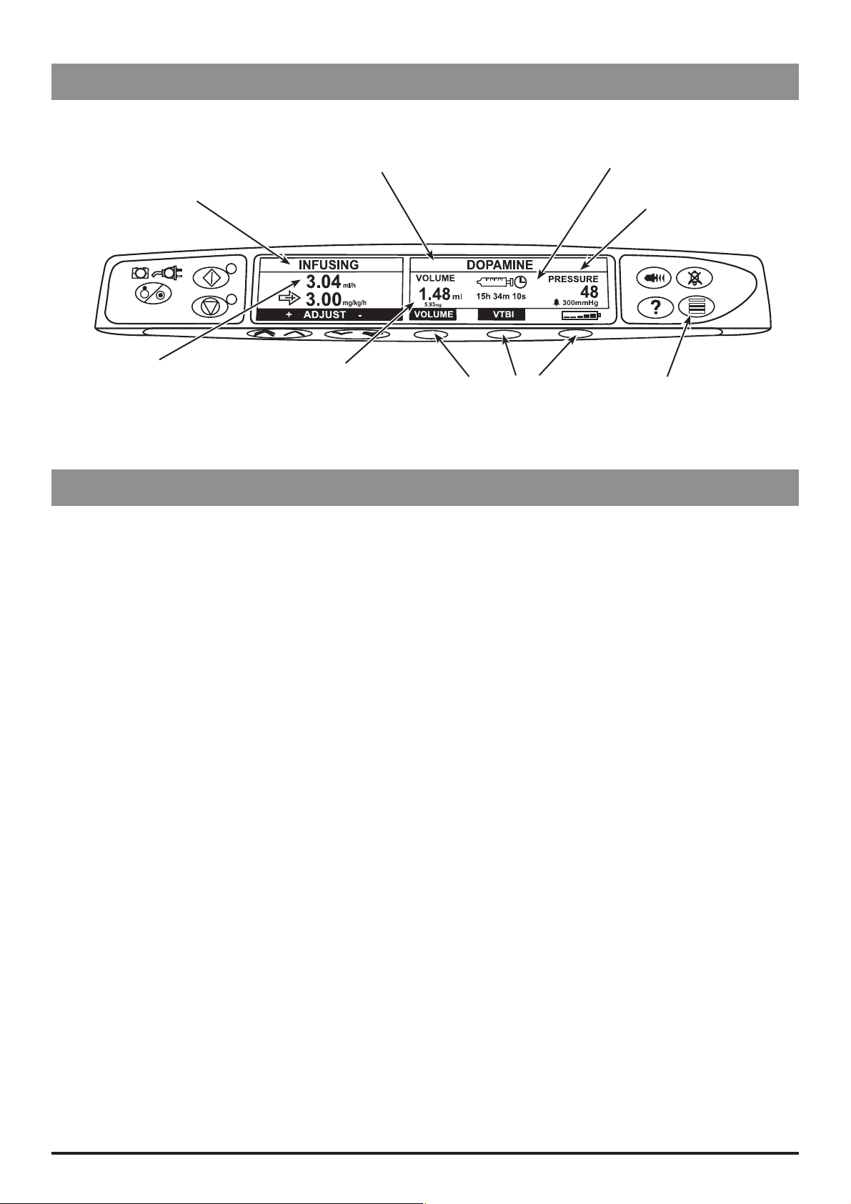
Front panel and main display
The display shown is for general guidance only. For pump specific front panel and main display information refer to relevant
Directions For Use.
Syringe Type Fitted / Drug Name / Profile*
Infusion Status
Infusion Rate Volume Infused
Blank Softkeys
* “Profile” is only available on an Alaris® Syringe Pump with Guardrails® Safety Software with a Data Set loaded.
** Pressure Information is only displayed on the Alaris® CC Syringe Pump.
Time Remaining Icon
Pressure Information** /
Pressure Icon
(if enabled)
Pressure button (not available on
the Alaris® GS Syringe Pump)
Controls and indicators
ON/OFF button - Press once to switch the pump ON. Press and hold down for 3 seconds to switch
a
the pump OFF.
b
h
c
i
d
e
g
f
RUN button - Press to start the infusion. The Green LED will flash during infusion.
HOLD button - Press to put the infusion on hold. The amber LED will be lit while on hold.
MUTE button - Press to silence alarms.
PURGE/BOLUS button - Press to access PURGE or BOLUS soft keys. Press and hold down soft key
to operate.
PURGE the extension set during set up.
Pump is on hold
Extension set is not connected to the patient
Volume Infused (VI) is not added
BOLUS fl uid or drug
Pump is infusing
Extension set is connected to the patient
VI is added
OPTION button - Press to access optional features.
PRESSURE button - Press to display the pumping pressure and alarm level.
BLANK SOFTKEYS - Use in conjunction with the prompts shown on the display.
CHEVRON keys - Double or single for faster/slower, increase or decrease of values shown on main
display.
delivered at an accelerated rate.
BATTERY indicator - When illuminated, indicates that the pump is running on the internal battery.
j
k
Alaris® Syringe Pumps 6/89 1000SM00001 Issue 10
When flashing, indicates that the battery power is low, with less than 30 minutes of use remaining.
AC POWER indicator - When illuminated, indicates that the pump is connected to an AC power
supply and the battery is being charged.
General Information
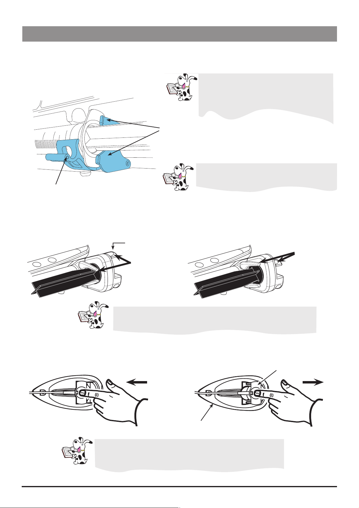
Loading a syringe
1. Squeeze the finger grips together on the plunger holder and slide the mechanism to the right. Pull the syringe clamp
forward and down.
2. Place the syringe barrel flange in the slot between the two blue sections of the syringe flange clamp.
Note: Earlier pumps have a single section syringe
flange clamp. In this instance place the syringe
barrel flange in the space between the syringe
clamp and the syringe flange clamp.
Syringe flange clamp
To ensure the syringe is loaded correctly, check the
syringe remains in position before the syringe clamp
Syringe clamp
is closed.
3. Lift the syringe clamp until it locks against the syringe barrel.
4. Squeeze the finger grips on the plunger holder and slide the mechanism to the left until it reaches the plunger end.
5. Release the finger grips. Ensure that the plunger grippers are securing the plunger in place and the upper finger grip
returns to its original position.
Upper finger grip
Ensure that both plunger grippers are fully locked onto the plunger flange and
the upper finger grip has returned to its original position.
Guide to handling the pressure disc
Pressure Disc
Inserting the
Pressure Disc
When withdrawing the pressure disc, make sure you pull it (with
your finger inside the disc recess) towards the front of the pump as
shown in the diagram above.
Alaris® Syringe Pumps 7/89 1000SM00001 Issue 10
Pressure Transducer
Withdrawing the
Pressure Disc

General Information
Starting the pump
1. Push pump on to bar, the Alaris® Docking Station or mount to pole. Connect to AC Mains.
2. Press the a button to switch pump ON.
3. Follow SETUP / Drug / Profile instructions as per Directions For Use.
4. Load syringe.
5. Insert pressure disc into pressure transducer (Model CC only, required for dedicated mode).
6. Confirm syringe.
7. Change the rate if necessary using the f keys.
8. Purge: Press the i button followed by the PURGE softkey.
9. Connect the pump to test equipment as required (see chapter 2 Configuration & Calibration).
10. Press the b button to start the infusion.
Basic features
Pressure Level Press the e button. Pressure Alarm level and current pressure level are shown on graph.
(not available on Model GS) Use the f keys to adjust pressure alarm level.
Volume to be Infused Press VTBI. Enter VTBI using the f keys. Press OK. Select rate at end of VTBI using
(not available on the f keys. Press OK.
Models TIVA & GS)
Clear Volume Infused Press VOLUME. Select YES (to clear) or NO (to exit).
Purge/Bolus Press the i button, use the f keys to set rate, then press and hold down the
PURGE or BOLUS softkey.
Hands-free Bolus* Press the i button, if required, select HANDSFREE BOLUS, use the f keys to
(Model TIVA only) adjust bolus dose. Use rate softkey to adjust bolus rate if required. Press BOLUS softkey to
deliver.
During PURGE/BOLUS, the pressure limit alarms are temporarily
increased to maximum levels.
Option Button d
Drug Library* Select Drugs and Dosing (Models CC & TIVA) or Drug name (Model GH).
Set VTBI Over Time Specify a VTBI and delivery time (not available on Models TIVA & GS). Pump must be on
hold.
24 Hour Log Volume infused log over 24 hours and accumulative total (on the hour only).
Rate Lock Disables changing rate once infusion has started (not available on Model TIVA).
When rate lock is enabled, the following are unavailable:
1. Rate changes/titration
2. Bolus/Purge
3. Switch pump off
Event Log* Access Event Log. The Event Log holds up to 1500 individual events. Pumps with
Guardrails® Software enabled retain one year of events.
Hospital Name* Displays the name of Hospital/Ward/Department as set up on the pump. Accessible while
the pump is infusing.
Additional options may be shown, please refer to the relevant Directions For Use, for more information.
* Note: For Guardrails® Software enabled pumps or the Alaris® PK Syringe Pump these options may vary or will not be
available. Please refer to the relevant Alaris® Syringe Pump Directions For Use or Guardrails® Editor Directions For Use for
comprehensive information.
Alaris® Syringe Pumps 8/89 1000SM00001 Issue 10

Chapter 2
Configuration & Calibration
In this chapter
Access codes 10
Dedication options (301/302) 10
Data Set Activation (612) 10
Handsfree Bolus (175) 10
Power Lock (711) 10
Configuration options (251) 11
Calibration procedures (243) 15

Configuration & Calibration
Configuration & Calibration
Access codes
The syringe pump software contains a number of configuration and test routines that can be accessed by the user. The
majority of tests are ‘MENU’ driven from a technical access code (see below).
Code Description
123 Self Test Procedure
166 External Reprogramming
167 Teach Learn Procedure
175 Handsfree Bolus
243 Calibration Selection Menu
251 User Configuration Menu
301 Fully Dedicated
302 Semi-dedicated
376 Service Access Menu
401 Upload Data Set to Pump (Guardrails® Software enabled Pumps and the Alaris® PK Syringe Pump)
402 Download CQI Event Log from Pump (Guardrails® Software enabled Pumps only)
418 Alternative Alarm Tone. (Not available for Guardrails® Software enabled Pumps & the Alaris® PK Syringe Pump)
499 Download Data Set from Pump (Guardrails® Software enabled Pumps and the Alaris® PK Syringe Pump)
611 Cold Start (RAM Clear)
612 Data Set activitation (Alaris® PK Syringe Pump)
711 Power Lock (Alaris® PK Syringe Pump)
Each MENU (and some unique items) has its own three-digit access code that can be entered using the following
procedure:
1. Hold down b and turn the pump ON.
2. Enter the required access code using the f keys and the NEXT softkey.
3. When the required code shows on screen, press OK to confirm.
Dedication options (301/302)
Fully Dedicated (set using access code 301) will remind a user that a pressure disc must be fitted to start any infusion. In
this mode occlusion pressures are always displayed in mmHg.
Semi-Dedicated (set using access code 302) will remind a user that a pressure disc must be fitted when drugs and dosing
features are used. When a pressure disc is not in use, pressure levels L-0 to L-10 will be displayed.
Data Set Activation (612)
This code is used to load the predefined pump configuration and drug setup into the non-volatile storage. It is necessary
to enter the code 612 after a cold start (code 611); the configuration and drug setup will then be available in normal
operation.
Alternatively a data set may be uploaded as appropriate. See directions for use contained within the Alaris® PK Editor
Software package.
Handsfree Bolus (175)
Enable or disable the Handsfree Bolus. If enabled pressing bolus button displays screen prompting for hands free or
hands on. Default volume after clear setup is 0.0. Upper amount restricted to bolus volume limit in general options or
drug protocol bolus volume limit.
Power Lock (711)
Available on the Alaris® PK Syringe Pumps with software V2.3.11 & above.
Disabled The new alternative Power Down sequence now allows the user to Power Down the pump whilst the
infusion is suspended (on hold) in TCI mode and predictive TIVA mode.
Enabled The Power Down sequence (Power Lock) remains the same where the user may only Power Down the
pump by stopping the infusion, selecting ‘new operation’ from the options menu, confirming the selection,
then Powering Down the pump.
Alaris® Syringe Pumps 10/89 1000SM00001 Issue 10

Configuration & Calibration
Configuration options (251)
Enter access code 251 to display the User Configuration menu:
Drug Library* Set drug names list on a Model GH - Select Character Group f Select Character f
To go to next Character use NEXT.
Set drug names and protocols for Models CC and TIVA (see drug protocol setup instructions on
following pages).
General Options* See table on the following page.
Clock Set Set the current date and time. To set the clock, use f and NEXT to adjust and OK to store.
Hospital Name* Enables establishment name (max 20 characters) to be displayed during the power-up sequence.
To set the hospital name, use f and NEXT to adjust and OK to store.
Enable Syringes* Configure the type and size of syringes permitted for use.
To enable syringes, use f and SELECT, to enable/disable and OK to store.
Language Configure the language used for messages shown on display.
Select language required using f and SELECT to store.
Contrast Set the display panel contrast. Use f to adjust contrast and OK to store.
Enable Units* Select the type of units permitted for use on the pump. To enable units, use f and
MODIFY, to enable/disable and OK to store.
* Note: For Guardrails® Software enabled pumps and the Alaris® PK Syringe Pump these options may vary or will not be
available. Please refer to the relevant Alaris® Syringe Pump Directions For Use or Guardrails® Editor Directions For Use for
comprehensive information.
Alaris® Syringe Pumps 11/89 1000SM00001 Issue 10
Configuration & Calibration
Configuration & Calibration
Configuration options (251) (continued)
Alaris® TIVA Syringe Pump drug protocol setup
Select Drug Library from Configuration Options (251).
Use f to select drug and press MODIFY to modify selected drug or NEW to create new drug name.
QUIT will return to 251 main menu.
When modifying a drug protocol, pressing BACK at any time will take you to the previous step.
Modify - Existing drug
ENABLE/DISABLE - Enables or disables the drug being available.
DELETE - Select Yes to delete from drug library.
EDIT - See table below.
Edit Drug Protocol - New or existing drug
Press OK softkey to confirm each step.
Drug Option
Drug Name
Concentration Units
Minimum Concentration
Default Concentration
Maximum Concentration
Dose Rate Units
Induction Dose
Induction Time
Pause After Induction MODIFY
Maintenance Rate
Bolus Dose
To Adjust
(Softkeys are shown in Bold)
Select Character Group f
Select Character f
To go to next Character NEXT
f
f or OFF
f or OFF
f or OFF
f
f or OFF
f
f
f
Bolus Rate RATE
Hands Free Bolus MODIFY
Alaris® Syringe Pumps 12/89 1000SM00001 Issue 10
Configuration & Calibration
Configuration & Calibration
Configuration options (251) (continued)
Alaris® CC Syringe Pump* drug protocol setup
Select Drug Library from Configuration Options (251).
f to select drug and press MODIFY to modify selected drug or NEW to create new drug name.
Use
QUIT will return to 251 Main menu.
When modifying a drug protocol, pressing BACK at any time will take you to the previous step.
Modify - Existing drug
ENABLE/DISABLE - Enables or disables the drug being available.
DELETE - Select Yes to delete from drug library.
EDIT - See table below.
Edit Drug Protocol - New or existing drug
Press OK softkey to confirm each step.
* Note: For Guardrails® Software enabled pumps this option will not be available. Please refer to the relevant Alaris®
Syringe Pump Directions For Use or Guardrails® Editor Directions For Use for comprehensive information.
Drug Option
Drug Name
Dose Rate Units
Maximum Dose
Default Dose
Minimum Dose
Concentration Units
Minimum Concentration
Default Concentration
Maximum Concentration
Maximum Bolus
Bolus Rate
To Adjust
(Softkeys are shown in Bold)
Select Character Group f
Select Character f
To go to next Character NEXT
f
f or OFF
f or OFF
f or OFF
f
f or OFF
f or OFF
f or OFF
f or OFF
f
Pressure Alarm
Alaris® Syringe Pumps 13/89 1000SM00001 Issue 10
f or OFF

Configuration & Calibration
Configuration & Calibration
Configuration options (251) (continued)
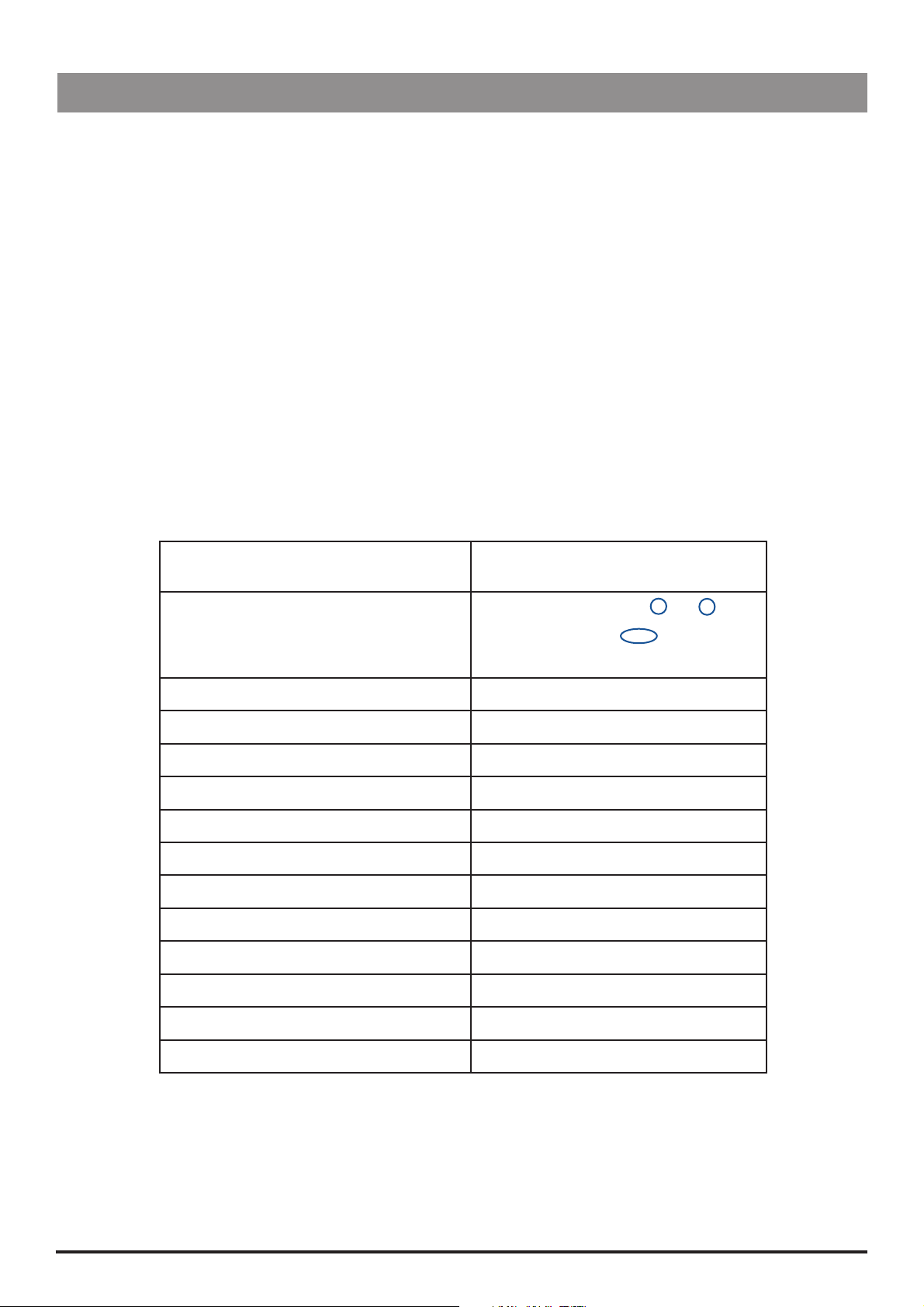
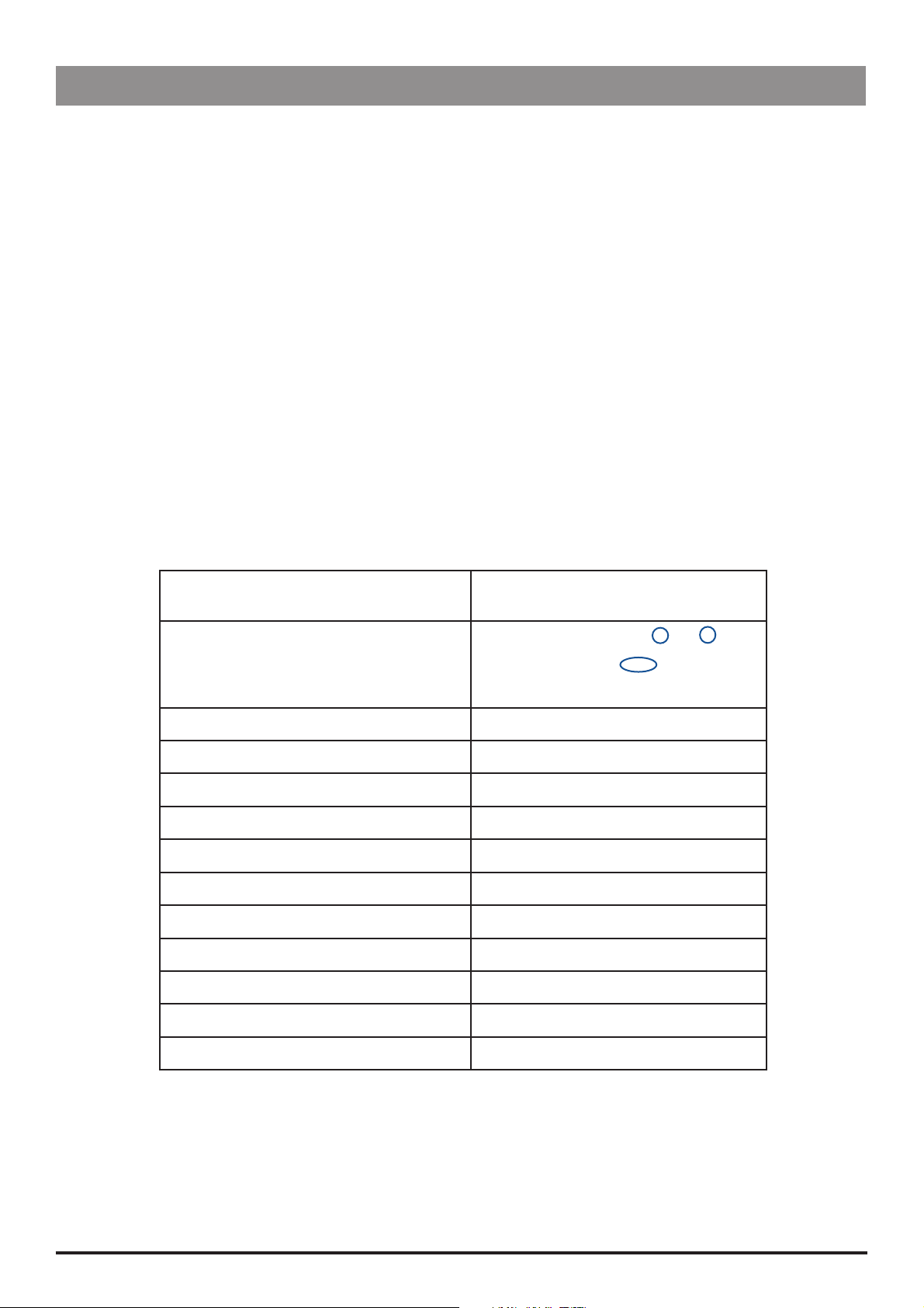
General options
Option Description
NURSE CALL FITTED Enables Nurse Call (hardware option).
NURSE CALL INVERT When enabled, the nurse call output is inverted.
RS232 SELECTED Sets the pump’s communications to use RS232 (hardware option).
NEOI WARNING Sets the Near End Of Infusion (NEOI) warning time.
EOI POINT Sets the End Of Infusion volume.
KVO AT EOI Enables pump to run at the Keep Vein Open (KVO) rate when End Of
Infusion (EOI) is reached.
KVO RATE Sets the Keep Vein Open (KVO) rate.
BACK OFF Motor will reverse to relieve line pressure when an occlusion occurs.
AUTO SAVE When disabled, the patient information is cleared on power up.
RATE LOCK When enabled, the rate can be locked to prevent unwanted changes
of the set infusion rate.
QUIET MODE When enabled, the button beeps are muted.
AC FAIL When enabled, the AC Power Failure Alarm will sound if AC power is
disconnected.
RATE TITRATION When enabled, the rate can be changed whilst the pump is infusing.
PRESSURE DISPLAY Enables / disables the Pressure Icon on the main display.
AUTO PRESSURE Enables / disables the automatic pressure alarm level option.
AUTO SET PRESSURE Automatically sets the line occlusion pressure alarm level to a
specified amount above the current pressure.
AUTO OFFSET Adjusts the automatic offset value used by auto pressure and auto
set pressure.
HANDS FREE BOLUS Enables / disables hands-free bolus.
CAP PRESSURE Sets the maximum pressure limit.
PRESSURE DEFAULT Sets the default occlusion alarm level.
DEFAULT BOLUS VOLUME Sets the default hands-free bolus volume for No Drug mode only.
MAX PRESSURE Sets the maximum pressure limit.
WEIGHT Sets the default patient weight in kg.
CAP RATE Sets the maximum value for infusion rate.
PURGE RATE Sets the purge rate.
PURGE VOLUME LIMIT Sets the maximum permissible purge volume.
PURGE SYRINGE Prompt to purge syringe after confirmation.
BOLUS Enables / disables the bolus feature.
DEFAULT BOLUS Sets the default bolus rate.
CAP BOLUS RATE Sets the maximum value for bolus rate.
BOLUS VOL LIMIT Sets the maximum permissible bolus volume.
MANUAL BOLUS Volume infused will be increased if plunger is manually moved in and
syringe remains confirmed.
CALL BACK TIME Adjusts the time for the pump to sound the call back alarm.
VTBI CLEAR RATE Rate will be set to zero when VTBI has been set-up with stop as the
end rate.
EVENT LOG DISPLAY Enables / disables the event log display.
BATTERY ICON Enables / Disable the Battery Icon on the main display.**
AUDIO VOLUME Sets the alarm volume of the pump at high, medium or low.
AUTO NIGHT MODE Sets Backlight to dim between 21:00 and 06:00hrs.
Models
GS GH* CC* TIVA
Key:
= available option
= unavailable option
Alaris® Syringe Pumps 14/89 1000SM00001 Issue 10
* For Guardrails® Software enabled pumps and the Alaris® PK Syringe Pump these options may vary or will not be available, with only
the first three options listed in table above adjustable in the General Options on the pump. Please refer to the relevant Alaris® Syringe
Pump Directions For Use or Guardrails® Editor Directions For Use for comprehensive information.
** For Alaris® GS Syringe Pump the battery icon can be seen via the Options menu by pressing the d key.
Configuration & Calibration
Configuration & Calibration
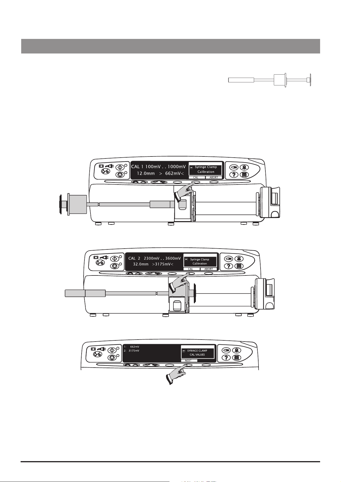
Calibration procedures (243)
Enter access code 243 to display the Calibration Selection menu (see Access
Codes).
SYRINGE CLAMP calibration
Fit calibration tool into position on pump as shown in Steps 1-2 and close the
clamp. At each step, CAL is displayed if value is within tolerances.
Press CAL button to store calibration point.
Note: If CAL is not displayed, check for correct positioning of calibration tool.
If calibration cannot be performed, repairs to pump may be necessary.
Note: The calibration values shown on the displays are for illustrative use only and may vary.
Step 1
Calibration tool required: 1000TG00095
Step 2
Step 3
Alaris® Syringe Pumps 15/89 1000SM00001 Issue 10

Configuration & Calibration
Configuration & Calibration
Calibration procedures (243) (continued)
PLUNGER POS (position) calibration
Fit calibration tool in position on pump as shown in Steps 1-3. At each step CAL is displayed if value is within tolerance.
Press CAL button to store calibration point.
Note: If CAL is not displayed, check for correct positioning of calibration tool. If
calibration cannot be performed, repairs to pump may be necessary.
Note: The calibration values shown on the displays are for illustrative use only and
may vary.
Step 1
Channel for locking clip
Calibration tool required: 1000TG00095
Step 2
Close-up of calibration tool, showing
locking clip in position.
Step 3
Step 4
Locking clip
Alaris® Syringe Pumps 16/89 1000SM00001 Issue 10

Configuration & Calibration
Calibration procedures (243) (continued)
SYRINGE FORCE calibration
Precondition:
This preconditions the mechanism and should only be done if motorplate
or chassis has been replaced. Fit Calibration tool as shown, zero the gauge,
run until gauge registers 10kgf and then carefully declutch mechanism and
withdraw plunger. Do not press any button during this procedure.
To convert Kilograms of Force (kgf) to Newtons (N) multiply by 9.806650. For
example 10kgf = 98.07N.
Excessive force will damage the plunger mechanism. Do not apply more than 10
kgf ±0.05kgf to the plunger mechanism at any time.
Calibration tool required:
0000TG00200 (top) or
0000TG00020 (bottom)
Note: The calibration values shown on the displays are for illustrative use only and may vary.
Precondition
10kgf ±0.05kgf
Zero Gauge Syringe Force Calibration Tool Plunger
Fit Calibration tool and position plunger as shown in Steps 1 to 3, zero the gauge. At each step press CAL when required
calibration force is reached.
Note: If CAL does not appear in display, check for correct positioning of tool. If calibration cannot be performed, repairs
to pump may be necessary.
Allow 30 seconds for pressure to stabilise following any preconditioning calibration.
Step 1
0kgf ±0.05kgf
Alaris® Syringe Pumps 17/89 1000SM00001 Issue 10

Configuration & Calibration
Configuration & Calibration
Calibration procedures (243) (continued)
SYRINGE FORCE calibration (continued)
Step 2
3Kgf ±0.05Kgf
Step 3
10Kgf ±0.05Kgf
Step 4
Use of the 0000TG00200 Digital Occlusion Testgear.
The 0000TG00200 Occlusion testgear uses a digital force gauge to register applied forces.
Please refer to the MecMesin Compact Gauge Operation Instructions supplied for detailed
operational information and power options and requirements.
To prepare the testgear for use, load into the syringe pump.
• Ensure there is nothing touching the testgear plunger (such as the syringe plunger drive).
• Turn on the Compact Gauge using the ‘On/Zero’ key.
• Select ‘kg’ force units, and ‘MAX’ reading option.
• If the display indicates other than 0.00kg, zero the system using the ‘On/Zero’ key.
Operate the system as required for performing the calibration activity.
Before the next use, ensure the ‘MAX’ reading is cleared using the ‘On/Zero’ key.
Alaris® Syringe Pumps 18/89 1000SM00001 Issue 10

Configuration & Calibration
Configuration & Calibration
Calibration procedures (243) (continued)
LINE PRESSURE calibration – Alaris® CC Syringe Pump ONLY
Tools required:
Pressure gauge (range 0-1400 mmHg)
(Tolerance +/- 0.1mmHg)
Dedicated pressure sensing disc extension set
(i.e. G30402M)
50ml Luer-lock syringe
Dedicated pressure sensing disc extension set
Pressure Transducer
Pressure gauge50ml Luer-lock syringe
Load pressure disc infusion set into transducer. Connect infusion set to syringe and gauge. Using syringe, apply pressure
required as shown at steps 1-3. At each step press CAL when required calibration pressure is displayed on pressure
gauge.
Note: The calibration values shown on the displays are for illustrative use only and may vary.
Step 1 25mmHg ± 1mmHg
Step 2 500mmHg ± 1mmHg
Step 3 1000mmHg ± 1mmHg
Step 4
Alaris® Syringe Pumps 19/89 1000SM00001 Issue 10

Configuration & Calibration
Configuration & Calibration
Calibration procedures (243) (continued)
BATTERY calibration
1. Connect the Pump to AC mains.
2. Select BATTERY CALIBRATION from menu and press OK.
3. The pump will automatically run the battery calibration. Battery calibration cycles the battery through a charge,
discharge and re-charge sequence during which the gas gauge within the battery pack will be updated with a
measurement of the current capacity of the cells.
Battery compartment should be ventilated during calibration (open battery cover).
Pump may fail calibration if too hot, so care should be taken not to calibrate too
many pumps in close proximity (in a docking station, for example).
Ensure that the battery is supported as you open the battery compartment.
Disconnecting the AC mains at any time during calibration will cause battery
calibration to fail.
4. When calibration is complete, the following is shown on the display:
1
4
2
CAP 2488 mAh 00:09
CHR 2362 mAh 05:28
VOL 8.21 V 02:05
3
Value Description Pass Criteria
Battery Capacity Pack capacity value updated after measured discharge phase (if
1
Current Battery Charge
2
Level
Battery Voltage Current pack voltage. n/a
3
Initial Charge Time Time taken during intial charge phase. Intial charge phase checks
4
Discharge Time Time taken during measured discharge phase. Pack is discharged
5
Final Charge Time Time taken during final charge phase. Pack is fully recharged
6
changed).
Current charge in pack. n/a
pack is fully charged and if not it is charged.
to determine how much charge is available from the pack.
ready for use.
6
5
BATTERY STATE
OK
FINISH
Greater than 2100mAh
Lower than 2 hours 59
minutes
Between 4 hours 15 minutes
& 10 hours
Lower than 2 hours 59
minutes
5. All pass criteria (see table above) should be met and the pump should display FINISH at the end of the calibration
otherwise calibration has failed. If calibration has failed retry calibration or replace battery.
6. Press OK to exit.
The plunger drive will move automatically during the discharge phase, so ensure
that the plunger drive is not obstructed during calibration (remove syringes etc).
Alaris® Syringe Pumps 20/89 1000SM00001 Issue 10

Routine Maintenance
In this chapter
Self-test procedure (123) 22
Chapter 3
Comms test (123) 23
Data transfer 24
Information logs (376) 27
Recommended cleaning and inspection 28
Performance verification procedure 29

Routine Maintenance
Routine Maintenance
For routine maintenance, the following self-test and performance verification procedures should be performed.
Refer to the relevant Directions for Use for the recommended routine maintenance period.
Self-test procedure (123)
Self-tests included in full test
Enter access code 123 to view the Test Selection menu (see Access Codes in chapter 2). Refer to table below for the tests
in each menu item.
Test Section Test Action
Software info Displays the software version.
Software
Data Set Info
Safety ID Check displays the version of the safety ID.
Displays the Data Set information. (pumps with Guardrails® Safety
Software only)
Safety Processor
Full only
Sensor
Safety LED Check red LED illuminated.
Safety Alarm Check Backup alarm sounds.
Serial Number Check displays serial number of unit.
Language Check displays correct language.
Real-time Clock Check displays correct date and time.
Service Date Check displays date when service is next required.
Disc Detect
Line Pressure
Motor Encoder Check motor runs and Passed is displayed.
Drive Engage
Plunger Fit Check display indicates if the Plunger button is Out or In.
Plunger Position
Syringe Clamp
Check the display changes correctly to indicate if a disc is Out or In
(Model CC only).
Check pressure is 000mmHg +/-20mmHg with no pressure applied
(Model CC only).
Check display indicates Drive Engaged or Disengaged when clutched/
declutched.
Check display smoothly and continuously changes during full plunger
travel.
Insert the syringe size calibration tool (1000TG00095) and check the
following values are displayed for diameters inserted:
12mm diameter = 11.5 to 12.5mm
32mm diameter = 31.5 to 32.5mm
Syringe Force Check motor runs and syringe force is displayed.
Battery Battery Check displays values in CAP, CHR and VOL; no dashes should be seen.
Audio Audio Speaker Check the main audible alarm sounds.
Display Check that all of the display pixels are illuminated.
Backlight Check that the backlight switches from LOW to HIGH when indicated.
Battery LED Check the Battery LED (Amber) flashes.
Visual Indicator
Key Keypad Press the key indicated and check changes to next key.
Comms Comms RS232 only. Check Nurse call and RS232 operation.
Alaris® Syringe Pumps 22/89 1000SM00001 Issue 10
Start LED Check the Start LED (Green) flashes.
Stop LED Check the Stop LED (Amber) flashes.
Warning LED Check the Warning LED (Amber) flashes.
Alarm LED Check the Alarm LED (Red) flashes.

Routine Maintenance
Routine Maintenance
Self-test procedure (123) (continued)
Self-tests not included in full test
Test Section Test Action
Remote Remote Check the function of the IrDA output for remote access
Syringe clamp Displays calibration values for Closed and Open positions.
Calibration records
Linearity
Plunger position Displays calibration values for Left, Middle and Right positions.
Syringe force Displays calibration values for 0, 3 and 10 kgf.
Line pressure Displays calibration values for 25, 500 and 1000mmHg (Model CC only)
Linearity Check the mechanism runs full travel and graph displays smooth linear travel.
Occlusion base Check the occlusion base level is within tolerance shown on graph.
Comms test (123)
Select COMMS TEST from the displayed menu. Note: Section only applicable if RS232 Hardware option is fitted.
No specific customer test equipment is available to conduct the RS232 on nurse call alarm tests. It is assumed that the
customer will have associated systems that make use of the RS232 and nurse call options, hence:
The nurse call system can be tested, once connected to the customer facility, by running the pump and simulating an
alarm condition (e.g. Disengaging the drive while running).
The RS232 system can be tested by communicating with the pump using a customer application.
If no customer systems are available for in-use testing, the following connections to the 9 pin D type output socket will
permit testing. It is recommended that all test connections are made via a 9 way D type plug that can be fitted into the
pump socket.
Test Description
RS232 Test Only available when Nurse Call option is fitted. Note: NURSE CALL FITTED & RS232 SELECTED
must be enabled () in access code 251 General Options for this test to work. Connect the 9-pin
D type connector to the 9 pin D type output socket at the rear of the pump. The display ‘_ _ _ _’
will change to PASS if the communications test is successful.
Nurse Call Only available when Nurse Call option is fitted. Note: NURSE CALL FITTED & RS232 SELECTED
must be enabled () in access code 251 General Options for this test to work. Locate the 9-pin
D type connector at the rear of the pump. Check that the Nurse Call relay switches from NC to
NO connections during test.
GND DSR RXD TXD NC C
4
5
32
RS232 pinout
1
9876
CTS
NC O
NC
COM
Pin Number
(Pump Socket Id)
1 Nurse call relay - normally closed
2 Link pin 2 to pin 3 RS232 Tx and RX test link. With RS232 test in progress -
3 See pin 2 -----
4 Not used -----
5 0 volt line With respect to pin 7.
6 Not used -----
7 Apply 9 to12 volts DC RS232 Power supply - with respect to pin 9.
8 Nurse call relay - normally open connection With nurse call test in progress - Check continuity to pin 5
9 Nurse call relay - common connection ----
Alaris® Syringe Pumps 23/89 1000SM00001 Issue 10
Required Action Comments
With nurse call test in progress - Confirm continuity with
connection
pin 5 - Alternately switches with pin 8.
Confirm 'PASS' is displayed on test screen.
- Alternately switches with pin 1.

Routine Maintenance
Routine Maintenance
Data transfer
Upgrading software
Upgrade of the Alaris® Syringe Pump (except the Alaris® TIVA Syringe Pump) software to V1.5.10 or
greater is recommended at the next service, for Alaris® Syringe Pumps with software versions V1.5.9
and below. Perform upgrades by acquiring the software upgrade kits specified in spare parts listings.
This will address a potential issue that may result in a condition where the running LED is flashing, the
infusion status shows "INFUSING" but the volume infused display will not increment and no drug will
be infused into the patient.
This potential issue may occur under the following remote circumstances : (i) A new syringe was recently fitted into the drive mechanism and
(ii) An infusion is started, very quickly stopped and then restarted. (The pump must be
stopped between 0.375 secs and 0.435 secs after starting - a window of 0.06 secs.)
If the pump is subsequently stopped and restarted, the infusion will start normally.
When upgrading a pump from one software version to another where the first or middle digit changes,
cold start will be required before and after software upgrade. Calibration will also be required after
software upgrade and cold start.
Tools required
The Software Distribution Disk (See table below) IrDA port on PC or Comms Port
Programming kit 1000SP00172 RS232 cable 1000SP00336
(Includes Programme Header and IrDA cable) Ver. 3 Software Maintenance Utility (SMU) 1000CD00028
IrDA power-down test
To check PC is set up correctly for communication with Alaris® Syringe Pumps the Power Down Test needs to be
performed on one Alaris® Syringe Pump only as follows:
1. Load the IrDA Power Down Test program on your PC.
2. Select GO on the PC software program.
3. Align the IrDA converter with the pump IrDA window (optimum distance is 5cm).
4. Connect to serial port.
5. Enter access code 166.
6. Press Yes to continue Bootstrap.
7. Select IrDA interface.
8. Select a Baud rate of 115200.
9. The pump will then display Bootstrap in progress.
10. Press the c button to silence the alarm.
11. Select Transmit on PC. Check progress bar moves on PC and pump powers down.
Software Versions available
Syringe Pump
Model
Alaris® GS Syringe
Pump
Mk1/Mk2 Mk3 Mk1/Mk2 Mk3 Mk3
1000SP01221
(MP v1.5.10)
Software Enhanced Software Guardrails® Safety Software
1000SP01225
(MP v2.0.0)
1000SP01270
(MP v1.9.4)
1000SP01276
(MP v2.3.6)
Alaris® GH Syringe
Pump
Alaris® CC Syringe
Pump
Alaris® TIVA Syringe
Pump
Alaris® PK Syringe
Pump
1000SP01221
(MP v1.5.10)
1000SP01221
(MP v1.5.10)
1000SP01221
(MP v1.6.2)
1000SP01226
(MP v2.0.0)
1000SP01227
(MP v2.0.0)
1000SP01228
(MP v2.1.0)
1000SP01270
(MP v1.9.4)
1000SP01270
(MP v1.9.4)
1000SP01270
(MP v1.9.4)
1000SP01268
(MP v2.3.6)
1000SP01267
(MP v2.3.6)
1000SP01269
(MP v2.3.6)
1000SP01289
(MP v3.2.12)
MP v3.1.4
(Installed by Cardinal Health Personnel)
MP v3.1.4
(Installed by Cardinal Health Personnel)
Key: MP = Main Processor. Mk1/Mk2/Mk3 are the released versions of the Control PCB.
Alaris® Syringe Pumps 24/89 1000SM00001 Issue 10

Routine Maintenance
Routine Maintenance
Data transfer (continued)
Soft bootstrap
1. Load the software program onto your PC. Start the ‘MP Only’ version of relevant pump software. Check the correct
pump type is displayed.
2. Select GO.
3. Align the IrDA converter pump with the IrDA window (optimum distance is 5cm), or connect RS232 cable.
4. Connect to serial port.
5. Enter access code 166.
6. Press Yes to continue Bootstrap.
7. Select IrDA interface or RS232 interface.
8. Select a Baud rate of 115200.
9. The pump will then display Bootstrap in progress.
10. Press the c button to silence the alarm.
11. Select Start on PC. Monitor progress of all selected channels
12. Power down pump.
Hard bootstrap
1. Load the software program onto your PC. Start the relevant pump software (not the ‘MP Only’ version).
2. Disconnect the battery and separate the pump.
3 Fit the Programme header onto the control board.
4. Reconnect the battery. The pump will alarm, press the c button to silence.
5. Align the IrDA converter pump with the IrDA window (optimum distance is 5cm), or connect RS232 cable.
6. Connect to serial port.
7. Switch the Programme header to the correct position either RS232 or IrDA.
8. Switch on the Programme header.
9. Select GO on the PC software program.
10. Select Start on PC. Monitor progress of all selected channels
11. Power down pump.
Cold start
It may be necessary to carry out a cold start if the pump has changed between certain software. Refer to documentation
supplied with the software disk to see if cold start is required.
1. Enter access code 611, then power down when prompted.
2. Perform a full calibration.
Caution - Potential Erasure of Data:
Cold Start erases ALL information from the pump. This feature should only be
used when changing between incompatible software versions. Full recalibration
and reconfiguration will be required. Cardinal Health technicians should not reinstate drug information (this MUST be left to the customer).
Power Failure
Failures may occur when using laptops when communicating with Alaris® Syringe
Pumps, due to power requirements.
External power supply may be used in conjunction with IrDA or RS232 cable to
compensate for lack of power from laptop.
Please Note IrDA data transfer can be affected by bright sunlight or fluorescent
lighting.
Alaris® Syringe Pumps 25/89 1000SM00001 Issue 10

Routine Maintenance
Routine Maintenance
Data transfer (continued)
Teach Learn (Software versions V1.4.13 and above)
1. For the teacher pump only (not required for learn pumps), in General Options 251, switch off RS232 before
commencing Teach Learn procedure.
2. Turn the teacher pump on in normal operation.
For multiple teach-learn operations, to avoid call-back alarm every 2 minutes, turn teacher
pump on in access code mode.
3. Enter the access code 167 on learn pump.
4. Align the two IrDA ports on the pumps (optimum distance is 5cm).
5. Press OK and then Yes to confirm.
6. A progress bar will travel across the learn pump.
7. When completed, select No to cancel retry.
Possible reasons for failure:
RS232 is not switched off.
If software versions are different, confirm teach learn procedure on learner pump to continue. Verify settings after
completion of learn.
The pump models are different. For example, an Alaris® GS Syringe Pump can only teach an Alaris® GS Syringe Pump.
The line of sight between the IrDA windows was obstructed during data transfer.
Check protocols are correct on learn pump after teach learn procedure, before returning
pump to use.
After a Teach/learn procedure it is necessary to clear the previous patient setup in order to
update the syringe information. On power-up after Teach/learn and when prompted with
CLEAR SETUP, select YES.
Event Log download
A PC application known as the Event Log Download Utility (ELDU) (part number 1000SP00209) is available to download
logs from Alaris® Syringe Pumps.
ELDU operation
1. Click on ELDU icon on PC.
2. Click Accept to agree with Restrictions of Use and continue.
3. Select Configure from drop-down menu.
4. Select Setup Pump and choose Alaris® as pump type.
5. Select Settings to select log to be downloaded.
6. Check communications are set as follows:
- Required PC com port selected.
- Set baud rate to 38400.
7. Click OK to confirm.
8. Align the IrDA converter pump with the IrDA window (optimum distance is 5cm), or connect RS232 cable.
9. Power up pump.
10. Click Download Log from main screen.
11. Press Close, when finished.
12. Select File from drop-down menu and save file. Log may be printed here as required.
Alaris® Syringe Pumps 26/89 1000SM00001 Issue 10

Routine Maintenance
Routine Maintenance
Data transfer (continued)
Data Set Upload and Download (401 & 499)
Upload Data Set to an Alaris® Syringe Pump with Guardrails® Safety Software or an Alaris® PK Syringe Pump (401)
Using the Guardrails® Editor Transfer Tool or Alaris® PK Editor Software Transfer Tool allows a released Data Set to be
uploaded to an Alaris® Syringe Pump.
Download Data Set from an Alaris® Syringe Pump with Guardrails® Safety Software or an Alaris® PK Syringe Pump
(499)
Using the Verification Tool allows an uploaded Data Set in an Alaris® Syringe Pump to be downloaded to a PC for
comparison and verification.
Download CQI Event Log (402)
Download CQI Event Log from an Alaris® Syringe Pump with Guardrails® Safety Software (402)
Using the CQI Event Log Downloader allows the CQI Event Log to be downloaded from an Alaris® Syringe Pump to a PC
for use with the Guardrails® CQI Reporter. The Guardrails® CQI Reporter is a program for querying and reporting on the
collective event data allowing the user to analyse trends in medication administration and track medication errors.
Warning At no time should the Guardrails® Safety Software or the Alaris® PK Editor
Software be used to upload to or download from an Alaris® Syringe Pump
while the pump is connected to a patient.
For more information relating to the Guardrails® Editor, the Alaris® PK Editor
Software and the Guardrails® CQI Reporter refer to the relevant Directions For
Use supplied with the software.
Information logs (376)
Use access code 376 to view the information logs (see Access Codes in chapter 2).
Log View Notes
Service Displays the last 10 fault codes.
Clear Service Clears any information stored in the service log.
Displays the complete event log (maximum 1500 events
Event
Key
Use
except Pumps with Guardrails® Software enabled which
have one year of events).
Displays the last 200 key presses and the time they
occurred.
Displays the hours of use since reset and since last cold
start.
Option to view the time and date at
which they occur.
Will not be available if there is no data
in the service log.
Option to view the time and date at
which they occur.
Does not record while in Tech mode.
Press OK to clear hours since reset.
Access code 376 provides the following additional service options:
Service Date Set the date when pump will display ‘Service due’ and any service message entered.
Service Message Enter message to be displayed on service date.
Serial Number Record the serial number of the pump.
Unit Reference Free-form text field for user reference only.
Event Log Access provided when standard power-up mode leads to errors such that the Event Log access
from the Options d button cannot be accessed.
PCB Identification Allows Control PCB ID to be reviewed. (Pumps with Guardrails® Safety Software only)
Number
Alaris® Syringe Pumps 27/89 1000SM00001 Issue 10
 Loading...