

Cardinal Health Alaris Directions For Use Manual
Directions for Use
Alaris® System
(with PC Unit, Model 8000)
Supports Guardrails® Suite MX with Guardrails® Point-Of-Care software and v9 Operating System software.
February 2007
FU
S
N
ONI
T
O
M
R
S
M
T
R
A
N
A
L
A
D
B
Y
FU
S
E
IN
S
T
A
M
N
R
D
A
B
L
A
Y
E
I
S
T
A
M
N
R
D
A
B
L
A
Y
FU
S
E
N
I
S
T
A
N
M
D
R
A
L
A
B
Y
%SpO
PULSE (BPM)
2
CHANNEL
SELECT
MONITOR
CHANNEL
OFF
RATE (mL/h)
CHANNEL
SELECT
PAUSE
CHANNEL
OFF
RESTART
SILENCE
OPTIONS
CLEAR
RATE (mL/h)
CHANNEL
SELECT
PAUSE
CHANNEL
SYSTEM
ON
1
2
4
7
3
6
5
8
0
ENTER
9
CANCEL
.
OFF
RESTART
RATE(mL/h)
CHANNEL
SELECT
PAUSE
CHANNEL
OFF
RESTART
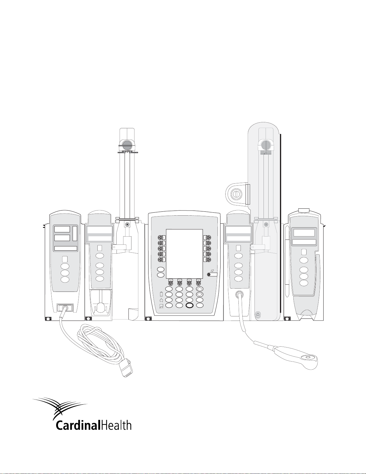
Alaris® Products

Table of Contents
Each of the Alaris® product-specific Sections has its own table of contents.
General Contact Information
. . . . . . . . . . . . . . . . . . . . . . . . . . . . . . . . . . . . . . . . . . . . . . . . . . . . . . . . . . . . . . . . . . . . i
Introduction . . . . . . . . . . . . . . . . . . . . . . . . . . . . . . . . . . . . . . . . . . . . . . . . . . . . . . . . . . . . . . . . . . . . . . . . . . . . . . . . . . . . . . . . . ii
Installation. . . . . . . . . . . . . . . . . . . . . . . . . . . . . . . . . . . . . . . . . . . . . . . . . . . . . . . . . . . . . . . . . . . . . . . . . . . . . . . . . . . . . . . . . . . iv
PC Unit . . . . . . . . . . . . . . . . . . . . . . . . . . . . . . . . . . . . . . . . . . . . . . . . . . . . . . . . . . . . . . . . . . . . . . . . . . . . . . . . . . . . . . . . . . . . . . 1
Pump and Syringe Modules . . . . . . . . . . . . . . . . . . . . . . . . . . . . . . . . . . . . . . . . . . . . . . . . . . . . . . . . . . . . . . . . . . . . . 2
PCA Module . . . . . . . . . . . . . . . . . . . . . . . . . . . . . . . . . . . . . . . . . . . . . . . . . . . . . . . . . . . . . . . . . . . . . . . . . . . . . . . . . . . . . . . . 3
SpO2 Module. . . . . . . . . . . . . . . . . . . . . . . . . . . . . . . . . . . . . . . . . . . . . . . . . . . . . . . . . . . . . . . . . . . . . . . . . . . . . . . . . . . . . . . . 4
EtCO2 Module . . . . . . . . . . . . . . . . . . . . . . . . . . . . . . . . . . . . . . . . . . . . . . . . . . . . . . . . . . . . . . . . . . . . . . . . . . . . . . . . . . . . . . 5
Auto-ID Module . . . . . . . . . . . . . . . . . . . . . . . . . . . . . . . . . . . . . . . . . . . . . . . . . . . . . . . . . . . . . . . . . . . . . . . . . . . . . . . . . . . . 6
Nurse Call Accessory. . . . . . . . . . . . . . . . . . . . . . . . . . . . . . . . . . . . . . . . . . . . . . . . . . . . . . . . . . . . . . . . . . . . . . . . . . . . . 7
Communications Interface Board Accessory. . . . . . . . . . . . . . . . . . . . . . . . . . . . . . . . . . . . . . . . . . . . . . . . . 8
Appendix
Maintenance. . . . . . . . . . . . . . . . . . . . . . . . . . . . . . . . . . . . . . . . . . . . . . . . . . . . . . . . . . . . . . . . . . . . . . . . . . . . . . . . . . . . . . A-1
Cleaning . . . . . . . . . . . . . . . . . . . . . . . . . . . . . . . . . . . . . . . . . . . . . . . . . . . . . . . . . . . . . . . . . . . . . . . . . . . . . . . . . . . . . . . A-1
Service Information
Warranty . . . . . . . . . . . . . . . . . . . . . . . . . . . . . . . . . . . . . . . . . . . . . . . . . . . . . . . . . . . . . . . . . . . . . . . . . . . . . . . . . . . . . . . A-3
Regulations and Standards . . . . . . . . . . . . . . . . . . . . . . . . . . . . . . . . . . . . . . . . . . . . . . . . . . . . . . . . . . . . . . . . . . . . . A-5
Compliance
Trademarks . . . . . . . . . . . . . . . . . . . . . . . . . . . . . . . . . . . . . . . . . . . . . . . . . . . . . . . . . . . . . . . . . . . . . . . . . . . . . . . . . . . . A-14
. . . . . . . . . . . . . . . . . . . . . . . . . . . . . . . . . . . . . . . . . . . . . . . . . . . . . . . . . . . . . . . . . . . . . . . . . . . . . . . . . . . . A-5
. . . . . . . . . . . . . . . . . . . . . . . . . . . . . . . . . . . . . . . . . . . . . . . . . . . . . . . . . . . . . . . . . . . . . . . . . . . . . A-2
Order Numbers:
Electronic Copy: 10015905
Printed Copy: 10110697 ©2006, 2007 Cardinal Health, Inc. or one of its subsidiaries. All rights reserved.
Alaris® System (with v9 Model 8000) DFU

Cardinal Health
®
Alaris
10221 Wateridge Circle
Products
San Diego, California
cardinal.com/alaris
Maintenance and service information support; troubleshooting.
General Contact Information
92121
Customer Advocacy - North America
Clinical and technical feedback.
Phone: 800.854.7128, Ext. 7812
E-Mail: CustomerFeedback@cardinal.com
Technical Support - North America
United States - Phone:
858.458.6003
800.854.7128, Ext. 6003
Within Canada: 800.387.8309
From United States: 800.908.9918
Canada - Phone:
Customer Care - North America
Instrument return, service assistance, and order placement.
United States - Phone: 800.482.4822 Canada - Phone: 800.387.8309
Alaris® System (with v9 Model 8000) DFU
i

Introduction
The Alaris® PC unit Section of this Directions for Use ("DFU")
provides procedures and information applicable to the Alaris
System and the PC Unit. Each of the other major Sections
provides product-specific procedures and information.
®
The Alaris
System is a modular system intended for adult,
pediatric and neonatal care in today’s growing professional
healthcare environment. It consists of the PC Unit, the
®
Guardrails
Suite MX, and up to 4 detachable infusion and/or
monitoring modules (channels). The Auto-ID Module can be
included as a fifth module.
®
Guardrails
Suite MX for the Alaris® System brings a new
level of medication error prevention to the point of patient
®
care. The Guardrails
Suite MX features medication dosing,
concentration delivery rate and optional initial programming
guidelines for up to
15 patient-specific care areas, referred
to as profiles. Each profile contains a specific Drug Library
and channel labels, as well as instrument configurations
appropriate for the care area. Optional drug-specific Clinical
Advisories provide visual messages. Dosing limits for each
®
Guardrails
drug entry may be a Hard Limit that cannot be
overridden during infusion programming and/or a Soft Limit
that can be overridden, based on clinical requirements.
®
WARNING
Read all instructions before using
®
the Alaris
System.
CAUTION
nly
O
A Data Set is developed and approved by the facility’s own
-
PC
multi-disciplinary team using the Editor Software, the
authoring tool. A Data Set is then transferred to the Alaris
based
®
System by qualified personnel. The approved Data Sets are
maintained by the Editor Software for future updates and
reference.
Information about an Alert that occurs during use is stored
within the PC Unit, and can be accessed using the CQI
Reporter.
®
Documentation provided with Alaris
System products
may reference product not present in your facility or not yet
available for sale in your area.
A superscript number (for example,
information provided as a
NOTE at the end of the procedure.
) identifies additional
ii
Alaris® System (with v9 Model 8000) DFU

Introduction (Continued)
WARNINGS AND CAUTIONS:
Product-specific warnings and cautions, covered in the
applicable Sections of this DFU
safely and effectively use the Alaris
, provide information needed to
®
System.
A
DANGER
is an alert to an imminent hazard which
could result in serious personal injury and/or product damage
if proper procedures are not followed.
WARNING
A
is an alert to a potential hazard which could
result in serious personal injury and/or product damage if
proper procedures are not followed.
CAUTION
A
is an alert to a potential hazard which could
result in minor personal injury and/or product damage if proper
procedures are not followed.
DEFINED TERMS:
The following table identifies the defined terms used throughout
this document for certain products and product features.
Product / Feature Defined Term
Alaris® Auto-ID module Auto-ID Module
Alaris® EtCO2 module EtCO2 Module
Alaris® Mobile Systems Manager Mobile Systems Manager
Alaris® PCA module PCA Module
Alaris® PC point-of-care unit PC Unit
Alaris® Pump module Pump Module
Alaris® SpO2 module SpO2 Module
Alaris® Syringe module Syringe Module
Alaris® System Maintenance System Maintenance
Alaris® Systems Manager Systems Manager
Guardrails® alert Alert
Guardrails® clinical advisory Clinical Advisory
Guardrails® CQI Reporter CQI Reporter
Guardrails® data set Data Set
Guardrails® drug library Drug Library
Guardrails® Editor Editor Software
Guardrails® hard limit Hard Limit
Guardrails® IV fluid IV Fluid
Guardrails® limit Limit
Guardrails® PCA pause protocol PCA Pause Protocol
Guardrails® soft limit Soft Limit
SmartSite® needle-free valve Needle-Free Valve
SmartSite® positive bolus needle-free valve Needle-Free Valve
Alaris® System (with v9 Model 8000) DFU
iii

Installation
Instruments are tested and calibrated before they are
packaged for shipment. To ensure proper operation after
shipment, it is recommended that an incoming inspection be
performed before placing the instrument in use.
Prior to placing the Alaris
®
System in use:
1. Perform check-in procedure using System Maintenance
software.
2. Verify whether or not Profiles feature has been enabled
(see PC Unit Section, "System Options", "System
Configurations").
NOTE:
To enable the Profiles feature, a hospital-defined best-practice
Data Set must be uploaded to the PC Unit.
iv
Alaris® System (with v9 Model 8000) DFU
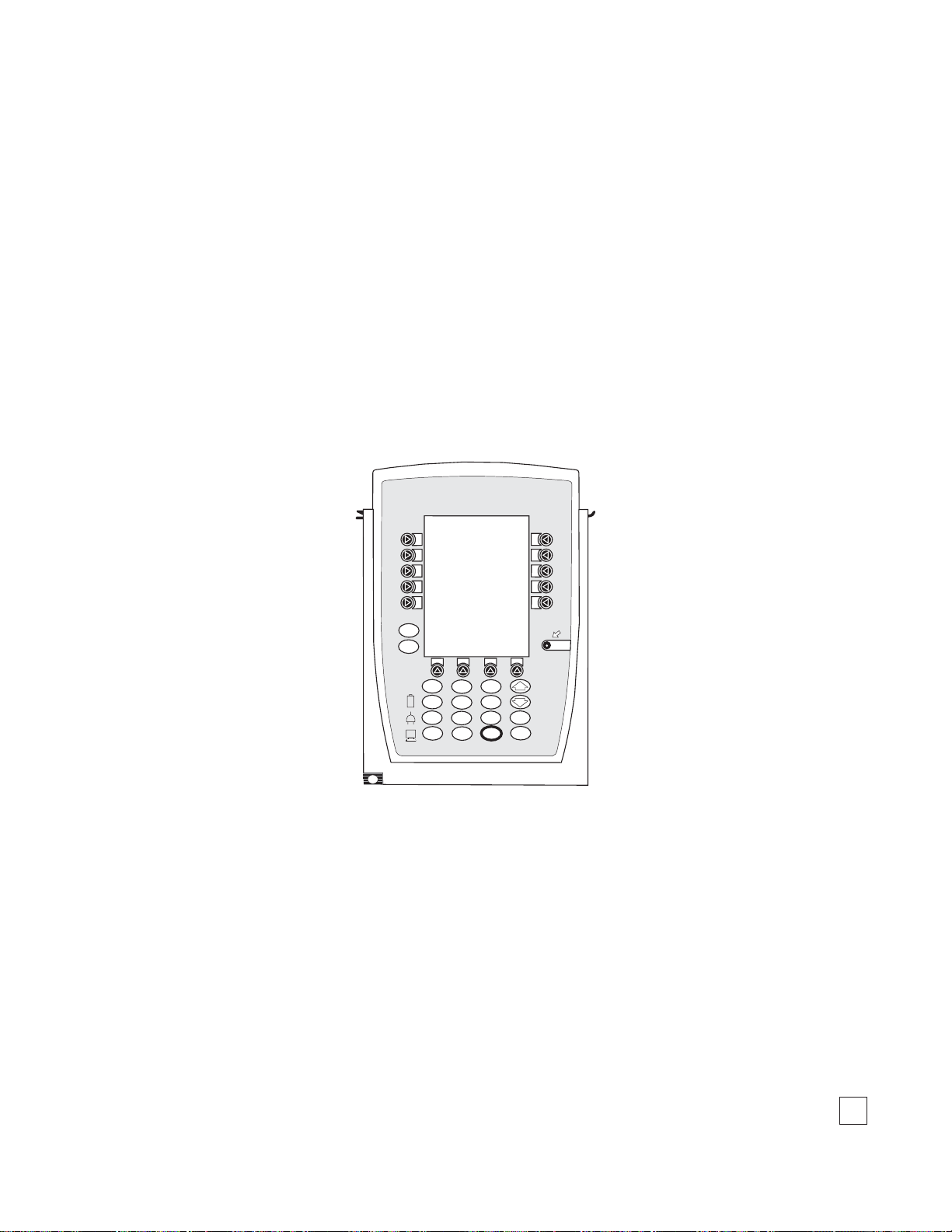
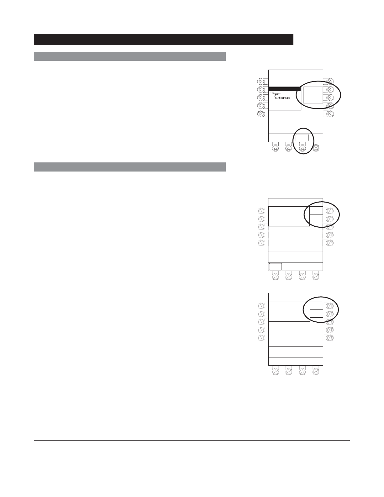
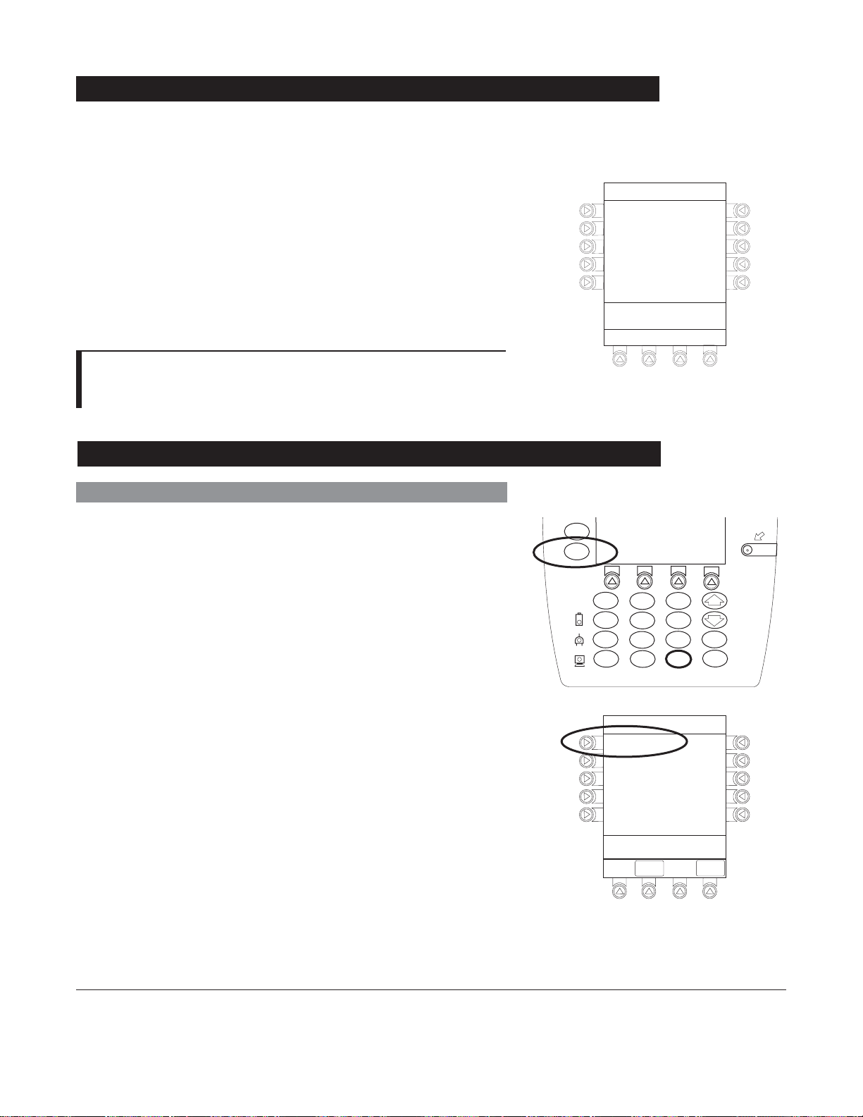
Alaris® PC Unit
Model 8000
SILENCE
OPTIONS
CLEAR
SYSTEM
ON
1
2
4
7
3
6
5
8
0
ENTER
9
CANCEL
.
Alaris® System (with v9 Model 8000) DFU, Section
1


Table of Contents
GETTING STARTED
INTRODUCTION................................................................................................................................................................................................. 1-1
GENERAL SETUP AND OPERATION
ATTACHING AND DETACHING MODULES .......................................................................................................................................... 1-3
Attaching Module(s) ................................................................................................................................................................................ 1-3
Detaching Module(s) ............................................................................................................................................................................... 1-4
Adding Module(s) While System is Powered On
START -UP
.............................................................................................................................................................................................................. 1-5
Powering On System .............................................................................................................................................................................. 1-5
Responding to Maintenance Reminder .......................................................................................................................................... 1-6
Adjusting Display Contrast
................................................................................................................................................................... 1-6
Selecting New Patient and Profile Options ................................................................................................................................... 1-7
Adjusting Audio Volume
........................................................................................................................................................................ 1-9
Locking/Unlocking Tamper Resist .................................................................................................................................................... 1-10
POWER OFF SYSTEM .................................................................................................................................................................................... 1-11
SYSTEM OPTIONS
........................................................................................................................................................................................... 1-11
Display Contrast ....................................................................................................................................................................................... 1-11
Patient ID ..................................................................................................................................................................................................... 1-12
Clinician ID .................................................................................................................................................................................................. 1-14
Power Down All Channels
Anesthesia Mode
Battery Runtime
..................................................................................................................................................................................... 1-16
........................................................................................................................................................................................ 1-19
System Configurations
.................................................................................................................................................................... 1-15
.......................................................................................................................................................................... 1-19
Serial Numbers ......................................................................................................................................................................................... 1-21
Software Versions ................................................................................................................................................................................... 1-22
Time of Day ................................................................................................................................................................................................ 1-23
Network Status ......................................................................................................................................................................................... 1-24
Wireless Connection .............................................................................................................................................................................. 1-26
Data Set Status ......................................................................................................................................................................................... 1-27
Maintenance Due ..................................................................................................................................................................................... 1-28
........................................................................................................................ 1-4
GENERAL INFORMATION
WARNINGS AND CAUTIONS .............................................................................................................................. ........................................ 1-31
General ......................................................................................................................................................................................................... 1-31
Electromagnetic Compatibility ............................................................................................................................................................ 1-32
FEATURES AND DISPLAYS ......................................................................................................................................................................... 1-33
Features and Definitions ....................................................................................................................................................................... 1-33
Operating Features, Controls, Indicators ...................................................................................................................................... 1-35
Displays ........................................................................................................................................................................................................ 1-37
SYSTEM CONFIGURABLE SETTINGS .................................................................................................................................................. 1-38
SPECIFICATIONS AND SYMBOLS ........................................................................................................................................................... 1-39
Specifications ............................................................................................................................................................................................ 1-39
Symbols ....................................................................................................................................................................................................... 1-40
Alaris® System (with v9 Model 8000) DFU
Table of Contents i
PC Unit Section

TROUBLESHOOTING AND MAINTENANCE
GENERAL .............................................................................................................................................................................................................. 1-43
ALARM, ERRORS, MESSAGES
Definitions
................................................................................................................................................................................................... 1-43
Audio Characteristics
Alarms ........................................................................................................................................................................................................... 1-45
Errors............................................................................................................................................................................................................. 1-45
Messages .................................................................................................................................................................................................... 1-46
STORAGE
.............................................................................................................................................................................................................. 1-47
BATTERY CARE AND MAINTENANCE
Battery Type and Charging .................................................................................................................................................................. 1-47
Battery Charge .......................................................................................................................................................................................... 1-48
Battery Care
............................................................................................................................................................................................... 1-48
Battery Cautions and Disposal .......................................................................................................................................................... 1-48
INSPECTION REQUIREMENTS
................................................................................................................................................................. 1-43
............................................................................................................................................................................. 1-44
.................................................................................................................................................. 1-47
................................................................................................................................................................. 1-49
ii Table of Contents
Alaris® System (with v9 Model 8000) DFU
PC Unit Section

Introduction
Getting Started
This Section of the DFU provides PC Unit (Model 8000) and
®
Alaris
System instructions and information. It is used in
conjunction with:
• PC Unit / Pump Module Technical Service Manual
• Product-specific sections of this
• System Maintenance software (and its instructions) for Alaris®
System check-in, maintenance, and wireless configuration
DFU
The PC Unit is the core of the Alaris® System and provides
a common user interface for programming infusions and
monitoring, which helps to reduce complexity at the point of
care.
Alarms, Errors, Messages: See "Troubleshooting and
Maintenance" for specific PC Unit alarms, errors and
messages.
Contraindications: None known.
Electromagnetic Environment: See "Appendix" Section of
this DFU ("Regulations and Standards", "Compliance").
WARNING
Read all instructions, including
those for the attached module(s) and
applicable accessories, before using
®
the Alaris
System.
CAUTION
nly
O
Alaris® System (with v9 Model 8000) DFU
PC Unit Section
Getting Started 1-1

THIS PAGE
INTENTIONALLY
LEFT BLANK
1-2 Getting Started
®
Alaris
System (with v9 Model 8000) DFU
PC Unit Section
General Setup and Operation
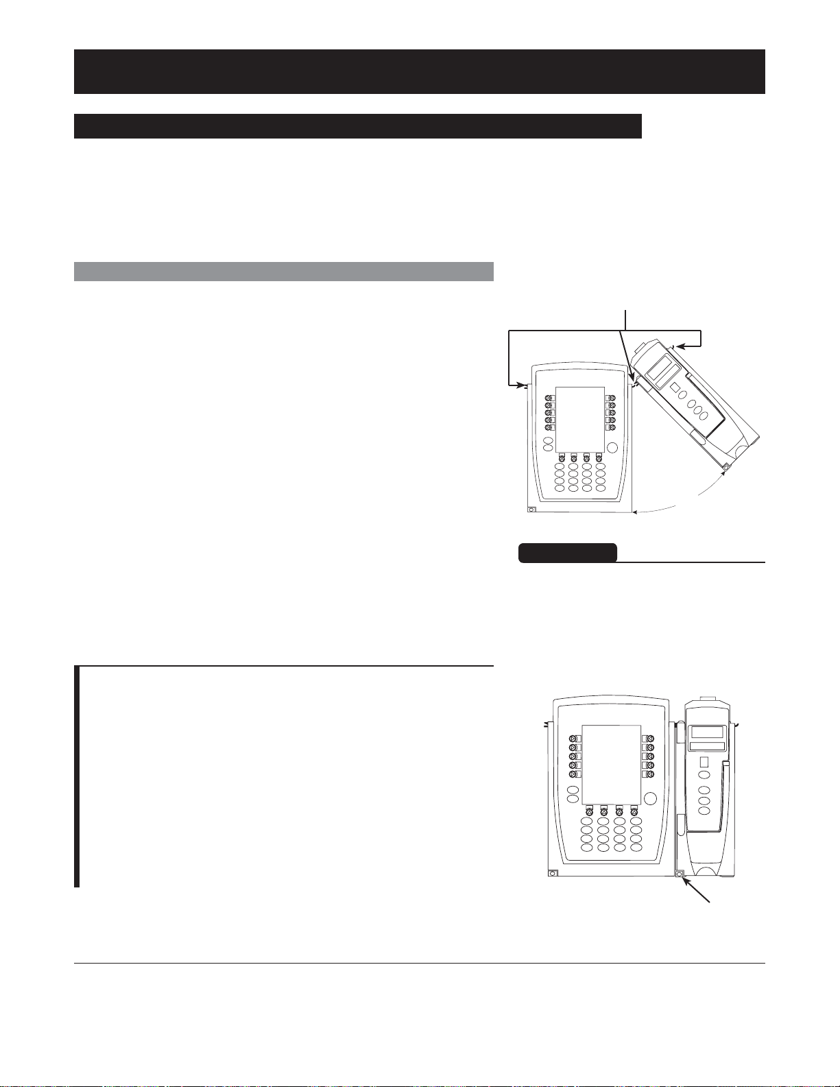
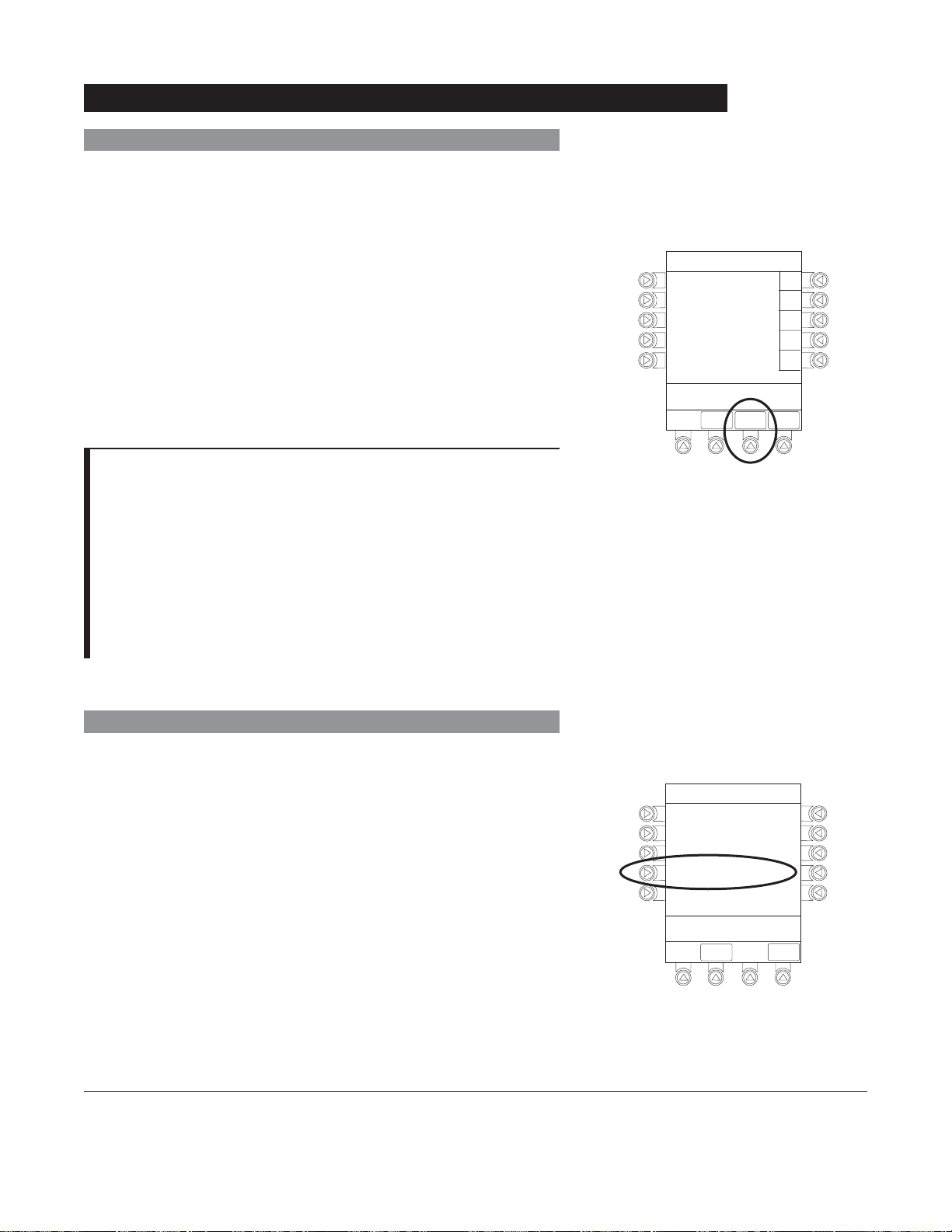
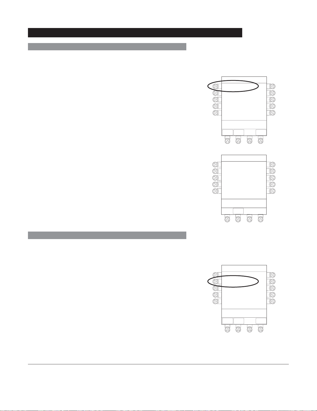
Attaching and Detaching Module(s)
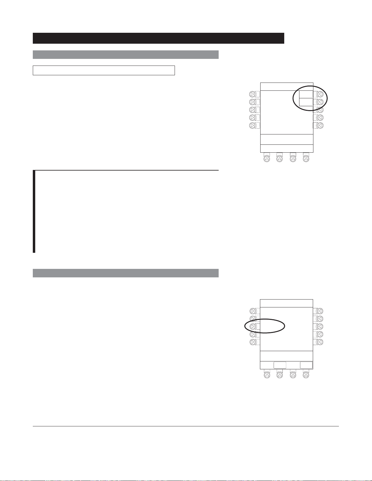
Modules can be attached to either side of the PC Unit or to
either side of another module. The process to attach or detach
is the same for either side, whether attaching/detaching
to/from a PC Unit or another module.
Attaching Module(s)
1. Position free module at a 45° angle, aligning IUI
connectors.
2. Rotate free module down against PC Unit or attached
module, until release latch snaps in place.
IUI Connectors
45°
WARNING
When properly secured/snapped, the
release latch provides a very secure
connection between modules. If not
properly latched, a module can be
dislodged during operation.
NOTES:
Individual hospital/facility may choose to permanently attach
modules. To remove permanently attached modules, contact
qualified service personnel.
Application of adhesive tape or other materials to the sides of
the PC Unit and modules may prevent proper latching.
The Alaris® System is designed to operate a maximum of 4
infusion or monitoring modules. Modules added in excess of
4 are recognized by the system. The Auto-ID Module can be
included as a fifth module. The module(s) can be attached
in any position; however, when mounted on an IV pole, it is
recommended that a balanced configuration be maintained.
Alaris® System (with v9 Model 8000) DFU
PC Unit Section
Release Latch
General Setup and Operation 1-3

Attaching and Detaching Modules (Continued)
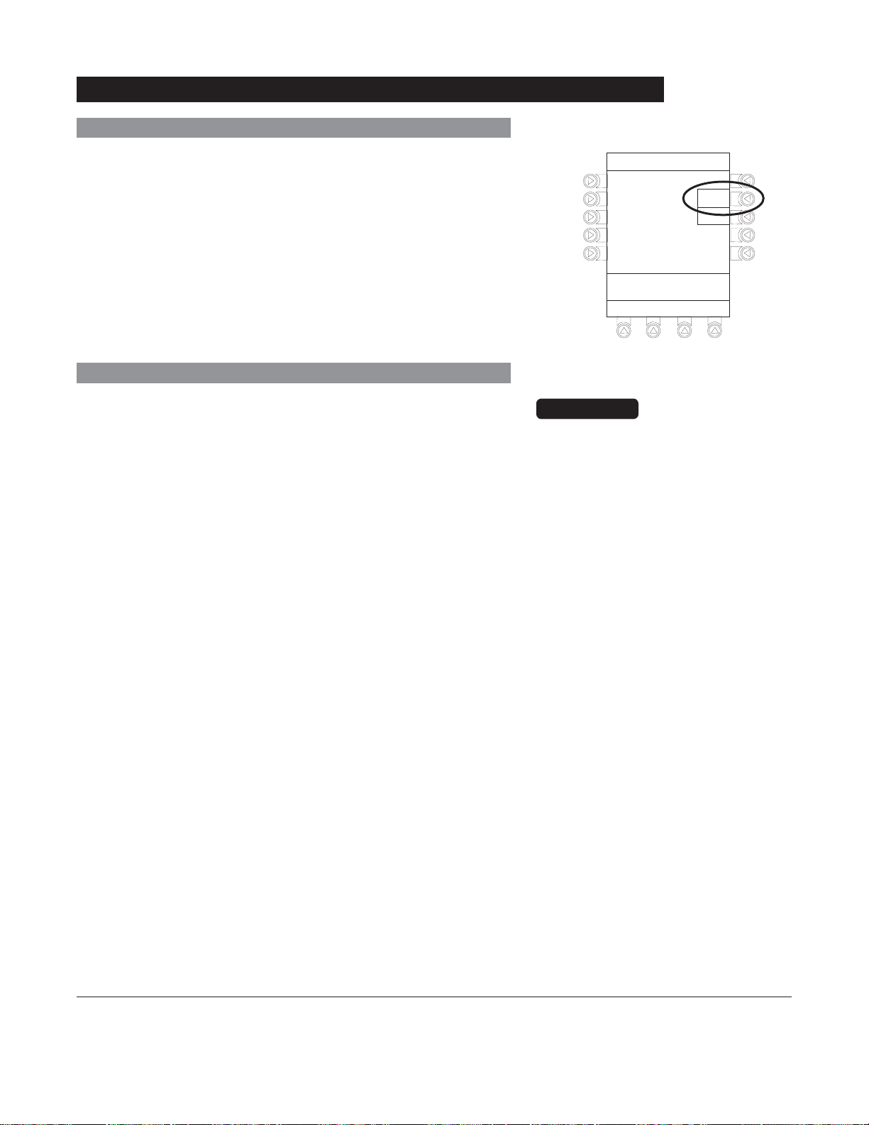
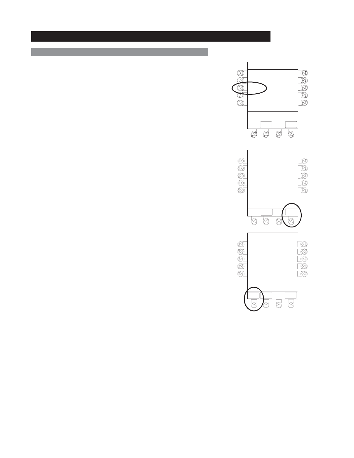
Detaching Module(s)
1. Ensure module(s) is powered off before detaching.
2. Push module release latch and then rotate module(s) up
and away from PC Unit or attached module (opposite to
motion shown above) to disengage connectors.
®
• Alaris
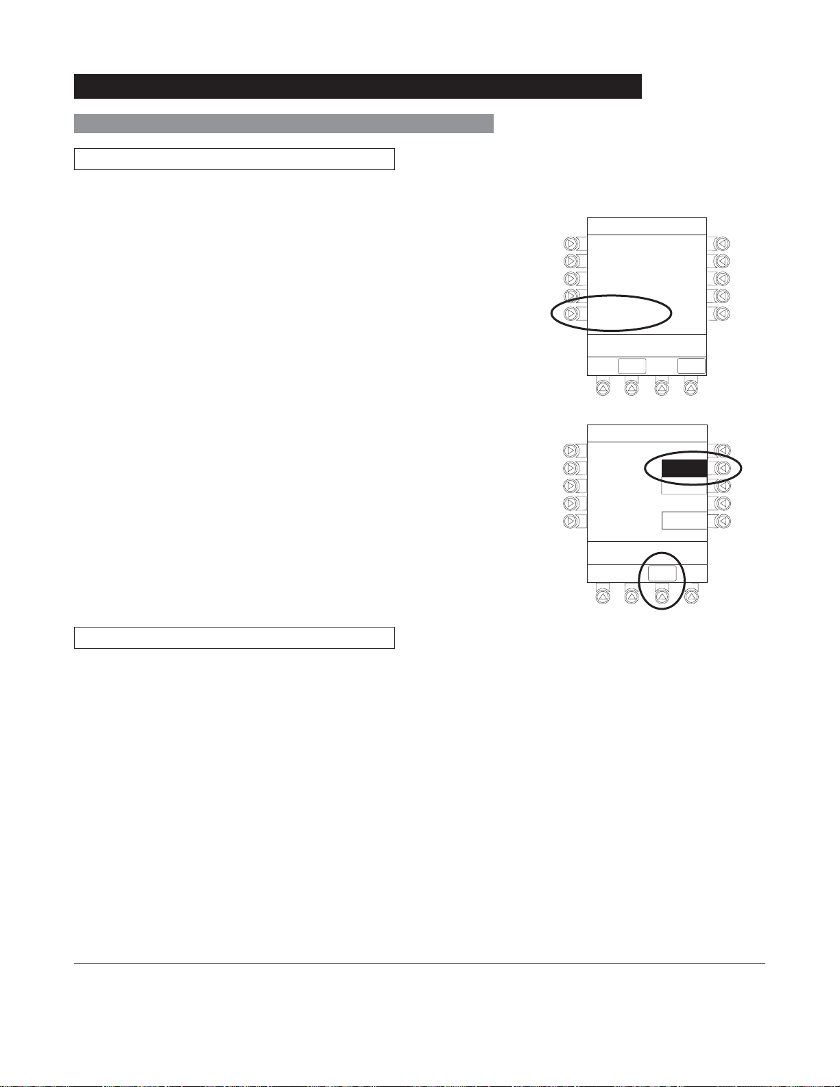
module identification (
• Appropriate module position(s) (
remaining module(s) appear on Main Display.
System reidentifies and shows appropriate
A, B, C or D), from left to right.
A, B or C) for
Adding Module(s) While System is Powered On
Add module as described in "Attaching Module(s)".
• System tests module, causing all
LED segments and
indicator lights of displays to illuminate briefly.
• Appropriate module identification display (
A, B, C or D)
illuminates. Modules are always labeled left to right, so if
a module is added to left of other modules, all modules are
reidentified. Module reidentification does
NOT interrupt or
affect infusion or monitoring on active modules.
• Module positions (
NOTE:
If any of the following conditions are observed, the affected
module must be removed from use and inspected by qualified
personnel:
• LED segments are not illuminated on displays during
power-on test.
• Indicator lights do not illuminate.
• Appropriate module identification (A, B, C or D) is not
displayed.
If the affected module operates normally when it is attached
via the alternate
replacement module can be substituted.
A, B, C or D) appear on Main Display.
IUI connector, it may be used until a
1-4 General Setup and Operation
®
Alaris
System (with v9 Model 8000) DFU
PC Unit Section

Start-Up
Powering On System
1. Connect PC Unit to an external AC power source.
2. Press
SYSTEM ON.
3. System self test begins:
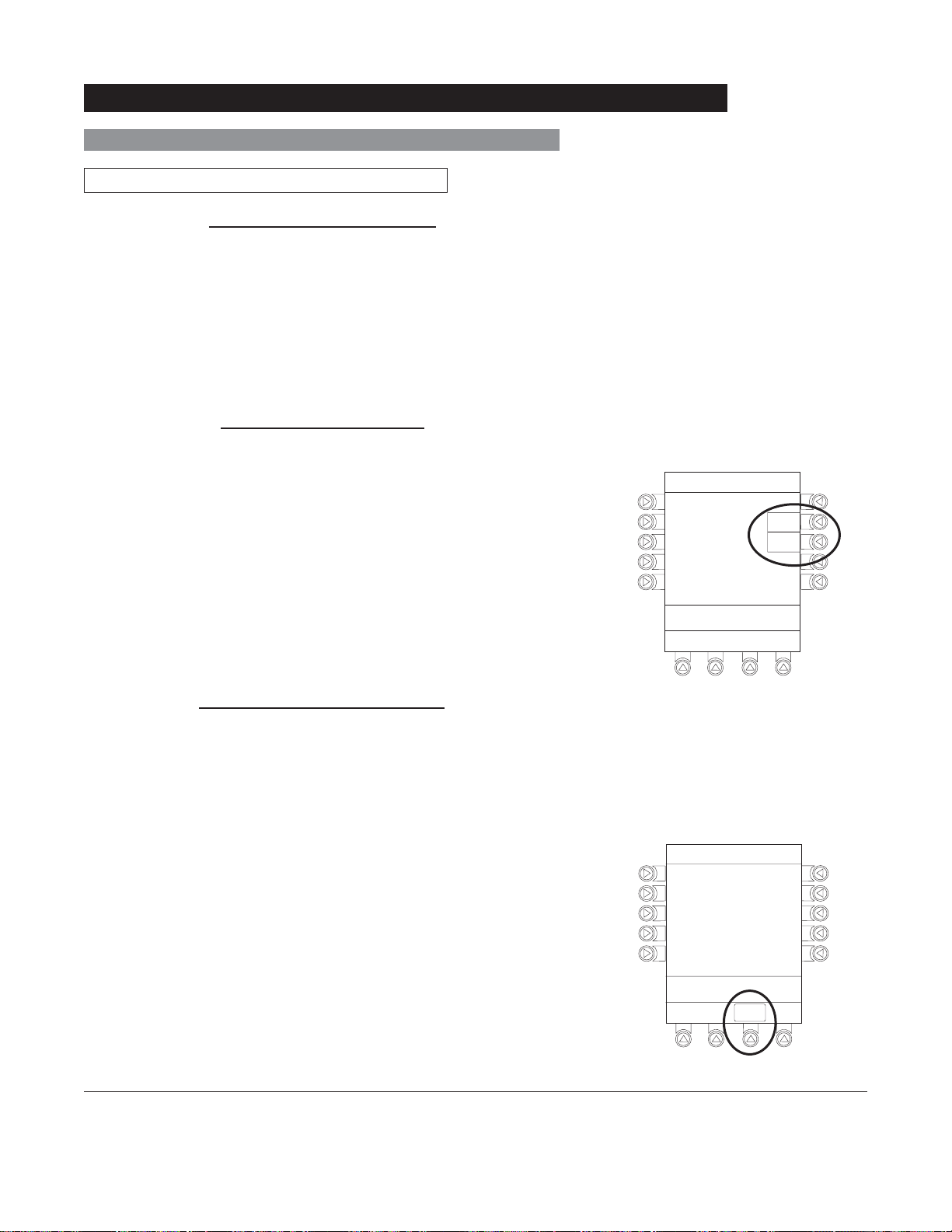
• Diagnostics test causes all LED display segments
and Status Indicator lights of attached module(s) to
illuminate briefly.
• Power Indicator illuminates.
• Appropriate module identification (A, B, C or D)
displays on attached module(s).
• An Audio tone sounds.
• If PM Reminder option is enabled and scheduled
preventive maintenance is due,
REMINDER screen appears.
MAINTENANCE
• At completion of system-on test, New Patient? screen
appears.
NOTES:
Previous infusion parameters are automatically cleared after
8 hours.
If any of the following conditions are observed, the PC Unit or
the affected attached module must be removed from use and
inspected by qualified personnel:
• LED segments are not illuminated during system-on test.
• Indicator lights do not illuminate.
• Appropriate module identification (A, B, C or D) is not
displayed.
• Audio tone does not sound.
• Main Display does not appear backlit, appears irregular, or
has evidence of a row of pixels not functioning properly.
If the affected module operates normally when it is attached
via an alternate IUI connector, it may be used until a
replacement module can be substituted.
Alaris® System (with v9 Model 8000) DFU
PC Unit Section
General Setup and Operation 1-5
Start-Up (Continued)
Responding to Maintenance Reminder
If the Preventive Maintenance (PM) Reminder option is enabled
and the PC Unit or an attached module is due for preventive
maintenance, a
MAINTENANCE REMINDER message appears
at power up.
1. Remove and, if needed, replace module requiring
maintenance with a new module (see "Attaching and
Detaching Modules").
®
2. If Alaris
System was powered off to replace PC Unit,
reinitiate start-up process.
OR
If an attached module (such as a Pump Module) was
powered off and removed,
MAINTENANCE REMINDER
display reflects removal of that module. To continue
start–up process, press
CONFIRM soft key.
MAINTENANCE REMINDER
Module(s) due for routine
B
preventive maintenance:
Module A:
MAINTENANCE REMINDER
Module(s) due for routine
B
preventive maintenance:
YYYY-MM-DD
CONFIRM
CONFIRM
NOTES:
If necessary, the reminder can be temporarily bypassed by
pressing the CONFIRM soft key.
Notify the appropriate facility personnel when a
MAINTENANCE REMINDER occurs.
Adjusting Display Contrast
1. Press DISPLAY CONTRST soft key.
Midtown Hospital
NEW PATIENT ?
“Yes” Clears Previous
Patient Data
>Select Yes or No
DISPLAY
CONTRST
Yes
No
1-6 General Setup and Operation
®
Alaris
System (with v9 Model 8000) DFU
PC Unit Section
Start-Up (Continued)
Adjusting Display Contrast (Continued)
2. To adjust display for optimum viewing, use Lighter/Darker
soft keys.
3. To return to main screen, press CONFIRM soft key.
Selecting New Patient and Profile Options
The following procedures assume the Profiles feature is
enabled.
1. Select required
NEW PATIENT? option.
• To indicate programming is for a new patient and clear
all stored patient parameters from memory, press Yes
soft key.
OR
• To confirm programming is for same patient and retain
all stored patient parameters, press No soft key.
♦ Last used profile displays.
System Options
Display Contrast
®
Guardrails Suite MX (v8)
©2001-2005 Cardinal Health, inc.
or one of itssubsidiaries. All rights
reserved. Guardrails® is a registered
trademark of Cardinal Health, inc. or
one of itssubsidiaries.
>Adjust Display to
Desired Contrast
CONFIRM
Midtown Hospital
NEW PATIENT ?
“Yes” Clears Previous
Patient Data
>Select Yes or No
DISPLAY
CONTRST
Lighter
Darker
Yes
No
2. Accept or change current profile:
• To accept current profile, press Yes soft key.
♦ Main screen appears.
• To change profile, press No soft key and continue with
next step.
♦ Profile selection screen appears.
Alaris® System (with v9 Model 8000) DFU
PC Unit Section
Midtown Hospital
Adult ICU
Adult ICU ?
“Yes” Confirms Same
Profile
>Select Yes or No
Yes
No
General Setup and Operation 1-7
Start-Up (Continued)
Selecting New Patient and Profile Options (Continued)
3. To select a profile, press corresponding left soft key.
4. To confirm profile selection, press CONFIRM soft key.
• Main screen appears.
NOTES:
If the Profiles feature is disabled, the main menu appears.
To view additional choices, press
PAGE DOWN soft key.
Patient ID Entry Feature
The option to enter and display a 16-character alphanumeric
patient identifier is always available. The instrument may
be configured to automatically display the Patient ID Entry
screen during start-up or to provide access only through the
Systems Options menu (see "System Options").
Midtown Hospital
Profiles
Adult ICU
Adult General Care
Neonatal
Peds ICU
Neonatal ICU
>Press CONFIRM
CONFIRM
1of2
PAGE
DOWN
If Yes was selected to indicate programming for a new patient,
perform one of following steps:
• If patient identifier is not required, press
CONFIRM or EXIT
soft key.
• To manually enter patient identifier, use numeric data entry
keys and/or alpha speed keys.
• To scan bar code on patient identification band, see
Auto-ID Module Section of this DFU.
1-8 General Setup and Operation
Patient ID Entry
A
B
C
D
E
________________
>Enter Patient ID and Press
CONFIRM
CONFIRM
EXIT
®
Alaris
System (with v9 Model 8000) DFU
PC Unit Section
A-E
F-J
K-O
P-T
U-Y
PAGE
DOWN
Start-Up (Continued)
Selecting New Patient and Profile Options (Continued)
Patient ID Entry Feature (Continued)
NOTES:
An alphanumeric identifier, of up to 16 characters, can be
entered.
Press the soft key next to a letter group to list letters in that
group. Press the soft key next to an individual letter to enter
that letter.
To access the letter "Z" and special characters (hyphen,
underscore, space), press the PAGE DOWN soft key.
To clear an entire entry, press CLEAR key.
To back up a single character at a time, press
Adjusting Audio Volume
CANCEL key.
1. Press AUDIO ADJUST soft key.
2. To change volume to desired level, press either Louder
or Softer soft key. To sample alarm loudness level, press
Test soft key.
3. To return to PC Unit screen, press
MAIN SCREEN soft key.
• After 30 seconds without a key press, Main Display
appears.
Midtown Hospital
Adult ICU
VTBI = 250.0 mL
VOLUME
INFUSED
Audio Volume Adjust
AUDIO
ADJUST
Test
3
Softer
>Change Setting or
Cancel
Louder
MAIN
SCREEN
Alaris® System (with v9 Model 8000) DFU
PC Unit Section
General Setup and Operation 1-9
Start-Up (Continued)
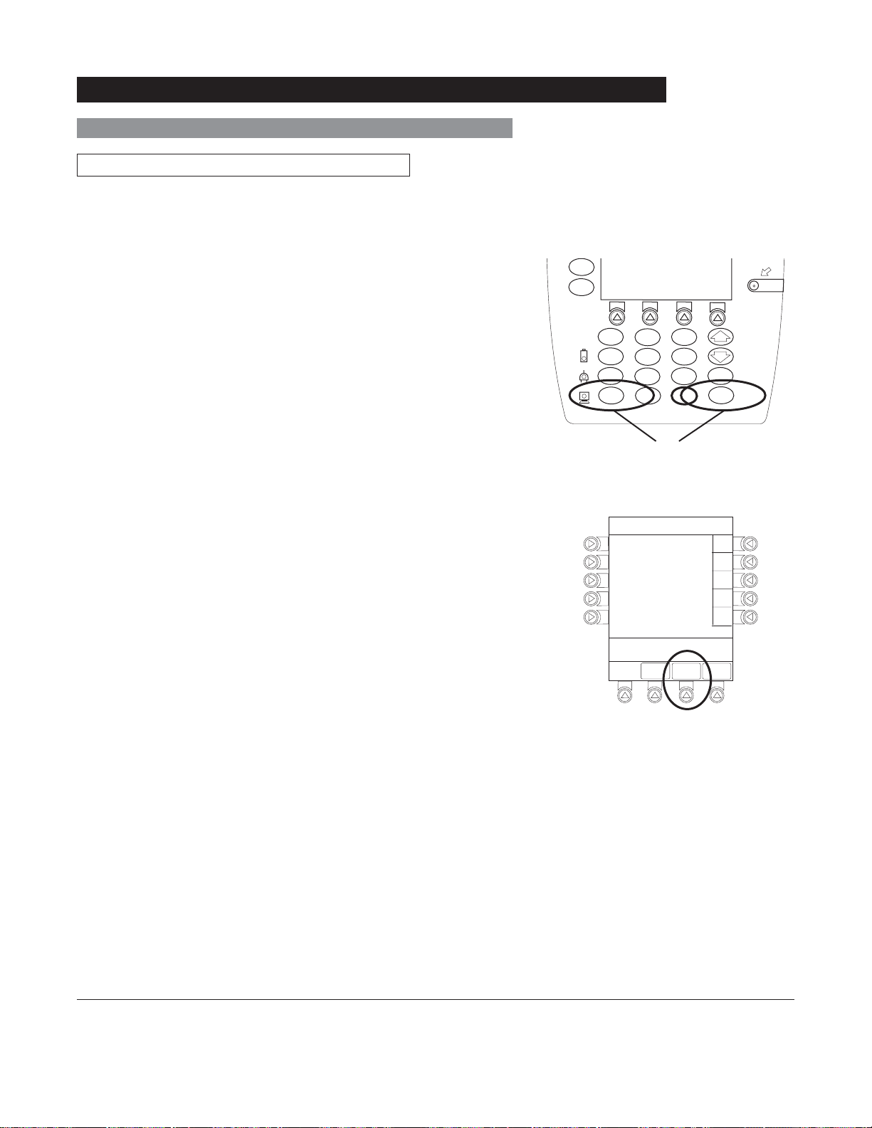
Locking/Unlocking Tamper Resist
1. Initiate operation of applicable module(s).
2. Press and hold Tamper Resist Switch, on back of PC Unit,
3 to 4 seconds (see "General Information", "Features
for
and Displays", "Operating Features, Controls, Indicators").
• An advisory tone (if Key Click Audio is enabled)
and a three-second
PANEL LOCKED prompt on Main
Display confirm activation.
• When Tamper Resist is active, keypad panel is locked;
however, clinician may:
♦ Silence audio alarm.
♦ View volume(s) infused.
♦ View and test audio alarm setting.
♦ View selected parameters on attached modules.
Any other key press results in a visual
PANEL LOCKED
prompt and, if Key Click Audio is enabled, an illegal
key–press audio advisory.
3. To unlock keypad panel, press and hold Tamper Resist
Switch for
3 to 4 seconds.
• An advisory tone (if Key Click Audio is enabled) and
a three-second
PANEL UNLOCKED prompt on Main
Display confirm activation.
Midtown Hospital
Adult ICU
VTBI = 250.0 mL
PANEL LOCKED
VOLUME
INFUSED
Midtown Hospital
Adult ICU
VTBI = 250.0 mL
AUDIO
ADJUST
1-10 General Setup and Operation
PANEL UNLOCKED
VOLUME
INFUSED
®
Alaris
System (with v9 Model 8000) DFU
AUDIO
ADJUST
PC Unit Section
Power Off System
Press and hold CHANNEL OFF key until a beep is heard
(approximately
down.
1.5 seconds) and then release to initiate power
• During power off sequence, Main Display flashes
Powering Down.
• Once all attached modules are powered off, PC Unit
automatically powers down.
NOTE:
To interrupt the power down sequence, quickly press any key
(except SYSTEM ON) on the PC Unit.
System Options
Display Contrast
Powering Down
1. Press OPTIONS key.
2. Press Display Contrast soft key.
3. Adjust display and return to main screen (see "Start-Up",
"Adjusting Display Contrast" procedure).
SILENCE
OPTIONS
1
4
7
CLEAR
System Options 1 of 3
Display Contrast
Patient ID
Clinician ID
Power Down All Channels
Anesthesia Mode
>Select an Option or
EXIT
2
5
8
0
EXIT
SYSTEM
ON
3
6
ENTER
9
CANCEL
.
PAGE
DOWN
Alaris® System (with v9 Model 8000) DFU
PC Unit Section
General Setup and Operation 1-11
Entering
1. Press OPTIONS key.
System Options (Continued)
Patient ID
2. Press Patient ID soft key.
3. Scan or manually enter patient identifier:
• To manually enter patient identifier, use numeric data
entry keys and/or alpha speed keys.
• To scan bar code on patient identification band, see
Auto-ID Module Section of this DFU.
4. To verify correct entry, press
CONFIRM soft key.
System Options 1 of 3
Display Contrast
Patient ID
Clinician ID
Power Down All Channels
Anesthesia Mode
>Select an Option or
EXIT
EXIT
Patient ID Entry
A
B
C
D
E
123456789CD_____
>Enter Patient ID and Press
CONFIRM
EXIT
CONFIRM
PAGE
DOWN
A-E
K-O
P-T
U-Y
PAGE
DOWN
F-J
1-1 2 General Setup and Operation
®
Alaris
System (with v9 Model 8000) DFU
PC Unit Section
System Options (Continued)
Patient ID (Continued)
Modifying
1. Press OPTIONS key.
2. Press Patient ID soft key.
3. To clear entire entry, press
CLEAR key.
OR
To back up a single character at a time, press CANCEL
key.
4. To enter modified patient identifier, use numeric data entry
keys and/or alpha speed keys.
5. To verify correct entry, press CONFIRM soft key.
• New Patient ID Entry verification screen appears.
SILENCE
OPTIONS
1
4
7
CLEAR
Patient ID Entry
A
B
C
D
E
234567891EF_____
>Enter Patient ID and Press
CONFIRM
2
5
8
0
EXIT
OR
3
6
9
.
CONFIRM
ENTER
CANCEL
A-E
F-J
K-O
P-T
U-Y
PAGE
DOWN
SYSTEM
ON
Alaris® System (with v9 Model 8000) DFU
PC Unit Section
General Setup and Operation 1-13
Patient ID (Continued)
Modifying (Continued)
System Options (Continued)
6. To accept modified Patient ID, press Yes soft key.
• Main screen appears with new Patient ID.
OR
To retain original (old) Patient ID, press No soft key.
• Main screen appears with old Patient ID.
NOTES:
An alphanumeric identifier, of up to 16 characters, can be
entered.
Press the soft key next to a letter group to list letters in that
group. Press the soft key next to an individual letter to enter
that letter.
To access the letter "Z" and special characters (hyphen,
underscore, space), press the PAGE DOWN soft key.
To clear an entire entry, press CLEAR key.
To back up a single character at a time, press CANCEL key.
Patient ID Entry
Patient ID
123456789CD
will be changed to
234567891EF
Is this correct?
>Press Yes or No
Yes
No
Clinician ID
1. Press OPTIONS key.
2. Press Clinician ID soft key.
1-14 General Setup and Operation
System Options 1 of 3
Display Contrast
Patient ID
Clinician ID
Power Down All Channels
Anesthesia Mode
>Select an Option or
EXIT
EXIT
®
Alaris
System (with v9 Model 8000) DFU
PC Unit Section
PAG E
DOWN
System Options (Continued)
Clinician ID (Continued)
3. Scan or manually enter clinician identifier:
• To manually enter clinician identifier, use numeric data
entry keys and/or alpha speed keys.
4. To verify correct entry, press CONFIRM soft key.
NOTES:
An alphanumeric identifier, of up to 16 characters, can be
entered.
Press the soft key next to a letter group to list letters in that
group. Press the soft key next to an individual letter to enter
that letter.
To access the letter "
underscore, space), press the PAGE DOWN soft key.
To clear an entire entry, press CLEAR key.
To back up a single character at a time, press CANCEL key.
Z" and special characters (hyphen,
Clinician ID Entry
CONFIRM
A-E
F-J
K-O
P-T
U-Y
PAGE
DOWN
A
B
C
D
E
123456789CD_____
>Enter Clinician ID and Press
CONFIRM
EXIT
Power Down All Channels
1. Press OPTIONS key.
2. Press Power Down All Channels soft key.
Alaris® System (with v9 Model 8000) DFU
PC Unit Section
System Options 1 of 3
Display Contrast
Patient ID
Clinician ID
Power Down All Channels
Anesthesia Mode
>Select an Option or
EXIT
EXIT
PAG E
DOWN
General Setup and Operation 1-15
System Options (Continued)
Power Down All Channels (Continued)
3. Press Yes soft key.
• During power off sequence, Main Display flashes
POWERING DOWN.
Anesthesia Mode
When the Anesthesia Mode is enabled while a module is
paused, the module remains in an indefinite pause until
restarted.
When Anesthesia Mode is enabled:
• All limits are set to Soft.
• Dose checking mode is set to Smart.
• Key-press audio is turned off.
• Tamper Resist Mode (panel locked) is not available.
®
• Guardrails
Software as anesthesia only. All Guardrails
profile can be viewed by pressing
drug list defaults to drugs designated by Editor
®
drugs in a
ALL DRUGS soft key.
System Options
Power Down
All Channels?
>Press Yes or No
Yes
No
CAUTION
When the Alaris® System is set up
for use in Anesthesia Mode, it is
important to select the profile that
corresponds with the care area the
patient will be taken to when the
Anesthesia Mode is discontinued.
®
This ensures that the Alaris
System
will be in the correct profile following
the use of the Anesthesia Mode.
• Bolus dose is automatically available for:
♦ Guardrails
♦ generic drug calculation setup
®
drugs that have bolus dose limits defined
• Anesthesia Mode, alternating with other required prompts,
displays in prompt bar of Main Display.
• Callback audio for paused module is permanently silenced.
• Review of drug calculation setup page is omitted when
restoring a stopped drug calculation.
• Clinical Advisories are not displayed.
• Auto-ID Module is not available.
1-16 General Setup and Operation
®
Alaris
System (with v9 Model 8000) DFU
PC Unit Section
Anesthesia Mode (Continued)
Enabling
1. Press OPTIONS key.
System Options (Continued)
2. Press Anesthesia Mode soft key.
3. Press Enable soft key.
4. Press
CONFIRM soft key.
System Options 1 of 3
Display Contrast
Patient ID
Clinician ID
Power Down All Channels
Anesthesia Mode
>Select an Option or
EXIT
EXIT
System Options
Anesthesia Mode
Pump Module
Air Detection =
75
microliters
>Select an Option or Press
CONFIRM
CONFIRM
PAGE
DOWN
Enable
Disable
Change
Disabling
The Anesthesia Mode can be disabled, and normal operation
resumed, using either of the following three methods:
• System Options menu.
• Disconnecting from
AC power.
• Connecting to AC power.
Alaris® System (with v9 Model 8000) DFU
PC Unit Section
General Setup and Operation 1-1 7
Anesthesia Mode (Continued)
Disabling (Continued)
From System Options Menu
System Options (Continued)
1. Press
OPTIONS key.
2. Press Anesthesia Mode soft key.
3. Press Disable soft key.
4. Press
CONFIRM soft key.
• Anesthesia Mode no longer appears on Main Display,
indicating it has been disabled.
Connecting To AC Power
1. Connect system to
AC power.
2. To continue using Anesthesia Mode, press Yes soft key.
OR
To discontinue Anesthesia Mode, press No soft key.
AC power cord was
connected.
Continue
>Select Yes or No
Yes
No
?ANESTHESIA MODE
Disconnecting from AC Power
1. Disconnect system from
AC.
• Anesthesia Mode is automatically disabled.
• All currently running infusions continue.
• A prompt appears as an alert that Anesthesia Mode
has been discontinued.
2. Press
CONFIRM soft key.
1-18 General Setup and Operation
Anesthesia mode was
when AC power
disconnected.
continue normal operation.
>Press CONFIRM
®
Alaris
System (with v9 Model 8000) DFU
discontinued
cord was
Press CONFIRM to
CONFIRM
PC Unit Section
Battery Runtime
1. Press OPTIONS key.
System Options (Continued)
2. Press
PAGE DOWN soft key.
3. Press Battery Runtime soft key.
4. To return to main screen, press CANCEL key or EXIT soft
key.
System Options 2 of 3
Battery Runtime
System Configurations
Serial Numbers
Software Versions
Time of Day
>Select an Option or
EXIT
PAGE UP
EXIT
PAGE
DOWN
System Options
Estimated battery
runtime at current
operating parameters
9.5
hours
>Press CANCEL or EXIT
EXIT
System Configurations
1. Press OPTIONS key.
2. Press
PAGE DOWN soft key.
3. Press System Configurations soft key.
Alaris® System (with v9 Model 8000) DFU
PC Unit Section
System Options 2 of 3
Battery Runtime
System Configurations
Serial Numbers
Software Versions
Time of Day
>Select an Option or
EXIT
PAGE UP
EXIT
PAGE
DOWN
General Setup and Operation 1-19
System Options (Continued)
System Configurations (Continued)
4. Press PC Unit soft key.
5. To review various system configuration settings, press
PAGE DOWN and PAGE UP soft keys.
System Configuration - Module
Factory Default:
Shared Infusion Settings
PC Unit
Pump Module
SPO2 Module
>Press CANCEL or EXIT
EXIT
System Config - PCU 1 of 3
Alarm audio:
Anesthesia Mode: Disabled
Battery meter:
Clock setup:
Limit Checking:
>Press CANCEL or EXIT
EXIT
Yes
PAGE
DOWN
Profile 1
Disabled
09:00
ALWAYS
PAGE
DOWN
System Config - PCU 2 of 3
Key click audio:
Max Pt. BSA:
Max Pt. weight:
Patient ID Entry:
Pending IV Orders:
>Press CANCEL or EXIT
PAGE
EXIT
UP
Enabled
2
2m
500 kg
Disabled
Enabled
DOWN
PAGE
1-20 General Setup and Operation
®
Alaris
System (with v9 Model 8000) DFU
PC Unit Section
 Loading...