

Cardinal Health 225 User manual

CHECK WEIGHER
For The 225 Weight Indicator
Installation, Setup and Operation Manual
8200-M564-O1 Rev A PO BOX 151 y WEBB CITY, MO 64870 Printed in USA
08/09 PH (417) 673-4631 y FAX (417) 673-5001
www.cardinalscale.com
8200-M564-O1 y 225 Check Weigher
Technical Support: Ph: 866-254-8261 y techsupport@cardet.com
Page 1

8200-M564-O1 y 225 Check Weigher
Page 2
INSTALLATION
Logic Level Output
Your Model 225 indicator has logic level outputs that can be used to control peripheral devices
used to signal when the weight is within preset limits. Note that these outputs (defined on the
next page) are at logic level and cannot drive external devices directly. Solid-state relays can
be used to accept the logic level output from the 225 and in turn, drive the external device.
Output Cable Installation
1. If the rear panel of the indicator has been removed, proceed to step 2. Otherwise,
remove the 14 acorn nuts securing the rear panel to main housing
2. Loosen a gland connector for the cable.
3. Slip the cable through the gland connector and into the enclosure.
4. Remove 2 inches of the cable outer insulation jacket
5. Next, remove 1/4 inch of insulation from each of the wires.
6. Connect each of the wires to the Remote Outputs terminal block (P15).
7. To terminate a wire, use a small flat blade screwdriver and press down on the release
bar for the terminal. Insert the wire into the terminal opening. Remove the screwdriver,
allowing the release bar to return to its original position, locking the wire in place.
8. Repeat procedure until all wires are in place.
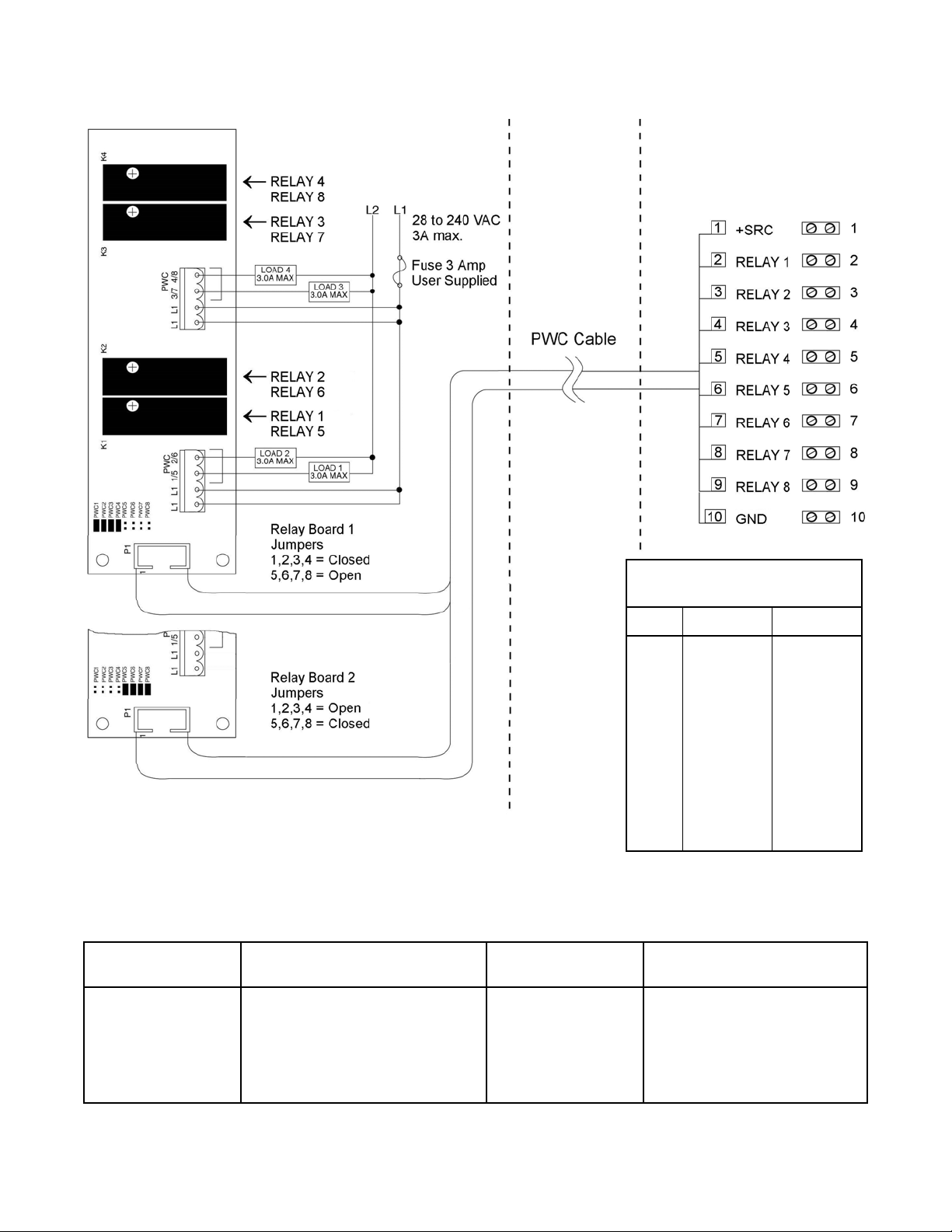
AC Output Relay Board(s)
The AC Output Relay Boards are mounted in an external junction box for use with the 225
Indicator. The RB4-ACOUT contains one board and supports four outputs (jumper selectable).
The RB8-ACOUT contains two boards and supports eight outputs. The relay board used in
both is (Cardinal p/n 8539-C062-0A). Connect the devices to be controlled as shown in Figure
No. 1.
The individual relays can be configured to be on (closed) or off (open) at weights under the
preset weight then switch at the preset weight from on-to-off or off-to-on by setting the under
weight condition to on or off during setup and calibration or setup review.
OUTPUT (closed) 28-240VAC @ 3A maximum for each plug-in relay
CONTROL INPUT 5VDC @ 12mA from the 225 main pc board assembly P8
CONNECTION Removable plug-in screw terminals for up to 14 AWG wire
NOTE! All relays are the normally-open type that will open when power to indicator is lost.
8200-M564-O1 y 225 Check Weigher
Page 1
AC Output Relay Board(s), Cont.
225 Indicator – P15
CHECKWEIGHER
Relay Board
P15 3 Zone 5 Zone
Under Under
Accept Lo Under
Over Accept
Lo Over
Over
Relay Box Assembly RB4-ACOUT or RB8-ACOUT
Figure No. 1
2
3
4
5
6
7
8
9
Relay Box Cable Wire Number to Relay Number Table
The relay box cable wire numbers correspond to the 225 indicator P15 terminal connections.
CABLE WIRE
NUMBER
1 +SRC (For AC Input Relays) 6 5
2 1 7 6
3 2 8 7
4 3 9 8
5 4 10 GND
RELAY NUMBER
(Set Proper Jumpers)
CABLE WIRE
NUMBER
RELAY NUMBER
(Set Proper Jumpers)
8200-M564-O1 y 225 Check Weigher
Page 2
OPTICALLY ISOLATED REMOTE INPUTS
The Model 225 has seven (7) programmable inputs that may be used to remotely (up to 100
feet) initiate various functions within the indicator. These inputs are accessed via a terminal
block (P17) on the back of the Main PC board. The 7 inputs are defined on the following page.
Remember that the input must be connected to GND to initiate the function.
Input Cable Installation
1. If the rear panel of the indicator has been removed, proceed to step 2. Otherwise,
remove the 14 acorn nuts securing the rear panel to main housing
2. Loosen a gland connector for the cable and slip the cable through the gland connector
and into the enclosure.
3. Remove 2 inches of the cable outer insulation jacket and then remove 1/4 inch of
insulation from each of the wires.
4. Connect each of the wires to the Remote Input terminal block (P17).
5. To terminate a wire, use a small flat blade screwdriver and press down on the release
bar for the terminal. Insert the wire into the terminal opening. Remove the screwdriver,
allowing the release bar to return to its original position, locking the wire in place.
6. Repeat procedure until all wires are in place.
AC Input Relay Board(s)
The AC Input Relay Board(s) are mounted in an external junction box for use with the 225
Indicator. The RB4-ACIN (115 VAC) or RB4-ACINV (230 VAC) contain one board and
supports 4 inputs (jumper selectable). The RB8-ACIN (115 VAC) or RB8-ACINV (230 VAC)
contain two boards and supports seven inputs that are jumper selectable. The relay board
used in the 115 VAC versions is Cardinal p/n 8200-C324-0A. The 230 VAC version uses relay
board Cardinal p/n 8200-C324-1A. Connect the devices as shown in Figure No. 2.
INPUT RELAY TYPE IAC-5 90 to 140 VAC @ 6mA maximum for each plug-in relay
INPUT RELAY TYPE IAC-5A 180 to 280 VAC @ 6mA maximum for each plug-in relay
OUTPUT 5VDC @ 12mA from the 225 main pc board assembly P9
12VDC @ 12mA maximum from external source
CONNECTION Removable plug-in screw terminals for up to 14 AWG wire
NOTE! AC INPUT RELAYS ARE VOLTAGE DEPENDENT.
A DIFFERENT RELAY IS REQUIRED FOR 115 VAC AND 230 VAC!
8200-M564-O1 y 225 Check Weigher
Page 3
 Loading...