

Cardinal Detecto 6437, Detecto 6447, Detecto 6439, Detecto 6449, Detecto 6437KG Operating Instructions Manual
...Page 1

Technical Support: Ph: 866-254-8261 v techsupport@cardet.com
PHYSICIAN’S SCALE
Eye-Level Digital Scale
Operating Instructions for
Models 6437, 6439, 6447, 6449
6437KG and 6439KG
CARDINAL SCALE MFG. CO.
0033-M114-O1 Rev E
PO Box 151 v Webb City, MO 64870
03/06
Ph: 417-673-4631 v Fax: 417-673-5001
Printed in USA
www.detectoscale.com
Page 2

2
Page 3
Opening
Abertura
Column Bracket
Soporte de la
columna
4
1
3
2
5
Detecto Physician’s
Scale
Assembly
Instructions
This precision
instrument is extremely
easy to setup as all
major parts are factory
pre-assembled. Before
starting to assemble,
please unpack carefully
and remove all
wrappings and fillers.
Carton contains:
1) Column with head.
2) Platform base.
3) Hand post. optional
4) Height measuring
rod. - optional
5) Screws and
lockwashers.
6) Wheels - optional
1
2
Balanza para médicosInstrucciones de
armado
Este instrumento de
precisión es facilísimo
de armar ya que todos
los componentes
principales son
ensamblados de
antemano en la fábrica.
Antes de empezar, favor
de desempacar
cuidadosamente y
quitar todas las
envolturas y material de
empaque. La caja
contiene:
1) Columna con
cabezal;
2) Plataforma con
base;
3) Poste de Mano;
4) Vara de medir;
5) Tornillos y arandelas
de seguridad;
6) ruedas - opcional
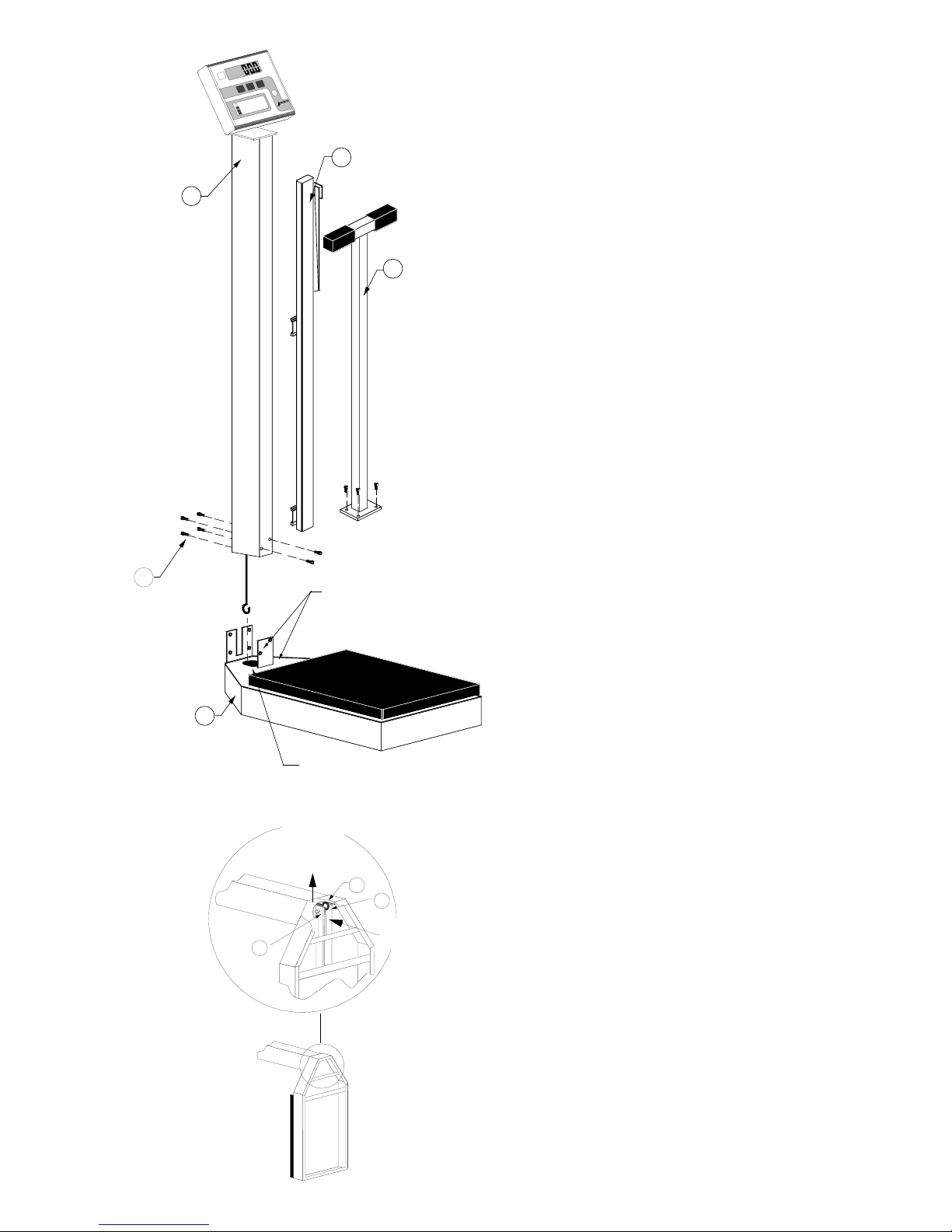
NOTE! If column
bracket is bent,
straighten before
assembling.
Slip column over
column bracket on
platform base. Hold
column straight so that
draft rod enters
opening in column
bracket. Screw column
to column brackets (two
1/4 truss head screws
in front of column, four
in back).
! Si el soporte esta
doblado enderescalo
antes de ensamblar la
balanza.
Pasar la columna por
encima del soporte de
la columna en la base
de la plataforma.
Sostener recta la
columna para que la
vara de acero entre en
la abertura del soporte
de la columna. Atornillar
la columna a sus
soportes (2 tornillos 1/420 adelants, 4 atrás).
3
Lay down scale, with
column horizontal to
floor (using a table top).
1) Raise draft rod
keeping out of
lever’s way.
2) Push lever.
3) When lever is in
position, hook draft
rod around pivot.
Poner la balanza
horizontalment sobre
una mesa.
1) Levantar la vara de
acero manteniendola
alejada de la
palanca.
2) Empujar la palanca.
3) Cuando la palanca
este en posición,
enganche la vara de
acero alrededor del
pivote.
Raise
draft
rod
Push
lever
2
3
1
Page 4

4
758C Operation
Press the ON/OFF key to turn the indicator on. With the display on, press the ZERO key to zero the
weight display. Press the lb/kg key to change the weight units from pounds to kilograms or from
kilograms to pounds. Step onto the scale platform and remain motionless until your weight is
displayed and the stable (><) annunciator is on. Step off the scale and prepare for the next weighing
operation or press the ON/OFF key to turn the indicator off.
Refer to the 758C Owner’s Manual, 8555-M210-O1, for additional information.
758C Oprima
Oprima la tecia ON/OFF para encender el indicador. Oprima la tecla ZERO para establizar el
indicador a zero. Para cambiar la unidad de peso de libras a kilogramos o viceversa oprima la tecla
lb/kg. Suba a la plataforma de la balanza y permanezca inmóvil hasta que su peso es indicado y la
señal de estabilidad (><) aparezca en el indicador. Baje de la balanza y prepare la misma para la
próxima operción u oprima la tecla ON/OFF para apagar la unidad.
Para más información, refierase al manual de operación del indicador 758C número
8555-M210-O1.
Page 5

5
Optional Hand Post
Use the four screws to attach the hand post to the platform
base.
Use cuatro (4) tornillos para pegar el poste de mano a la
base de la plataforma.
6
Optional Wheels
How to setup the Detecto
Physician’s scale with roller
wheels.
Use the two screws in the back
of the column to attach the
wheel bracket.
Como armar la balanza Detecto para médicos con ruedas.
Use los dos tomillos en la parte posterior de la columna
para pegar el soporte de la rueda a la columna.
Screws and
wheel bracket
A
B
C
D
G
E
F
H
5
2
E
N
T
E
R
8
4
1
0
7
6
3
9
C
L
E
A
R
L
O
C
K
U
N
I
T
S
Z
E
R
O
R
E
L
E
A
S
E
O
N
C
A
P
A
C
I
T
Y
O
F
F
I
D
H
E
I
G
H
T
N
E
T
T
A
R
E
G
R
O
S
S
T
D
E
T
C
O
E
A
D
i
v
i
s
i
o
n
o
f
C
a
r
d
i
n
a
l
S
c
a
l
e
M
a
n
u
f
a
c
t
u
r
i
n
g
C
o
.
7 Optional Height Rod
A = “Read” line
B = Spoon
C = Inner height rod
D = Outer height rod
E = Hex head screw
F = Column
G = Mounting bracket
H = Height rod sits on top of the scale base
Opcional Varilla Medidora
A = Linea de lectura
B = Cuchara
C = Varilla medidora interna
D = Varilla medidora externa
E = Tornillos de cabezas hexagonales
F = Columna
G = Soporte
H = La varilla medidora debe descansar sobre
la base
Page 6

Operational Height Rod Installation:
1. Remove the cardboard insert from the height
rod.
2. If not already installed, insert the two hex
head screws from the hardware pack into the
holes in the front of the column and tighten
them with the included wrench until the hex
heads are 1/8" from the column.
3. Place both height rod brackets over the two
pre-installed hex head screws and pull down.
4. Use the included wrench to tighten both hex
head screws. Do not overtighten the screws.
Height Rod Operating Guide:
1. Before the person steps onto the scale
platform, the spoon should be rotated to the
horizontal position, and raised well above the
person’s apparent height.
2. The person may now step onto the scale
platform. The spoon should be held
horizontal and above the person’s head.
3. Carefully lower the spoon, while keeping it
horizontal, until it rests gently upon the top of
the person’s head. If the person is shorter
than 3' 4" (101.5 cm), push the latch to the
right, while simultaneously pushing down on
the spoon, until the spoon rests horizontally
upon the top of the person’s head.
4. Read the height of the person as follows:
If the back of the spoon points to the outer
height rod, then it points to the correct height.
If the back of the spoon points to the inner
height rod, then the correct height is read at
the top of the outer height rod (see “Read”
arrow on the outer height rod).
5. While holding the spoon horizontally, raise
the spoon above the person’s head. The
person may now step off of the scale
platform. Hold the spoon horizontal until the
person is clear of the height rod.
6. Rotate the spoon back to the vertical position
and adjust the height rod back to the rest
position (i.e. the spoon should be locked in
place within the inner height rod and the
inner rod should be at its lowest position).
Instalacion de la Barra Medidora de Altura:
1. Remueva el retenedor de carton de la barra
medidora.
2. Si no estan instalados, coloque los tornillos
con cabezas hexagonales en los huecos al
frente de la columna y atornillelos con la
llave incluida en el paquete de partes, hasta
que sus cabezas quenden aproximadamente
1/8" de pulgada (3mm) de la columna.
3. Coloque los dos soportes de la barra
medidora en los tornillos ya instalados y tire
de los soportes hacia abajo.
4. Termine de atornillar sin apretarlos
demasiado.
Como Usar La Barra Medidora:
1. Antes de subir a la plataforma, la cuchara
debe rotarse hacia la posicion horizontal y
colocarse a una altura superior a la que
aparenta la persona.
2. La persona ya puede subir a la plataforma y
la cuchara debe mantenerse horizontalmente
sobre la cabeza.
3. Bajando la cuchara cuidadosa y
horizontalmente, deje que caiga suavemente
sobre la cabeza. Si la altura de la persona es
menos de 3 pies y 4 pulgadas (101.5 cm),
empuje el pestillo hacia la derecha al mismo
tiempo que empuja la cuchara hacia abajo
hasta que la cuchara descanse sobre la
cabeza de la persona.
4. Lea la altura de la persona de la siguiente
manera:
Si la parte posterior de la cuchara señala
hacia la barra medidora exterior, esta
indicando la altura correcta.
Si la parte posterior de la cuchara señala
hacia la barra medidora interior, entonces
la lectura correcta debe hacerse al tope
de la barra medidora exterior (note la flecha
y la palabra “Read” en la barra medidora
exterior).
5. Mientras mantiene la cuchara en la posicion
horizontal, levantela de la cabeza de la
persona. La persona ya puede bajarse de la
plataforma. Mantenga la cuchara
horizontalmente hasta que la persona haya
bajado de la balanza.
6. Rote la cuchara hacia la posicion vertical y
ajuste la barra medidora en su posicion de
descanso (la cuchara debe estar firme en su
lugar y dentro de la barra medidora interna y
esta debe estar en su posicion mas baja).
Page 7

35
30
29
48
23
37
39
22
38
21
27
24
24
33
1
20
36
6
7
42
43
45
5
2
E
N
T
E
R
8
4
1
0
7
6
3
9
C
L
E
A
R
L
O
C
K
U
N
I
T
S
Z
E
R
O
R
E
L
E
A
S
E
O
N
C
A
P
A
C
I
T
Y
O
F
F
I
D
H
E
I
G
H
T
N
E
T
T
A
R
E
G
R
O
S
S
T
D
E
T
C
O
E
A
D
i
v
i
s
i
o
n
o
f
C
a
r
d
i
n
a
l
S
c
a
l
e
M
a
n
u
f
a
c
t
u
r
i
n
g
C
o
.
Item Part Number Description
Req’d
1 758C Weight Indicator 1
(see manual)
6 728R90 Power Supply,
115 VAC 60 Hz 1
729R901 Power Supply,
230 VAC 50 Hz 1
7 0033-B163-0A Bracket 1
20 0044-C180-1A Column Assy 1
21 3P8059 Union Hanger 4
22 2U58 Union Center
Hanger 1
23 3P2087 Platform Bearing 4
24** 1/4 - 20 x 3/4"
Truss Head Screw 10
25** 1/4 Split
Lockwasher 10
26* 63K1038 Base Leg 4
27 3P2011X Platform Weldment 1
3P5011X Platform Weldment
(handpost) 1
28 0033-B122-OA Stop Plate Assy 1
29 3P8068 Mat (removable) 1
3P9068 Mat (removable)
(handpost) 1
30 0033-C106-1A Hand Post Assy 1
33** #10 x 1/2 Hex
Washer Head
Type “B” Screw 2
35 0033-D063-1A Measuring Rod
Assy in/cm 1
36 568GR947 Shock Absorber 1
37 3P8002X Long Lever Assy 1
38 3P8003X Short Lever Assy 1
39 3P60 Check Plate 2
40** #10 Internal Tooth
Lockwasher 2
42** 1/4-20 3/4 Hex
Head Bolt 1
43** #10-32 1/2 Button
Head Screw 2
45 0033-B104-0A Top Plate Assy 1
46* 709G2R1206 Load Cell Assy 1
47** 1/4 - 20 Locknut 1
48 3P1001X Base Weldment 1
*NOT SHOWN
** STANDARD HARDWARE
REPLACEMENT PART IDENTIFICATION
Page 8

U
N
A
M
&
E
D
S
I
G
U
N
E
D
F
A
C
T
R
E
D
I
N
U
S
A
.
.
.
U
N
A
M
&
E
D
S
I
G
U
N
E
D
F
A
C
T
R
E
D
I
N
U
S
A
.
.
.
 Loading...