

Page 1
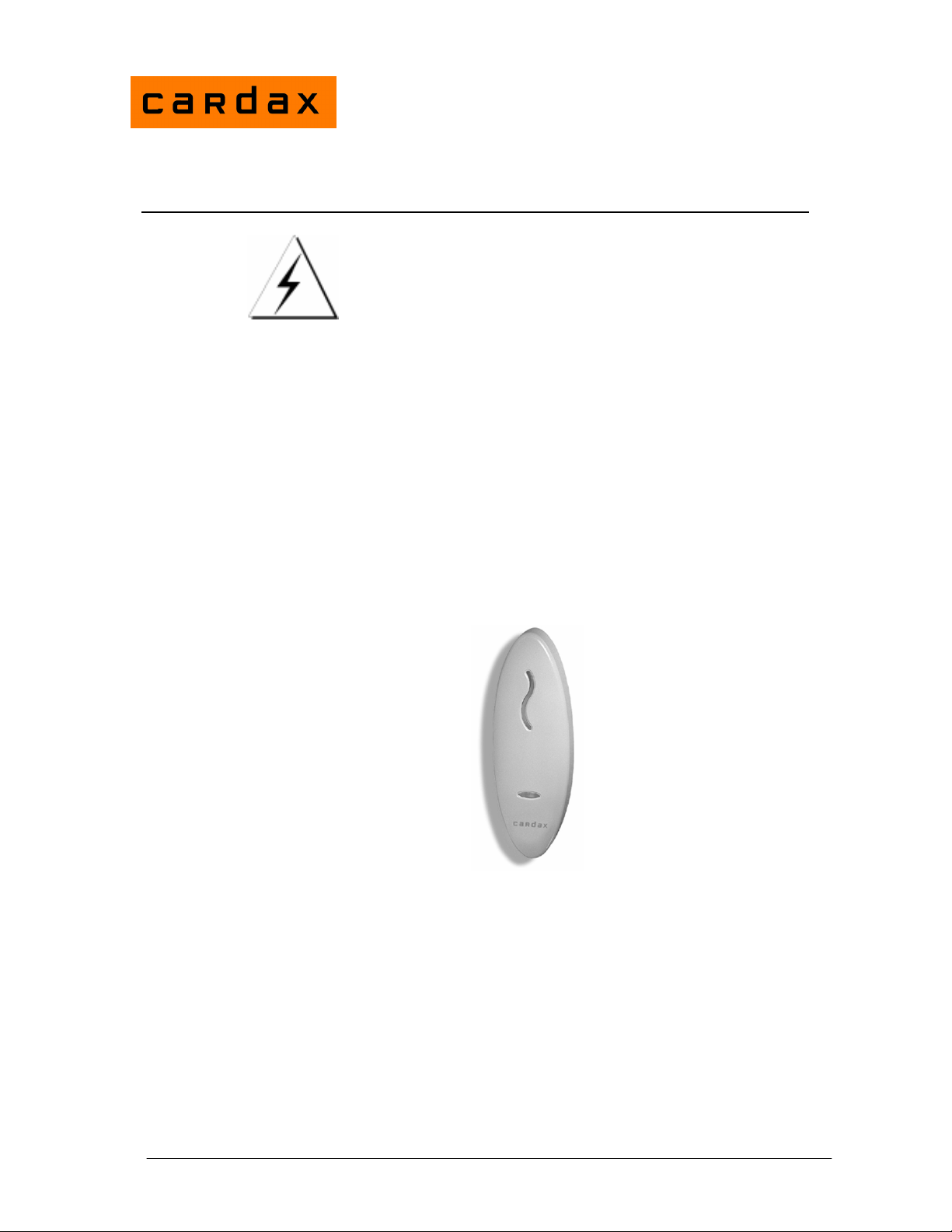
Prox Mifare Series (Teardrop)
Before you Begin
Unpack the Prox Mifare Series (Teardrop) reader and check the shipment
contains the following items:
• 1 x Prox Mifare Series (Teardrop) reader base
• 1 x Prox Mifare Series (Teardrop) reader facia
• 1 x printed circuit board (PCB) assembly
• 1 x cable assembly
• 1 x M3 Torx Post Security screw
• 4 x self tapper pozi counter sunk fixing screws (two different lengths)
WARNING: You must use the screws provided, as using other types of
screws could interfere with the electronics. (See the “Mounting” section
later for further explanation.)
Installation Note
CAUTION
This equipment contains components that can be damaged by
electrostatic discharge. Ensure both you and the equipment are
earthed before beginning any servicing.
Power Supply Requirements
Power for the Prox Mifare Series (Teardrop) reader is usually taken from the
incoming supply of the device to which it is connected. That is, from the:
• Cardax FT Reader I/O Interface
• Cardax FT Controller 3000
• Cardax FT Universal Reader Interface (Cardax FT URI)
• Cardax Commander Universal Reader Interface (Cardax Commander URI).
The supply at the reader should be 13.6 V DC ± 15%. The current draw is 180
mA per reader. This is in addition to the requirements of any other device (for
example, the URI) powered from the same supply.
Part number 3E1100 R12 1
June 2007
Page 2
Cabling
Prox Mifare Series (Teardrop) readers require a good quality linear power
source. If you do not use the recommended power supply, it may affect the
performance of the reader.
Note: Switch mode power supplies are not recommended as they may reduce
the read range of the Prox Mifare Series (Teardrop) reader.
The Prox Mifare Series (Teardrop) reader uses the Cardax IV communications
system. This means it can be connected to the following equipment:
• Cardax FT Reader I/O Interface
• Cardax FT Controller 3000
• Cardax FT URI
• Cardax Commander URI
2
Use 4 core, 0.2 mm
(AWG 24) cabling with a maximum, nominal capacitance
of 120 pf/m. The maximum external diameter of the cable must not exceed 5
mm (1/5 inch).
With this type of cable, the maximum distance between the Prox Mifare Series
(Teardrop) reader and the device to which it connects is 200 m (650 ft).
Note: You need a special cable terminating tool to connect the building cabling
to the Prox Mifare Series (Teardrop) reader. The tool has a head (Part
No. C861145) and handle (Part No. C861115). You also need a special
tool (Part No. C41611 ) to open the Prox Mifare Series (Teardrop)
reader if necessary.
Mounting Distance Between Proximity Readers
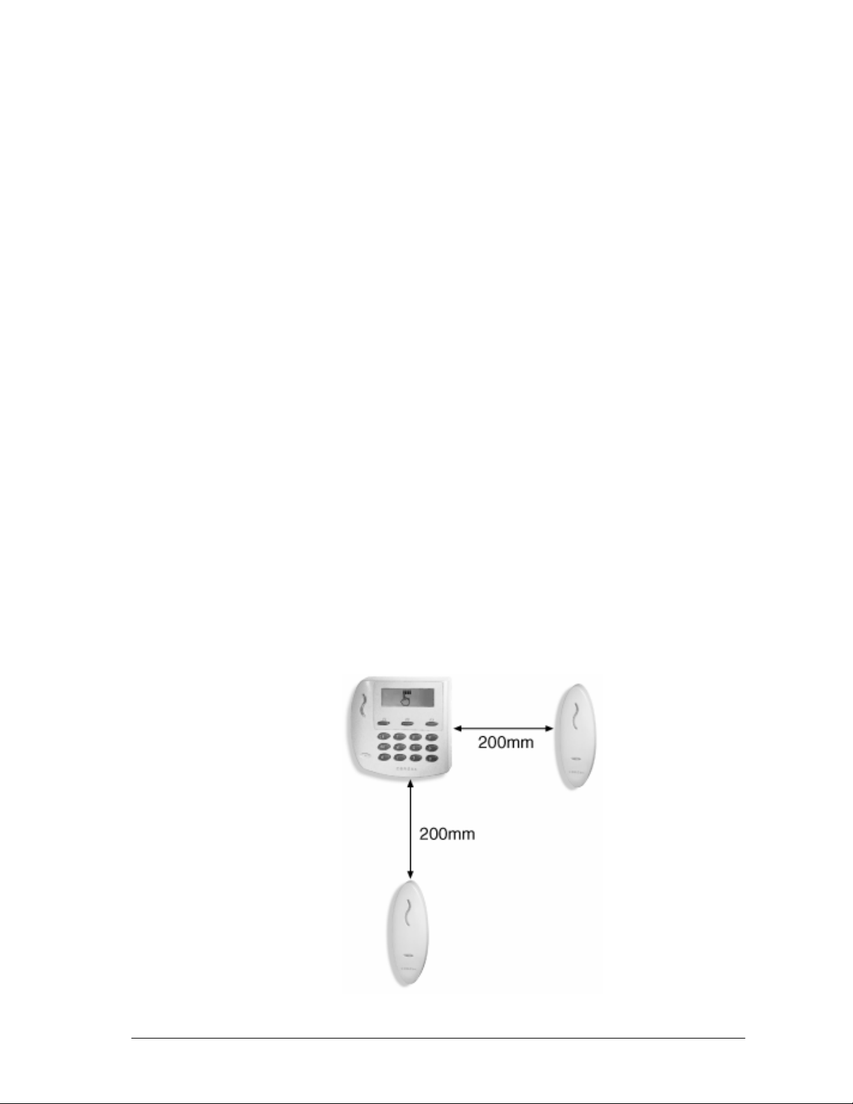
The distance between any 2 proximity readers must be greater than 200mm in
all directions.
2 Part number 3E1100 R12
June 2007
Page 3
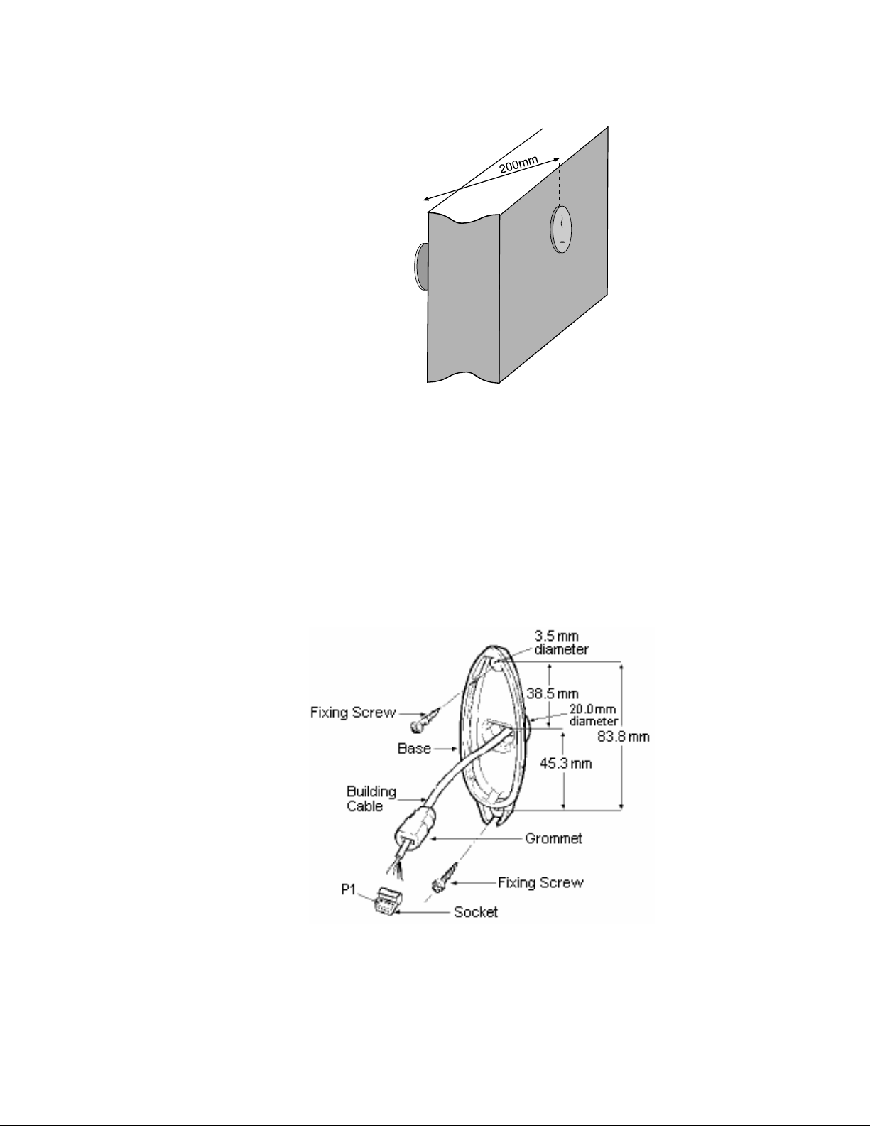
Please note that 200mm in all directions includes the distance through walls.
Mounting
Proximity
Reader
Proximity
Reader
Wall
Less than
200mm
thick
Note: The Prox Mifare Series (Teardrop) reader has been designed to metric
specifications. Therefore any imperial measurements provided are
approximate only.
The Prox Mifare Series (Teardrop) reader is designed to be mounted on any
solid flat surface. However installation on metal surfaces, particularly those
with a large surface area will reduce read range. The extent to which the range
is reduced will depend upon the type of metal used. To minimise this effect,
plastic spacers which may be mounted between the reader and the metal
surface are available (Part number C190980). Please contact your local Cardax
dealer for more information.
Note: The grommet through which the cables feed into the base of the Prox
Mifare Series (Teardrop) reader helps to keep the unit waterproof.
Using the mounting dimensions on the back of this Installation Note as a guide,
drill a 20 mm (
Part number 3E1100 R12 3
June 2007
3
/4 inch) diameter hole for the base extrusion through or into the
Page 4
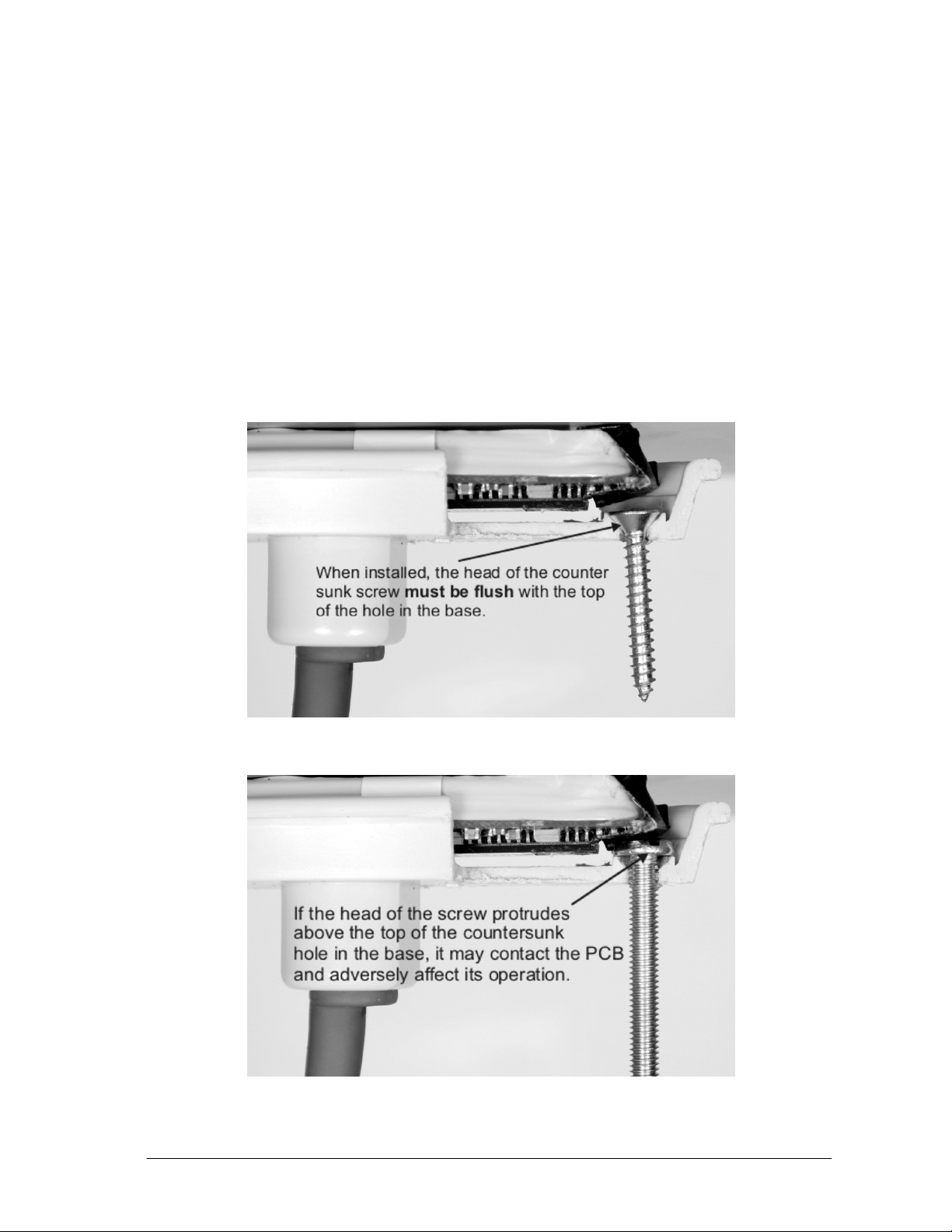
mounting surface to a minimum depth of 40 mm (11/2 in).
Drill two pilot holes for the fixing screws.
Run the building cabling through the base and grommet.
3
Fit the base to the 20 mm (
/4 inch) hole and secure it to the mounting surface
using two of the fixing screws provided.
Note: The surface the reader is being attached to will determine which length
screws are most appropriate from those provided.
WARNING: You must use the screws provided, taking care not to overtighten them. Make sure that the heads of the counter sunk screws are flush
with the top of the holes in the base, and ensure there is clearance for the screw
that closes the base and facia together.
Failure to do this, and/or using other types of screws could interfere with the
electronics.
Please note that the manufacturers warranty is voided if the electronics are
damaged as a result of the incorrect screws being used or installed incorrectly
4 Part number 3E1100 R12
June 2007
Page 5
to secure the base.
Push the socket back into the grommet.
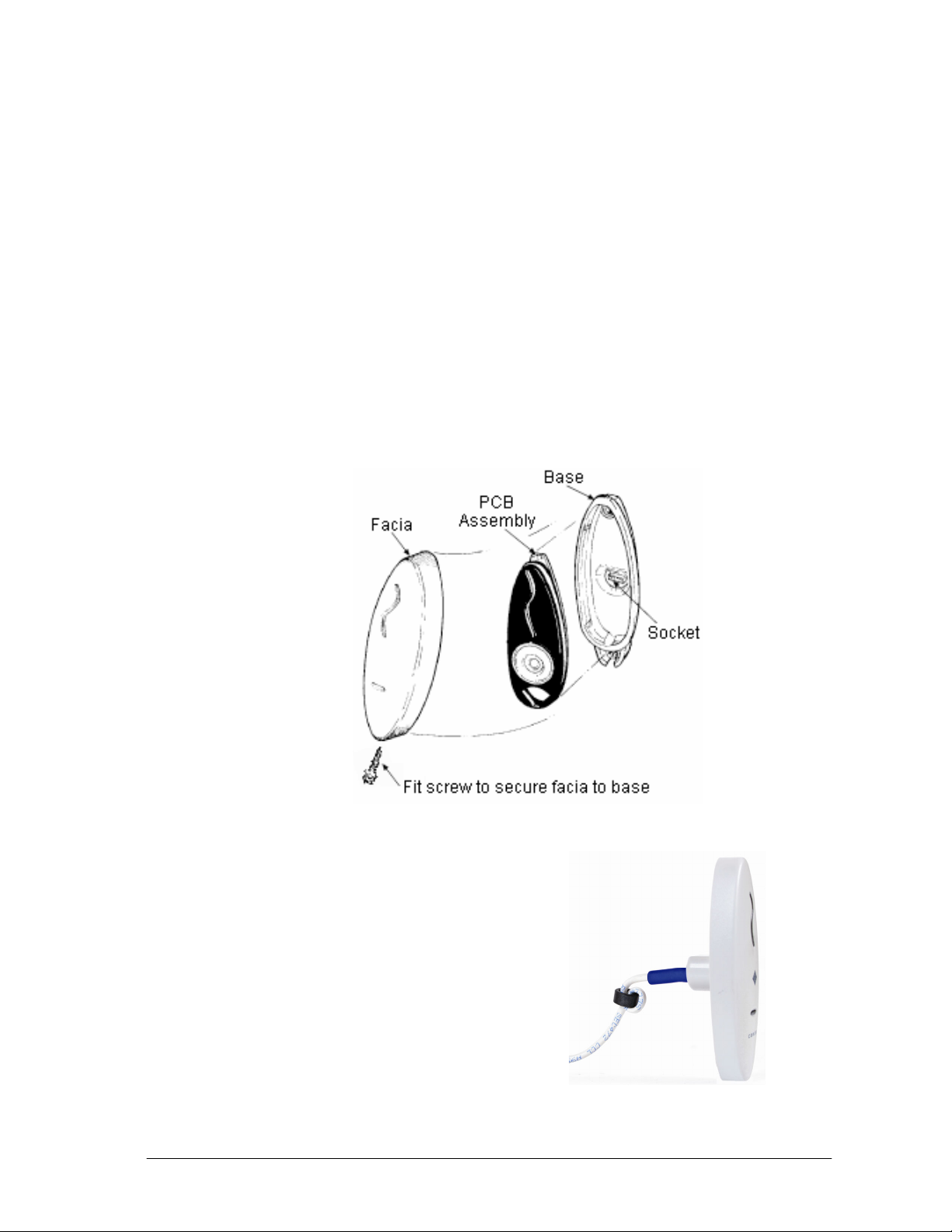
Push the grommet and socket back into the Prox Mifare Series (Teardrop)
reader base.
Check the tape covering the antenna wire solder joints is in position. Install the
PCB assembly into the base, ensuring the connector on the back of the PCB
assembly fits into the socket in the base. The PCB assembly should click into
place.
Fit the facia onto the base by clipping the small lip, inside the facia, over the
top edge of the base and holding the top, press the bottom of the facia down
over the base. Then insert the M3 x 16 Torx Security Screw (using an M3
Torx Post Security screwdriver) through the hole at the bottom of the facia and
into the threaded metal insert in the base to secure the facia.
Removal of the facia is a simple reversal of these steps.
FCC Compliance
For markets requiring FCC compliance, a
ferrite (part number C190977) must be
applied to the cable, with two-turns of the
cable running through it. Position the
ferrite as close to the entry point of the
reader as possible, as shown:
Part number 3E1100 R12 5
June 2007
Page 6
Connections
The Prox Mifare Series (Teardrop) reader connects to one of the following:
• Cardax FT Controller 3000
• Cardax FT Reader I/O Interface
• Cardax FT URI
• Cardax Commander URI
Use the cable terminating tool to connect the cables to the socket as described
in the following sections.
Pin number 4 of the Prox Mifare Series (Teardrop) reader connector feeds into
the cable terminating tool first.
Connecting to the Cardax FT Controller 3000
The Cardax FT Controller 3000 interfaces the following types of reader into
the Cardax FT Command Centre system:
• Cardax IV readers, including Prox Mifare Series (Teardrop) readers
• Wiegand readers
Each Cardax FT Controller 3000 can interface up to eight Prox Mifare Series
(Teardrop) readers into the Cardax FT Command Centre system.
The ports to which the Prox Mifare Series (Teardrop) reader can connect are
set up as four distinct groups (numbered 1 to 4). Each group provides
connection for two Prox Mifare Series (Teardrop) readers or other Cardax IV
readers. Refer to the following diagram for the location of the ports on the
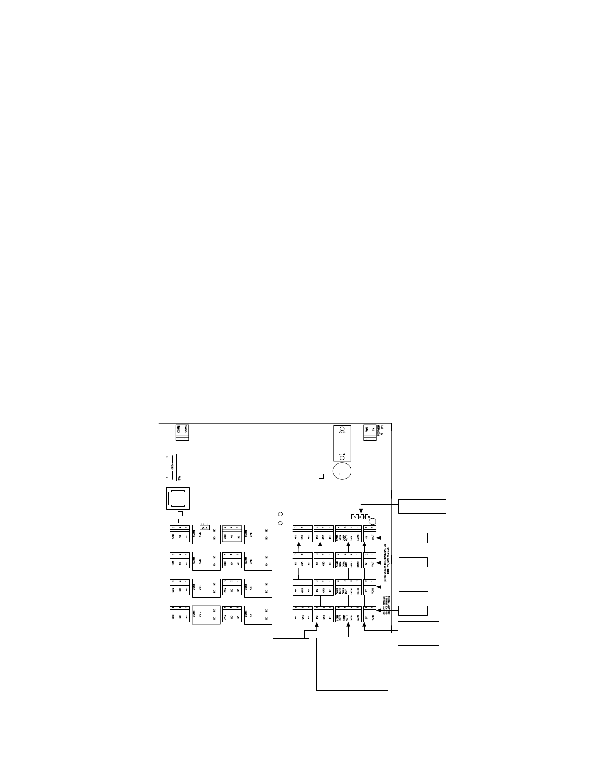
Cardax FT Controller 3000.
P4
RS485
PF4
PF3
PF2
PF1 PE1
P4
P2
DETECTOR
LED
PE4
PE3
PE2
PC1 to PC4
Inputs
pin 1 = Input 1
pin 2 = Ground
pin 3 = Input 2
PD4
PD3
PD3
PD2
PD2
PD1
PD1
P3
PC4
PC4PD4
PC3
PC3
PC2
PC2
PC1
PC1
PB1 to PB4
2 x Cardax IV Readers
per connector
Reader 1 = pins 1 & 3
Reader 2 = pins 2 & 4
Pin 1 = Reader 1 t ransmit
Pin 2 = Reader 2 t ransmit
Pin 3 = Reader 1 receive
Pin 4 = Reader 2 receive
P1
RS485
J1 to J4
terminating resistors
PA4
PB4
PA4
POWER
OUT
PA3
PB3
PA3
POWER
OUT
PA2
PB2
PA2
POWER
OUT
PA1
PB1
PA1
POWER
OUT
Group 4
Group 3
Group 2
Group 1
PA1 to PA 4
Power Out
pin 1 = power out
pin 2 = 0 V
6 Part number 3E1100 R12
June 2007
Page 7
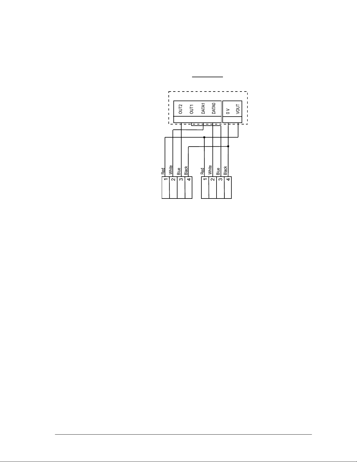
Make the connections from the Prox Mifare Series (Teardrop) reader to the
Cardax FT Controller 3000 as shown:
Controller 3000
Group (x4)
PB1 and PA1... to... PB4 and PA4
4 3 2 1
Prox Plus Mifare
Reader 2
PB
Prox Plus Mifare
Reader 1
PA
2 1
Note:
Within each group, you cannot mix Cardax IV readers with Wiegand Readers.
This is because connecting one Wiegand reader requires all four pins on plug
PB. For example, if you connect a Prox Mifare Series (Teardrop) reader to Port
1 of Group 1, Port 2 of Group 1 can only connect to another Cardax IV reader.
The terminating resistors (J1 for Group 1, J2 for Group 2, etc.) must NOT be
fitted for those groups to which Prox Mifare Series (Teardrop) readers are
connected.
Part number 3E1100 R12 7
June 2007
Page 8
Connecting to the Cardax FT Reader I/O Interface
The Cardax FT Reader I/O Interface has connections for up to sixteen Prox
Mifare Series (Teardrop) readers or other Cardax IV readers.
The Prox Mifare Series (Teardrop) reader connects to either plug PA or PB in
Groups 1 to 8.
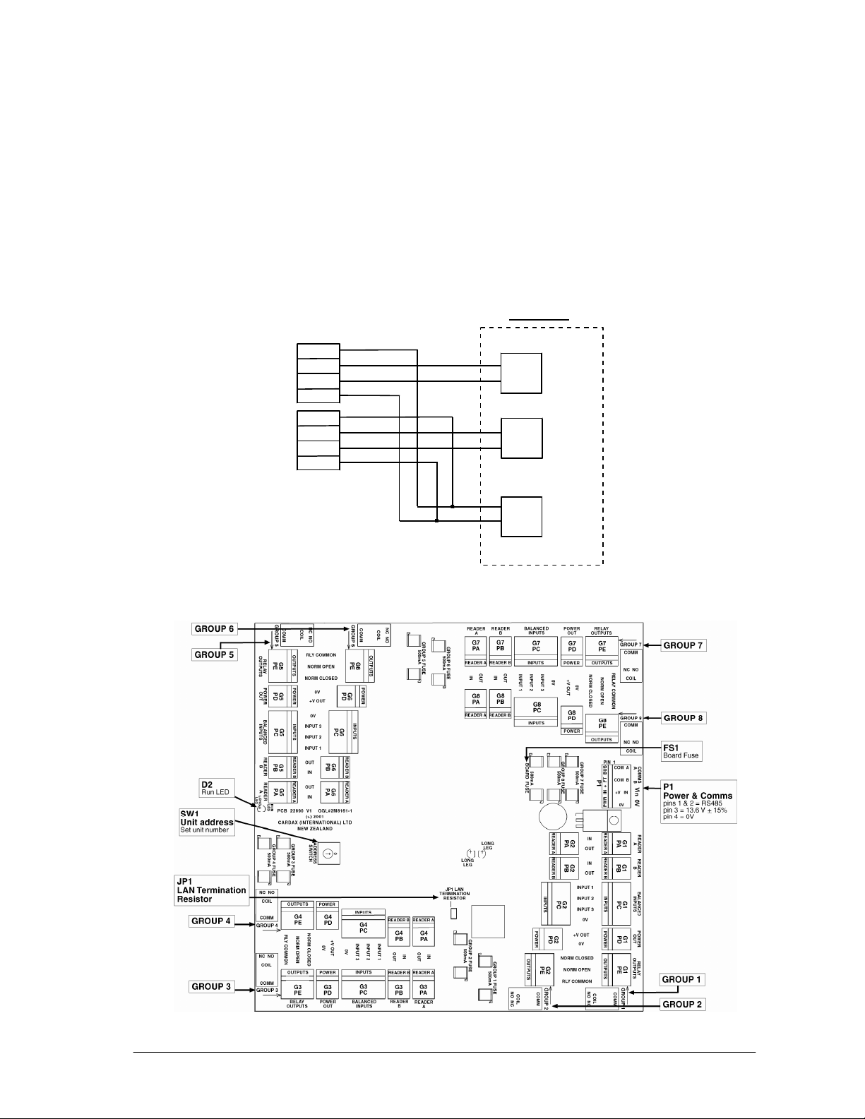
Make the connections from the Prox Mifare Series (Teardrop) reader to the
Reader I/O interface as shown:
Reader I/O Interface
Prox Plus Mifare Readers
Red
1
White
2
Blue
3
Black
4
Red
1
White
2
Blue
3
Black
4
Group (x8)
IN
OUT
IN
OUT
+V
0
Reader A
(PA)
Reader B
(PB)
Power
(PD)
For the location of the plugs on the Reader I/O Interface, refer to the
component layout diagram:
8 Part number 3E1100 R12
June 2007
Page 9
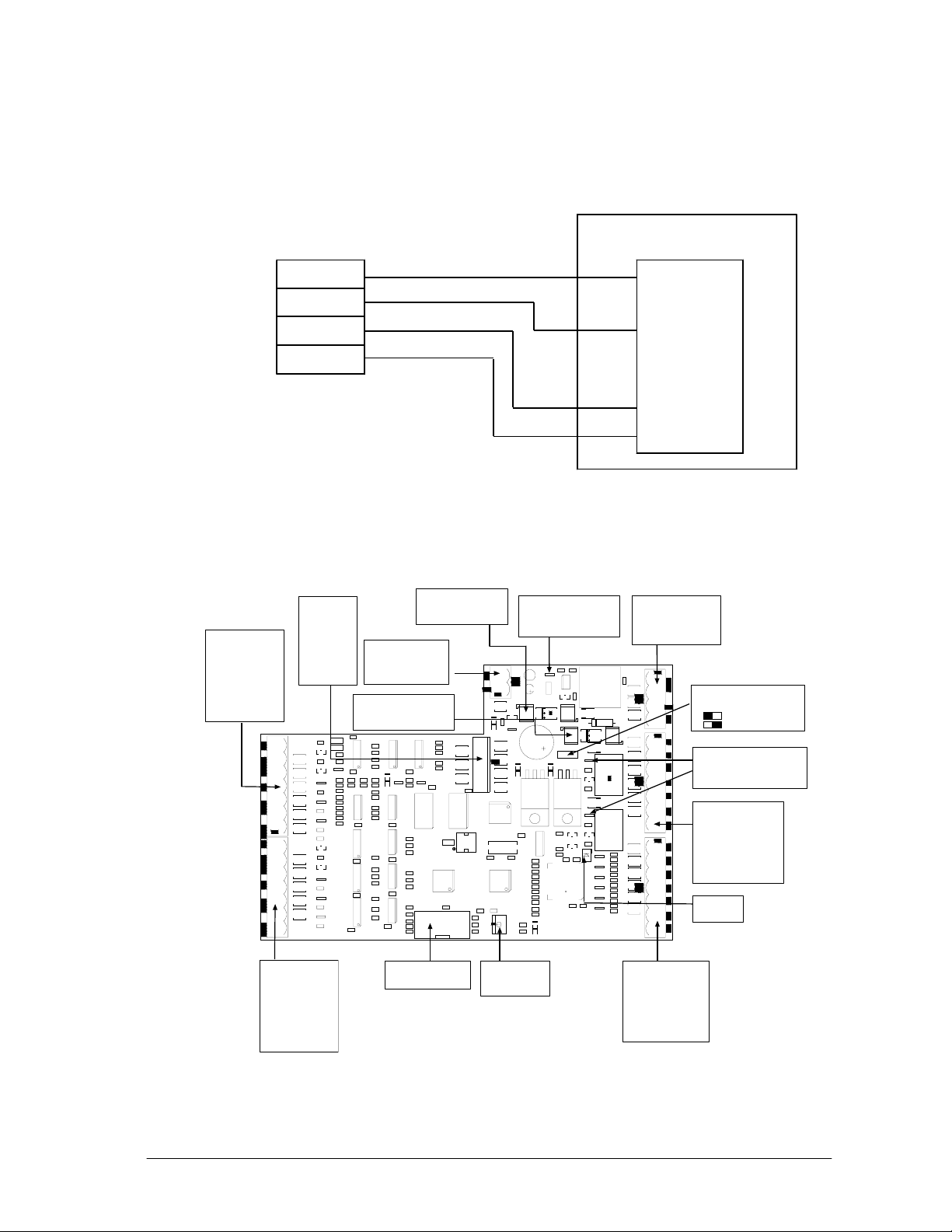
Connecting to the Cardax FT URI
Connect the cables to the socket as shown.
Cardax FT Universal Reader Interface
Prox Plus Mifare Connector
Black
4
Blue
3
White
2
Red
1
Plug P1 or P2
GND
OUTPUTS
OUTPUTS
DET
COMMS
COMMS
5/12V
Connect the Prox Mifare Series (Teardrop) reader connector to either the P1 or
P2 plug on the Cardax FT URI. Refer to the Cardax FT URI component layout
diagram, next, for the location of the plugs.
P2
Non-CardaxFT
Reader 2
pin 1 = 5/12 V power
pin 2 = DataA
pin 3 = DataB
pin 4 = Card detect
pin 5 = LED output
pin 6 = Beeper output
pin 7 = Ground
P3
Keypad
pin 1 = Row1
pin 2 = Row 2
pin 3 = Row 3
pin 4 = Row 4
pin 5 = Column1
pin 6 = Column2
pin 7 = Column3
pin 8 = Ground
P2
D19
D6
D5
R7
D4
Q2
D3
D2
D1
P1
(c)1999 PEC(New Zeala nd) Ltd
F1
13.6 V Input Fuse
Rating = 500mA
P6
13.6 V ± 15%out
pin 1 = 13.6 V ± 15%
pin 2 = Ground 3A fused
F2
13.6 V Output Fuse
Rating = 3A
JP2
D20
D15
P8
210
1
9
22825V2 Assy 22826
D10
Comms LED
flashing = communicating with
D10
E
D22
D11
SW1
FT Controller
U19
5V
JP1
12V
D21
D13
T1
D16
D17
NC NO
COIL
Q7
COMM
D14
NC NO
COIL
RLY2
COMM
D18
D23
D24
D25
D26
D27
D28
REV[A][B][C]
D12
P5
Power & Comms
pins 1 & 2 = RS485
pin 3 = 13.6 V ± 15%
pin 4 = 0V
Q41
Q26
R53
R50
Q27
R54
R51
Q28
R55
R52
Q29
R79
R94
R80
Q30
R95
R81
Q31
R96
JP1
Reader Voltage select
D17 and D21
Relay state indicators
LED on = Energised
LED off = De-energised
P7
Relay Outputs
pin 1 = R1 Normally closed
pin 2 = R1 Normally open
pin 3 = R1 Common
pin 4 = R2 Normally closed
pin 5 = R2 Normally open
pin 6 = R2 Common
pin 7 = Ground
D18
Run LED
= 5V (200mA total)
= 12V (1A total)
P1
Non-CardaxFT
Reader 1
pin 1 = 5/12 V power
pin 2 = DataA
pin 3 = DataB
pin 4 = Card detect
pin 5 = LED output
pin 6 = Beeper output
pin 7 = Ground
Part number 3E1100 R12 9
P8
Diagnostic port
SW1
Unit address
Set unit number
P4
Balanced Inputs
pin 1 = Input1
pin 2 = Input 2
pin 3 = Input 3
pin 4 = Input 4
pin 5 = Input 5
pin 6 = Input 6
pin 7 = Ground
June 2007
Page 10
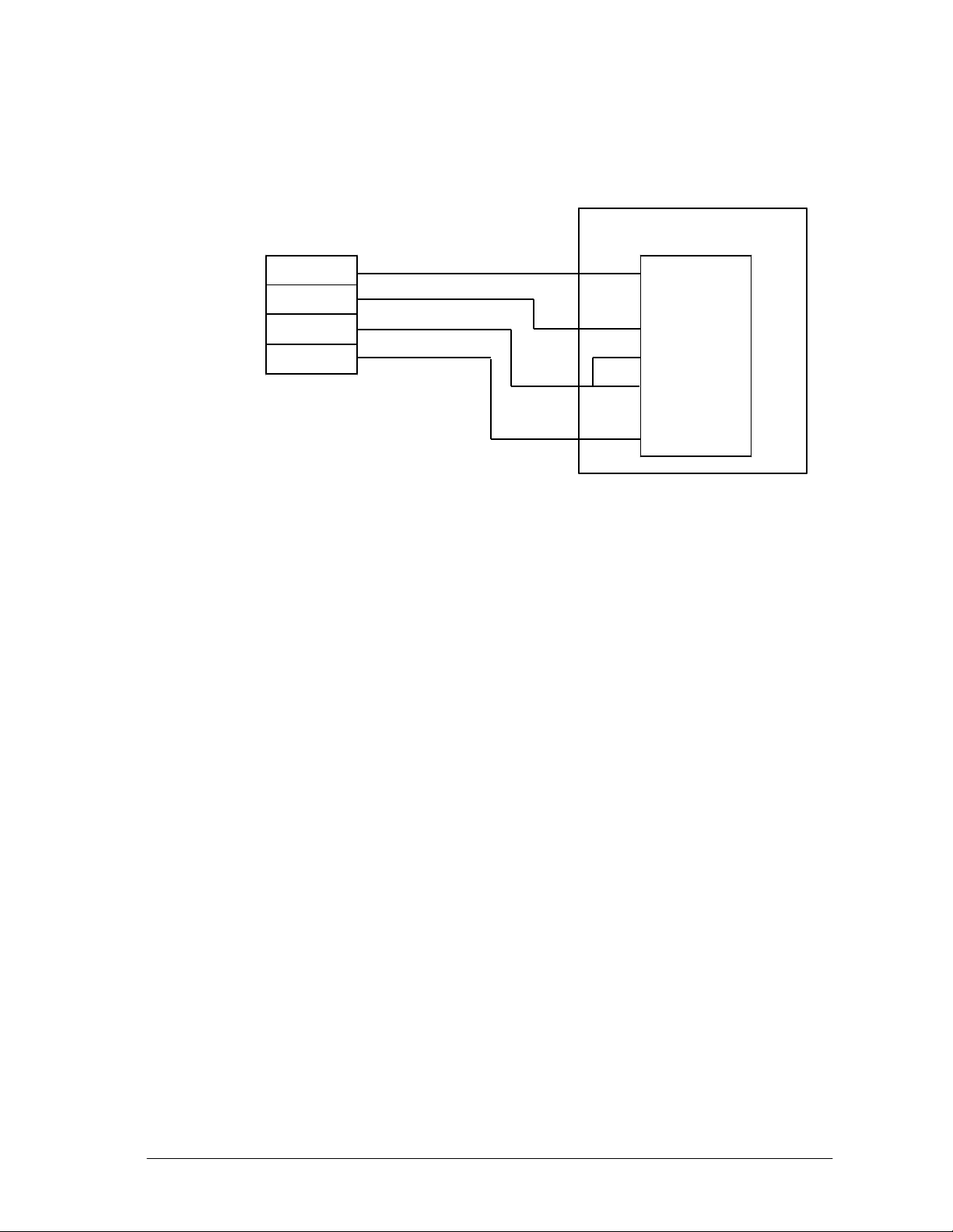
Connecting to the Cardax Commander URI
Connect the cables to the socket as shown in the following diagram.
Universal Reader Interface
Prox Plus Mifare Connector
Black
4
Blue
3
White
2
Red
1
Plug P4 (Exit) or P5 (Entry)
GND
1
BPR
2
LED
3
DET
4
1-CK
5
0-DT
6
5/12V
7
Note:
Refer to Cardax Commander URI Components, for the location of the Cardax
Commander URI components.
10 Part number 3E1100 R12
June 2007
Page 11

Initialisation
Initialising with the Cardax FT Controller 3000
Refer to the Cardax FT Controller 3000 Installation Note (Part number
3E1089) for initialisation instructions.
Initialisation of the Cardax FT Controller 3000 does not require prior
connection to the Prox Mifare Series (Teardrop) reader. The Prox Mifare Series
(Teardrop) reader will be operational as soon as it is:
• connected to a Cardax FT Controller 3000, and
• configured as a Cardax IV reader within the Cardax FT Command Centre
system.
Initialising with the Cardax FT Reader I/O Interface
Refer to the Cardax FT Reader I/O Interface Installation Note (Gallagher Part
number 3E1016) for initialisation instructions.
Initialisation of the Cardax FT Reader I/O Interface does not require prior
connection to the Prox Mifare Series (Teardrop) reader. The Prox Mifare Series
(Teardrop) reader will be operational as soon as it is:
• connected to a Cardax FT Reader I/O Interface, and
• configured as a Cardax IV reader within the Cardax FT Command Centre
system.
Initialising with the Cardax FT URI
Refer to the Cardax FT Universal Reader Interface Installation Note
(Gallagher Part number 3C4518) for initialisation instructions.
Initialisation of the Cardax FT URI does not require prior connection to the
Prox Mifare Series (Teardrop) reader. The Prox Mifare Series (Teardrop)
reader will be operational as soon as it is:
• connected to a Cardax FT URI, and
• configured as a Cardax IV reader within the Cardax FT Command Centre
system.
Initialising with the Cardax Commander URI
Type of Door Lock
Depending on the type of lock fitted to the door that the reader is controlling,
you will need to initialise the URI with the door either closed or open.
If you initialise the URI with the door held open, it sets the door to unlock and
remains unlocked until the door is fully closed again. If you initialise the URI
with the door closed it sets the door to unlock and resets to lock as soon as the
door is opened.
Part number 3E1100 R12 11
June 2007
Page 12

Note:
If you are installing the Prox Mifare Series (Teardrop) reader to control a
turnstile you should consult the turnstile manufacturer for details of the locking
mechanism used.
Push-Button Exit
If the door has a push button exit, ensure the URI Exit terminal has the pushbutton fitted and correctly terminated with a 10 k
resistor before you power
on.
Check Software Version
You should check the URI software version to ensure it is correct for your
installation. The software version number is written on the label of the EPROM
mounted at the bottom right of the URI processor board.
URI software versions that are compatible with the Prox Mifare Series
(Teardrop) reader are shown below:
Software Reader Type
vW3.61 to vW3.67 or vW6.xx
One door Cardax Prox or Swipe Readers
series *
vW7.xx TC series URI Special Options
vW4.74 to vW4.81 or vW9.xx
Two door Cardax Prox or Swipe Readers
series *
Note: * These software versions will have one of the following suffixes:
GT = 2 wire modem connection
G = 4 wire modem connection
// = direct connection via comms lines ie. no modem
12 Part number 3E1100 R12
June 2007
Page 13
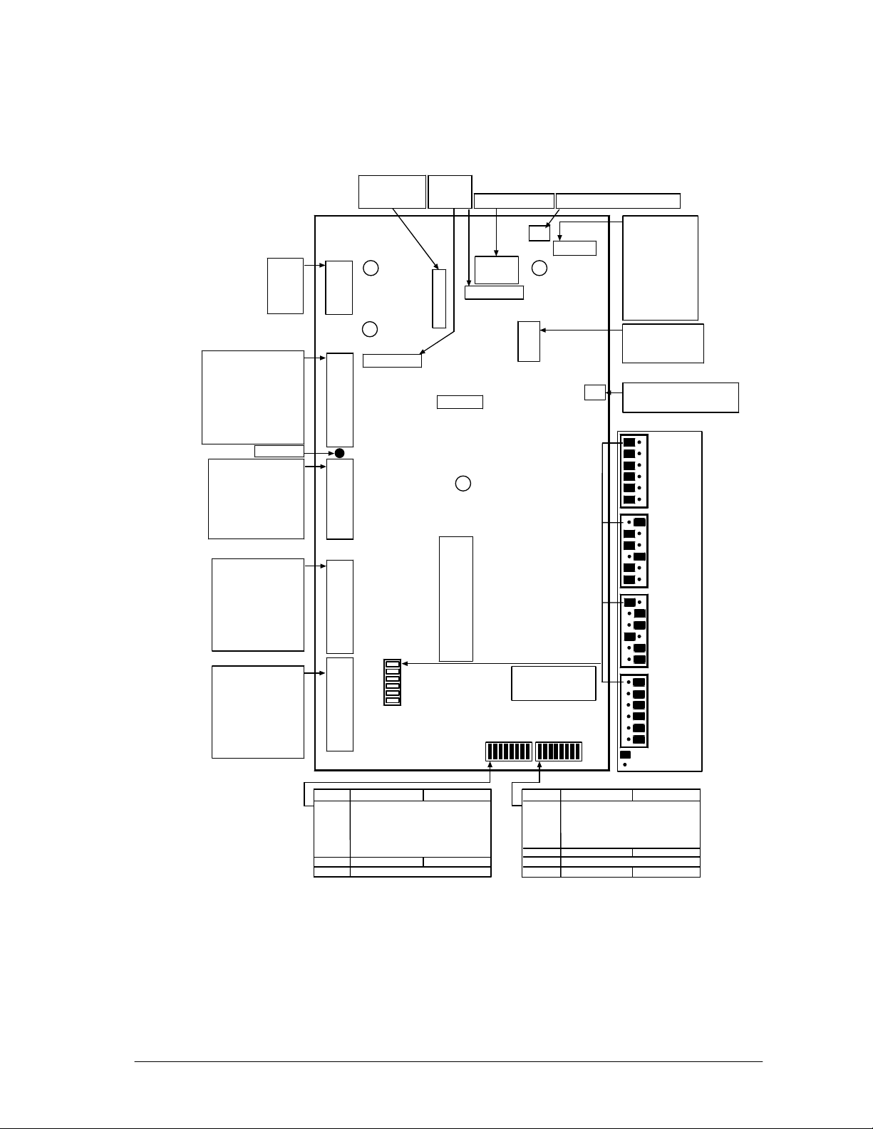
Cardax Commander URI Components
Please refer to the diagram below for the location of the Cardax Commander
URI components.
Ground
Normally Open
Relay Common
Normally Closed
Door Unlock
Door Open
Push-Button Exit
Input 3/*Unlock
* Applies to 2-Door
URI only
Earth Wire
Ground
Input 1
Input 2
Input 4/*Open
Input 5/*Exit
Ground
Beeper
LED
Card Detect
Clock/Data 1
Data/Data 0
5 or 12 V Out
Ground
COM B
COM A
Power
GND
N.O.
COM
N.C.
UNLK
OPEN
EXIT
GND
AUX1
AUX2
AUX3
AUX4
AUX5
GND
BPR
LED
DET
1-CK
0-DT
5/12V
Comms
& Power
P1
P2
P3
P4
Fuse
(Reader Power
Supply)
D8
Comms In
D10
Comms Out
Door 1 Inputs
&
Output Relay
Auxiliary
and/or
Door 2 Inputs
Door 1 Exit
Reader OR
Door 2 Entry
Reader
Fuses
(Relay
Contacts)
F1
F3
Tamper
PLD
Lithium Battery
F2
Aux. Relay
D44
Diagnostics/
Processing
J1
D45
5 V DC
P8
or Door 2
Relay
Lithium Battery Jumper
Top Ro w
1
Row 2
2
Row 3
J2
3
Bottom Row
4
Left Column
5
Middle Column
6
Right Column
7
Not Used
8
Normally Open
1
Relay Common
2
Normally Closed
3
OFF
ON
Cardax III
5 V
Cardax
Prox (125,
Mifare or
TIRIS)/
Cardax
Swipe
12 V
Wiegand
5 V
P7
Door 1
Keypad
Confirmed Entry
No Confirmed Entry
LED
GND
BPR
LED
DET
1-CK
0-DT
5/12V
P5
Jumpers
Door 1 Entry
Reader
Switch On Off
11
22
3 4 Unit
4 8 Address
516
632
7 Initialise Normal
8* *see note below
* Depends on Software Version.
DSW1
ON
OFF
EPROM
DSW2
Switch On Off
1
2 Card Format
3
4
5
6* Validated Exit* Normal*
7* *see note below
8KeypadNo Keypad
ON
OFF
Wiegand
12 V
Jumper Connected
No Jumper
Ground
Beeper
Card Detect
Clock/Data 1
Data/Data 0
5 or 12 V Out
Part number 3E1100 R12 13
June 2007
Page 14
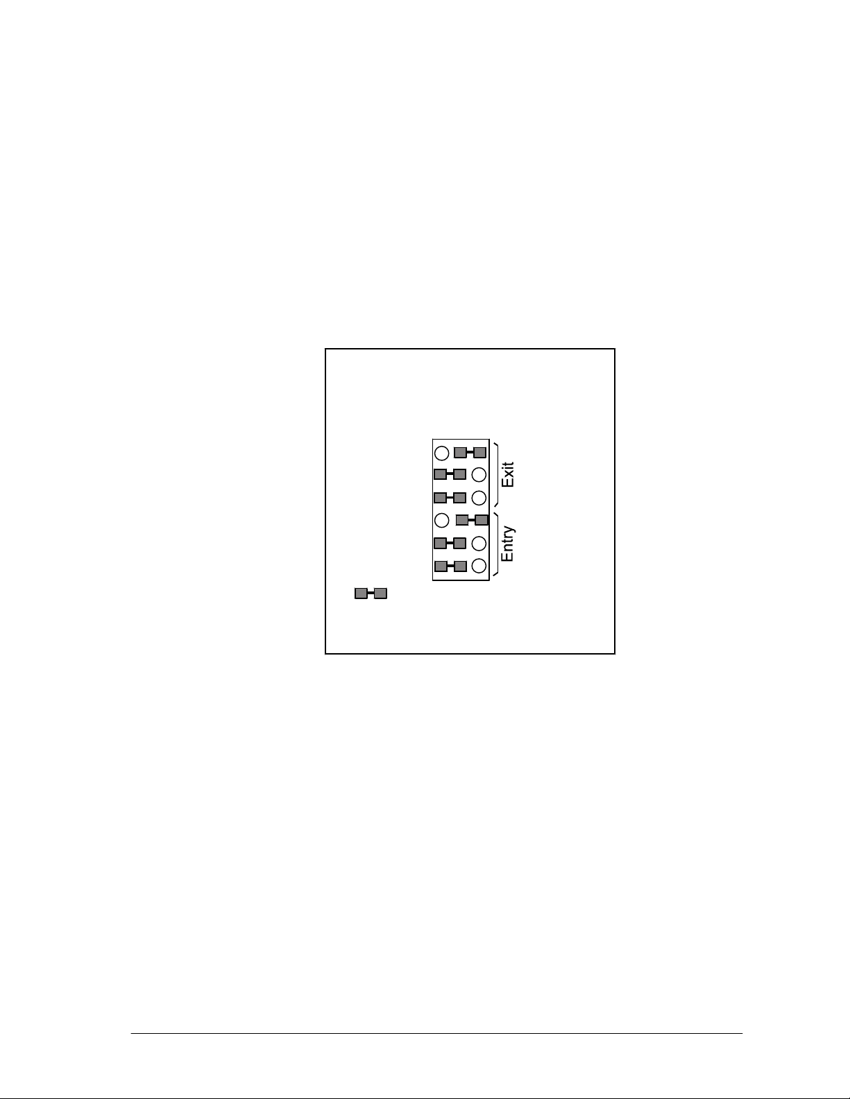
Setting the Jumpers
Tamper the URI by opening the door of the cabinet. This releases the tamper
switch.
The URI has a set of six jumpers grouped into two sets of three. One group is
labelled ENTRY and the other is labelled EXIT.
ENTRY jumpers set the voltage and card type of the reader connected to plug
P5. EXIT jumpers set the voltage and card type of the reader connected to plug
P4.
Set the Entry and Exit jumpers for the Prox Mifare Series (Teardrop) reader as
shown below:
Entry and Exit Jumper Settings
Cardax
12 V
1
2
3
4
5
6
= jumper in place
Pins 3 and 6 = voltage supplied to reader
Pins 1,2 4 and 5 = reader type
Confirmed Entry
Connector J2 on the URI controls the Confirmed Entry function. If you
initialise the URI with no jumper fitted on J2 the Confirmed Entry function
will be ON. To switch the Confirmed Entry function OFF, you must initialise
the URI with a mini-jumper fitted across both pins of connector J2.
Connecting the Reader
Connect the Prox Mifare Series (Teardrop) reader to the URI Entry Plug P5.
Note:
If you are using two entry readers (2 door software) you must connect the
second entry reader to URI Plug P4 to initialise the URI. Ensure Entry and Exit
jumpers are set to the same configuration.
If you are only using an Exit reader you must connect the reader to the Entry
Plug P5 to initialise the URI. After you have initialised the URI you should
connect the Exit reader to URI Exit Plug P4.
14 Part number 3E1100 R12
June 2007
Page 15

Setting the Dip Switches
Set DIPSW1 as follows:
Switches On Off
1
2
3
4
5
6
7
8
1
2
Unit
4
Addresses
8
16
32
Initialise
1 door software
= liftcar reader
2 door software
= keypad on door 2
Normal
1 door software
= door reader
2 door software
= no keypad on door 2
Set DIPSW2 as follows, where 0 = OFF and 1 = ON:
URI Software
vW6.xx
and
vW9.xx
Reader
Prox Mifare Series (Teardrop) reader
DIPSW2
12345678
00000000 00011000
only, no authorised exit
vW3.61 to vW3.67
and
vW4.74 to vW4.81
DIPSW2
12345678
Prox Mifare Series (Teardrop) reader
00000100 00011100
only, with authorised exit
Prox Mifare Series (Teardrop) reader
00000011 10011011
with external keypad and no
authorised exit.
Prox Mifare Series (Teardrop) reader
00000111 10011111
with external keypad and authorised
exit.
For further details on software versions refer to Check Software Version
earlier in this Installation Note.
Part number 3E1100 R12 15
June 2007
Page 16

Initialise Process
CAUTION
Do not fit the lithium battery jumper (J1) before powering
up the URI. If the jumper is fitted you must remove it and
!
Power up the URI.
The yellow LED (D45) should be permanently ON. This indicates that 5 V is
present on the board.
The green LED (D44) should flash twice, pause, then flash twice again. This is
a continuous sequence while the URI is unitialised and indicates it is
processing.
The red LED (D8) should flash if polls are received from the Commander.
Note:
A URI can be initialised without being connected to a Commander.
Set DIPSW1:7 to ON.
wait 10 seconds.
Present a Smart Card to the Prox Mifare Series (Teardrop) reader.
Note:
You must present the card within 30 seconds of setting DIPSW1:7 to ON. If
you are initialising with two readers connected to the URI, you should present
the card to the reader on URI plug P5.
Set DIPSW1:7 to OFF
The green LED (D44) will begin flashing continuously.
The other red LED (D10) will flash each time the URI replies to a poll from the
Commander.
Replace the lithium battery jumper J1.
Restore the tamper by closing the door of the URI cabinet.
16 Part number 3E1100 R12
June 2007
Page 17

Technical specification
Note: All specifications are subject to appropriate installation.
Routine maintenance and serviceable parts:
Not applicable for a Cardax Prox Mifare Series (Teardrop) reader
Cleaning:
The Cardax Prox Mifare Series (Teardrop) reader should only be cleaned
with clean, lint free, damp cloth
Power required:
Voltage 13.6 ± 15% V DC
Current < = 180mA
Environmental:
Operating temperature -100C to +500C
Humidity 95% non-condensing
Environmental Protection IP54
Note: Direct sunlight may increase the internal reader temperature above
the ambient temperature level.
Mounting Height:
1100mm (3 ft) to centre
Approvals and Standards
This equipment has been tested and found to comply with the limits for a Class
B digital device, pursuant to Part 15 of the FCC Rules. These limits are
designed to provide reasonable protection against harmful interference in a
residential installation. This equipment generates, uses and can radiate radio
frequency energy and, if not installed and used in accordance with the
instructions, may cause harmful interference to radio communications.
However, there is no guarantee that interference will not occur in a particular
installation.
If this equipment does cause harmful interference to radio or television
reception, which can be determined by turning the equipment off and on, the
user is encouraged to try to correct the interference by one or more of the
following measures:
• Reorient or relocate the receiving antenna.
• Increase the separation between the equipment and receiver.
• Connect the equipment into an outlet on a circuit different from that to
which the receiver is connected.
• Consult the dealer or an experienced radio/TV technician for help.
Note: Changes or modifications not expressly approved by Gallagher Group
Limited could void the user's authority to operate the equipment.
ACN: 002132943
Part number 3E1100 R12 17
June 2007
Page 18
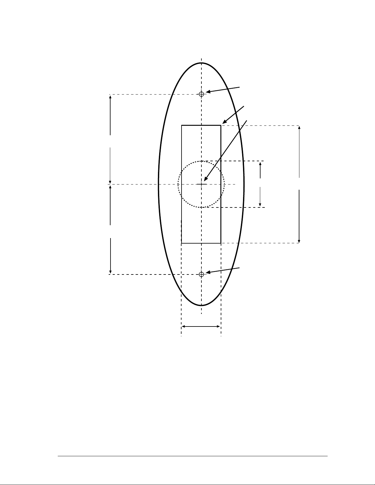
Mounting Dimensions
39 mm
Pilot hole
Slot
20 mm hole
45 mm
17 mm
20 mm
Pilot hole
51 mm
18 Part number 3E1100 R12
June 2007
 Loading...