

Page 1

InHome
™
Wireless
Motion
Sensor
Installation
Guide
Wires Not Included
™
Supported Models
This documentation applies to the following Card Access products:
WMS10
WMS10-EXT
Application Notes and Accessories
New accessories and application notes are constantly developed for the
InHome Wireless Motion Sensor ,so please see our web site for the latest in
application notes and accessories by going to www.cardaccess-inc.com/inhome
Important Safety Instructions
WARNING! Y ou should install this de vice in accordance with all national
and local electrical codes.
IMPORTANT! Improper use or installation of this device can result in
LOSS OF/DAMAGE TO PROPERTY.
IMPORTANT! You must operate this device in accordance with the
instructions and specifications in this Card Access InHome™Wireless
Motion Sensor Installation Guide.
IMPORTANT! Using this product in any manner other than outlined
in this document voids your warranty . Also,Card Access is NOT
responsible or otherwise liable in any way for an y damage resulting
from the misuse of this product. See the section of this document
entitled WARRANTY for details.
Features
The Card Access InHome™Wireless
Motion Sensor works with your
Control4®system and combines the
features of a passive infrared (PIR)
motion sensor with ambient light sensing detection into a single device. The
product allows wireless generation of
Control4 home automation events
based on room or area occupancy . It
integrates into Control4’s home
automation system as a standard
Motion Sensor Proxy with additional
programming variables for detected
light levels and day/night (dawn/dusk)
detection. LEDs provide indicators to
confirm you have successfully connected
the product to the Control4 system.
Additional LED feedback and diagnostics are available to test positioning of the
motion detector within a room (“walk test” mode).
With the InHome Wireless Motion Sensor you can extend home automation
control based on occupancy for locations inside or outside the home, without
the need to run control wires over long distances (or where you can’t run any
wires at all).
The InHome Wireless Motion Sensor enables home automation to adapt
based on whether a person is present, such as:
• Automated control of lights based on room occupancy
• Alerts when someone enters front walkway
• Detection of outdoor light levels for dawn/dusk events
• Automated pathway lighting
• And any other control application you can devise and safely integrate
Government policy and high energy costs are driving consumers toward more
environmentally-aware home power usage. The InHome Wireless Motion
Sensor ‘greens’ up the Control4-automated home by enabling occupancybased automation controls. Used in concert with additional Control4-enabled
products (wireless switches, relays, dimmers and thermostats),the motion
sensor can control HVAC,water heating and lighting systems to comply with
environmental policies, conserve resources, and save money on utilities.
The InHome Wireless Motion Sensor does this all without the wire. Or, as we
say: “Wires Not Included.”
What Is Included
You will find the following items inside the InHome Wireless Motion Sensor
package:
• Bubble bag containing one (1) InHome Wireless Motion Sensor
• Wall Mount Swivel Bracket
• Installation Guide / Product Warranty / Product Registration document
• Two (2) wall mounting screws
• Two (2) plastic dry wall anchors
• 9V alkaline battery
Specifications
The specifications for the Card Access InHome Wireless Motion/Light Sensor
are as follows:
Motion Detection Method: Passive Infrared
Coverage: 110°-160° Wide Angle Lens 10-50 ft (3m-15m)
depending on sensitivity setting, mounting
angle and temperature. Motion Sensors may
be cascaded together to improve coverage.
Recommended
Mounting Height: 7ft nominal (2.1m). Variable dependent upon
desired application
Indicator: Red LED to indicate motion upon initial power
up or after a programming change is sent from
Composer. Green LED for radio test.
Power Source: 9V alkaline (included) or lithium battery
Power Usage: ~17mA fully active
Estimated Battery Life: 1 to 2 years depending on usage (standard 9V
alkaline battery), lithium battery will provide
longer operation.
Device Temperature Range: Operational -20°F to 158°F (-28°C to 70°C)
Humidity 5% to 95% Non-Condensing
Storage -20°F to 158°F (-28°C to 70°C)
Internal Light Sensor
Measurement Range: ~0.1 lux to 10,000 lux
Dimensions (DxWxH): 1.8” x 2.5” x 3.4”
(47.6mm x 63.5mm x 85.7mm)
Rain Resistance: IP44 (Splash Proof) rated. The InHome
Wireless Motion Sensor is NOT waterproof and
must be kept out of direct contact with water.
The product must NOT be immersed.
Communications: Zigbee (IEEE 802.15.4) 2.4 GHz, 15-channel,
spread spectrum radio
1. Battery Installation
Install the 9V battery into the rear of the motion
sensor (see figure below). After the battery is
connected the motion sensor’s red LED (visible
through the motion sensor window) will blink for
approximately eight (8) seconds while a wireless connection is established with the Control4
system. The motion sensor requires a warm up
time of approximately 45 seconds before it can
reliably detect motion. After powering up the
unit, the walk test LED (red LED) is automatically
enabled for five (5) minutes, allowing the red
LED to indicate when motion is detected (See
“walk test and adjustment” below). This allows
the installer time to adjust the motion sensor
positioning and perform walk tests to verify that
motion detection is functioning as desired.
2. Add to Composer Project
To add the InHome Wireless Motion Sensor to your Composer project, select
the Search Tab, and choose ‘Motion Sensor’ in Device Type (see screenshot
below). The InHome Wireless Motion Sensor is identified to the Control4 system in the same manner as all other Control4 devices. When prompted to
identify the unit, depress the
button inside the InHome
Wireless Motion Sensor’s battery
compartment four (4) times. The
green LED will blink twice to confirm the ID has been sent to the
Control4 system and the MAC
address of the device will be
added to the appropriate field. T o
configure Composer Project
events based on the InHome
Wireless Motion Sensor’s states,
please refer to the Composer
documentation.
3. Operation
When motion is detected in the monitored area, the Wireless Motion Sensor
sends a ‘motion detected’ event to the Control4 system. When no motion
has been detected for the designated time period (‘Occupancy Hold Time‘) a
‘no motion’ event will be sent to the Control4 system. Using the slider on
the Properties Page in Composer,the Occupancy Hold Time may be adjusted
to values ranging from five (5) seconds to 60 minutes. Use the Occupancy
Hold Time for the length of time required for the duration of the event or for
the amount of time for a device to be controlled. For example, if you are controlling a light in a particular room, set the Occupancy Hold Time for amount
of time you want the light to stay ON after NO MORE MOVEMENT is detected.
Then use the ‘No Motion’ alert event to shut off the controlled light. The
higher the Occupancy Hold Time setting, the longer the battery life of the
InHome Wireless Motion Sensor.
4. Low Battery Indication
Battery Low and Battery Critical events are generated by the Control4 system
when the battery level on the Wireless Motion Sensor drops to a certain level.
These events can be used by Composer scripts to signal the installer and/or
the homeowner that battery replacement is needed.
5. Mounting
Select a mounting location for the InHome Wireless Motion Sensor. When
choosing an appropriate location the following should be considered:
• A mounting height of six (6) to eight (8) feet is recommended.
• Reliability of ZigBee mesh network coverage
• Shielding the motion sensor from direct sunlight, if possible, for better
motion sensing reliability
• Avoiding placement of the motion sensor near heat or cold producing devices
(e.g. air conditioning or furnace vents, fans, ovens,heaters, etc.) as this may
cause false triggers
The included wall mount swivel bracket is necessary to mount the Motion
Sensor at the desired location. Once a location is selected, attach the wall
mount swivel bracket to the location using the screws and wall anchors provided,
(see diagram 1). Once the wall mount swivel bracket is mounted to the wall,
slide the back of the sensor into the wall mount swivel bracket (see diagram
2). The mounting angle can be adjusted. Please refer to Section 3 “Walk Test
and Adjustment” to determine the best mounting angle.
TIP: If mounting the unit to drywall, you may need to mark and pre-drill
two (2) 3/16-inch-mounting holes at the two screw hole locations.
Press the plastic wall anchors (included) into the drilled holes.
NOTE: Make sure the InHome Wireless Motion Sensor is positioned for
good ZigBee wireless reception by (1) ensuring it is within 150 feet of
another ZigBee device and (2) avoiding other electrical equipment that
may cause interference with the ZigBee signal (such as 2.4Ghz cordless
telephones). If in doubt of ZigBee operation at the desired mounting
location, you can use a Card Access InHome Wireless Contact Switch
as a simple ZigBee functional tester to check for adequate operation.
6. Walk Test and Adjustment
It is important to perform a Walk T est,after mounting the
Wireless Motion Sensor ,in order to determine if the sensor
is properly detecting motion in the desired areas of the room
or location. The Walk Test mode will indicate whether motion
is detected by illuminating the red LED on the Wireless
Motion Sensor . The Walk Test mode will automatically be
activated for a 5-minute period after the unit is first powered up, or any time the
button in the Wireless Motion Sensor is pressed (see figure in section 2). Walk
T est is also activated via Composer when programming configuration changes
such as Sensitivity (made on the Properties page) are applied to the unit. The
unit will remain in Walk Test Mode for approximately 5 minutes after any of
these actions are executed and will exit the mode automatically .
Sensing motion and light inside and outside
the home gives you automation control that
responds to body heat and movement,or
changes in ambient light levels.
MOTION LIGHT OCCUPANCY CONTROL
Insert 9V alkaline battery
into the sensor.
The button is located inside
the battery compartment.
Diagram 2Diagram 1
Page 2
The angle of the Wireless Motion Sensor may be adjusted,in order to control
how far the Motion Sensor can “see”. T o reduce the detection range,simply tilt
the sensor downward. To increase the range, tilt the sensor upward. Range is
maximized when the sensor is tilted to 12 degrees. (It is recommended that you
do NOT adjust the Motion Sensor to less than a 12 degree angle). Maximum
range may not be desired if the Motion Sensor is placed outdoors, since a false
trigger may occur if the Motion Sensor is set to detect motion in the distance.
Motion sensitivity is also adjustable on the Properties page in Composer (see
Advanced Settings below for information on adjusting the sensitivity).
You should walk in the area that you would like the Motion Sensor to monitor
to validate functionality . While in Walk Test mode, the unit’s red LED (visible
through the Motion Sensor window) will illuminate if the Motion Sensor detects
your movement. If the Motion Sensor does not cover the desired detection
area, adjust the mounting angle and sensitivity accordingly.
You should also perform the walk test in the undesired detection area to
ensure movement is not detected.
Y ou ma y use two or more InHome Wireless Motion Sensors to improve detection
coverage in an area. Multiple motion sensors can cascade (or link) to act together
as a single motion sensing device, thus increasing the detection coverage. The
“motion detected” event will happen when any of the cascaded/linked Motion
Sensors detect motion, and the “No motion detected” event will be sent when all of
the cascaded/linked Motion Sensor Occupancy Hold Times have expired. This cascading process is done within the Composer software from the connections tab and
is recommended if more than one Motion Sensor is used in the same general area.
7. Motion Sensor Sensitivity Adjustment
The sensitivity of the Motion Sensor is adjustable via the Properties page in
Composer. Change the setting by moving the sensitivity slider higher (to the
right) or lower (to the left). When the sensitivity is set lower, more movement is
required to trigger the Motion Sensor. It is recommended to set the sensitivity
to a middle value and perform a “Walk Test” (Described in Section 6 - “Walk
Test and Adjustment”). If the walk test result is satisfactory,the sensitivity
does not require further adjustment.
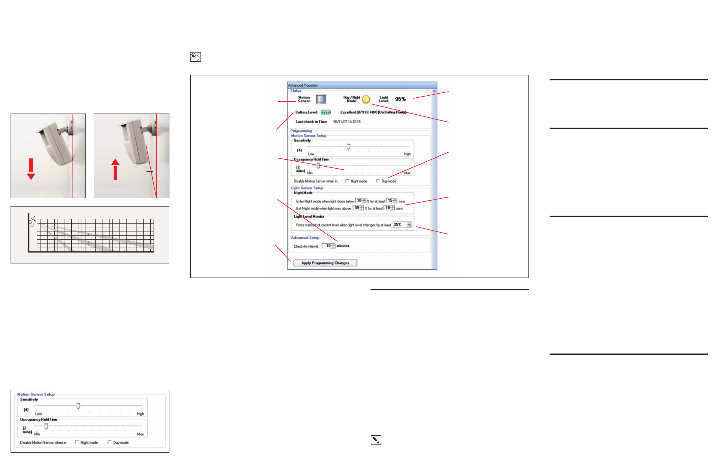
8. Advanced Settings
The Composer Properties Page allows for advanced configuration of Motion
Sensor and Light Sensor properties.
Several characteristics of the InHome Wireless Motion Sensor can be programmed and are described in the following diagram:
NOTE: The below property page and the associated descriptions are
subject to change. For the latest description of the driver feature set
and product operation go to www.cardaccess-inc.com/inhome
9. Troubleshooting
If the InHome Wireless Motion Sensor is not working:
• Reset the Wireless Motion Sensor by disconnecting the battery from the
unit, waiting ten (10) seconds,and then reconnecting power.
To check for proper radio operation,do the following:
• Ensure that the motion sensor is in the desired location and has been added
to a Composer Project.
• Press and hold the button (located under the battery cover) for at least 3
seconds. This will put the InHome Wireless Motion Sensor into “Radio Test
Mode” for the next 3 minutes allowing for radio performance observation.
This mode can only be used after you have registered the unit into the
Composer Project. The test repeatedly sends a signal to the controller, waits
for a response, and indicates success (green) or failure (red) by LED. The
indicating LED will remain lit for approximately 3 seconds before repeating
the test. An occasional red LED is normal. Excessive red LEDs may indicate
RF interference or a range problem. If this is the case you may need to
move the unit to achieve improved performance.
Contact us:
For help on the installation or operation of this product, email or call Card
Access Product Support. Please provide your exact model number and
the MAC ID/Serial Number for the device. You may contact Product Support
by phone (801-748-4900, extension 15), by e-mail
(inhomesupport@cardaccess-inc.com) or on the Internet at
www.cardaccess-inc.com/inhome/support.
Regulatory Compliance
The Card Access InHome Wireless Motion Sensor complies with standards established by the following regulatory bodies: Federal Communications Commission (FCC), Conformité Européene
(CE), and Restriction of Hazardous Substances (RoHS).
FCC
FCC ID: MHIWMS
This device complies with Part 15 of the FCC Rules. Operation is subject to the following two conditions: (1) this device may not cause harmful interference, and (2) this device must accept any
interference received, including interference that may cause undesired operation.
This equipment has been tested and found to comply with the limits for a Class B digital device,
pursuant to Part 15 of the FCC Rules. These limits are designed to provide reasonable protection
against harmful interference in a residential installation. This equipment generates, uses, and
can radiate radio frequency energy and, if not installed and used in accordance with the instructions, may cause harmful interference to radio communications. However,there is no guarantee
that interference will not occur in a particular installation. If this equipment does cause harmful
interference to radio or television reception, which can be determined by turning the equipment
off and on, the user is encouraged to try to correct the interference by one or more of the following measures:
• Reorient or relocate the receiving antenna.
• Increase the separation between the equipment and receiver.
• Connect the equipment into an outlet on a circuit different from that to which
the receiver is connected.
• Consult the dealer or an experienced radio/TV technician for help.
IMPORTANT! Changes or modifications not expressly approved by
Card Access, Inc. void the user’s authority to operate the equipment.
CE
We,Card Access, Inc. of 11778 South Election Road, Suite 260, Salt Lake City,Utah, 84020
USA, declare under our sole responsibility that the Card Access InHome Wireless Motion Sensor,
Model Numbers WMS10 and WMS10-EXT, to which this declaration relates, are in conformity with
the following standards and / or other normative documents:
EN60950, EN55022, EN55024
We hereby declare that the above named product is in conformity with the essential requirements
and other relevant provisions of Directive 1999/5/EC.
The conformity assessment procedure referred to in Article 10(3) and detailed in Annex II of
Directive 1999/5/EC has been followed.
Restriction of Hazardous Substances (RoHS)
All parts in the Card Access InHome Wireless Motion Sensor meet the material restrictions of
RoHS, as proposed by the RoHS Technical Adaptation Committee. This is based upon information
provided by suppliers of the raw materials used by Card Access,Inc. to manufacture these products. As such, Card Access, Inc. makes no independent representations or warranties, expressed
or implied, and assumes no liability in connection with the use of this information.
Product Registration
Please visit www.cardaccess-inc.com/inhome/registration to register your new product. Along
with your contact information, you must provide the following additional information:
• Product Name (Card Access InHome Wireless Motion Sensor)
• Model Number (WMS10 or WMS10-EXT)
• Date of Purchase
• Place of Purchase
• Serial Number (this is the “MAC ID” located on the sticker attached to the
radio/logic board inside the battery compartment)
Please refer to the One-Year Limited Warranty for complete warranty information.
One-Year Limited Warranty
This product is warranted to be free of defects in material and workmanship for one year from date
of original purchase from Card Access, Inc. (“Card Access”).
Card Access will, at its election and as the purchaser’s or end user’s sole and exclusive remedy
for any breach of the limited warranty set forth above, repair or replace this product if a defect in
material or workmanship is identified and communicated to Card Access within the one-year period described above. Card Access is not responsible for removal or reinstallation costs. This warranty is not valid in cases where damage to this product is the result or arises out of misuse,
abuse, incorrect repair or improper wiring or installation.
To notify Card Access of any breach of the foregoing limited warranty and to obtain warranty service, contact Card Access Customer Support by e-mail to support@cardaccess-inc.com or by calling 801-748-4900, extension 15, to obtain a Return Materials Authorization (“RMA”) number and
instructions for returning your defective product to Card Access.
IMPLIED WARRANTIES,INCLUDING THOSE OF MERCHANTABILITY AND FITNESS FOR A P ARTICULAR PURPOSE, ARE EXPRESSLY DISCLAIMED, EXCEPT WHERE SUCH DISCLAIMER IS PROHIBITED
BY APPLICABLE LAW . CARD A CCESS AND/OR THE SELLER DISCLAIM(S) ANY AND ALL LIABILITY
FOR SPECIAL, INCIDENTAL AND CONSEQUENTIAL DAMAGE IN ANY WAY ASSOCIATED WITH OR
RELATED TO THE PURCHASE,INSTALLATION AND/OR USE OF THIS PRODUCT.
Some states/provinces do not allow limitations on how long an implied warranty lasts, or the
exclusion or limitation of special, incidental or consequential damages, so these limitations and
exclusions may not apply to you. This warranty gives you specific legal rights. You may also have
other rights which vary from state/province to state/province.
About This Document
Copyright © 2007, Card Access, Inc. All rights reserved.
Card Access, InHome and Wires Not Included are trademarks of Card Access, Inc.
ZigBee is a trademark of the ZigBee Alliance.
Control4 is a registered trademark of Control4 Inc.
Other marks may be the property of their respective owners.
QSG-WMS-INST10
Move the sensor downward
to reduce the range.
Move the sensor up to around
12º to maximize range.
12º
Indicates current motion
sensor status
Indicates current battery level
Indicates current amount
of light detected
Indicates current mode of
operation (Day/Night)
Allows Motion Sensor function
to be disabled when in Day
or Night mode (also conserves
battery life)
Controls light level and time
required before Night mode is
toggled
Instructs the Wireless Motion
Sensor to send an updated light
level to the Zigbee network
when light level changes by at
least the specified percent.
Lower values can compromise
battery life
Click to program
settings into the device
Instructs the Wireless Motion Sensor
to send a periodic update of
Motion status and light level. Only
change if needed.Lower values can
compromise battery life
Controls how long the Motion Sensor
will look for absence of motion
before triggering a No Motion
Detected event
Detection area
12º
8’
6’
4’
2’
O’
10’ 15’ 20’ 25’ 30’5’
 Loading...