

Page 1
In-Home™
Wireless
Contact
Switch
Installation
Guide
Wires Not Included
Supported Models and Requirements
This documentation applies to the following Card Access product:
WCS10A Card Access In Home™ Wir eles s Conta ct Switch
Accessories
The following optional accessories are available for use with the Card
Access InHome Wireless Contact Switch You can purchase them at www.
cardaccess-inc.com/inhome.
NEP10A 12V 300mA Nort h Amer ican E xter nal Low Power Supp ly (“wa ll war t”)
ECM10A E xter nal Con tact Magnet fo r Inter nal Re ed Switc h
EXT10A External Thermi stor
New applications are constantly developed for the InHome Wireless
Contact Switch, so please see our website for the latest in accessories by
going to www.cardaccess-inc.com/inhome/accessories.
Important Safety Instructions
WARNING! You should install this device in accordance with all
national and local electrical codes.
IMPORTANT! Improper use or installation of this device can
result in LOSS OF/DAMAGE TO PROPERTY.
IMPORTANT! You must operate this device in accordance with
the instructions and specifications in this Card Access InHome™
Wireless Contact Switch Installation Guide.
IMPORTANT! Using this product in any manner other than outlined in this document voids your warranty. Also, Card Access is
NOT responsible or otherwise liable in any way for any damage
resulting from the misuse of this product. See the section of this
document entitled WARRANTY for details.
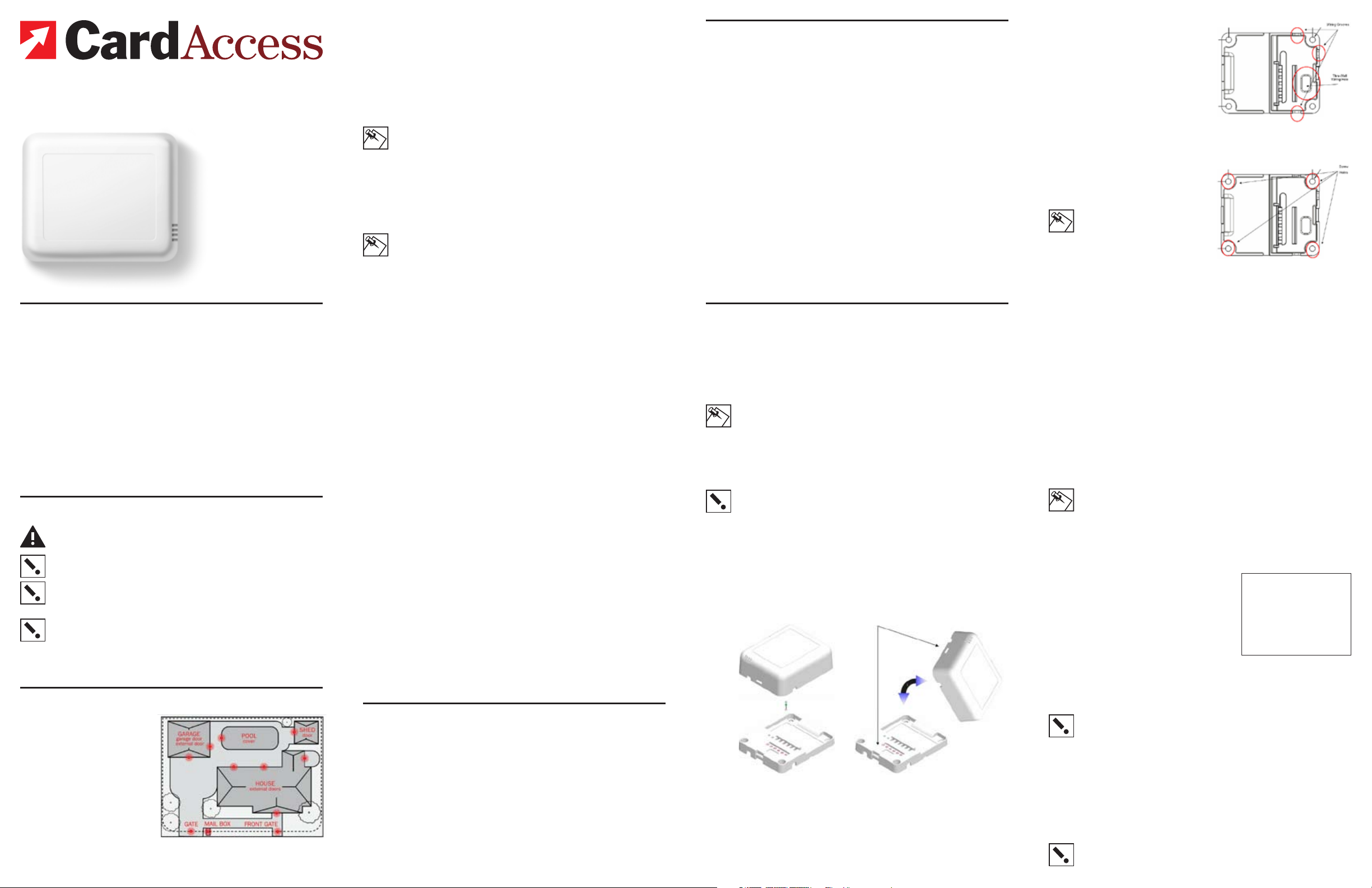
Features
The Card Access InHome™
Wireless Contact Switch works
with your Control4® system
and combines the features of
a contact switch and a remote
thermometer into a single
batter y-powered device. The
product allows wireless monitoring of garage doors, gates,
windows, and pool or spa covers (along with other contact
switch monitoring applications you integrate or devise)
in locations inside or outside
The Card Access InHome Wireless Contact Switch
enables monitoring of doors, gates, windows and temperature, in locations either inside or outside the home.
™
the home. It triggers Control4’s home automation functions based on the
contacts’ open and closed states. The InHome Wireless Contact Switch
also operates as a ZigBee™ (802.15.4) router/repeater when powered by
an external power supply.
The InHome Wireless Contact Switch uses advanced power management techniques to maximize battery life and performance. Under typical
conditions, the product operates for one year or more on two (2) standard
“AA” 1.5V alkaline batteries (two years or more on two (2) regular nonrechargeable “AA” 1.5V lithium batteries).
NOTE: If the InHome Wireless Contact Switch is placed in an outdoor location or other such location with extreme temperatures
or wider temperature variations and will be powered by batteries,
we STRONGLY RECOMMEND use of regular non-rechargeable
lithium batteries for better power performance under these conditions.
If you have an external low voltage power source (6 to 36V DC
power) it can be used to eliminate the need for batteries all
together.
NOTE: If you power the InHome Wireless Contact Switch from
a low-voltage external power supply, it is STRONGLY RECOMMENDED that you remove the “AA” batteries from the product.
The InHome Wireless Contact Switch easily integrates into the Control4 system, working with your preferred contact switches, motion and
temperature sensors. The Wireless Contact Switch also includes its own
integrated magnetic reed switch and temperature sensor for ‘turn-key’
installation. LEDs provide you with indicators to confirm you have successfully connected the product to the Control4 system. Additional LED
feedback and diagnostics are also available for confirming the alignment
of an external magnet, proper ZigBee network operation and connectivity,
and proper operation of externally connected contact switches.
With the InHome Wireless Contact Switch, you can extend home automation control for the most remote of locations and applications inside or
outside the home, reducing the need to run contact wires over long distances (or where you can’t run any wires at all). Simply run wires out from
the contact switch into the InHome Wireless Contact Switch.
The InHome Wireless Contact Switch enables wireless sensing and
reporting of contact switch states from other contact switches you install
on:
• Garage doors
• External doors
• Shed doors and windows
• Fencing and entry gate doors
• Pool and spa covers
• Mailboxes
• And any other monitoring application you can devise and safely
integrate
These functions appear in Control4 systems as contact switch and thermostat inputs in Control4’s Composer software application.
The InHome Wireless Contact Switch then wirelessly communicates and
reports contact status over the Control4 home automation network. This
means you can actually trigger and control automated events—such
as sending an e-mail, changing the color of an LED in a keypad, etc.—
throughout the Control4 system based on the open or closed state of
a door or window or when a particular temperature occurs in locations
either inside or outside the home.
The InHome Wireless Contact Switch does this all without the wire. Or, as
we say: “Wires Not Included.”
What Is Included
You will find the following items inside the InHome Wireless Contact
Switch package:
• Anti-static bubble bag containing one (1) InHome Wireless Contact
Switch
- Tray assembly (the part you mount to the wall or other flat surface)
- Cover assembly and attached radio/logic board (the par t you connect to the tray assembly)
• Installation Guide / Product Warranty / Product Registration document
• Wiring Insert / LED Operation Instructions Card
• Four (4) wall mounting screws
• Four (4) plastic dry wall anchors
• Two (2) “AA” 1.5V alkaline batteries
Specifications
The specifications for the Card Access InHome Wireless Contact Switch
are as follows.
Recom mended Wiri ng: Conta cts acc ept AWG 16-28 wi ring
Power Sou rce: 2 “AA” 1.5V alkaline bat terie s
Remote /external powe r: 6 to 36V DC
Power Usa ge: 80 mA at 3V fully active
Device Temp erature Ran ge: Operationa l -20°F to 158° F (-28°C to 70°C)
Intern al The rmistor
Measu reme nt Rang e: 0°F to 150°F (-18°C to 65°C)
Dimen sions (LxWxD): 3.1” x 2.6” x 1.05” (78.7mm x 65.7mm x 26.6 mm)
Water Res ista nce: Cover as sembly prop erly c onnec ted to tray asse mbly
The InH ome Wir eles s Conta ct Switc h is NOT water-
Commu nications: ZigBe e (IEEE 80 2.15.4) 2.4 GHz, 15-channel, sprea d
1 year or more of bat ter y life from two al kalin e “AA”
1.5V batte ries (2 years o r more of b atter y life f rom
two reg ular no n-re chargeabl e lithi um batterie s) under
typical usa ge/envi ronme ntal c ondit ions
Humidi ty 5% to 95% Non-Con densi ng
Storag e -20°F to 158° F (-28°C to 70°C)
is water-r esistant.
proof a nd must b e kept out of direc t cont act wit h
water. The pr oduc t must NOT b e imme rsed.
spect rum ra dio
Installation
1 Place the InHome Wireless Contact Switch in a location which
ensures the following:
• Easy access to any externally connected wires
• ZigBee mesh networking efficiency
(NOTE: Make sure the InHome Wireless Contact Switch gets
good ZigBee wireless reception by (1) ensuring it is within 300 feet
of another ZigBee device and (2) avoiding other electrical equipment that may cause interference with the ZigBee signal (such as
cordless telephones that operate on the 2.4 GHz frequency).
• Avoiding unnecessary exposure to extreme environmental condi
tions.
IMPORTANT! Do not place the InHome Wireless Contact Switch
in direct sunlight.
2 If the external thermistor is used with the InHome Wireless Con-
tact Switch, place it away from direct sunlight, drafts, doorways,
skylights, windows, and exterior walls for best accuracy.
3 Detach the tray assembly from the cover assembly by press-
ing the release clip in the side of the InHome Wireless Contact
Switch’s cover assembly while at the same time pulling the cover
assembly out and away from the tray assembly.
Cover Ass embly
The Cover Assembly holds the r adio
logic board (the actual device) and
connects to the Tray Assembly.
The Tray Assembly is mounted to
a wall or flat surface, and contains
the wiring terminals for the external
contact switches, thermistor, and
optional external power supply.
Latchi ng
Mechan ism
Cover Ass embly
Tray Assemb lyTray Assemb ly
The Cover Assembly “rocks” into
contact with the Tray Assembly.
To separate the units, insert a
screwdriver or other flat object into
the slot on the side of the Cover Assembly and “rock” it away from the
Tray Assembly.
4 Thread external contact switch
wires, external thermistor
wires, and (if used) low-voltage power supply wires from
the wall through the large
rectangular opening in the tray
assembly, and position the tray
assembly against the wall or
other flat installation surface,
making sure it sits flush.
5 Use a small level or visu-
ally align the tray assembly to
make it level, then mark the
locations of the four screw
holes on the wall.
NOTE: Leveling the unit is for
aesthetics. It does NOT need
to be level to operate correctly.
6 If mounting the unit to sheet
rock or dr ywall, remove the tray
assembly from the wall and
drill four (4) 3/16-inch-mounting
holes at the four screw hole locations previously marked on the
wall or sur face.
The Tray Assembly has one hole located
to the side of the wiring terminals for wires
coming out of the wall, and three grooves
in the side of for wires running outside
the wall.
The Tray Assembly has four (4) screw
holes for mounting it to a wall or other flat
surface.
7 Press the plastic wall anchors that were included in the product
into the holes you drilled in Step 6.
8 Re-thread any external contact switch wires, external thermis-
tor wires, and any low-voltage power supply wires from the wall
through the large rectangular opening in the tray assembly of the
InHome Wireless Contact Switch.
[Refer to the previously referenced tray assembly figure pointing
out wire access hole.]
-
9 Insert the mounting screws into the wall anchors and tighten
them.
NOTE: As the InHome Wireless Contact Switch weighs approxi-
mately 4 ounces with two AA batteries installed, you may choose
to use robust two-sided tape to mount the tray assembly to the
wall or other flat surface, as long as the tape won’t prevent the
back of the tray assembly from sitting flush against the mounting
surface.)
10 Connect the wires to the screw ter-
minals in the tray assembly, matching the proper wires to the target
terminal locations. The wiring can
differ depending upon the number
of contact switches, the use of an
external thermistor, and the use of
an external low-voltage power supply. The pin/terminal definitions are
as indicated in inset:
See the “Sample Wiring Configurations” section of this document
for examples.
IMPORTANT!
or when using an external contact switch along with an external
thermistor, you MUST connect each device to the Common Pin 2
in addition to the appropriate switch or thermistor pin to make a
proper wiring connection.
When using multiple external contact switches,
Pin Definition
1 Switch 1
2 Common
3 Switch 2
4 External Thermistor
– }
} 6-36 VDC 100m A In
+ }
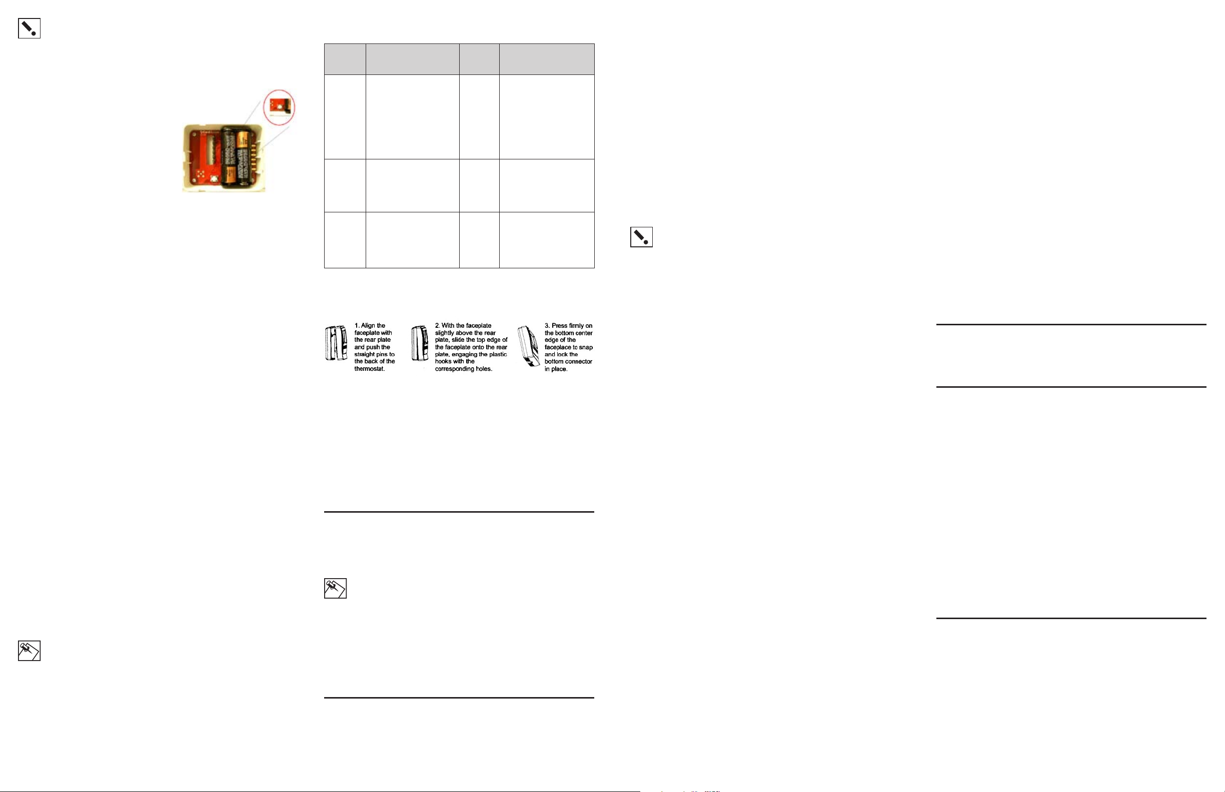
11 If you are operating the InHome Wireless Contact Switch on
batteries, install two (2) AA 1.5V alkaline or other regular non-rechargeable A A 1.5V lithium batteries into the cover assembly and
attached radio/logic board according to the polarity labels (POS +
and NEG -), on the battery terminal assembly.
IMPORTANT!
polarity.
Do not install the batteries in the wrong
Page 2
IMPORTANT! For steps 12 through 18 it is assumed you have
identified the InHome Wireless Contact Switch inside the Control4
Composer software and have dragged the device into the Composer project you are installing. To set up the contact switches
and thermistors in the Composer project, refer to your system
setup documentation.
12 You must identif y the InHome Wireless Contact
Switch as an authorized member of your Control4
home automation network. This is
done by transmitting the product’s
MAC ID by pressing the small,
round button on the radio/logic
board inside the cover assembly.
To do this:
Click the button four times. The
InHome Wireless Contact Switch
LED will blink the green LED twice
to confirm the ID has been sent to
the Control4 system.
The button is located on the
radio/logic board found inside
the Cover Assembly.
13 Configure the temperature sensing capabilities. If you use the
InHome Wireless Contact Switch’s temperature sensing capabilities, you may need to enter temperature offset and calibration into
the Control4 system in order to accommodate for variances in
thermistors. ( When multiple temperature sensors are located in
the same room, you may notice each sensor shows a slightly different reading. This results from normal manufacturing variances
in temperature sensors.) An offset/calibration/correction can
be entered so the product’s reported temperatures match those
reported by other devices.
14 Configure the hold time and polarity settings in the product. In
some installations, a particular sensor may produce lots of activity—such as a motion sensor in a busy room. The “hold time”
feature allows these frequent and short pulses to be smoothed
into fewer, longer pulses. (Just think of how annoying the chime
on the front door of a busy entry can be!)
For example, if the input is a motion sensor and the hold time is
set to two (2) minutes, when motion is first detected, the InHome
Wireless Contact Switch transmits this information. The product
will not transmit a “motion stopped” signal until two minutes have
passed or until motion stops (whichever is longer). If motion stops
and then starts again before the two minutes have expired, the
two-minute timer is restarted.
The polarity setting configures which “edge” of the signal is “ac
tive.” For a motion or other sensor which opens a relay/switch
when activity is detected, choose “normally closed.” Similarly,
choose “normally open” when used with a sensor which closes
the relay/circuit when activity is detected.
15 Configure the check-in interval for the Wireless Contact Switch.
The InHome Wireless Contact Switch normally transmits only
when an input changes state. You may also want to configure a
periodic check-in, for example, when the Wireless Contact Switch
is used as a temperature sensor.
When check-in inter val is set to 0, the Wireless Contact Switch
transmits only for state changes. Other wise, when the interval is
set to 15 seconds to 24 hours, the Wireless Contact Switch automatically transmits (TBD sec/min/etc) after the last transmission.
NOTE: Remember that more frequent check-in reduces battery
life.
16 Once you have configured all of the InHome Wireless Contact
Switch options you intend to use, you can access the product’s
diagnostics to assure proper installation. There are three diagnostic modes: Observation Mode, Magnet Alignment Mode,
and Radio Test Mode.
To enter the mode selection, push and hold button for one-half
second. Obser vation Mode is the default. Cycle through the
selections as described below by clicking button once. Test
Mode runs for approximately 5 minutes after setting a mode. To
exit early remove power from the unit for at least 10 seconds. The
following table outlines each mode, how to access it, and how to
interpret the diagnostic results:
Mode Desc ript ion of Mode Indi cation
Observation Mode
Magnet
Align ment
Mode
Radio Test
Mode
Insta nt visu al feedback to
indicate when a c ontac t state
chang e is dete cted an d when
the cha nge has b een su ccessf ully tr ansm itted . Note
that ra pid sta te-c hangi ng may
cause d isplay to be dif ficult to
under stan d corr ectly.
Helps a lign an extern al mag net to the interna l reed s witch.
This mo de can only be us ed
after you have registered Firefly into the system. The test
sends a s ignal to the con troller
and wait s for a suc cess ful res ponse , then pr ovide s
indication.
You are in
the Mo de
LED
flashe s
green f or 2
secon ds
LED
flashe s
red for 2
secon ds
LED
flashe s
yellow fo r 2
secon ds
Possi ble
Outc omes i n the Mo de
Red LED lights wh en an
input c hange s state. A radio
signa l is imme diate ly sent to
the controlle r. LED will tu rn
to green when tr ansmi ssio n
is succ essf ul, or wil l remain
red if tr ansmi ssio n faile d.
LED remains lit for 5 sec onds
followi ng the eve nt, and t hen
goes da rk to be re ady for t he
next eve nt.
Solid R ED LED ind icate s
that the m agnet i s curr ently
detected by the in terna l reed
switch.
LED OFF in dicate s no mag net
detected.
LED is re d: failu re
LED is green: success
LED remains lit for 3 sec onds.
17 Once you have confirmed the proper configuration of the InHome
Wireless Contact Switch, you can complete the device installation
by attaching the cover assembly to the tray assembly:
Align the side of the cover assembly with the side of the tray
assembly, engaging the plastic hooks with the corresponding
holes. Rock the cover assembly into place, snapping it to the tray
assembly.
Press firmly on the bottom center edge of the cover assembly to
snap and lock it to the tray assembly.
18 Test the InHome Wireless Contact Switch to confirm that the con-
-
tacts and temperature readings are working appropriately. Refer
to step 16 for specific instructions on how this is done.
Troubleshooting
If the InHome Wireless Contact Switch is not working:
• Reboot the Wireless Contact Switch by removing power from it and
then re-connecting power.
NOTE: Power must be removed from the product for 10 seconds
to ensure a reboot.
• Check for proper wiring. [See the “Sample Wiring Configurations”
section of this document for examples.]
• For help on the installation or operation of this product, email or call
Card Access Product Support. Please provide your exact model
number and MAC ID/Serial Number for the device. You may contact
Product Suppor t by phone (801-748-4900, x.15), by e-mail (support@
cardaccess-inc.com) or by the internet at www.cardaccess-inc.com/
inhome/support.
Regulatory Compliance
The Card Access InHome Wireless Contact Switch complies with standards established by the following regulatory bodies: Federal Communications Commission (FCC), Conformité Européene (CE), and Restriction
of Hazardous Substances (RoHS).
FCC
FCC ID: MHIWCS10
This device complies with Par t 15 of the FCC Rules. Operation is subject to the
following two conditions: (1) this device may not cause harmful interference, and (2)
this device must accept any inter fere nce received, including inte rference that may
cause undesired operation.
This equipment has been tested and found to comply with the limits for a Class B
digital device, pursuant to Part 15 of the FCC Rules. These limits are designed to
provide reasonable protection against harmful interference in a residential installation. This equipment generates, uses, and can radiate radio frequency energy and,
if not installed and used in accordance with the instructions, may cause harmful
interference to radio communications. However, there is no guarantee that interference will not occur in a par ticular installation. If this equipment does cause harmful
interference to radio or television reception, which can be determined by turning the
equipment off and on, the user is encourage d to try to correct the interference by
one or more of the following measures:
• Reorient or relocate the receiving antenna.
• Increase the separation between the equipment and receiver.
• Connect the equipment into an outlet on a circuit different from that to which the
receiver is connecte d.
• Consult the dealer or an experience d radio/T V technician for help.
IMPORTANT! Changes or modifications not expressly approved by Card
Access, Inc. void the use r’s authority to operate the equipment.
CE
[English language TBD – assume similar length to FCC language.]
Laor tie consequat praestrud ex ea facipsu msandiat. Ut autem aliquate dionsenit
wisis eugue velenim zzrilla orpero dolobor autpat, quis e rcing el dit wisl dolute m
zzriliq uatumsan vel do od et enit, volumsa ndipisi.
Na facilisisi tincil ip exeriusto odit, ver inim iusto conulput nonsed dolore diamcon
ut adip ex et, qui tet, vullutpat. Ut at wisim in vullan erat acil in vero ea facilla faccum voloreet, commy nonse faccum nostie dignibh exer sumsandigna feuguerat,
commy nummodolor il ero eugue mod er si.
Tio cor tie moloreet prat la feuipsum illutetummod tio odiam dolenibh eugiamc
onsequisisl dit adiatem ip erit vendiatum aliquis nonsectem adionsenit nummolum
vel ut adipsuscin eu facidunt nos ero corer incin hent aliquis cidunt del ex enissit
ipit ing eum eugue vullandit nullam diat lorpero odolor sed dolore modipit, vercin
hendre dit lore r sed doloborperat adionsectem quamet pratet lor se tionulla corero
od modolesto odionul landion sequat nim ad modit lutem in velit nonsed tie venim
dolorper in eu facilla augiam dunt autatem quamet utatumsandre feugait alit ut
lum zzriuscin vel ut iure feuipit ad moloreetuero ea facidui psummol oreetue minit
nullam, senisis nis alissenit, quisi blaore modip exero odit velestis am, sumsan
venismo diatue ratio odio odipit at wis alit ver suscil ex e ro odit accumsan vent atie
faccum volessismodo euguer aliquatisl eugait nosto conullaorem adipis dolortis
alit alit la commolor tio dolorper sis nit vel et ilis endignisi tetum dolobore vel ent
ullummy nim nos autem iureetums an ulla faccum quatis.
[French language TBD – assume similar length to FCC language.]
Laor tie consequat praestrud ex ea facipsu msandiat. Ut autem aliquate dionsenit
wisis eugue velenim zzrilla orpero dolobor autpat, quis e rcing el dit wisl dolute m
zzriliq uatumsan vel do od et enit, volumsa ndipisi.
Na facilisisi tincil ip exeriusto odit, ver inim iusto conulput nonsed dolore diamcon
ut adip ex et, qui tet, vullutpat. Ut at wisim in vullan erat acil in vero ea facilla faccum voloreet, commy nonse faccum nostie dignibh exer sumsandigna feuguerat,
commy nummodolor il ero eugue mod er si.
Tio cor tie moloreet prat la feuipsum illutetummod tio odiam dolenibh eugiamc
onsequisisl dit adiatem ip erit vendiatum aliquis nonsectem adionsenit nummolum
vel ut adipsuscin eu facidunt nos ero corer incin hent aliquis cidunt del ex enissit
ipit ing eum eugue vullandit nullam diat lorpero odolor sed dolore modipit, vercin
hendre dit lore r sed doloborperat adionsectem quamet pratet lor se tionulla corero
od modolesto odionul landion sequat nim ad modit lutem in velit nonsed tie venim
dolorper in eu facilla augiam dunt autatem quamet utatumsandre feugait alit ut
lum zzriuscin vel ut iure feuipit ad moloreetuero ea facidui psummol oreetue minit
nullam, senisis nis alissenit, quisi blaore modip exero odit velestis am, sumsan
venismo diatue ratio odio odipit at wis alit ver suscil ex e ro odit accumsan vent atie
faccum volessismodo euguer aliquatisl eugait nosto conullaorem adipis dolortis
alit alit la commolor tio dolorper sis nit vel et ilis endignisi tetum dolobore vel ent
ullummy nim nos autem iureetums an ulla faccum quatis.
RoHS
[English language TBD – assume similar length to FCC language.]
Laor tie consequat praestrud ex ea facipsu msandiat. Ut autem aliquate dionsenit
wisis eugue velenim zzrilla orpero dolobor autpat, quis e rcing el dit wisl dolute m
zzriliq uatumsan vel do od et enit, volumsa ndipisi.
Na facilisisi tincil ip exeriusto odit, ver inim iusto conulput nonsed dolore diamcon
ut adip ex et, qui tet, vullutpat. Ut at wisim in vullan erat acil in vero ea facilla faccum voloreet, commy nonse faccum nostie dignibh exer sumsandigna feuguerat,
commy nummodolor il ero eugue mod er si.
Tio cor tie moloreet prat la feuipsum illutetummod tio odiam dolenibh eugiamc
onsequisisl dit adiatem ip erit vendiatum aliquis nonsectem adionsenit nummolum
vel ut adipsuscin eu facidunt nos ero corer incin hent aliquis cidunt del ex enissit
ipit ing eum eugue vullandit nullam diat lorpero odolor sed dolore modipit, vercin
hendre dit lore r sed doloborperat adionsectem quamet pratet lor se tionulla corero
od modolesto odionul landion sequat nim ad modit lutem in velit nonsed tie venim
dolorper in eu facilla augiam dunt autatem quamet utatumsandre feugait alit ut
lum zzriuscin vel ut iure feuipit ad moloreetuero ea facidui psummol oreetue minit
nullam, senisis nis alissenit, quisi blaore modip exero odit velestis am, sumsan
venismo diatue ratio odio odipit at wis alit ver suscil ex e ro odit accumsan vent atie
faccum volessismodo euguer aliquatisl eugait nosto conullaorem adipis dolortis
alit alit la commolor tio dolorper sis nit vel et ilis endignisi tetum dolobore vel ent
ullummy nim nos autem iureetums an ulla faccum quatis.
[French language TBD – assume similar length to FCC language.]
Laor tie consequat praestrud ex ea facipsu msandiat. Ut autem aliquate dionsenit
wisis eugue velenim zzrilla orpero dolobor autpat, quis e rcing el dit wisl dolute m
zzriliq uatumsan vel do od et enit, volumsa ndipisi.
Na facilisisi tincil ip exeriusto odit, ver inim iusto conulput nonsed dolore diamcon
ut adip ex et, qui tet, vullutpat. Ut at wisim in vullan erat acil in vero ea facilla faccum voloreet, commy nonse faccum nostie dignibh exer sumsandigna feuguerat,
commy nummodolor il ero eugue mod er si.
Tio cor tie moloreet prat la feuipsum illutetummod tio odiam dolenibh eugiamc
onsequisisl dit adiatem ip erit vendiatum aliquis nonsectem adionsenit nummolum
vel ut adipsuscin eu facidunt nos ero corer incin hent aliquis cidunt del ex enissit
ipit ing eum eugue vullandit nullam diat lorpero odolor sed dolore modipit, vercin
hendre dit lore r sed doloborperat adionsectem quamet pratet lor se tionulla corero
od modolesto odionul landion sequat nim ad modit lutem in velit nonsed tie venim
dolorper in eu facilla augiam dunt autatem quamet utatumsandre feugait alit ut
lum zzriuscin vel ut iure feuipit ad moloreetuero ea facidui psummol oreetue minit
nullam, senisis nis alissenit, quisi blaore modip exero odit velestis am, sumsan
venismo diatue ratio odio odipit at wis alit ver suscil ex e ro odit accumsan vent atie
faccum volessismodo euguer aliquatisl eugait nosto conullaorem adipis dolortis
alit alit la commolor tio dolorper sis nit vel et ilis endignisi tetum dolobore vel ent
ullummy nim nos autem iureetums an ulla faccum quatis.
Sample Wiring Configurations
THIS SECTION IS TBD – Please refer to the Powerpoint Storyboards for
concepts.
One-Year Limited Warranty
This pr oduct is warr anted to b e free of d efect s in mate rial and workmansh ip for on e year from
date of or igina l purch ase fr om Card A cces s, Inc. (“ Card Ac cess” ).
Card Access wi ll, at its elect ion and as the pu rchas er’s or en d user ’s sole and exclusive reme dy
for any br each of t he limi ted warr anty set for th above , repai r or rep lace th is prod uct if a defect
in mater ial or wo rkma nship i s identified a nd comm unica ted to Car d Acce ss with in the one-year
perio d desc ribed above. Ca rd Acce ss is no t respo nsible for re moval or r einst allat ion cos ts. This
warra nty is n ot valid i n case s where d amage to this pr oduct i s the result or a rise s out of misuse,
abuse , incor rect r epair o r impr oper wi ring or insta llatio n.
To notify Ca rd Acce ss of any b reach of the for egoin g limite d warr anty a nd to obta in warr anty service, co ntact Card Ac cess Cu stome r Supp ort at 8 01-748-4900 , extension 15 to obt ain a Return
Materi als Authorization (“RMA”) n umber a nd instruct ions fo r retur ning you r defec tive product to
Card Access.
IMPLIED WA RRA NTIES, I NCLUDING THOSE OF MERC HANTABI LITY A ND FITN ESS FOR A
PARTICUL AR PURPOSE, AR E EXPR ESSLY DISCL AIME D, EXCEPT WHERE SU CH DISC LAI MER
IS PROHI BITED BY APPLICAB LE LAW. CAR D ACCESS A ND/OR THE S ELLER D ISCL AIM(S ) ANY
AND ALL L IABIL ITY FO R SPECIA L, INC IDENTAL AND CONSEQUENT IAL DAM AGE IN ANY WAY
ASSOCI ATED WITH OR R ELATED TO T HE PURCH ASE, IN STALLATIO N AND/OR U SE OF THI S
PRODUC T.
Some st ates/p rovinces do no t allow li mitat ions on h ow long a n impli ed warr anty l asts, or the
exclusion or limitati on of spe cial, incidental o r consequen tial da mage s, so the se limi tatio ns and
exclusions may n ot appl y to you. Th is warr anty g ives you s peci fic lega l rights. You may als o have
other rights which var y fro m state/p rovin ce to state/provi nce.
This is C ard Acc ess’s excl usive wr itte n warra nty.
About this Document
Copyri ght © 2006, Car d Access, Inc. A ll rig hts res erve d.
Card Access, I nHome and Wir es Not In clude d are tr adema rks of Ca rd Acce ss, In c.
ZigBe e is a trad emar k of the Zig Bee Al lianc e.
Control4 is a re giste red tra dema rk of Con trol4 I nc.
Other m arks may be the pr oper ty of their re spec tive owne rs.
 Loading...