

C.A.R.D. 60 Installation And Operation Manual
®
C.A.R.D. MODEL 060
INSTALLATION AND OPERATION MANUAL
SURVIVAL SAFETY ENGINEERING
INCORPORATED
321 NAVAL BASE ROAD
NORFOLK, VIRGINIA 23505
USA
Phone (757) 480-5508 Toll Free 888 475-5364
Email: survivalsafety@cox.net
www.survivalsafety.com
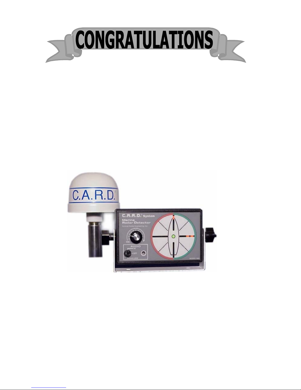
You have just purchased one of the most important devices
you will ever buy for your vessel.
®
C.A.R.D. Model 060, Collision Avoidance Radar Detector is
the finest Radar Detector on the market today.
It uses the same detector principles as the Model 100 Units
that have performed so well under rigorous conditions for
the U.S. Navy.
WARNING !
This device is intended for use as an aid to collision
avoidance only. It does not in any way, relieve or reduce the
responsibility of the Captain of the vessel for maintaining a
proper watch at all times when underway as described in the
Code of Federal Regulations and International Maritime
Law.

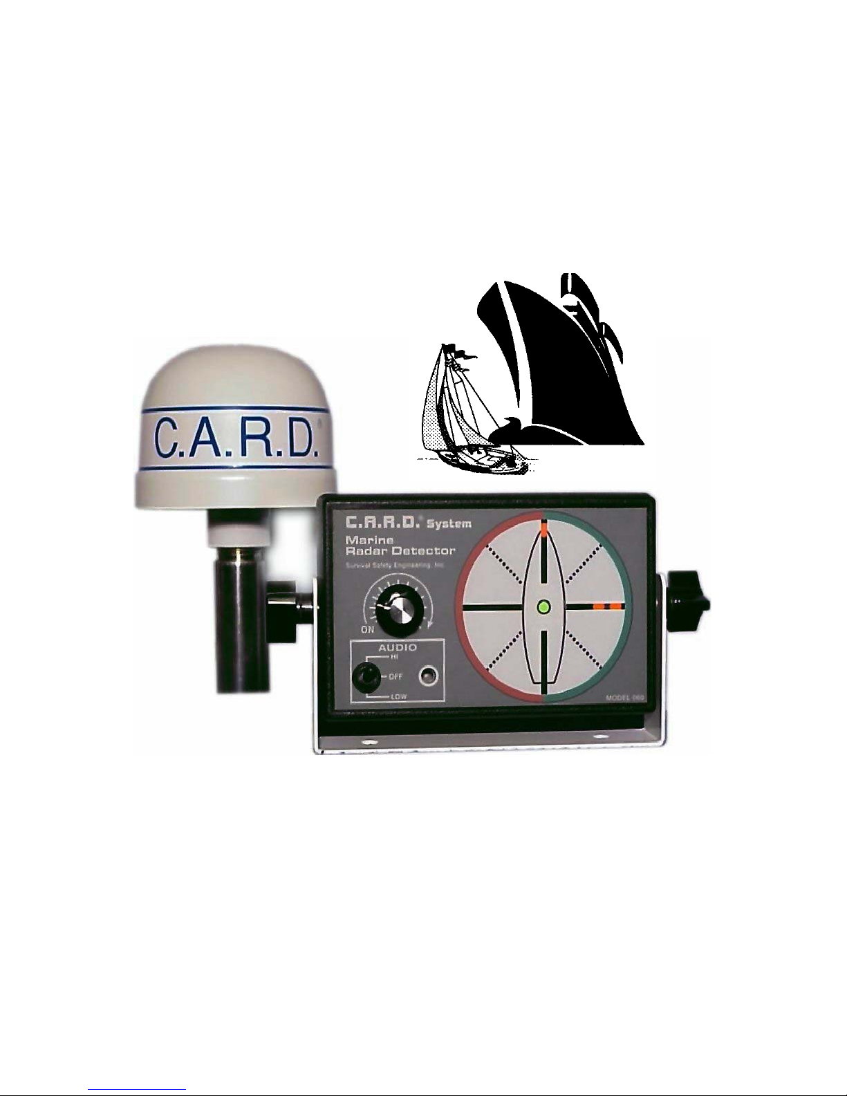
C.A.R.D. SYSTEM COMPONENTS
The Antenna with a standard 25 foot cable
The Display Unit (Control Module)
This Manual
INDEX:
Warning Page 2
Components Page 3
How your C.A.R.D. system works Page 4
Antenna Installation Page 5,6
Antenna Unit Page 7
Control Module Warning Page 8
Control Module Page 9
Operation Page 10,11
Remote Page 11
Pin Out Page 12
Test Page 13
Notes Page 14
Warranty Page 15
Page# 3

The antenna portion of the unit has four directional receivers
that correspond to the four relative display lights on the
control unit. A ship operating radar in a frequency from 3 to
10 centimeters emits a stream of mcrowave pulses as their antenna rotates. When these pulses strike one or more of the
detectors in the C.A.R.D. antenna, they are processed to light up
the corresponding display. The intensity of the signal will
determine the number of lights that will be illuminated.
When the top light bar (zero degrees relative bearing lights ), it
tells you that a target is off your bow, when the light bar at three
O’clock (ninety degrees relative bearing lights ), it tells you that
a target is on your starboard beam. If both top and three O’clock
light bars go on simultaneously and the same number of lights
within the bar are illuminated, they tell you that your target is
approximately 45 degrees off your starboard bow, and so on
around the display .
The C.A.R.D. Radar Detector cannot determine the distance a
scanning ship is away from your vessel, but since radar pulses
are microwaves that travel in straight lines, the maximum range
is a factor of the height of the ship’s radar and your vessel’s
antenna. Remember that more than one ship can be scanning your
vessel at the same time. Experience with your C.A.R.D. System
will quickly enable you to recognize the characteristics of
different situations.
Your Radar Detector can be safely operated at the same time
your own radar is scanning, provided the the detector’s antenna is
installed correctly. The C.A.R.D. antenna may NOT be installed
next to your radar antenna or at the same height. It is best to find
a location as distant as possible from any transmitting antennas .
It is possible that pulses from your own radar could activate the
Radar Detector by reflecting off nearby obstacles on your vessel
as well as other ships or nearby coast lines.
Page# 4
Unit Installation
If you chose to have someone install the C.A.R.D. system for
you, ensure that this manual is available to them. It contains
important installation information which may or may not be
familiar to the service personnel. Save this manual for future
reference.
Technical Support Group is at your service anytime at:
1- 888 - 475 -5364
The C.A.R.D. system antenna unit should be mounted so as to
be free of obstructions as possible . The antenna should be
oriented with the vessel so that the cross-hair labeled FWD on
the antenna dome is pointing toward the bow of the vessel and if
not on the vessel’s centerline, parallel with the centerline of the
vessel . The unit should be mounted with the base of the antenna
down. Mounting the antenna upside down will result in the alarm
displayed on the opposite side of the vessel on the display unit .
If such a mounting procedure is applicable to your needs, contact
Survival Safety Engineering for technical assistance.
When choosing a location for the mounting the C.A.R.D. System
Antenna ensure that the mounting surface has adequate strength
to support the antenna. Check the area for possible obstructions,
both to mounting and to reception.
Make sure that the antenna will not be mounted in the beam path
of an existing radar or mounted so that it might interfere with
installation and operation of a radar in the future. One of the best
locations is on the stern rail. This can be accomplished with a
rail mount and a short extension. Raise the antenna above the
cabin top to clear as many obstructions as possible.
Page# 5
 Loading...