

Page 1

CONTENTS
Section page
Installation, Operation &
Maintenance Instructions
1000°C - 1200°C Furnaces
types AAF, GSM, VMF
This manual is for the guidance of operators of the above Carbolite products
and should be read before the furnace is connected to the electricity supply.
Manuals are supplied separately for the furnace controller
(and overtemperature controller when fitted).
Please read the controller manuals before operating the furnace.
MF06 – 3.32
Page 2

Instrument switch: when the instrument switch is operated the
temperature control circuit is energised.
Heat Light: the adjacent light glows or flashes to indicate that power is
being supplied to the elements
DANGER of electrical shock– read any warning printed by this symbol.
DANGER – hot surface. Read any warning printed by this symbol.
WARNING: all surfaces of a furnace may be hot.
DANGER – read any warning printed by this symbol.
AAF, GSM, VMF
1.0 DESCRIPTIONS
The chamber furnaces covered by this manual all have some specialist feature as follows.
1.1 AAF models
The AAF Ashing Furnaces incorporate pre-heated chamber airflow. The chambers of the
AAF 11/3, AAF 12/3, AAF 11/7 and AAF 12/7 are ceramic muffles wound with resistance wire.
The model AAF 11/18 and 12/18 have chambers heated by wire spirals mounted in ceramic
carriers, isolated from the working chamber by side walls of silicon carbide.
Each AAF model is supplied with an Inconel tray complete with detached handle. The AAF 11/18
and 12/18 models have a double-decker tray arrangement.
1.2 GSM 11/7
This is a conventional muffle furnace, with a Silica chamber which gives a cleaner environment
than a standard ceramic muffle.
1.3 VMF 10/6
The Volatile Matter Furnace is designed for compliance with ISO 562. It is heated by wire
elements embedded in light weight ceramic fibre, and incorporates calibration ports to allow
insertion of thermocouple probes from the back under the crucibles.
1.4 Switches and Lights
1.5 Warning Symbols
2 MF06 – 3.32
Page 3

AAF, GSM, VMF
CONNECTION DETAILS
supply type
Supply
Terminal label
Cable colour
Live-Neutral
Reversible or Live-Live
1-phase
L
Brown
to live
to either power conductor
N
Blue
to neutral
to the other power conductor
PE
Green/Yellow
to earth (ground)
to earth (ground)
supply
Terminal label
Cable colour
2- or 3-phase
L1
Black
to phase 1
L2
Black
to phase 2
2.0 INSTALLATION
2.1 Unpacking & Handling
When unpacking or moving the furnace always lift it by its base. Never lift it by the door. Use two
people to carry the furnace where possible. Remove any packing material from the door gear and
furnace chamber before use.
NOTE: This product contains Refractory Ceramic Fibre (better described as Alumino Silicate
Wool) for precautions and advice in handling this material see the ‘Repairs and Replacements’
section.
2.2 Siting & Setting Up
Place the furnace in a well ventilated room, away from other sources of heat, and on a surface
which is resistant to accidental spillage of hot materials. Do not mount the furnace on an
inflammable surface.
Ensure that there is free space around the furnace. Do not obstruct any of the vents in the control
section: they are needed to keep the controls cool.
Ensure that the furnace is placed in such a way that it can be quickly switched off or disconnected
from the electrical supply - see below.
If the chimney is supplied unfitted, then fit it into the hole in the top of the furnace case. If the
furnace is to be used to heat substances which emit fumes, then a fume extraction duct of about
150mm inlet diameter may be placed directly above the chimney outlet. Do not make a sealed
connection to the furnace chimney as this causes excessive airflow through the chamber and gives
poor temperature uniformity.
2.3 Electrical Connections Connection by a qualified electrician is recommended.
All furnaces covered by this manual may be ordered for single phase A.C. supply, which may be
Live to Neutral non-reversible, Live to Neutral reversible or Live to Live. AAF 11/7 may
alternatively be ordered for use on two phases out of a 3-phase with neutral supply. The model
AAF 11/18 may be ordered for 1- or 3-phase supply: see section 2.4.
Check the furnace rating label before connection. The supply voltage should agree with the
voltage on the label, and the supply capacity should be sufficient for the amperage on the label.
The supply should be fused at the next size equal to or higher than the amperage on the label. A
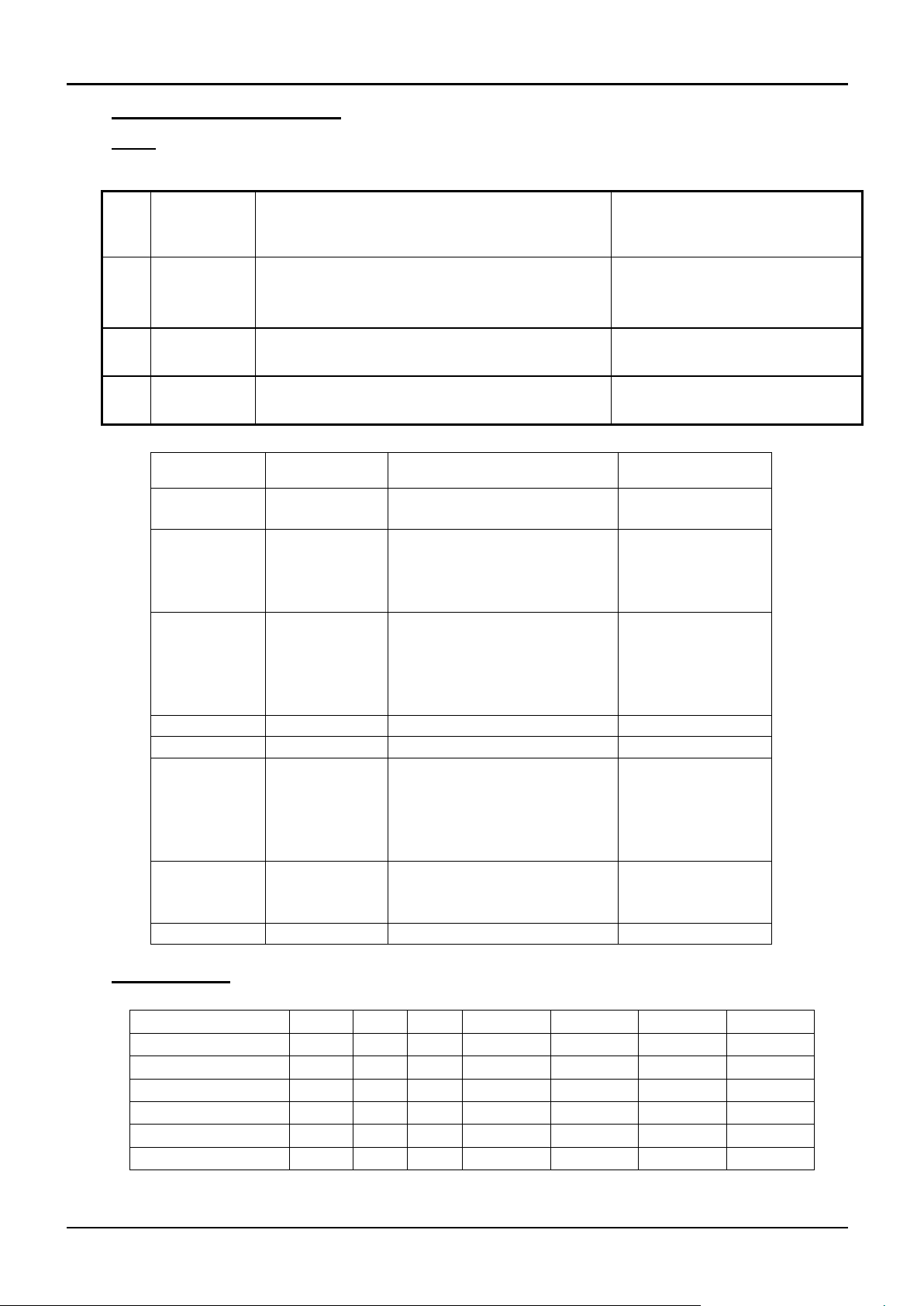
table of the most common fuse ratings is also given in section 8.1 of this manual. Where a supply
cable is present there are internal supply fuses; customer fusing is preferred but not essential.
Furnace with supply cable: either wire directly to an isolator or fitted with a line plug.
Furnace without supply cable: a permanent connection to a fused and isolated supply should be
made to the internal terminals after temporary removal of the furnace back panel.
Connection by line plug: the plug should be within reach of the operator, and should be quickly
removable.
Connection to isolating switch: this should operate on both conductors (single phase) or on both
live conductors (two phase), and should be within reach of the operator.
The supply MUST incorporate an earth (ground).
MF06 3.32 3
Page 4

L3
Black
to phase 3 except 2-phase
N
Light Blue
to neutral except delta
PE
Green/Yellow
to earth (ground)
AAF, GSM, VMF
2.4 “Universal Wiring”
Year 2000: 18 litre 3-phase models only
Year 2001 onwards: 18 litre 1-phase and 3-phase
The AAF 11/18 and 12/18 can be easily rewired between 1-phase and 3-phase supplies. This
applies to 3-phase+N and 3-phase delta in the ranges 380/220V–415/240V and 208-240V, but
does not apply to 3-phase star without neutral (e.g. 380V).
To alter the configuration, remove the back panel and alter the wiring connections between the
supply terminal block and the EMC filters, using the appropriate diagram from section 7.4.
Models made for single phase only (e.g. before year 2001) are not affected and cannot be
converted to 3-phase.
If in doubt, please consult Carbolite.
4 MF06 – 3.32
Page 5

AAF, GSM, VMF
3.0 OPERATION
The instructions for operating the temperature controller are given in a separate manual.
If the furnace is fitted with a time switch, see also the supplementary manual MS03.
If cascade control is fitted, see the supplementary manual MS07.
3.1 Operating Cycle
The furnace is fitted with an instrument switch. The switch cuts off power to the control circuit.
Connect the furnace to the electrical supply.
Operate the instrument switch to activate the temperature controller. The controller becomes
illuminated and goes through a short test cycle.
Close the furnace door and adjust the temperature controller – see the controller manual.
Overtemperature option only. If the overtemperature controller has not yet been set as required,
set it and activate it according to the instructions in the appropriate manual.
Unless a time switch is fitted and is off, the furnace starts to heat up. The Heat light(s) glow
steadily at first and then flash as the furnace approaches the desired temperature or a program
setpoint.
Overtemperature option only. If the overtemperature trip operates then an indicator in the
overtemperature controller flashes, and the heating elements are isolated. Find and correct the
cause before resetting the overtemperature controller according the instructions supplied.
To turn the furnace off, set the Instrument switch to it’s off position; the controller display will go
blank. If the furnace is to be left off unattended, isolate it the electrical supply.
3.2 General Operating Advice
Heating element life is shortened by use at temperatures close to maximum. Do not leave the
furnace at high temperature when not required. The maximum temperature is shown on the
furnace rating label and on the back page of this manual.
When heating large objects, in particular poor conductors, avoid shielding the thermocouple from
the heating elements. The thermocouple is intended to sense the temperature near the heating
element, but if a large object is placed in the chamber it may record the average temperature of the
object and the elements, which can lead to overheating of the elements. Allow large objects to
gain heat at a lower temperature and then reset the controller to a temperature close to the desired
maximum.
When heating materials which produce smoke or fumes, the chimney must be correctly fitted and
unobstructed. Otherwise, soot can accumulate in the chamber and could possibly cause an
electrical breakdown of the heating element.
If the furnace is used to heat materials which emit smoke or fumes, regularly heat it up to
maximum temperature for one hour without load to burn away the soot.
Materials such as case hardening compounds and other reactive salts may penetrate the furnace
chamber lining and attack the wire elements, causing premature failure. Use of a hearth tile may
be advisable: please consult our technical department.
Lightweight ceramic fibre insulation can easily be marked by accidental contact. Some fine cracks
may be visible on the surface of the insulation, or may develop in the surface of the chamber due
to the progressive shrinkage of the insulation materials. Cracks are not usually detrimental to the
functioning or the safety of the furnace.
3.3 Use of Probes
MF06 3.32 5
Page 6

AAF, GSM, VMF
Any metal object used to probe into the furnace chamber while the furnace is
connected to the supply must be earthed (grounded). This applies in particular to
metal sheathed thermocouples, where the sheaths must be earthed. The refractory
material of the chamber lining becomes partly conducting at high temperatures, and
the electric potential inside the chamber can be at any value between zero and the
supply voltage. Unearthed probes can cause serious electric shock.
3.4 Atmospheres
When an optional gas inlet is fitted there is a label near the inlet saying "INERT GAS ONLY". In
practice inert or oxidising gases may be used, but not combustible or toxic gases. Chamber
furnaces are not gas tight, so it should be understood that gas usage may be high, and that the
chamber is likely always to contain some air. Residual oxygen levels of 1% may be expected.
3.5 Operator Safety
The furnace incorporates a safety switch which interrupts the heating element circuit when the
door is opened. This prevents the user touching a live heating element, but also prevents the
furnace from heating up if the door is left open. The operation of this switch should be checked
periodically – see section 4.1.2.
Avoid burns: furnace surfaces can be hot. Before you remove a hot object from the furnace make
sure you have a safe place to put it down.
3.6 Power Adjustment
The furnace control system incorporates electronic power limiting, which is used in some models
to compensate for voltage to achieve the same power over a range of voltage supplies. In other
models the power limit is set to 100% over all common voltages. The power limit parameter OP.Hi
may be accessible to the operator, but should not generally be altered.
See section 8.2 for details of power limit settings. DO NOT adjust the power to a level higher that
the design level stated: this may cause fuse to blow, and could damage the heating elements.
The power limit may be set to a lower limit if the furnace is to be used at a low temperature only:
this may give better control stability. It may set to zero to permit demonstration of the controls
without the heating elements taking power; to resume heating reset it to its standard value.
6 MF06 – 3.32
Page 7

AAF, GSM, VMF
4.0 MAINTENANCE
4.1 General Maintenance
Preventive rather than reactive maintenance is to be preferred. The type and frequency depends on
furnace use: the following are recommended.
4.1.1 Cleaning
Soot deposits may form inside the furnace, depending on the process. At appropriate intervals
remove these by heating as indicated in section 3.2.
The furnace outer surface may be cleaned with a damp cloth. Do not allow water to enter the
interior of the case or chamber. Do not clean with organic solvents.
4.1.2 Safety Switch
The door switch operation mentioned in 3.5 should be checked periodically to ensure that heating
elements are isolated when the door is opened. In normal conditions the safety arrangement should
outlast the furnace, but it could be affected by rough handling, a corrosive environment or work
materials, or exceptional frequency of use.
A qualified electrician should check that the supply to the heating elements is cut, with and
without power being on, when the door is open partially and fully; it is important that isolation is
not just marginally achieved. The check is best made on the element terminals after removal of the
furnace back: probing the element surface inside the furnace could be inconclusive because of
surface oxidation. Note that all live supply wires of a 3-phase supply, and both live and neutral of
a 1-phase supply, should be isolated when the door is opened.
4.2 Calibration
After prolonged use the controller and/or thermocouple could require recalibration. This would be
important for processes which require accurate temperature readings or which use the furnace
close to its maximum temperature. A quick check using an independent thermocouple and
temperature indicator should be made from time to time to determine whether full calibration is
required. Carbolite can supply these items.
Depending on the controller, the controller manual may contain calibration instructions.
4.3 After Sales Service
Carbolite’s service division (Carbolite Engineering Services) has a team of Service Engineers
capable of repair, calibration and preventive maintenance of furnace and oven products at our
customers’ premises throughout the world. We also sell spares by mail order. A telephone call or
fax often enables a fault to be diagnosed and the necessary spare part despatched.
Each furnace has its own record card at Carbolite. In all correspondence please quote the serial
number, model type and voltage given on the rating label of the furnace. The serial number and
model type are also given on the front of this booklet when supplied with a furnace.
To contact Carbolite Engineering Services or Carbolite see the back page of this manual.
4.4 Recommended Spares Kits
Carbolite can supply individual spares, or a kit of the items most likely to be required. Ordering a
kit in advance can save time in the event of a breakdown. Each kit comprises one thermocouple,
one sheath, one solid state relay, one door insulation piece, and one element or set of elements.
Individual spares are also available.
When ordering spares please quote the model details as requested above.
MF06 3.32 7
Page 8
AAF, GSM, VMF
5.0 REPAIRS & REPLACEMENTS
5.1 Safety Warning – Disconnection from Supply
Always ensure that the furnace is disconnected from the supply before repair work
is carried out.
5.2 Safety Note - Refractory Fibrous Insulation
Insulation made from High Temperature Insulation Wool
Refractory Ceramic Fibre, (better described as Alumino Silicate Wool)
(ASW)
This product contains alumino silicate wool products in its thermal insulation.
These materials may be in the form of blanket or felt, formed board or shapes, mineral wool slab
or loose fill wool.
Whilst there is no evidence of any long term health hazards, we strongly recommend that safety
precautions are taken whenever the materials are handled.
Exposure to fibrous dust may cause respiratory disease.
When handling the material always use an approved respiratory protection equipment
(RPE-i.e. FFP3), eye protection, gloves and long sleeved clothing.
Avoid breaking up waste material. Dispose of waste in sealed containers.
After handling rinse exposed skin with water before washing gently with soap (not
detergent). Wash work clothing separately.
Before commencing any major repairs we recommend reference to the European Association
representing the High Temperature Insulation Wool industry (www.ecfia.eu)
We can provide further information on request. Alternatively our service division can quote for
any repairs to be carried out at your premises or ours.
5.3 Temperature Controller Replacement
201. This controller is fitted to the back of the control panel; in many models this can be separated
from the base by removal of two screws.
Before handling the controller: wear an anti-static wrist strap or otherwise avoid any possibility
of damage to the unit by static electricity.
Refer to the detailed instructions supplied with the replacement controller.
2132, 2416, 2408 etc. Ease apart the two lugs at the side; grip the instrument and withdraw it from
its sleeve; push in the replacement.
5.4 Solid-state Relay Replacement
Disconnect the furnace from the supply, and remove the furnace back panel.
Make a note how the wires are connected to the solid state relay, and disconnect them.
Remove the solid state relay from the base panel or aluminium plate.
Replace and reconnect the solid state relay ensuring that the heat-conducting thermal pad is
sandwiched between the relay and the base panel or aluminium plate. Alternatively a thin layer of
white, heat-conducting silicon paste may be applied between the new relay and the plate.
The new solid state relay contains a built-in MOV which protects it from short periods of excess
voltage. If the old relay had a separate disc-shaped "MOV" connected between the high voltage
terminals of the old relay, discard the old MOV.
Replace the removed panel
8 MF06 – 3.32
Page 9
AAF, GSM, VMF
Negative
positive (type K)
White
green
5.5 Thermocouple Replacement
Disconnect the furnace from the supply, and remove the furnace back panel.
Make a note of the thermocouple connections. The negative leg of the thermocouple is marked
blue. Compensating cable colour codings are:
Disconnect the thermocouple from its terminal block.
Bend the metal tag, or release the screw, to release the thermocouple sheath, withdraw the sheath,
and shake out any fragments of thermocouple.
Re-assemble with a new thermocouple observing the colour coding, ensuring that the
thermocouple is not twisted as it is being inserted and that the metal tag is bent back, or the screw
inserted, to grip the sheath.
5.6 Element Replacement (AAF 11/3, AAF 12/3, AAF 11/7, AAF 12/7, GSM)
See section 5.2 - wearing a face mask is recommended.
The chamber of this type of furnace is formed by winding resistance heating wire on to a
refractory muffle former. In the event of failure, the whole "wound muffle" assembly must be
replaced.
Disconnect the furnace from the supply and remove the furnace back panel. GSM: Pull the
chimney out of the top of the furnace.
Make a note of the wiring connections; see the section above which refers to the thermocouple
colour coding.
Unfasten the electrical connections to the inner chamber (brick-box) and remove the thermocouple
and sheath (see thermocouple replacement instructions). If the connections are secured by
hexagonal nuts, two spanners should be used to avoid cracking the porcelain mounting.
Undo any self-tapping screws and hook bolts necessary to release the brick-box.
Support the front of the brick-box as you withdraw it from the case so it does not fall onto the
electrical connections below.
Remove the brick-box lid and top insulating board, noting how it is assembled and observing the
position of the heating element wires (or “tails”).
Pull the element tails out of the terminal block and remove sufficient insulation to allow access to
the heating element. Check and replace damaged insulation.
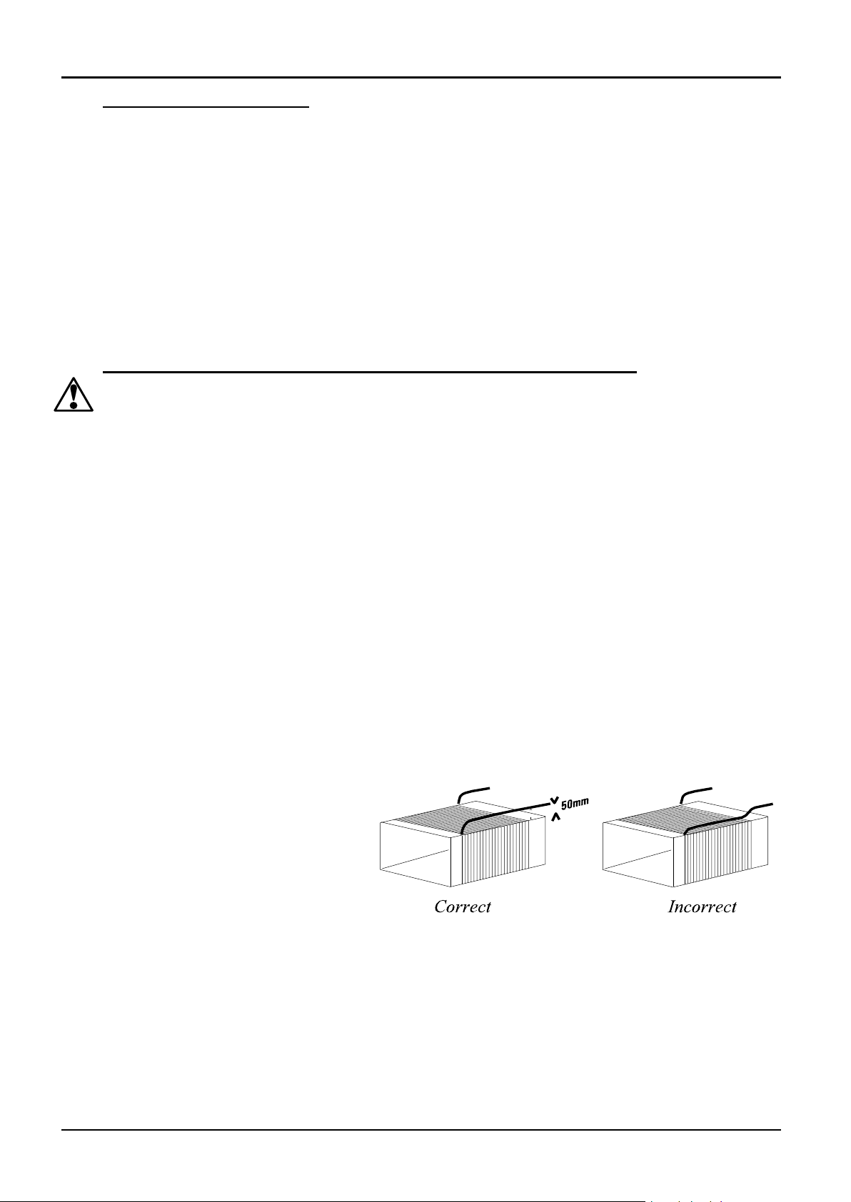
Fit the new heating element,
ensuring that the tails are separated
from the element by at least 25 mm
(preferably 50mm) of insulation –
see the picture.
Feed the element tails through the
terminal blocks and tighten the
clamping screws using two spanners
as before. Cut off excess element tails.
Complete the fitting of the insulation and refit the lid. Do not use any cement unless supplied by
Carbolite, as other types may chemically attack the heating element.
Replace and fasten the brick-box into the furnace case.
Replace the thermocouple and sheath and remake the electrical connections. In porcelain and brass
terminal blocks the brass connector should be slightly loose in its porcelain support block to allow
for expansion.
Replace the back panel and reconnect the electrical supply.
MF06 3.32 9
Page 10
N
AAF 11/18 element connection example
(1-phase 200-240V)
L
N
L
L N link
terminal
block
AAF, GSM, VMF
Switch the furnace ON and heat to 900°C without interruption, and then soak for 1 hour. Some
smoke may be observed during this process, which should be carried out in a well ventilated area.
Check that the furnace is controlling properly to rule out the possibility that previous element
failed because of a fault in the control circuit.
5.7 Panel Element Replacement (AAF 11/18 and 12/18)
See section 5.2 - wearing a face mask is recommended.
The chambers have two side-mounted refractory panels in which coiled heating elements are
inserted, normally out of sight behind silicon carbide chamber walls.
Disconnect the furnace from the supply and remove the furnace back panel.
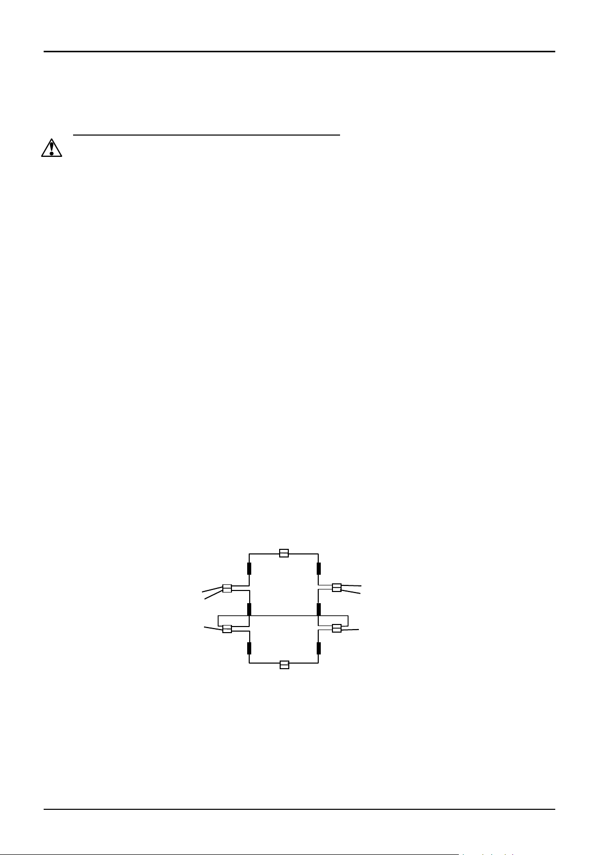
Make a written plan showing ALL the element and thermocouple connections. It is important to
make this plan for each individual furnace.
Disconnect all the element wire tails and thermocouple cables from their terminal blocks.
Straighten all the element tails. Note that these become brittle with use.
Unscrew the screws fixing the metal back piece from the inner chamber and withdraw this part
backwards complete with thermocouple(s) and sheath(s).
Withdraw the back insulation piece. Handle with care. Observe the warning on handling of
ceramic fibrous insulation – section 5.2.
Remove the Silicon Carbide chamber side walls, then withdraw the old element(s), and insert the
new. Note that the ceramic element carriers are in two pieces, front and back: take care when
handling them.
Replace the back insulation piece and metal piece together with the thermocouple(s) and sheath(s).
As necessary, shorten the element tails by clipping to length.
Remake all the thermocouple and element connections according to the individual plan.
Refit the back panel and run the furnace for 30 minutes at 800°C without interruption to ensure
complete burn-off of any organic binders. Some smoke may be observed during this process,
which should be carried out in a well ventilated area.
Check that the furnace is controlling properly to rule out the possibility that previous element
failed because of a fault elsewhere in the control circuit.
10 MF06 – 3.32
Page 11
AAF, GSM, VMF
5.8 VMF 10/6 Element Replacement
See section 5.2 - wearing a face mask is recommended.
The heating elements are vacuum formed modules; they are fragile, so spare elements are supplied
complete in an insulation box to avoid damage.
Disconnect the furnace, remove the back panel, make a plan of all the internal connections to the
back of the heating chamber and disconnect. Remove the thermocouple(s) and support tube(s).
Using a socket spanner undo the four bolts that fasten the insulation box. These are located under
the insulation box in the two cross supports.
Remove the insulation box by carefully sliding it out through the back of the furnace case.
Carefully slide in the new insulation box, and fasten the four bolts. DO NOT support the element
by putting your hand inside the chamber – the element is fragile.
As necessary, shorten the element tails by clipping to length. Remake all the thermocouple and
element connections according to the individual plan.
Refit the back panel and run the furnace for 30 minutes at 800°C without interruption to ensure
complete burn-off of any organic binders, Some smoke may be observed during this process,
which should be carried out in a well ventilated area.
Check that the furnace is controlling properly to rule out the possibility that the previous element
failed because of a fault elsewhere in the control circuit.
5.9 Door Plug Replacement
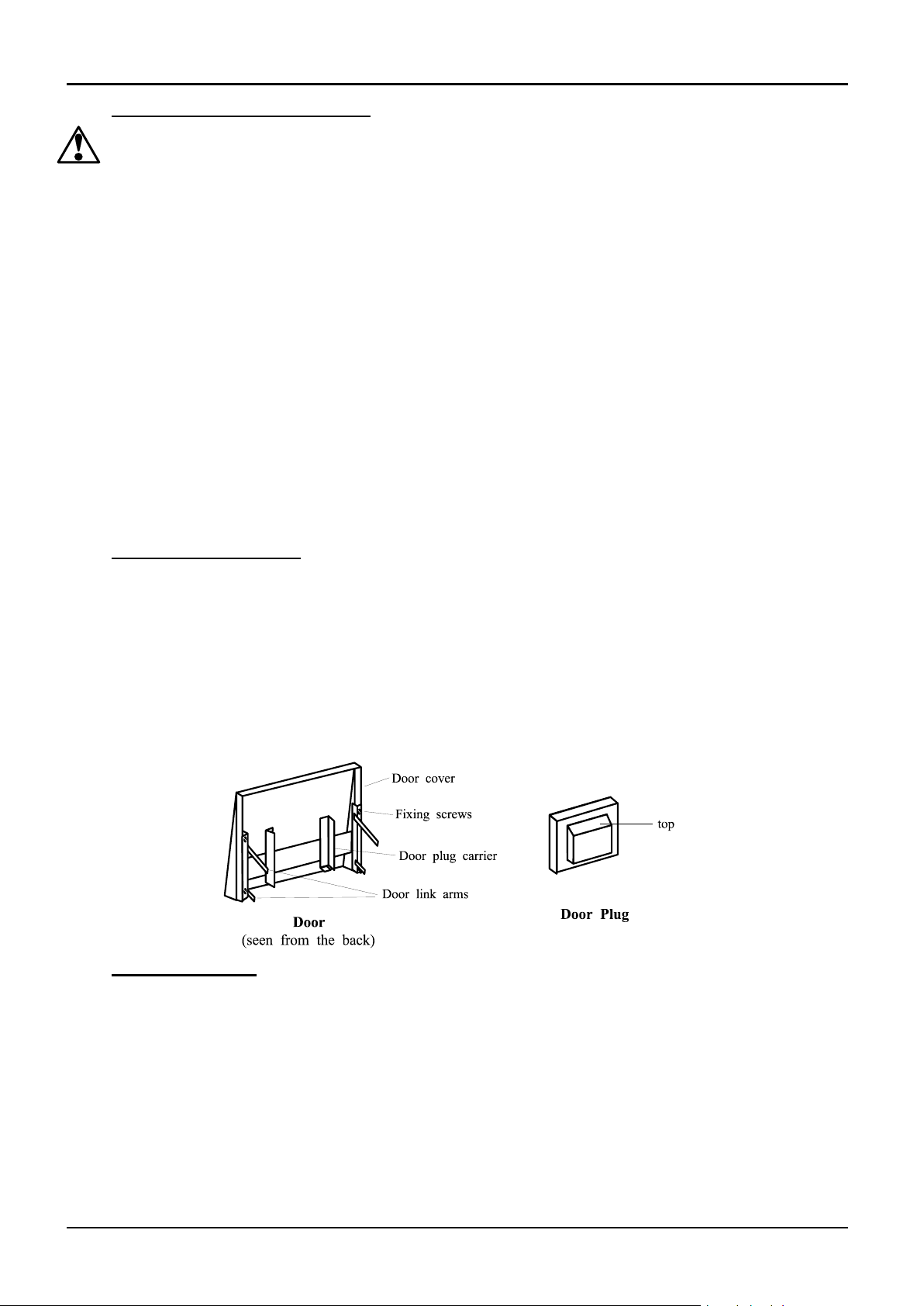
Lift the furnace door to the open position and remove the door cover from the plug carrier
assembly.
Remove the old door plug by sliding it upwards out of its carrier.
Slide the new plug into the carrier assembly making sure that the plug is the correct way up.
Refit the door cover.
When first heating the furnace after a replacement, ensure that the ventilation is good: emission of
some fumes may be expected.
5.10 Fuse Replacement
Fuses are marked on the circuit diagram (section 7.0) with type codes, e.g. F1, F2. A list of the
correct fuses is given in section 8.1. Depending on model and voltage, the different fuse types may
or may not be fitted.
If any fuse has failed, it is advisable for an electrician to check the internal circuits.
Replace any failed fuses with the correct type. For safety reasons do not fit larger capacity fuses
without first consulting Carbolite.
The fuses are near the cable entry point, and access is by removal of the back panel.
MF06 3.32 11
Page 12

A.
Furnace Does Not Heat Up
1.
The HEAT light
is ON
The heating
element has failed
Check also that the SSR is working
correctly
2.
The HEAT light
is OFF
The controller
shows a very high
temperature or a
code such as S.br
The thermocouple has broken or has a
wiring fault
The controller
shows a low
temperature
The door switch(es) (if fitted) may be
faulty or need adjustment
The contactor (if fitted) may be faulty
The SSR could be failing to switch on due
to internal failure, faulty logic wiring from
the controller, or faulty controller
There are no lights
glowing on the
controller
Check the supply fuses and any fuses in the
furnace control compartment
The controller may be faulty or not
receiving a supply due to a faulty switch or
a wiring fault
B.
Furnace Overheats
1.
The HEAT light
goes OFF with
the instrument
switch
The controller
shows a very high
temperature
The controller is faulty
The controller
shows a low
temperature
The thermocouple may have been shorted
out or may have been moved out of the
heating chamber
The thermocouple may be mounted the
wrong way round
The controller may be faulty
2.
The HEAT light
does not go off
with the
instrument
switch
The SSR has failed
“ON”
Check for an accidental wiring fault which
could have overloaded the SSR
AAF, GSM, VMF
6.0 FAULT ANALYSIS
12 MF06 – 3.32
Page 13
AAF, GSM, VMF
F1
N
F2
L1
PE
transformer
Filter (if fitted)
F2
Instrument Switch
for AAF 11/18 see diagram 7.4
Instrument Switch
coil
temperature
controller
overtemp.
controller
door
switch
SSR
e
l
e
m
e
n
t
(s)
heat
on
F3
F1
F2
F3
L
PE
Filter (if fitted)
contactor
or relay
if fitted
thermocouple
thermocouple
e
l
e
m
e
n
t
(s)
e
l
e
m
e
n
t
(s)
F1
N
L2
F2
L1
PE
Instrument Switch
coil
temperature
controller
overtemp.
controller
door
switch
SSR
heat
on
F3
SSR
heat
on
F3
Filter (if fitted)
if fitted
thermocouple
thermocouple
contactor
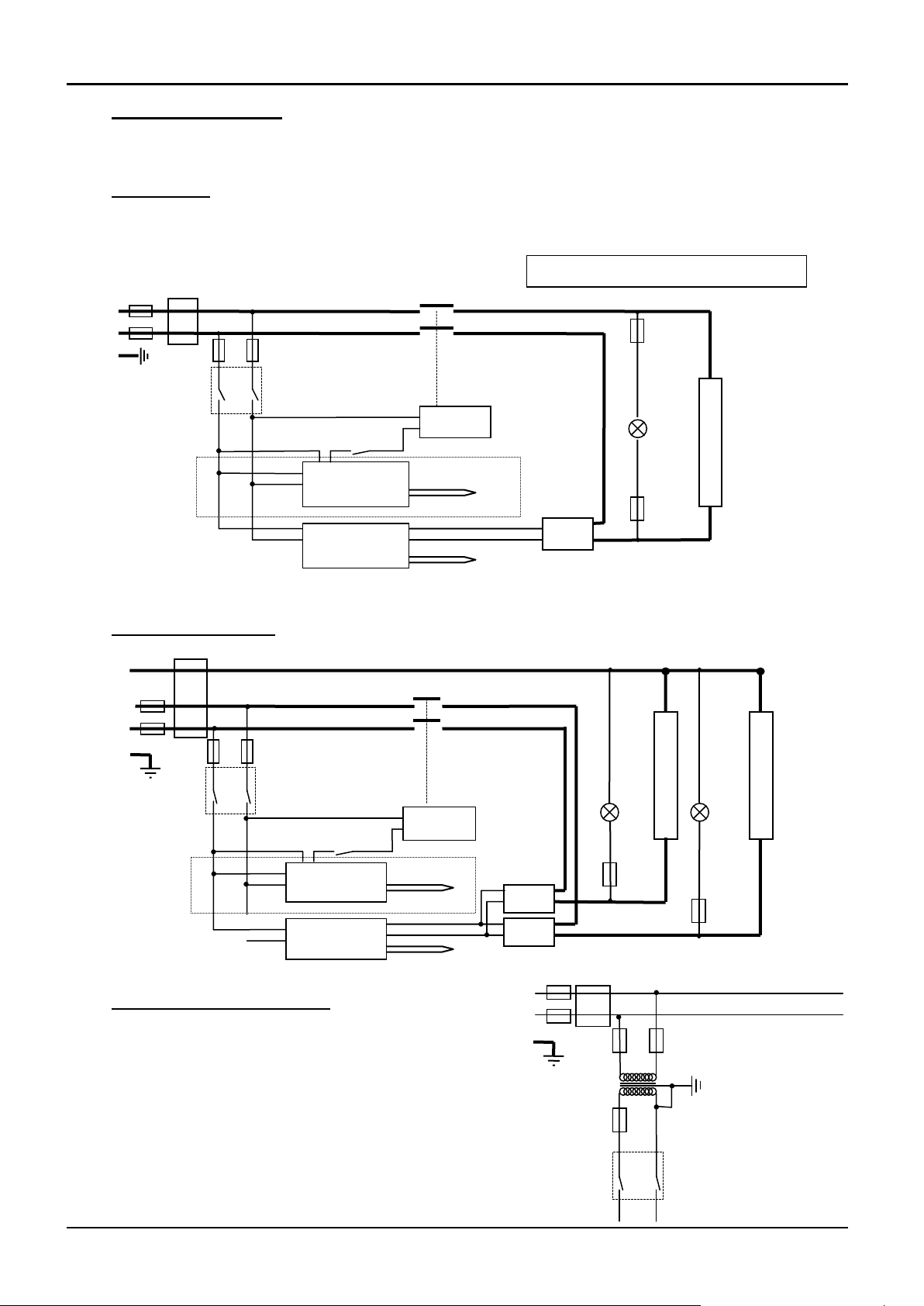
7.0 CIRCUIT DIAGRAMS
EMC Filters (if fitted): dependent on the model there may be one filter, or more than one fitted in
parallel. The circuit diagram examples do not show multiple filter arrangements.
7.1 Single phase
NOTE – models before mid-2002: in some models two door switches were fitted directly in the
element circuit, instead of a single switch and contactor.
7.2 2-phase with neutral
7.3 Higher Voltages (e.g. 254V)
For single phase models of 254V or above, a control
circuit transformer is included as follows:
MF06 3.32 13
Page 14
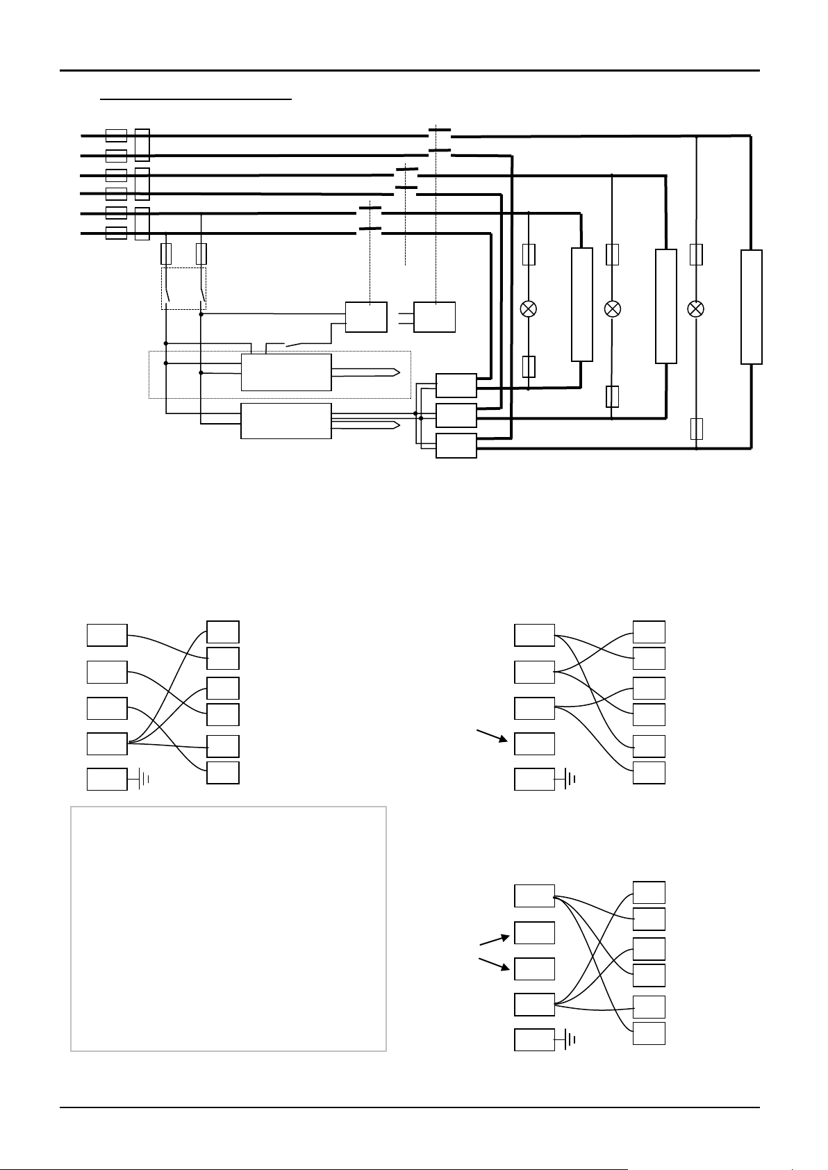
A model made to this diagram can be
converted by the customer between the
following supply voltages:
between 3-phase + neutral in the range
380/220V – 415/240V
and 3-phase delta in the range
220V – 240V
and single phase in the range
220V – 240V
208V model: convertable from 208V delta
to 208V 1-phase
3-phase + neutral
Circuit no. 1
N L N
L
Circuit no. 2
Circuit no. 3
N
L3
L2
L1
Supply
Terminals
N
L
Fuses or
EMC filters
PE
Not
used
3-phase delta
Circuit no. 1
N L N
L
Circuit no. 2
Circuit no. 3
N
L3
L2
L1
Supply
Terminals
N
L
Fuses or
EMC filters
PE
1-phase
Circuit no. 1
N L N
L
Circuit no. 2
Circuit no. 3
N
L3
L2
L1
Supply
Terminals
N
L
Fuses or
EMC filters
PE
Not
used
Applies only to AAF 11/18
Instrument Switch
coil
temperature
controller
overtemp.
controller
thermocouple
door
switch
SSR
heat
on
F3
F1
F2
F3
SSR
SSR
F3
heat
on
F3
e
l
e
m
e
n
t
(s)
heat
on
F3
F3
if fitted
Contactors
(2 or 3)
Filters (if fitted)
e
l
e
m
e
n
t
(s)
e
l
e
m
e
n
t
(s)
coil
L N L N L
N
thermocouple
AAF, GSM, VMF
7.4 3-phase “universal” wiring
Fuses F1 are always present in this wiring design.
Fuses F2 could be absent in some circumstances, if the circuit does not exceed 10A.
Fuses F3 are present if the circuit exceeds 25A, but otherwise are usually absent.
14 MF06 – 3.32
Page 15
F1
Internal
supply
fuses
Fitted if supply cable fitted.
Fitted on board to some types of EMC filter.
on-board and up to 16 Amps:
32mm x 6mm type F
other: GEC Safeclip
F2
Auxiliary
circuit
fuses
Fitted on board to some types of EMC filter.
May be omitted up to 25Amp/phase supply
rating.
2 Amps glass type F
On board: 20mm x 5mm
Other: 32mm x 6mm
F3
Heat Light
fuses
May be omitted up to 25 Amp/phase supply
rating.
2 Amps glass type F
32mm x 6mm
Customer
fuses
Required if no supply cable fitted.
Recommended if cable fitted.
See rating label for amperage;
see table below for fuse rating.
Model
Phases
Volts
Supply Fuse
rating
AAF 11/3
1-phase
200-240
10A 1-phase
110
20A
AAF 11/7
1-phase
1-phase
1-phase
2-phase+N
220-240
200-208
110-120
380/220-415/240
20A
20A
40A
10A per phase
AAF 11/18
1-phase
220-240
30A 1-phase
200-208
40A 3-phase+N
380/220-415/240
12.5A per phase
3-phase delta
220-240
20A per phase
3-phase delta
200-208
25A per phase
AAF 12/3
1 phase
200 - 240
10A
AAF 12/7
1-phase
220–240
25A
AAF 12/18
1-phase
220-240
30A 1-phase
200-208
40A 3-phase+N
380/220-415/240
12.5A per phase
3-phase delta
220-240
20A per phase
3-phase delta
200-208
25A per phase
GSM 11/8
1-phase
1-phase
1-phase
220-240
200-208
110-120
12.5A
15A or 16A
25A
VMF 10/6
1-phase
220-240
12.5A
model volts:
110
200
208
220, 380
230, 400
240, 415
254, 440
AAF 11/3
87
100
98
87
80
73
65
AAF 11/18
100
100
100
100
94
83
AAF 12/3
100
95
85
78
71
AAF 12/7
100
100
100
AAF 12/18
100
100
100
100
94
83
all other models
100
100
100
100
100
89
8.0 FUSES & POWER SETTINGS
8.1 Fuses
F1-F3: Refer to the circuit diagrams.
AAF, GSM, VMF
8.2 Power Settings
The settings of the power limit parameter OP.Hi are as follows.
MF06 3.32 15
Page 16
Carbolite, Parsons Lane, Hope,
Hope Valley, S33 6RB, England.
Telephone: +44 (0)1433 620011
Fax: +44 (0)1433 621198
E-mail: [email protected]
The products covered in this manual are only a small part of the wide range of
ovens, chamber furnaces and tube furnaces manufactured by Carbolite for
laboratory and industrial use. For further details of our standard or custom built
products please contact us at the address below, or ask your nearest stockist.
Copyright © 2014 Carbolite Limited
For preventive maintenance, repair and calibration of all Furnace
and Oven products, please contact:
Carbolite Engineering Services
MF06 – 3.32 14/08/14
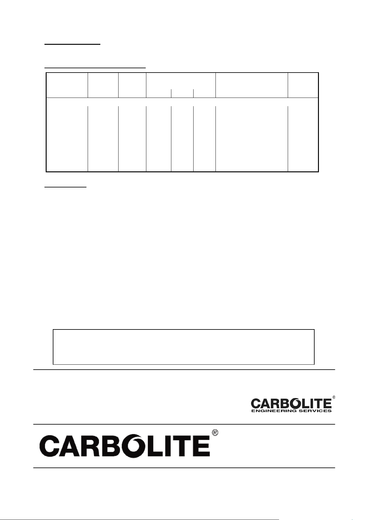
9.0 SPECIFICATIONS
MODEL
Max.
Temp.
Max.
Power
Chamber Size (mm)
Heating Elements
Net
Weight
(°C)
(kW)
H W D
(l)
(kg)
Ashing, Burn-off and Coal & Coke Testing Furnaces
AAF 11/3
1100°C
2.1
85
150
250
Wound muffle
22
AAF 11/7
1100°C
3.9
90
170
445
Wound muffle
63
AAF 11/18
1100°C
7
235
196
400
Concealed wire
70
AAF 12/3
1200°C
2
85
150
250
Wound Muffle
22
AAF 12/7
1200°C
6
90
170
445
Wound Muffle
63
AAF 12/18
1200°C
7
235
196
400
Concealed wire
70
GSM 11/8
1100°C
3.0
125
185
345
Wound silica muffle
63
VMF 10/6
1000°C
3.0
100
210
260
Vacuum formed slabs
45
temperature:
5°C - 40°C
relative humidity:
maximum 80% up to 31°C decreasing linearly to 50% at 40°C
Carbolite reserves the right to change specifications without notice.
9.1 Models Covered by this Manual
9.2 Environment
The furnaces contain electrical parts and should be stored and used in indoor conditions as
follows:
 Loading...