

Carbolite Type 301 Operating Instructions Manual
MC16-EN – 1.04
Operating Instructions
Temperature Controller
T
yp
e 301
English / °C

Introduction
2
MC16-EN – 1.04
Contents
Section Title Page
1 Introduction to the Controller and Manual 4
1.1
Using This Manual
4
1.2
PID Control
4
1.3
Key Stroke Diagrams
4
2 Basic Operation 5
2.1
Keys
5
2.2
Indicators
5
2.3
Menu System
5
2.4
Home display
6
2.5
Hold Mode
6
2.6
Checking the Temperature Setpoint from the Home display
7
2.7
Changing the Temperature Setpoint
7
2.8
Changing the Temperature Setpoint Ramp Rate
7
2.9
Changing the Timer Time
7
3 Advanced Operation 8
3.1
Entering the Set Up menu
8
3.2
Changing the Timer Type
8
3.3
Changing the Timer Band
8
3.4
Changing the Maximum Output Power
9
3.5
Changing the Customer Calibration Type
9
3.6
Calibration Password
9
4 Temperature Setpoint Ramp Rate 10
4.1
Setpoint Ramp Rate
10
4.2
Limitations of setpoint Ramp Rate
10
5 The Timer 10
5.1
Starting the Timer
10
5.3
Pausing The Timer
10
5.4
Resetting The Timer
11
5.5
Timer Function Description
11
5.6
The Timer Temperature Band
11
5.7
Timer Function Table
12
6 Ramp Dwell 13
6.1
Setting up a Ramp Dwell program
13
7 Maximum Output Setting 15
8 Customer Calibration 15
8.1
Factory Calibration - FAct
15
8.2
Single Point Calibration - C.CL1
15
8.3
Dual Point Calibration - C.CL2
16
8.4
Changing the Calibration, Low Temperature – CAL.L
16
8.5
Changing the Calibration, Low Temperature Offset - OFS.L
17
8.6
Changing the Calibration, High Temperature – CAL.H
17
8.7
Changing the Calibration, High Temperature Offset - OFS.H
17

Contents
3
MC16-EN– 1.04
9 Overtemperature protection 18
9.1
Overtemperature (O/T) Home Display
18
9.2
Changing the Overtemperature Limit
19
9.3
Checking the Overtemperature sensor temperature
19
9.4
Overtemperature Protection Calibration
19
9.5
Overtemperature Activation
20
9.6
Resetting Overtemperature Activation
20
10 RS232 Communication 20
10.1 RS232 Communication Addressing: 20
10.2 RS232 Communication Cables 21
11 Navigation Diagrams 21
12 Controller Fault 22
12.1
Fault Code Diagnostic Table
22
13 Glossary of Terms 22
Introduction
4
MC16-EN – 1.04
1 Introduction to the Controller and Manual
1.1 Using This Manual
This manual aims to explain how to set up and operate the 301 controller; it must be read in
conjunction with the product main manual.
Due to the complex nature of furnace or oven control the use of technical terms throughout
this manual is unavoidable. Explanations of these terms can be found in the ‘Glossary of
Terms’ at the back of this manual.
1.2 PID Control
The 301 controller uses PID (Proportional Integral Derivative) temperature control. This
type of control uses a complex mathematical control system to adjust the power being sent
to the elements and hold the furnace or oven at the desired temperature.
1.3 Key Stroke Diagrams
Throughout this manual, key stoke diagrams are used to quickly describe the key presses
required on the controller to alter the desired value.
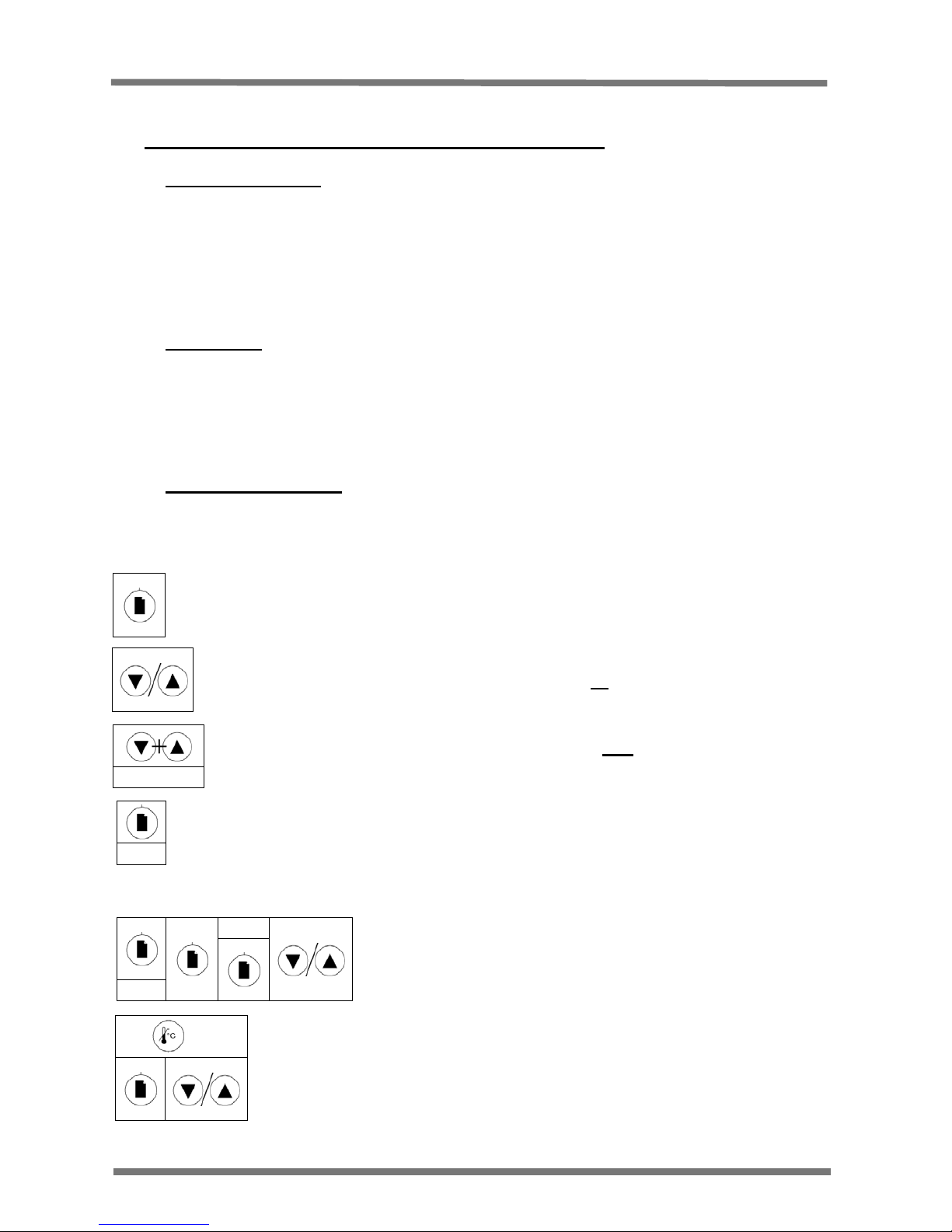
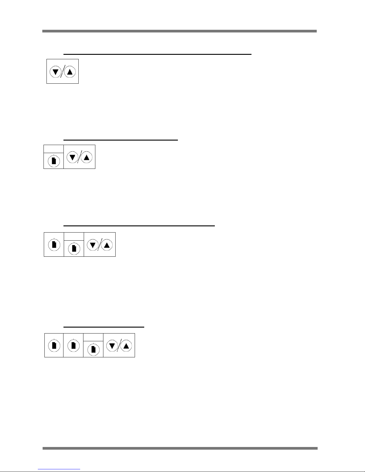
Examples of key press sequences:
This symbol denotes a single press of the Page Key
This symbol denotes a single press of the Up Key or the Down Key
This symbol denotes pressing and holding the Page key for 1.5 seconds
Hold
This symbol denotes a single press of the Up Key and the Down Key for 1.5
Secs
Hold Together
Hold
These symbols denote holding the Overtemperature key down
while pressing the Page key, followed by the Up or Down arrow
key.
OPHi
These symbols denote holding the Page key for
1.5 seconds, pressing the Page key twice (OPHi
should be showing on the display) then pressing
the Up or Down arrow key.
Hold
Basic Operation
5
MC16-EN – 1.02
2 Basic Operation
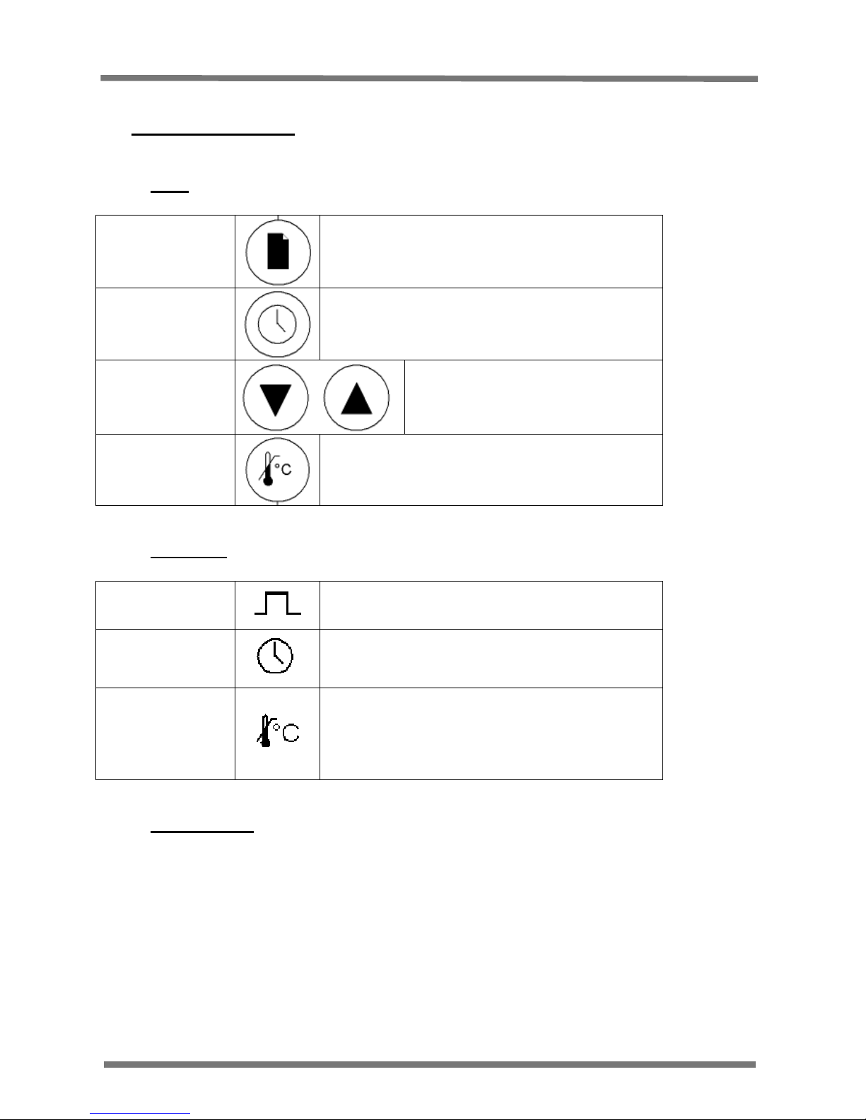
2.1 Keys
Page Key
The Page key is used to scroll through the
parameters and switch between menus.
Timer Key
The Timer key is used to start, view, pause
and reset the timer.
Arrow Keys
The Arrow keys are used to adjust
the value of the selected
parameter and pause the output
power.
Overtemperature
Key
The Overtemperature key is used to access
the Overtemperature menu.
Note: Overtemperature is an option
2.2 Indicators
Output Indicator
The Output indicator shows when the
controller is sending power to the elements.
Timer Indicator
The Timer indicator shows when the timer is
active.
Overtemperature
Indicator
The Overtemperature indicator shows green
in normal use. It flashes red when
overtemperature is triggered and is constantly
red when overtemperature is reset and waiting
for the temperature to drop.
2.3 Menu System
The 301 controller is divided into two menus; the home menu and the set up menu. The
home menu contains all the basic operating controls: setpoint, setpoint ramp rate and timer
time. The set up menu contains all the set up features: timer type, timer band, output power
and customer calibration. The features available vary depending on user input or product
specification.
Basic Operation
6
MC16-EN – 1.04
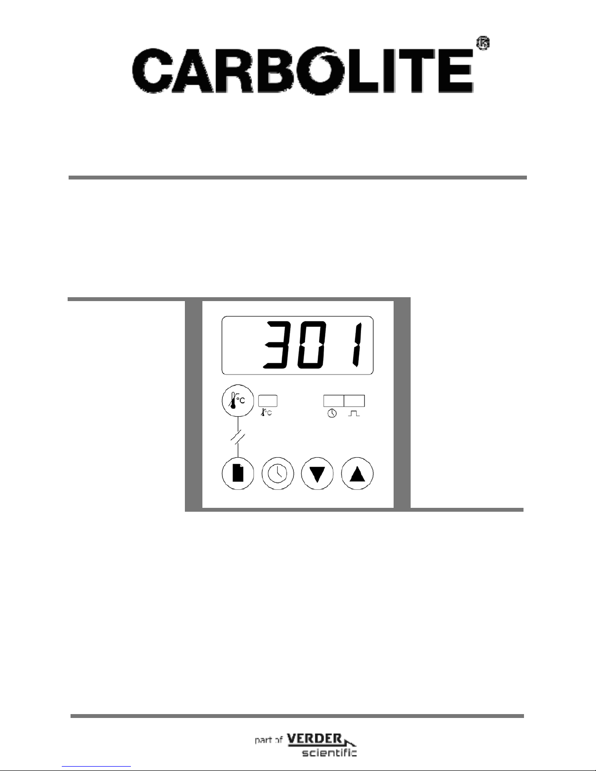
2.4 Home display
The Home display is the first display you see when the controller is switched on. It shows
the actual temperature of the furnace or oven and will be referred to as PV throughout this
manual. If you enter the menus, the controller will automatically return to the Home display
if no keys are pressed for 30 seconds.
2.4.1 Finding the Home display from the Home menu
Press the Page key until the PV is shown on the display (301 shown as example).
2.4.2 Finding the Home screen from the Set up menu
Press and hold the Page key for 1.5 seconds
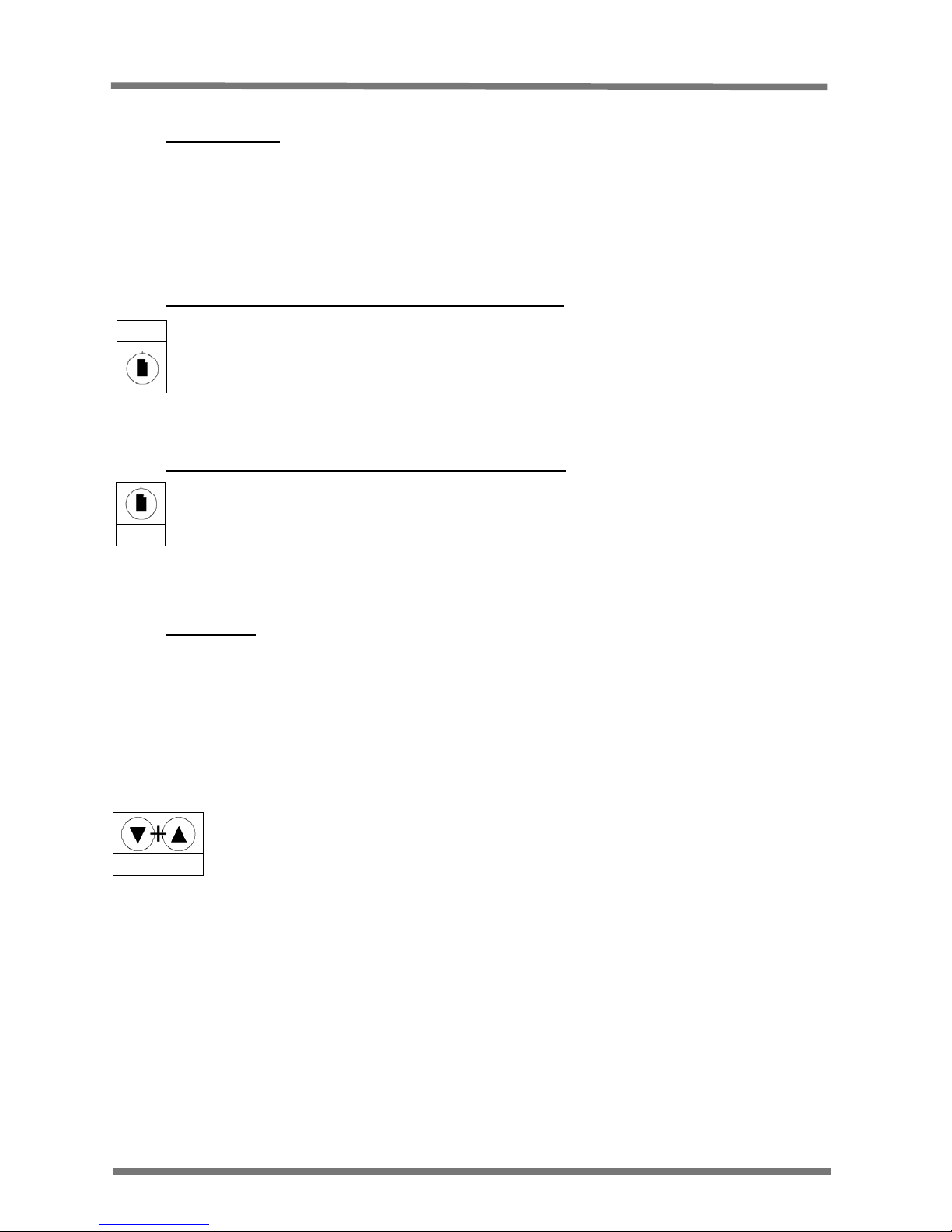
2.5 Hold Mode
Hold mode turns the output off; this allows for parameters to be set without the controller
instantly trying to control at the new settings.
Hold mode is shown on the display by the output indicator being off and the home display
flashing between the PV and HOLd.
To enter Hold mode:
Start at the Home display
Press and hold the Up and Down arrow keys together for 1.5 seconds.
The display will flash HOLd to show that hold mode has been entered.
To exit Hold Mode:
Start at the Home display.
Press and hold the Up and Down arrow keys together for 1.5 seconds OR start the timer
(See section 5).
Note: The Hold Mode function is disabled when the Timer function is running.
Hold Together
301
Hold
Basic Operation
7
MC16-EN– 1.04
2.6 Checking the Temperature Setpoint from the Home display
Start at the Home display
Press an Up or Down arrow key.
The display will then flash SP%C 3 times.
The Setpoint will show on the display for 3 seconds before returning to the Home display.
2.7 Changing the Temperature Setpoint
Start at the Home display
Press the Page key to scroll through the home menu until SP%C shows on the display
Use the Up and Down arrow keys to alter the value (°C) – a single press shows the current
setting, To alter, either keep pressed or press again.
The value will then be stored without any further input.
2.8 Changing the Temperature Setpoint Ramp Rate
Start at the Home display.
Press the Page key to scroll through the home menu until SPrr shows on the display.
Use the Up and Down arrow keys to switch off or alter the value (°C/min) – a single press
shows the current setting. To alter, either keep pressed or press again.
The value will then be stored without any further input.
See section 4 for more information on Temperature Setpoint Ramp Rate.
2.9 Changing the Timer Time
Start at the Home display.
Press the Page key to scroll through the home menu until T1, t2, t3, t4 or t5 shows on the
display.
Use the Up and Down arrow keys either to switch off or alter the value (Hr:Min) – a single
press shows the current setting. To alter either keep pressed or press again.
The value will then be stored without any further input.
See section 5 for more information on The Timer.
T1
SPrr
SP%C
Advanced Operation
8
MC16-EN – 1.04
3 Advanced Operation
3.1 Entering the Set Up menu
Start at the Home display.
Press and hold the Page key for 1.5 seconds
The display will change to the first parameter in the set up menu.
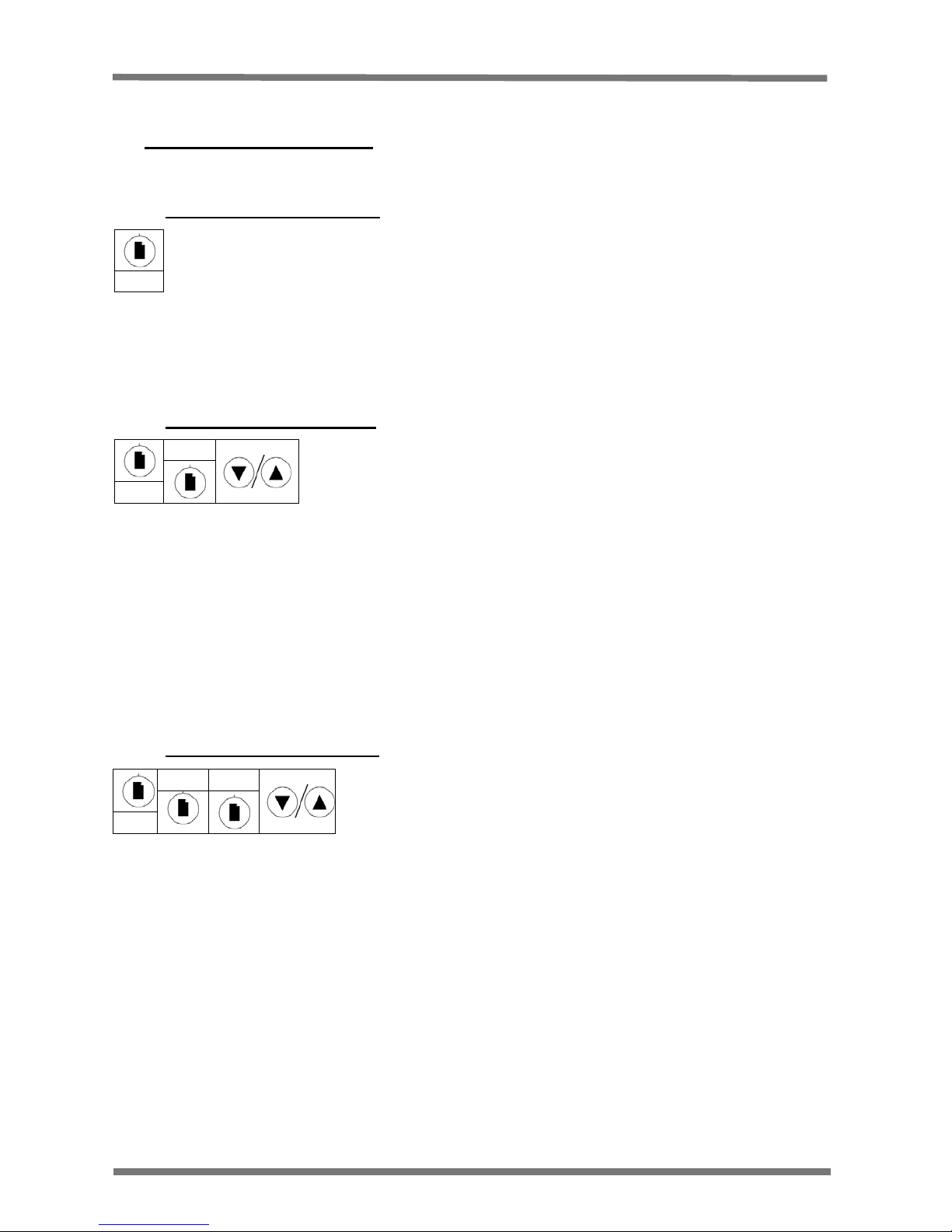
3.2 Changing the Timer Type
Start at the Home display.
Press and hold the Page key for 1.5 seconds to enter the set up menu.
Press the Page key until t.tYP shows on the display.
Use the Up and Down arrow keys to alter the value (t1 to t5) – See section 5. – a single
press shows the current setting, To alter, either keep pressed or press again.
The value will then be stored without any further input.
Note: This function is disabled when the timer is running.
See section 5.5 and 5.7 for more information on the timer types and functions.
3.3 Changing the Timer Band
Note: This is only available when timer type 1 or 4 is selected.
Start at the Home display.
Press and hold the Page key for 1.5 seconds to enter the set up menu.
Press the Page key until t.bnd shows on the display.
Use the Up and Down arrow keys either to turn off or alter the value – a single press shows
the current setting, To alter, either keep pressed or press again.
The value will then be stored without any further input.
See section 5.6 for more information on The Timer Temperature Band.
Hold
t.tYP
Hold
t.tYP tbnd
Hold
 Loading...