


Carbolite MTT 12/38/850 User Manual

CONTENTS
Section page
Operating & Maintenance
Instructions
“MTT 12/38/850”
Combustion Tube Furnace
for Carbon-14 & Tritium Analysis
This manual covers the operation of the furnace only.
See also the Process Manual.
This manual should supply all the information required for safe and trouble-
free furnace operation. Information on controller operation is included.
MF38 – 3.07

Instrument switch: when the instrument switch is operated the temperature
control circuit is energised.
Heat Light: the adjacent light glows or flashes to indicate that power is
being supplied to the elements
DANGER of electrical shock– read any warning printed by this symbol.
DANGER – hot surface. Read any warning printed by this symbol.
WARNING: all surfaces of a furnace may be hot.
DANGER – read any warning printed by this symbol.
Heat Switch: the switch disconnects power to the heating elements; unless
this switch is off there is a danger of electric shock when inserting objects
into the furnace
MTT
1.0 SYMBOLS & WARNINGS
1.1 Switches and Lights
1.2 Warning Symbols
2 MF38 – 3.07

MTT
CONNECTION DETAILS
supply type
Supply
Terminal label
Cable colour
Live-Neutral
Reversible or Live-Live
1-phase
L
Brown
To live
to either power conductor
N
Blue
To neutral
to the other power conductor
PE
Green/Yellow
To earth (ground)
to earth (ground)
2.0 INSTALLATION
2.1 Unpacking & Handling
When unpacking or moving the furnace always lift it by its base or by both ends of the main body.
Never lift it by its work tube or the surrounding insulation. Use two people to carry the furnace.
Remove any packing material before use.
Place the furnace in a well ventilated room, away from other sources of heat, and on a surface
which is resistant to accidental spillage of hot materials. Do not mount the furnace on an
inflammable surface.
Ensure that there is free space around the furnace. Do not obstruct any of the vents in the control
section: they are needed to keep the controls cool.
Ensure that the furnace is placed in such a way that it can be quickly switched off or disconnected
from the electrical supply - see below.
NOTE: This product contains Refractory Ceramic Fibre (better described as Alumino Silicate
Wool) for precautions and advice in handling this material see the ‘Repairs and Replacements’
section.
2.2 Electrical Connections
Connection by a qualified electrician is recommended.
The furnace is supplied for use on a single phase A.C. supply, normally 220-240V. The supply
may be Live to Neutral non-reversible, Live to Neutral reversible or Live to Live. Check the
furnace rating label before connection.
220-240V model: the supply should be fused at 13A or 16A. Internal fuses of 12.5A are fitted. See
section 7.2.
The furnace should either be connected directly to an isolator which operates on both conductors,
or be fitted with a line plug. An isolator should be within easy reach of the operator; a line plug
should be quickly removable.
The supply must incorporate an earth (ground).
MF38 – 3.07 3
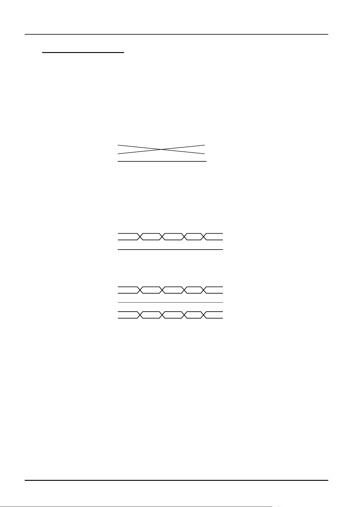
Furnace end of cable
RS232 Cable: furnace to PC
Computer end of cable
female 25-pin (9-pin)
9-pin (25-pin) male
Tx
2 (3)
3 (2)
Tx
Rx
3 (2)
2 (3)
Rx
Com
7 (5)
5 (7)
Com
7,8 (4,5)
Link together
1,4,6 (6,8,20)
Link together
RS485 cable: furnace to furnace
female 25-pin (9-pin)
25-pin (9-pin) female
2 (3)
2 (3)
+
3 (2)
3 (2)
+
Com
7 (5)
7 (5)
Com
RS422: furnace to furnace
female 25-pin
25-pin female
Rx+
3
3
Rx+
Rx
16
16
Rx
Com
7
7
Com
Tx+
12
12
Tx+
Tx
13
13
Tx
MTT
2.3 Connection to a Computer
This furnace is normally fitted with RS485 3-wire communications on the main controller only.
For information, RS232 and 5-wire connections are also shown below. This section does not apply
if the digital communication facility is not fitted.
If the RS232 option is supplied, then the furnace is fitted with one subminiature D-socket
connected to the controller comms module. RS232 is suitable for direct connection to a personal
computer (PC), using a “cross-over” cable as follows (the linked pins at the computer end are
recommended but may not be necessary). The cable is usually 25-pin at the furnace end and 9-pin
at the computer, but other alternatives are shown in parentheses.
If an RS485/422 option is supplied, then the furnace is fitted with two D-sockets. Connection
between products is by “straight” cable as follows:
If a boxed KD485 RS485/422 to RS232 converter is supplied, then the connection cable from
furnace to KD485 should be a “straight” cable, the same as the furnace-to-furnace cable. The
connection between the KD485 and the PC should be a “crossover” cable, the same as the Furnace
to PC cable. Note that the internal wiring of the KD485 box for the 5-wire (RS422) system
includes a cross-over.
4 MF38 – 3.07
MTT
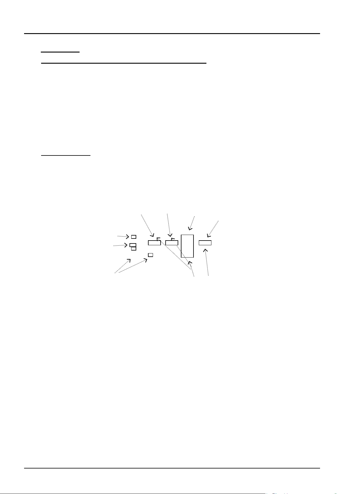
heat lights
instrument switch
Controllers
heater switch
Zone 2
overtemp
Zone 1
overtemp
Zone 2
catalyst
Zone 1
control
3.0 OPERATION
3.1 “MTT 12/38/850” – two zone combustion tube furnace.
The furnace is based on the Carbolite model MTF 12/38/400, but has two independent zones,
giving twice the heated length in total. The two zones are wound on a single ceramic tube (38/46 x
900mm long); each zone is approximately 400mm length. The zones are separated by
approximately 10mm because of the requirement for separate overtemperature systems.
The extended control box type CBT is used for the base.
The zones are independently controlled. Each has independent overtemperature which acts only on
its own zone.
This manual only describes furnace operation. For all other details about the use of this furnace as
a special model for Carbon-14 & Tritium analysis see the separate process Instructions.
3.2 Operating Cycle
The furnace is fitted with an instrument switch. The switch cuts off power to the controllers and
also to the heating elements via a contactor. There is also a Heater switch which can be used to
disconnect power to the elements without switching off the controllers. Heat lights indicated when
controlled power is being supplied to the elements. The instrument layout is as follows:
Operate the instrument switch to activate the temperature controller. The controller becomes
illuminated and goes through a short test cycle.
Set the temperature controllers to the desired setpoint or program - see the supplementary
controller manual.
If the overtemperature controllers have not yet been set as required, set them and activate them
according to the instructions in the supplementary manual for the overtemperature controller.
Switch on the Heater switch, located on the instrument panel. The furnace starts to heat up. The
Heat lights glow steadily at first and then flash as the heating zones approach the desired
temperature or a program setpoint.
If an overtemperature trip operates then an indicator in the overtemperature controller flashes, and
the corresponding heating element is isolated. Find and correct the cause before resetting the
overtemperature controller according the instructions in the supplementary manual.
To switch off power to the heating elements, use the Heater Switch. To switch the furnace off, use
both the Heater switch and the Instrument switch. If the furnace is to be left off unattended, isolate
it from the electrical supply.
MF38 – 3.07 5