

Page 1

Installation, Operation &
p
Maintenance Instructions
900°C Tube Furnace
type MTF 9/15
This manual is for the guidance of operators of the above Carbolite product and
should be read before the furnace is connected to the electricity supply.
1.0
CONTENTS
section page
1.0 Symbols & Warnings 2
2.0 Installation 3
3.0 Operating Instructions 4
4.0 Controller Operation 5
5.0 Maintenance 10
6.0 Repairs & Replacements 11
7.0 Fault Analysis 13
8.0 Circuit Diagram 14
9.0 Fuses & Power Control 15
10.0 S
This manual should supply all the information required for safe and trouble-
free furnace operation. Information on controller operation is included.
ecifications 16
MF09
Page 2
MTF 9/15
SYMBOLS & WARNINGS
1.1 Switches and Lights
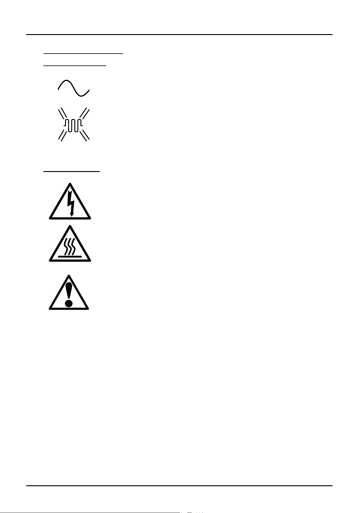
Supply Light: when the furnace is connected to the electrical supply the
light in the adjacent switch glows
1.2 Warning Symbols
Heat Light: the adjacent light glows or flashes to indicate that power is
being supplied to the elements
DANGER of electrical shock– read any warning printed by this symbol.
DANGER – hot surface. Read any warning printed by this symbol.
WARNING: all surfaces of a furnace may be hot.
DANGER – read any warning printed by this symbol.
2.0
2 MF09
Page 3
MTF 9/15
INSTALLATION
2.1 Unpacking & Setting Up
Unpack the furnace carefully and remove any packing from inside the tube.
Place the furnace in a well ventilated area, away from other sources of heat, on a surface which is
resistant to accidental spillage of hot materials. Do not use the furnace on an inflammable surface.
Ensure that there is free space around the furnace. Do not obstruct any of the vents: they are
needed to keep the controls cool.
Ensure that the furnace is placed in such a way that it can be quickly switched off or disconnected
from the electrical supply - see below.
Electrical Connections
2.2
The furnace requires a single-phase A.C. supply with earth (ground). The supply may be Live to
Neutral non-reversible, Live to Neutral with reversible plug, or Live to Live.
The voltage or range of voltages on which the furnace may be operated is given on the furnace
rating label. Check that the supply voltage is compatible with the voltage on the label.
The supply should be fused at not more than 10 Amps, preferably 2 Amps.
The furnace is fitted with a supply cable which may be wired directly to an isolator which operates
on both conductors, or fitted with a line plug which may be quickly disconnected from the supply.
The supply MUST incorporate an earth (ground).
Connect the supply as follows:
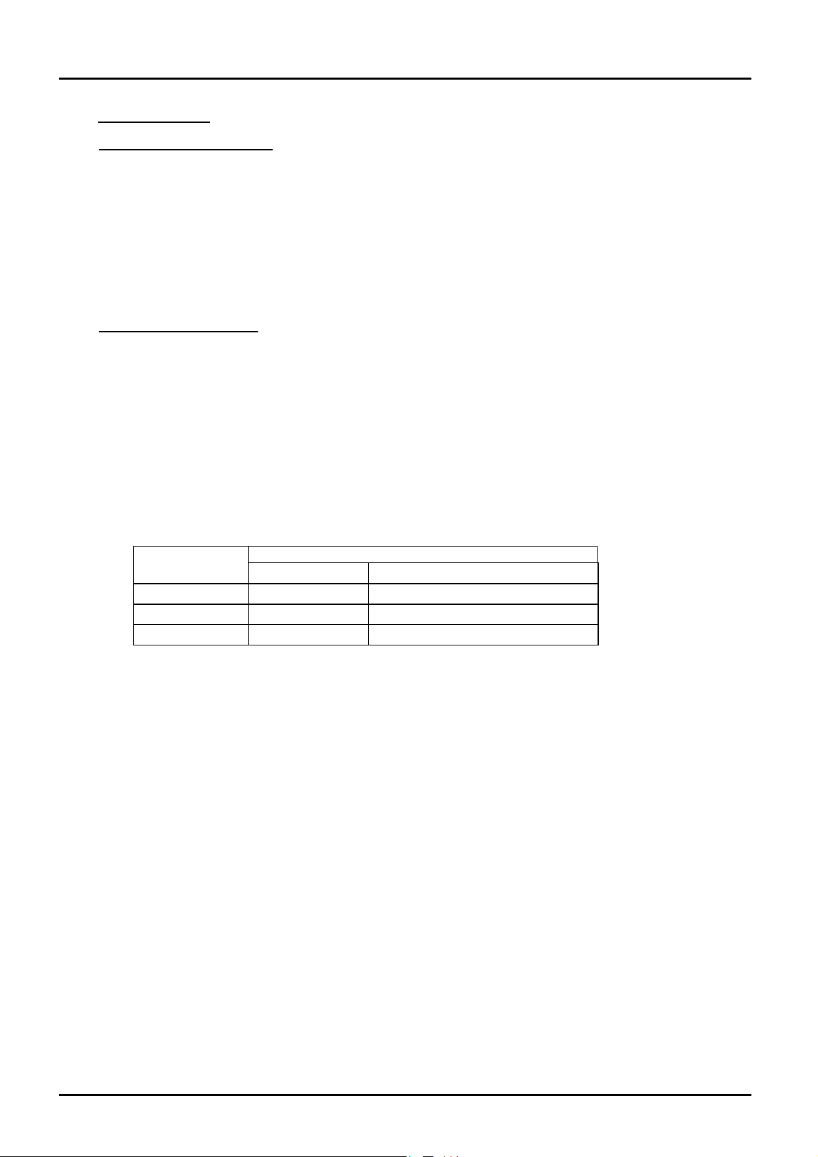
Cable colour Live-Neutral Reversible or Live-Live
Brown to live to either power conductor
Blue to neutral to the other power conductor
Green/Yellow to earth to earth
supply type
3.0
MF09 3
Page 4

MTF 9/15
OPERATING INSTRUCTIONS
3.1 Operating Cycle
Switch on the electrical supply. The temperature controller will become illuminated and may now
be adjusted as described in section 4.0.
The furnace will begin to heat up. The output light on the controller will flash steadily at first and
then flash less as the furnace approaches the desired temperature.
To switch off power to the heating element, switch off or disconnect the supply.
General Operating Notes
3.2
Heating element life is shortened by use at temperatures close to maximum. Do not leave the
furnace at high temperature when not required. The maximum temperature is shown on the
furnace rating label and on the back page of this manual.
Materials such as waxes, case hardening compounds, melting fluxes and other reactive salts
readily penetrate the ceramic tube and attack the wire element, causing premature failure.
Operator Safety
3.3
The ceramic materials used in furnace manufacture become electrically conductive to some extent
at elevated temperatures. DO NOT use any conductive tools within the work tube without
isolating the furnace, unless the tools are earthed (grounded).
Avoid burns. Carbolite can supply tongs, face masks, and heat resistant gloves. Before you
remove a hot object from the furnace make sure you have a safe place to put it down.
4.0
4 MF09
Page 5
MTF 9/15
CONTROLLER OPERATION
4.1 Eurotherm 2132
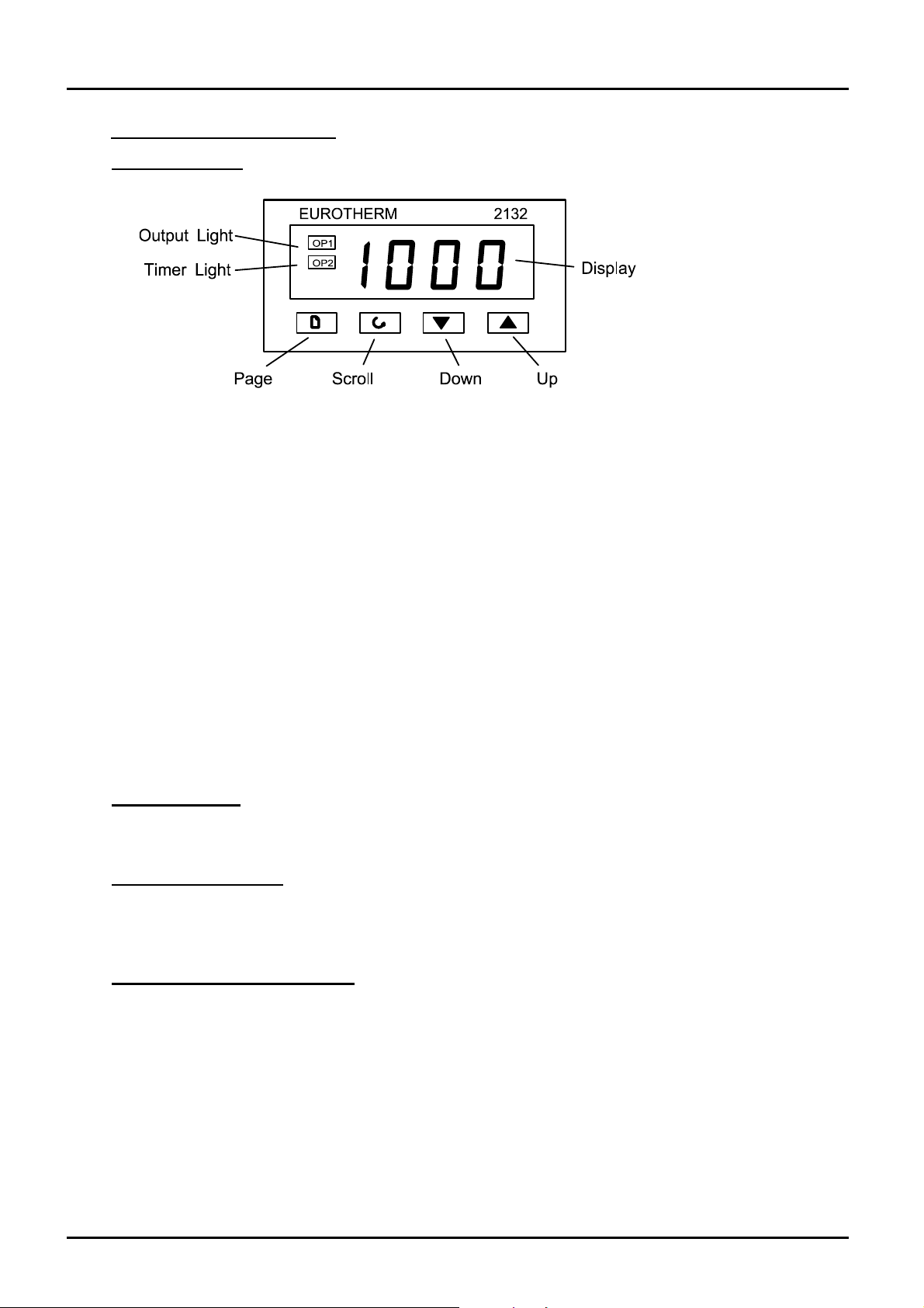
When switched on, the controller lights up, goes through a short test routine, and then displays the
measured temperature and starts to control. The output light glows or flashes as heating occurs.
The Page key allows access to parameter lists within the controller; most lists and parameters
are hidden and cannot be accessed by the operator because they contain factory-set parameters
which should not be changed.
A single press of the page key displays the temperature units, normally set to °C; further presses
reveal the lists indicated in the Navigation Diagram in section 4.6.
The Scroll key 4 allows access to the parameters within a list. Some parameters are display-only;
others may be altered by the operator. Some parameters only appear in appropriate circumstances
– for example, working setpoint does not appear if setpoint ramp rate is Off.
A single press of the scroll key 4 displays the temperature units; further presses reveal the
parameters in the current list indicated in the Navigation Diagram.
To return to the Home list at any time, press Page and Scroll 4 together, or wait for 45 seconds.
The Down T and Up S keys are used to alter the setpoint or other parameter values.
Basic Operation
4.2
Normally no operator action is required other than entering the setpoint, as the 2132 starts to
control on being switched on, as described above.
Altering the Setpoint
4.3
With the display at “home”, showing the measured temperature, press Down T or Up S once to
display the setpoint; press again or hold down to adjust it. The display returns to the measured
temperature when no key is pressed for 0.5 seconds.
Stopping and Starting Control
4.4
It is possible to stop and start the controller without altering the setpoint. Press Scroll 4 until the
legend
Down T or Up S once to show the current on/off state:
m-A (manual/auto) appears. In the 2132, manual means “off” and auto means “on”. Press
mAn for off, and Auto for on. Press T or
S to change between manual and auto (off and on) as required.
Note that timer modes 1 & 3 set the controller to
mAn at the end of the timing period. If the
controller unexpectedly does not control it may be in manual, possibly as the result of previous
use of the timer function.
4.5
MF09 5
Page 6
p
p
f
r
g
s
p
p
MTF 9/15
Altering the Ramp Rate
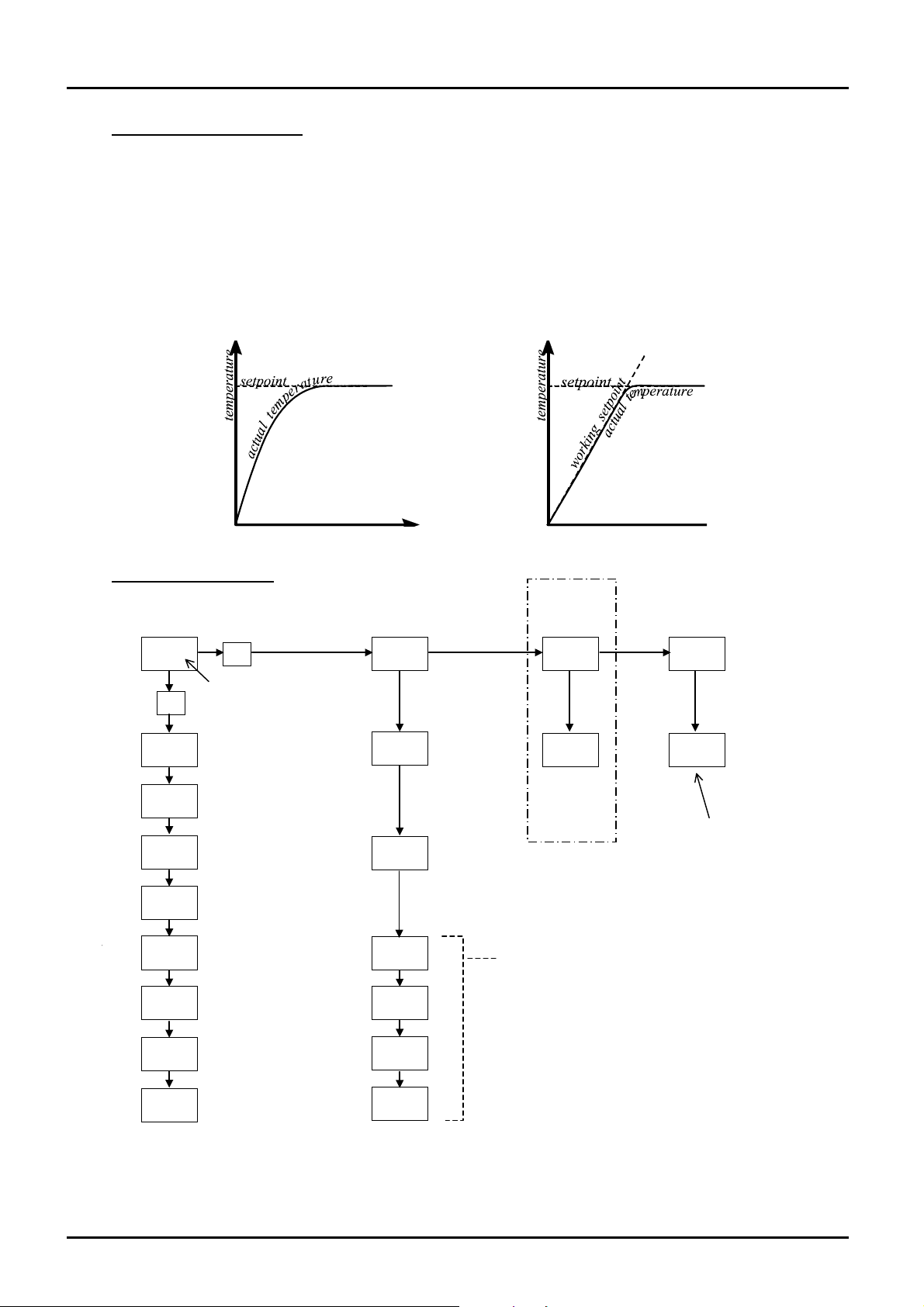
It is possible to limit the rate of heating by setting a ramp rate. Press Scroll 4 until the legend
(SetPoint ramp rate) is displayed. Use Down T or Up S to display and adjust the value.
The ramp rate sets the maximum rate of heating or cooling in degrees per minute. A value of
cancels the ramp rate, allowing heating and cooling at the maximum rate. When this feature is in
use, there is a “working setpoint” which can be viewed at any time by scrolling to
w.SP and
pressing T or S.
Fig 1 and fig 2 indicate the possible difference between running without and with a ramp-to-
setpoint value (depending on the load and the value used).
Navigation Diagram
4.6
SPrr
OFF
Home
List
*C
OP
tmr
*C
measured temperature;
use
T/S
setpoint
output power,
read only
resent only if
SPrr in use
manual/Auto
mAn=off, Auto-on
etpoint ramp rate
OFF or value
timer mode
time remainin
dwell time for
time
20.0 iP oP ACCS
4
4
w.SP
m-A
SPrr
tm.OP
dwel
to access
Input
List
CAL.P
enter
assword
CAL
if user
calibration
Pnt.L
OFS.L
Pnt.H
Output
List
OP.Hi
ower limit
setting, if
resent
user 2-point
calibration
Access
4 4 4
codE
List
or factory access to
lists and parameters
not available to the
operator
StAt
timer status
run or OFF
OFS.H
6 MF09
Page 7

MTF 9/15
4.7 Operation With the Timer
The 2132 can be used as a process timer allowing timed heating or timed delay, according to the
options in the table. There are 5 timer modes, but 2 of them are affected by whether the setpoint
ramp rate feature is being used, making 7 entries in the table. The table also shows the status of
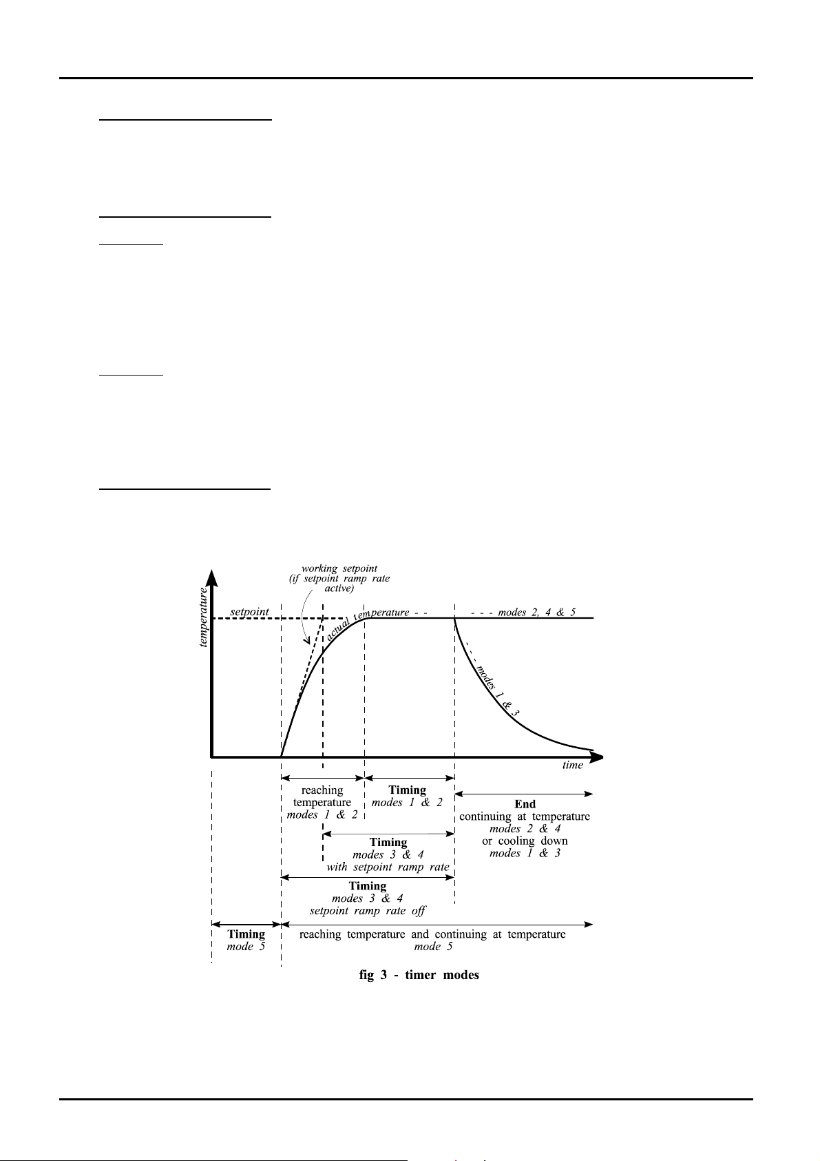
the Timer Light on the 2132. A visual impression of the different modes is given in fig 3.
timer mode description timer light
mode 1
Timed dwell and
switch off
mode 2
Timed dwell and
stay on
mode 3, with SPrr off
Time from cold and
switch off
mode 3, with SPrr
active
Dwell from working
setpoint and switch
off
The timer starts timing when the actual
temperature is within 1°C of the setpoint.
At the end of the timing period, control
switches off (i.e. goes into Manual) to
allow cooling, and EnD flashes on the
display.
The timer starts timing when the actual
temperature is within 1°C of the setpoint.
At the end of the timing period, control
remains on, maintaining the setpoint
temperature, and
End flashes on the
display.
The timer starts timing immediately.
At the end of the timing period, control
switches off (i.e. goes into Manual) to
allow cooling, and End flashes on the
display.
The timer starts timing when the working
setpoint is within 1°C of the setpoint.
At the end of the timing period, control
switches off (i.e. goes into Manual) to
allow cooling, and
End flashes on the
display.
On while temperature is
reaching setpoint.
On during the timing period.
Off from the end of the
timing period.
On while temperature is
reaching setpoint.
On during the timing period.
Off from the end of the
timing period.
On during the timing period.
Off from the end of the
timing period.
On during the timing period.
Off from the end of the
timing period.
mode 4, with Sprr off
Time from cold and
stay on
mode 4, with Sprr
active
Dwell from working
setpoint and stay on
mode 5
Delayed switch on
4.8
The timer starts timing immediately.
At the end of the timing period, control
remains on, maintaining the setpoint
temperature, and
End flashes on the
display.
The timer starts timing when the working
setpoint is within 1°C of the setpoint.
At the end of the timing period, control
remains on, maintaining the setpoint
temperature, and
End flashes on the
display.
The timer starts timing immediately, and
control starts at the end of the timing
period.
There is no “END” condition in this mode.
On during the timing period.
Off from the end of the
timing period.
On during the timing period.
Off from the end of the
timing period.
On during the timing period.
Off from the end of the
timing period.
MF09 7
Page 8
MTF 9/15
Setting the Timer Mode
Scroll to tm.OP; use T or S to view and alter the mode. The mode shows as OPt.1 to OPt.5.
It is not possible to alter the mode while the timer is running; if the mode cannot be altered, scroll
to the StAt parameter and set its value to OFF.
Setting the Time Period
4.9
Method 1
Scroll to
minutes. Use T and S to set or alter the time. Setting
m-A parameter changes to Auto and the StAt parameter changes to run.
Note that the
tmr (time remaining). Use T or S to view the remaining time; the units are always in
tmr automatically activates the timer; the
tmr display shows 0 (zero) during the last minute of timing, and also shows 0 when
the time has expired. The timer light indicates whether timing is still in progress.
Method 2
Scroll to
dwEl, and useT and S to set the timing duration. The advantage of method 2 is that dwEl
need only be set once if repeated use of the same time period is required.
Scroll to
tmr and activates the timer as in method 1.
Running with the Timer
4.10
StAt, and use T or S to set the parameter value to run. This copies the dwell time into
Once the timer is activated by method 1 or 2 above, the control sequence depends on the timer
ode, as previously given in the table. Fig 3 gives another representation of the timer action.
8 MF09
Page 9
MTF 9/15
4.11 Stopping the Timer
To stop the timer at any time while it is running, change the StAt parameter to OFF. This is the
same as reducing tmr to zero. The controller then acts as though at has reached the end of the time
period.
End of Time Period
4.12
Modes 1 and 3: heating stops at the end of timing; the
Modes 2 and 4: heating continues at the end of timing; the
Mode 5: heating starts at the end of the timing period; the
In modes 1 to 4 the alarm message
EnD flashes on the display at the end of timing; the StAt
m-A parameter changes to mAn.
m-A parameter remains at Auto.
m-A parameter remains at Auto.
parameter remains at run.
In mode 5 there is no
Cancelling the Alarm
4.13
End message; the StAt parameter changes to OFF at the end of timing.
To acknowledge (cancel) the EnD alarm, press Page and Scroll together; the StAt parameter
changes to OFF.
Alternatively the alarm may be cancelled by directly changing the
User Calibration
4.14
StAt parameter from run to OFF.
The controller is calibrated for life at manufacture against known reference sources, but there may
be sensor errors or other system errors. User calibration allows compensation for such errors, and
the 2132 allows for a user 2-point calibration. This setting is password protected to avoid
accidental alteration.
Page to
password is entered, the display shows
FACt (factory values, as manufactured) or USEr (user values). Change to USEr.
iP, scroll to CAL.P, and use Up S to alter the password. The password is 3. If the correct
PASS. Scroll to CAL and use T or S to observe the setting
NOTE: before checking the calibration of the controller, or of the complete system, remember to
reset the 2132 to factory calibration values by setting the
CAL.P parameter to FACt.
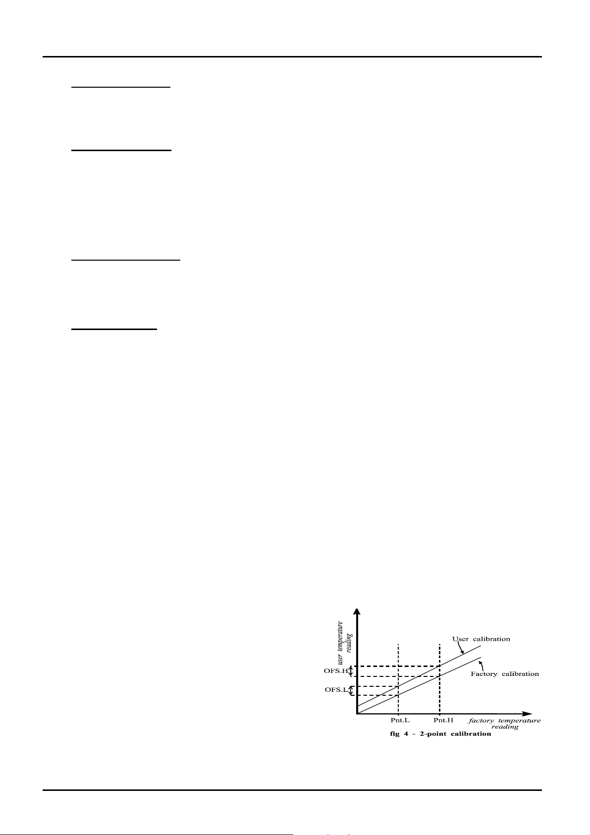
To enter a user calibration, scroll to each or the following parameters in turn and set the desired
values.
Pnt.L low temperature for which an offset is to be entered
OFS.L offset value for the low temperature
Pnt.H high temperature for which an offset is to be entered
OFS.H offset value for the high temperature
Example: the controller reads 3°C low at 400°C, and 5°C low at 1000°C. The parameter values
should be
Pnt.L=400, OFS.L=3, Pnt.H=1000, OFS.H=5.
Negative or positive values can be entered: if
the controller is reading high, negative offsets
would be appropriate.
Fig 4 gives a graphical representation of the 2-
point calibration.
5.0
MF09 9
Page 10

MTF 9/15
MAINTENANCE
5.1 General Maintenance
The furnace does not require any routine preventative maintenance. The outer surfaces may be
cleaned with a damp cloth. Do not allow water to enter the interior of the furnace. Do not clean
with organic solvents.
Calibration
5.2
After prolonged use the controller and/or thermocouple could require recalibration. This would be
important for processes which require accurate temperature readings or which use the furnace
close to its maximum temperature. A quick check using an independent thermocouple and
temperature indicator should be made from time to time to determine whether full calibration is
required. Carbolite can supply these items.
See also the instructions for calibrating the controller, section 4.14.
After Sales Service
5.3
Carbolite’s service division (Thermal Engineering Services) has a team of Service Engineers
capable of repair, calibration and preventive maintenance of furnace and oven products at our
customers’ premises throughout the world. We also sell spares by mail order. A telephone call or
fax often enables a fault to be diagnosed and the necessary spare part despatched.
Each furnace has its own record card at Carbolite. In all correspondence please quote the serial
number, model type and voltage given on the rating label of the furnace. The serial number and
model type are also given on the front of this booklet when supplied with a furnace.
To contact Thermal Engineering Services or Carbolite see the back page of this manual.
Recommended Spares Kits
5.4
Carbolite can supply individual spares, or a kit of the items most likely to be required. Ordering a
kit in advance can save time in the event of a breakdown.
Each kit comprises one wound tube element, one thermocouple, and a fuse.
When ordering spares please quote the model details as requested above.
Power Adjustment
5.5
The furnace control system incorporates electronic power limiting, which in this model is used as
described in section 9.2. The power limit parameter OP.Hi may be accessible to the operator, but
should not generally be altered.
Do not adjust the power limit in a 220-240V model to 100% - the element will burn out.
6.0
10 MF09
Page 11
MTF 9/15
REPAIRS & REPLACEMENTS
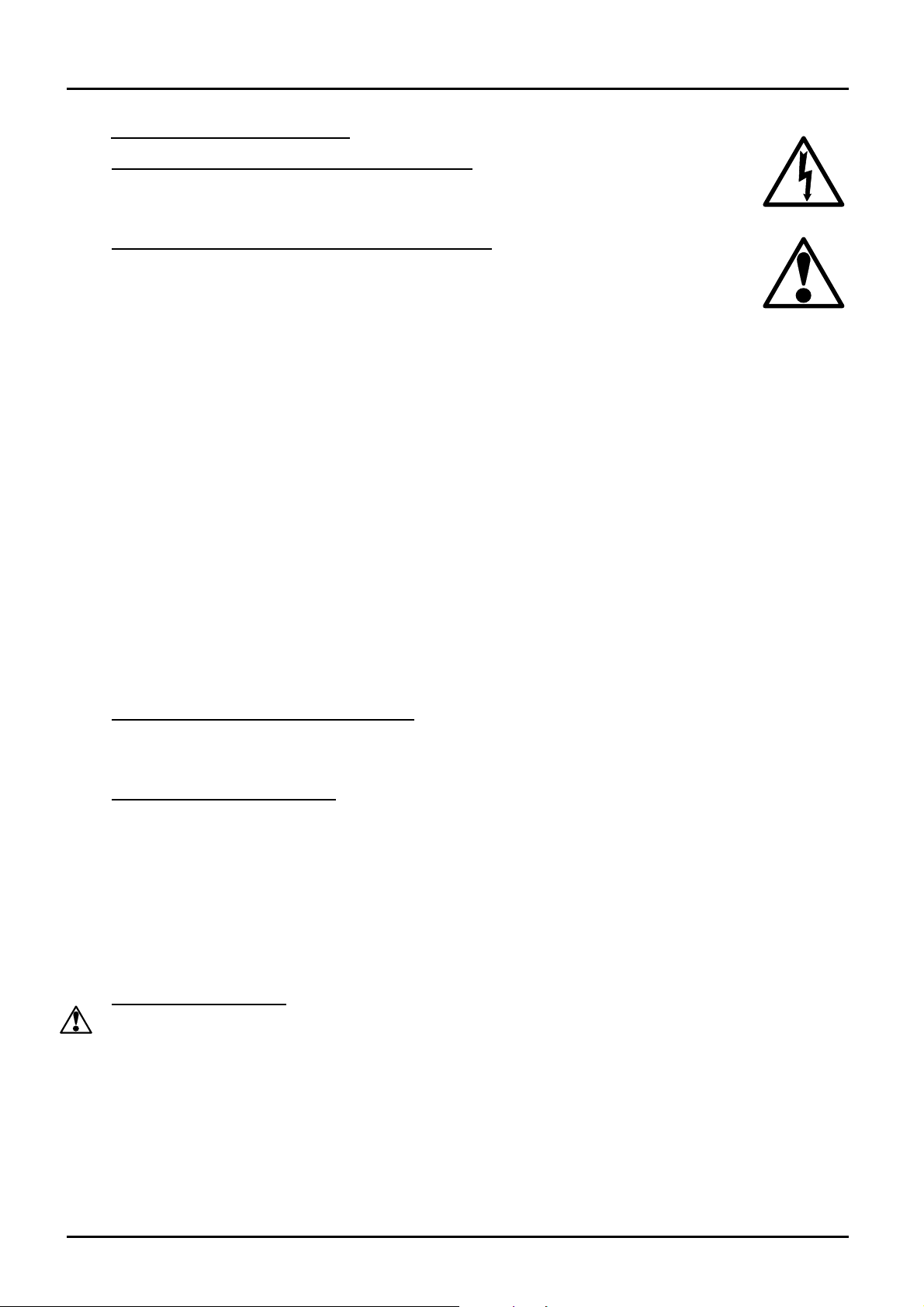
6.1 Safety Warning – Disconnection from Supply
Always ensure that the furnace is disconnected from the supply before repair work
is carried out.
Safety Warning - Refractory Fibrous Insulation
6.2
This furnace contains refractory fibres in its thermal insulation. These materials may
be in the form of fibre blanket or felt, vacuum formed board or shapes, mineral wool
slab or loose fill fibre.
Normal use of the furnace does not result in any significant level of airborne dust from these
materials, but much higher levels may be encountered during maintenance or repair.
Whilst there is no evidence of any long term health hazards, we strongly recommend that safety
precautions are taken whenever the materials are handled.
Exposure to dust from fibre which has been used at high temperatures may cause
respiratory disease.
When handling fibre always use an approved mask, eye protection, gloves and long
sleeved clothing.
Avoid breaking up waste material. Dispose of waste fibre in sealed containers.
After handling rinse exposed skin with water before washing gently with soap (not
detergent). Wash work clothing separately.
Before commencing any major repairs we recommend reference to the European Ceramic Fibre
Industry Association Bulletin No. 11 and the UK Health and Safety Executive Guidance Note
EH46.
We can provide further information on request. Alternatively our service division can quote for
any repairs to be carried out at your premises or ours.
Temperature Controller Replacement
6.3
Ease apart the two lugs at the side; grip the instrument and withdraw it from its sleeve; push in the
replacement.
Thermocouple Replacement
6.4
Disconnect the furnace from the supply; disconnect the thermocouple from the controller, noting
the connections.
Release the screw which secures the thermocouple sheath.
Reassemble with a new thermocouple, ensuring that the new one is in good contact with the tube
wall.
Ensure that the negative side of the thermocouple (marked blue) is connected to the negative
terminal of the controller.
Element Replacement
6.5
See section 6.2- wearing a face mask is recommended.
The furnace is heated by resistance wire wound onto a small ceramic tube. This is centred in a
cylinder of insulation. The element is terminated by bringing the ends of the heating wire out
through grooves cut in the ends of the insulation cylinder. The wire is electrically insulated from
the foil, which covers the insulation, by ceramic beads and by discs of glass fibre cloth which
cover the ends of the insulation cylinders.
To replace the element it is necessary to cut the binding which attaches the element to the chassis.
Replacement binding is supplied with the spare element.
MF09 11
Page 12

MTF 9/15
Upon reassembly ensure that the element wire is deeply embedded in the grooves in the ends of
the insulation and held away from the foil by insulation beads. The foil should be neatly and
firmly wrapped so that it positively locates the beads.
When refixing the wrapped element position the beads just above edge of the metal channel to
maximise the clearance between the outer case and the wires.
Solid State Relay Replacement
6.6
The solid state relay (SSR) fitted to this model is a flat black oblong component with four
numbered wire connections. To replace, simply disconnect the old and fit the new, ensuring that
the numbered connections are made to the correct places.
7.0
12 MF09
Page 13

FAULT ANALYSIS
MTF 9/15
A. Furnace Does Not Heat Up
1.
The HEAT light
is ON
2.
The HEAT light
is OFF
The controller
There are no
B.
Furnace Overheats
1.
The HEAT light
goes OFF with
the instrument
switch
2.
The HEAT light
does not go off
with the
instrument
switch
Æ
The heating
element has failed
The controller
shows a very high
temperature or a
code such as S.br
shows a low
temperature
lights glowing
on the
controller
Æ
The controller
shows a very high
temperature
Æ
The controller
shows a low
temperature
Æ
The SSR has failed
“ON”
8.0
Æ
Check also that the SSR is working
correctly
Æ
The thermocouple has broken or has a
wiring fault
Æ
The door switch(es) (if fitted) may be
faulty or need adjustment
Æ
The contactor (if fitted) may be faulty
Æ
The SSR could be failing to switch on due
to internal failure, faulty logic wiring from
the controller, or faulty controller
Æ
The SUPPLY
light is ON
Æ
The SUPPLY
light is OFF
Æ
The controller is faulty
Æ
The thermocouple may have been shorted
out or may have been moved out of the
heating chamber
Æ
The thermocouple may be mounted the
wrong way round
Æ
The controller may be faulty
Æ
Check for an accidental wiring fault which
could have overloaded the SSR
Æ
The controller may be
faulty or not receiving a
supply due to a faulty
switch or a wiring fault
Æ
Check the supply fuses and
any fuses in the furnace
control compartment
MF09 13
Page 14
N
r
pink
grey
MTF 9/15
CIRCUIT DIAGRAM
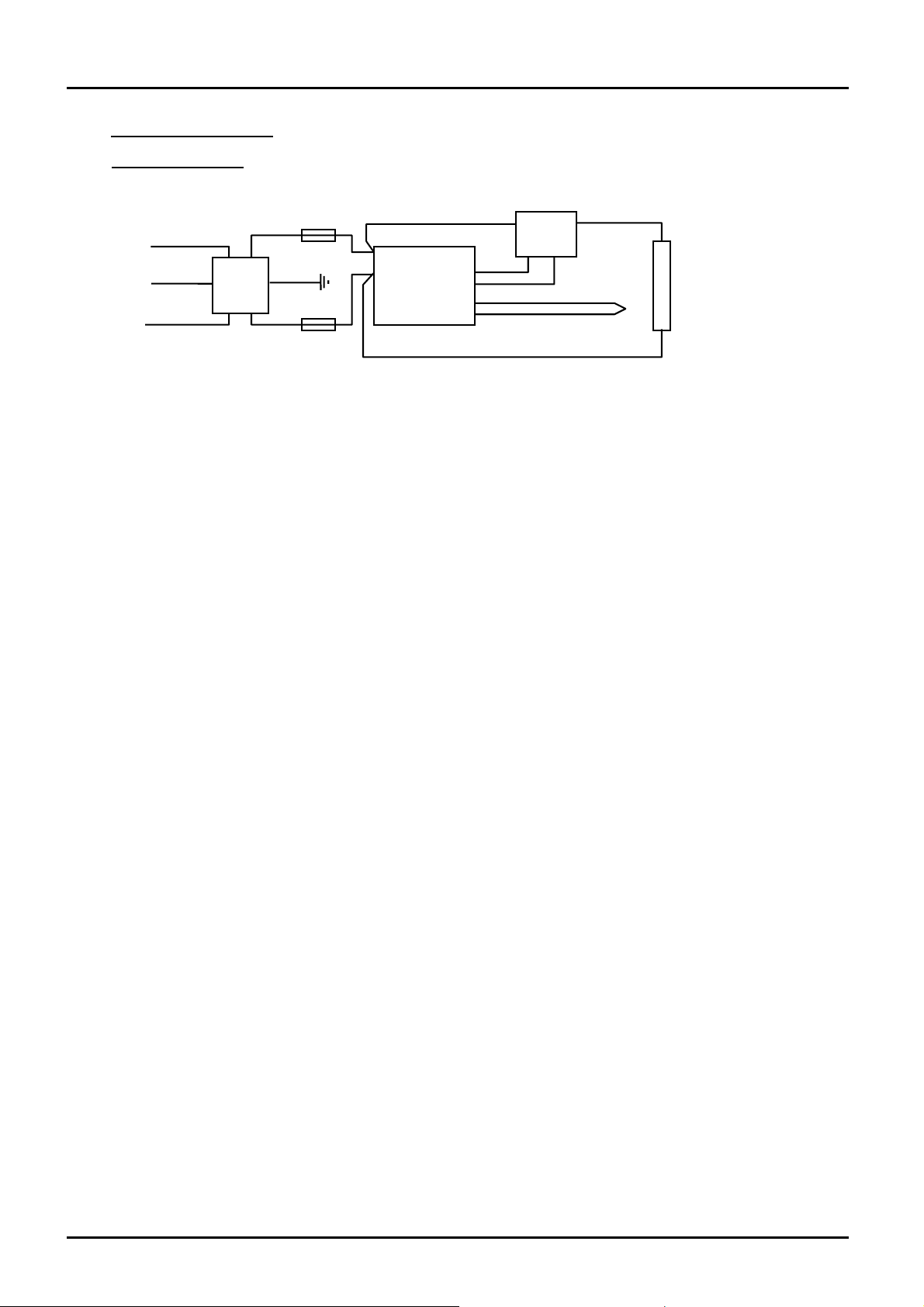
8.1 Circuit Diagram
9.0
L
PE
Re
Re
filter
Green/Yellow
Blue
2A
2A
L
N
controlle
thermocouple
Blue
SSR
34
21
heating
element
14 MF09
Page 15

MTF 9/15
FUSES & POWER CONTROL
9.1 Fuses
Access to internal fuses is by removal of the outer case.
Fuses: 2A 20mm x 5mm type F.
Power Control
9.2
In this model the same heating element is used for 110-120V models and 220-240V models.
Electronic power limiting in the 2132 controller is used to reduce the power in the 220-240V
model.
The correct power limit settings (parameter
220-240V model: 50%
110-120V model: 100%
Note: To reduce the wattage on 240V to the same as on 120V, a power limit of 25% ought to be
applied. This is not necessary, and would result in poorer temperature control.
OP.Hi) for the furnace are as follows:
MF09 15
Page 16

Thank you for reading this data sheet.
Please contact us for a quotation:
Head Office (UK)
P.O. Box 2124
Chelmsford
Essex CM1 3UP
England
Tel: +44 (0)1245 600 560
Fax: +44 (0)1245 600 030
Email:
General Information/Sales:
Accounts Department:
USA Office
233 Rogue River Highway #425
Grants Pass
Oregon 97527-5429
USA
Switzerland Office
Zugerstrasse 46
6314 Unterägeri
Zug
Switzerland
Tel: +41 41 541 5877
Fax: +41 41 541 5878
Email:
General Information/Sales:
Accounts Department:
Latin America Office
World Trade Centre
Apartado 0832-00708
Ciudad de Panamá
República de Panamá
Tel: +1 503 206 0941
Fax: +1 541 610 1646
Email:
General Information/Sales:
Accounts Department:
Tel: +507 836 5304
Fax: +507 399 1804
Email:
General Information/Sales:
Accounts Department:
 Loading...