

Carbolite MRF 16, MRF 22 Installation & Operating Instructions Manual
MF 55-GB 1.21
Installation, Operation &
Maintenance Instructions
Microwave Assisted Technology
MRF 16/22
Important note:
This product needs to be “burnt off” and its elements conditioned before it can be used. See
section 3.6 for details.
This manual is for the guidance of operators of the MRF 16/22 furnace and should be read
before the furnace is connected to the electricity supply. It contains information required for
safe and trouble-free furnace operation. If, however, any questions remain unanswered please
contact our service division at the address at the end of this manual.

MRF 16/22
2 MF 55-GB 1.21
Contents
1 Introduction to the furnace 6
1.1 SPECIFICATION 6
1.2 OPERATING MODES 6
1.3 3508 CONTROLLER/PROGRAMMER [SEE SECTION 5] 6
1.4 2132 OVER TEMPERATURE CONTROLLER [SEE SECTION 10] 6
2 Safety 7
2.1 GENERAL WARNINGS 7
2.2 OPERATOR SAFETY - HEAT 7
2.3 DOOR LATCHES AND SAFETY INTERLOCKS 7
2.4 SAFETY PRECAUTIONS WHEN OPENING THE DOOR 7
2.5 USE OF PROBES 8
2.6 MICROWAVE ARCING 8
2.7 EXPLOSIVE MATERIALS 8
2.8 USE AFTER TRANSPORT OR STORAGE IN HUMID CONDITIONS. 8
WARNING SYMBOLS 9
3 Installation 10
3.1 UNPACKING & HANDLING 10
3.2 LOCATION 10
3.3 INTERNAL UNPACKING 11
3.4 ELECTRICAL CONNECTIONS 11
3.5 LOW VOLTAGE COMPENSATION 11
3.6 SWITCHING ON FOR THE FIRST TIME 13
4 General operating notes 14
4.1 OPENING THE DOOR 14
4.2 LOADING THE FURNACE 14
4.3 INSULATION CRACKING 14
4.4 THERMOCOUPLES - AGEING 14
4.5 THERMOCOUPLES – LOW TEMPERATURES 15
4.6 THERMAL CUT-OUTS 15
4.7 RATING LABEL, RS 232 PORT AND COOLING FANS 16
5 Controllers, lights and indicators 17
5.1 CONTROL PANEL [SEE FIG 5.1] 17
5.2 CONTROLLER HOME DISPLAY LAYOUT – KEYS AND INDICATORS 19
5.3 CONTROLLER PAGES: TEMPERATURE AND PROGRAMMING 20

MRF 16/22
MF 55-GB 1.21 3
5.4 CONTROLLER PAGES: MICROWAVE 21
6 Temperature control 22
6.1 CHANGING THE SETPOINT TEMPERATURE (SP) 22
6.2 RAMP TO SETPOINT 22
7 Microwave control 23
7.1 MW POWER LEVEL SETTING 23
7.2 COUNTDOWN TIMER DURATION SETTING [SEE FIGURE 5.5] 23
7.3 TO SWITCH ON/OFF THE MICROWAVE POWER [SEE FIGURE 5.5] 23
7.4 PULSED MICROWAVE POWER [SEE FIGURE 5.6] 23
7.5 NOTES 23
8 Programming 24
8.1 PROGRAMMING NOTES 24
8.2 CREATING A PROGRAM (SEE GLOSSARY ON PAGE 50) 24
8.3 RUNNING THE CURRENT PROGRAM 25
8.4 TO PAUSE (HOLD) A PROGRAM 26
8.5 TO STOP AND RESET A PROGRAM 26
8.6 TO RUN A DIFFERENT PROGRAM 26
8.7 PROGRAM CYCLING 26
8.8 PROGRAM STATUS 26
8.9 HOLDBACK 27
8.10 POWER FAILURE RECOVERY 27
8.11 PROGRAM EXAMPLE 1 28
8.12 PROGRAM EXAMPLE 2 30
9 Main controller navigation diagrams 32
9.1 NAVIGATION DIAGRAM - NO PROGRAM RUNNING 32
9.2 NAVIGATION DIAGRAM - PROGRAM RUNNING 33
9.3 NAVIGATION DIAGRAM – MAIN CONTROLLER CALIBRATION OFFSET 34
9.4 USER CALIBRATION– MAIN CONTROLLER 35
10 Over temperature controller eurotherm 2132 36
10.1 DESCRIPTION 36
10.2 BASIC OPERATING INSTRUCTIONS 36
10.3 NAVIGATION DIAGRAM - OVER TEMPERATURE CONTROLLER 36
10.4 USER CALIBRATION OF OVER TEMPERATURE 37
10.5 NAVIGATION DIAGRAM - CALIBRATION OF OVER TEMPERATURE CONTROLLER 37

MRF 16/22
4 MF 55-GB 1.21
11 Digital communication 38
11.1 RS232 COMMUNICATION ADDRESSING: 38
11.2 RS232 COMMUNICATION CABLES 38
12 Maintenance 39
12.1 CLEANING 39
12.2 DECONTAMINATION 39
12.3 REGULAR MICROWAVE SAFETY CHECKS 39
12.4 CHECK THE OPERATION OF THE DOOR SAFETY INTERLOCKS 39
12.5 THERMOCOUPLE SHEATH AGING 39
12.6 OTHER ELECTRICAL COMPONENTS 40
12.7 ELEMENT GLAZE 40
12.8 PESTING 40
12.9 TEMPERATURE CALIBRATION 40
12.10 MICROWAVE POWER DETERMINATION 41
12.11 AFTER SALES SERVICE 41
12.12 SPARE PARTS 41
13 Repairs & replacements 42
13.1 SAFETY WARNING – DISCONNECTION FROM SUPPLY 42
13.2 SAFETY NOTE - REFRACTORY FIBROUS INSULATION 42
13.3 ACCESS PANELS REMOVAL 42
13.4 TEMPERATURE CONTROLLER REPLACEMENT 43
13.5 FUSE SIZES AND FUSE REPLACEMENT 44
13.6 THERMOCOUPLE REPLACEMENT 45
13.7 THERMOCOUPLE SHEATH REPLACEMENT 45
13.8 ELEMENT REPLACEMENT 46
13.9 ELEMENT MICA WASHER REPLACEMENT 48
14 Fault analysis 49
15 Environment 50
16 Specification 50
17 Glossary of terms 51

MRF 16/22
MF 55-GB 1.21 5
List of Figures
Figure Title Page
3.1 Fork lift access panel 10
3.2 Electrical connections 11
4.1 Rating label, RS 232 connection and cooling fans 15
5.1 Control panel 17
5.2 Controller keys and indicators 18
5.3 Temperature control 19
5.4 Program editing 19
5.5 Microwave control 20
5.6 Microwave pulse control 20
8.1 Program example 1 27
8.2 Program example 2 28
11.1 Over temperature controller keys and Indicators 34
12.1 RS232 cable connections 38
14.1 Access panels 43
14.2 Internal fuses 44
14.3 Thermocouple and sheath assembly 45
14.4 Element braid clip tool 46
14.5 Measure and note element tail length before removing 46
14.6 Element assembly parts 47

MRF 16/22
6 MF 55-GB 1.21
1 Introduction to the furnace
Sections 1 and 2 of this manual must be read before connecting this furnace to a power
supply.
1.1 Specification
The maximum temperature is 1600°C.
The usable capacity is 22 litres.
The maximum recommended load weight is an evenly distributed 7.5Kg. Concentrated loading
will damage the hearth unless a hearth tile is used.
For the full specification refer to the table in section 17.
1.2 Operating modes
The MRF 16/22 can be used as a conventional radiant heating furnace, operating continuously
at a set temperature or following a program profile. The microwave (MW) power can be applied
continuously or as part of the program. The MW power can be applied without the radiant
heating for performance testing purposes or other applications.
1.3 3508 Controller/programmer [See section 5]
The 3508 is a digital temperature controller/programmer made by Eurotherm which uses PID
(Proportional Integral Derivative) algorithms to give excellent temperature control. The
controller is available in 4 options for the number of programs and program segments that can
be stored.
P1 1 program 20 segments
P10 10 programs 500 segments
P25 25 programs 500 segments
P50 50 programs 500 segments
1.4 2132 Over temperature controller [See section 10]
The 2132 over temperature controller made by Eurotherm is a digital instrument with a latching
alarm.
It features easy setting of an over temperature Setpoint.
MRF 16/22
MF 55-GB 1.21 7
2 Safety
2.1 General warnings
CAUTION. Personnel must not be exposed to the microwave energy radiated from the
microwave generator. All connections, waveguides, flanges, gaskets, etc., must be secure in
order to ensure that microwave leakage remains below specified limits. Never operate the
furnace without an absorbing load. To maintain the microwave leakage at an acceptable value,
the microwave heating equipment shall be periodically inspected and kept in good working
condition.
COMPETENT people only should be permitted to install, maintain and operate the furnace.
Installation and maintenance should be done by a qualified electrician. Operating should be
done by a person who has read this manual and is aware of and understands the safety issues
in using high temperature electrically heated equipment.
If this furnace is used in a way not specified by Carbolite, the protection provided by the
furnace may be impaired.
2.2 Operator safety - heat
The temperatures of all external surfaces are within limits set by BS EN 61010. The chimney
will get hot when the furnace is operated at high temperatures – do not touch.
2.3 Door latches and safety interlocks
When the door is closed and latched both the radiant heating and microwave power circuits
are enabled.
When the door is open, both the radiant heating and microwave power circuits are disabled.
When the MW power is on the door is locked.
The operation of these switches should be checked periodically. See section 13.3 for
instructions.
2.4 Safety precautions when opening the door
Take great care when loading or unloading the furnace chamber. [See also section 4.1].
• Do not open the door at high temperatures. If possible, do not open it above 200°C and
keep the door open for as short a period as possible.
• Wear heat-resistant clothing, including appropriate hand and face protection suitable for
high levels of radiated heat, if it is necessary to load or unload work at elevated
temperatures.
• Always wear eye protection if opening the door when the temperature is between 200°C
and ambient. Small fragments of glaze may be ejected from the surface of the elements.
• Objects which are inflammable or could be damaged by radiated heat should not be kept
near the furnace.
• Before removing a hot object from the furnace, make sure you have a safe place to put it
down.
• Read section 4.1 for further notes about opening the door.
MRF 16/22
8 MF 55-GB 1.21
2.5 Use of probes
DO NOT INSERT ANY PROBES INTO THE FURNACE CHAMBER either down the chimney,
round the door or by modification to the furnace in any way.
MICROWAVE ENERGY! Do not insert any metal objects into the case!
HIGH VOLTAGE! Do not insert any metal objects into the case!
2.6 Microwave arcing
Precautions should be taken to avoid the formation of arcs in the furnace. These may be
caused by some materials, especially metals, their shapes and locations.
2.7 Explosive materials
The furnace must not be used to heat materials which could explode, or which could emit
gases that could form explosive mixtures.
Great care should be taken in attempting to translate protocols developed in other apparatus
for use in a Microwave Assist Technology (MAT) furnace. Unlike conventional radiant heating
furnaces, MAT furnaces apply MW heating instantaneously to susceptible samples. Unlike in
MW only apparatus thermal reactions are not contained within or regulated by a reaction
vessel or bomb. In particular it is recommended that initially only gradual heating and small
sample sizes are employed until a protocol has been perfected. This is especially important in
circumstances where instantaneous heating from the application of MW energy may initiate an
exothermic reaction in the sample.
2.8 Use after transport or storage in humid conditions.
After transport or storage in humid conditions this furnace may fail to reach electrical safety
standards due to a build up of condensation. The furnace must be operated for at least one
hour at or above 500°C to dry it out.
The furnace can not be assumed to meet safety standards during the drying out process.
If the furnace is being switched on for the first time, then following the burn off process will dry
the furnace.
Note; if after following the drying procedure the furnace has note fully dried then repeat the
procedure, if in doubt contact Carbolite.
MRF 16/22
MF 55-GB 1.21 9
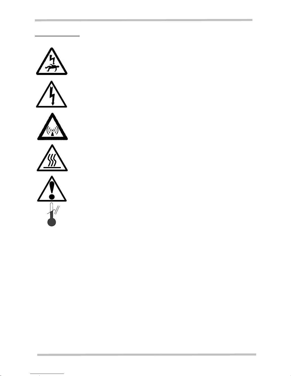
Warning symbols
The following warning symbols are used in this manual and on the product.
DANGER – hot surface. Read any warning printed next to this symbol.
WARNING: all surfaces of a furnace may be hot.
DANGER – read any warning printed next to this symbol.
FAULT – read any information printed next to this symbol.
DANGER – Microwave Energy – read any warning printed next to this
symbol.
DANGER OF DEATH – HIGH VOLTAGE – read any warning printed next to
this symbol.
DANGER of electrical shock – read any warning printed next to this symbol.

MRF 16/22
10 MF 55-GB 1.21
3 Installation
3.1 Unpacking & handling
When unpacking or moving the furnace, always lift it by its base. Never lift it by the door.
Use a forklift, pallet truck or scissor lift to move the furnace whenever possible.
Remove the outer cardboard box.
Remove the foam packing.
Remove the clear plastic film.
To move the furnace using a fork lift, first remove the fork lift access panel at the front of the
furnace as shown in figure 3.1 below.
Do not remove the internal packing until after locating the furnace as described below.
To remove the panel slacken 2 screws at the sides using a large cross head screwdriver,
then pull forward then right to remove. The screws should come out with the panel. The 2
screws are inside holes located by the arrows in figure 3.1 above.
3.2 Location
Place the furnace in a well ventilated room, away from other sources of heat, on a suitable
surface [note the weight of the furnace is 290kg] which is resistant to accidental spillage of
hot materials. Do not mount the furnace on an inflammable surface. Do not mount the
furnace where radiated heat from an open door could cause damage.
Ensure that there is at least 75mm of free space around the furnace and Carbolite
recommends 1.5 meters of free space above the furnace. Do not obstruct any of the fan
inlets or outlets.
If the furnace is to be used in a process which could liberate hazardous gases, then it
should be installed together with a suitable fume extraction system. A direct connection to
the furnace chimney should not be made.
Ensure that the furnace is placed in such a way that it can be quickly switched off or
Figure 3.1 Fork lift access panel

MRF 16/22
MF 55-GB 1.21 11
disconnected from the electrical supply - see below.
3.3 Internal unpacking
Lift the door latches and open the door. When the door was shut, a thin piece of foam was
placed between the door and furnace box. Remove all traces of this from the door area.
Remove the small foam blocks from either side of the door insulation plug.
Remove the slabs of foam from inside of the furnace chamber.
CAREFULLY !! Remove the strips of foam packing from around the elements. The elements
are very brittle. Pull the strips forward more than sideways.
3.4 Electrical connections
Connection by a qualified electrician is recommended.
Check the furnace rating label before connection. [See section 5.5 for location]. The supply
voltage should agree with the voltage on the label, and the supply current capacity should
be sufficient for the amperage on the label.
The power supply to this product must be connected through an isolating switch operating
on all conductors, the switch must be in easy reach of the operator. It must be fused to give
a level of discrimination between the MRF 16/22 internal fuses and the external isolation
fuses. See Product rating label for voltage and specification. [See section 13.5 for the
internal fuses fitted].
A line plug may be used after the isolating switch. The line plug must allow the protective
earth (ground) to be connected before the conductors and disconnected after them. The
supply point must be marked as the disconnecting device for the furnace.
The supply MUST incorporate an earth (ground).
The supply cable must enter the furnace case through an appropriate strain relief guard.
If an earth leakage device is fitted then it must be calibrated to 28mA to avoid nuisance
tripping.
MRF 16/22 connections 3 Phase supply specification
3 phase + neutral (star) Delta
Voltage supply
380V – 415V 200V– 240V
Main Internal fuse 25A 40A
Terminal colour
L1 Black Phase 1 Phase 1
L2 Black Phase 2 Phase 2
L3 Black Phase 3 Phase 3
N Blue Neutral N/A
PE Green/Yellow To earth / Ground To earth / Ground
3.5 Low voltage compensation
If the supply voltage proves to be routinely below the nominal figure for which the furnace
Figure 3.2 Electrical connections

MRF 16/22
12 MF 55-GB 1.21
has been set up, there is a “+2%” position on the transformer primary side which may be
used to compensate for this.
Safety note: Refer to section 2.1.

MRF 16/22
MF 55-GB 1.21 13
3.6 Switching on for the first time
To minimise the chance of transport damage to the insulation, the binder in the insulation has
not been burnt off. (Burn off is the process of burning out organic binders from the insulation
boards). During this process the structure of the insulation changes and it can become brittle.
The furnace must be burnt off and the elements conditioned before it is ready for use.
1 Set microwave power to 50% and run for 2 hours [See section 7] to burn off any binder in
the insulation.
2 Open door and leave to cool for 30 minutes.
3 Make sure the Setpoint temperature is set to -20°C, or the furnace will not cool down at the
end of the cycle.
4 Make sure the microwave timer is off and or set to zero, or the microwave power will come
on after the program has finished. [See section 7]
5 Create the following program for conditioning the elements. [See section 8]
Ramp Units: Min
Cycles: 1
Event Outs (No microwave power)
Holdback Type (Off)
Ramp to 800°C at 3.3°C per minute
Ramp to 1500°C at 5.0°C per minute
Dwell for 60 minutes.
Ramp to 1600°C at 5.0°C per minute
Dwell for 15 minutes
End Type Reset
6 Run the conditioning cycle. Note if the elements do not fully condition run the program
again.
The elements should have a glazed appearance if properly conditioned. Note there may be
some “patchy” areas on the surface of the elements where some of the glazing has flaked off,
this is normal.
MRF 16/22
14 MF 55-GB 1.21
4 General operating notes
This manual explains how to operate and maintain the MRF 16/22.
Heating element life is shortened by use at temperatures close to maximum, so avoid leaving
the furnace at high temperatures when not required. The furnace can be cycled between room
temperature and maximum without a detrimental effect on element life. The maximum
temperature is 1600°C.
Operating the furnace below 600°C for long periods may cause pesting of the elements. See
section 12.6.
Insulation life will be shortened if heat up rates are used in excess of 500°C/hr (8.33°C/min)
up to 1200°C and 300°C/hr (5°C/min) from 1200°C up to 1600°C.
4.1 Opening the door
Take great care when loading or unloading the furnace chamber. Also read the safety
precautions in sections 2.3 and 2.4.
• At all times operate the door gently to avoid mechanical shock. The heating elements and
the insulation are very susceptible to mechanical shock.
• Opening the door when the furnace is very hot can cause hot air to be drawn towards the
thermal cut out and activate it [See section 4.6].
4.2 Loading the furnace
When loading the furnace ensure that nothing is placed within 25mm of the elements, and
avoid shielding the thermocouple from the heating elements.
The thermocouple is designed to sense the temperature near the heating element, but if a
large object is placed in the chamber it may record the average temperature of the object and
the elements, which can lead to overheating of the elements. Allow large objects to gain heat
at a lower temperature and then reset the controller to a temperature close to the desired
maximum.
Avoid placing large objects within 50mm of the back wall. The microwave power enters the
chamber at the centre of the back wall.
Take care that nothing touches the elements when loading or unloading.
4.3 Insulation cracking
The insulation material is susceptible to surface cracking arising from high temperature cycling;
this is a normal occurrence and such cracking is not detrimental to the performance of the
furnace.
4.4 Thermocouples - ageing
Regular use at high temperatures will cause the thermocouples to deteriorate resulting in false
readings, this is known as ‘ageing’. This will cause the furnace to run at a higher temperature
than indicated.
Customers are advised periodically to check the thermocouple output, either by a calibration
test or by comparing the output with a new reference thermocouple at the required process
temperature.
Failure to check the thermocouple regularly may result in overheating of the work and the
MRF 16/22
MF 55-GB 1.21 15
furnace, with consequent damage to both.
4.5 Thermocouples – low temperatures
At temperatures below 600°C the thermocouples will not give accurate readings. When the
furnace is started from cold they may show a negative temperature.
If the Setpoint temperature is at 0°C, this negative temperature reading will cause the heating
power to come on. To ensure that heating power does not come on when it is not required,
turn the Setpoint temperature down to -20°C. This will ensure that radiant heating power is not
applied when the furnace is not in use, after the end of a program or when using only the
microwave power.
This furnace is designed for operation over 800°C, it may be run below this temperature, but
accurate temperature measurement and stability are not assured.
4.6 Thermal cut-outs
A self resetting thermal cut-out is located on the back of the magnetron.
A self resetting thermal cut-out, located in the element circuit transformer, cuts power if the
transformer core overheats.
If any of the thermal cut-outs are activated, then power to the elements and microwave is cut
and a red fault light on the control panel is illuminated.
MRF 16/22
16 MF 55-GB 1.21
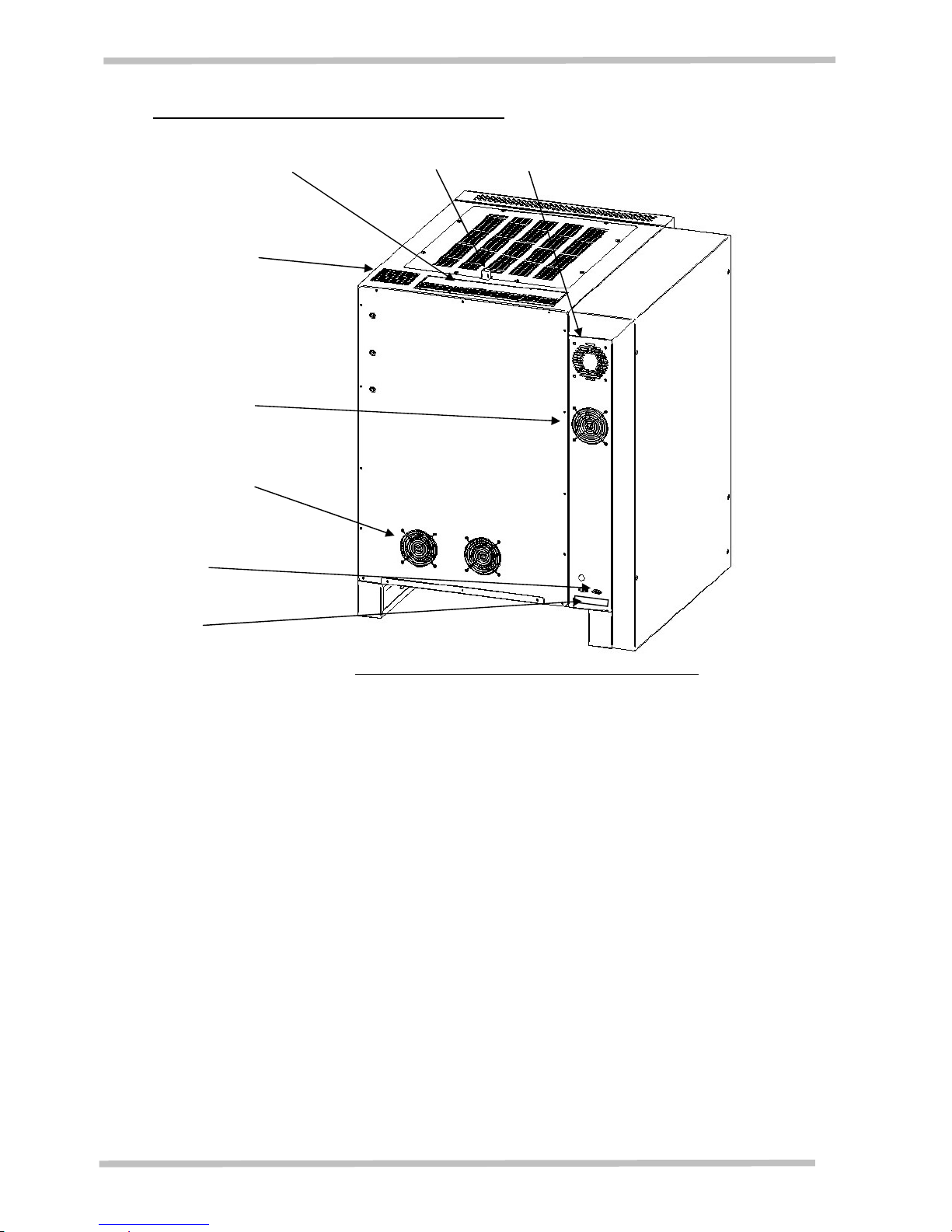
4.7 Rating label, RS 232 port and cooling fans
Case cooling fan outlet Chimney Control box cooling fan outlet
Magnetron cooling
fan outlet
Magnetron cooling
fan intake
Microwave circuit
cooling fans outlets
RS 232 port
Rating label
The case and control box cooling fans will be on when the power is turned on.
The magnetron and microwave circuit cooling fans will switch on 10 seconds before the
microwave power comes on and will remain on for a few minutes after the MW power goes off.
Figure 4.1 Rating label, RS 232 port and cooling fans
 Loading...