

CONTENTS
Section page
Installation, Operation &
Maintenance Instructions
Laboratory & Industrial High Temperature Ovens
and High Temperature Clean Room Ovens
LHT, HT and HTMA models
This manual is for the guidance of operators of the above Carbolite products
and should be read before the oven is connected to the electricity supply.
Manuals are supplied separately for the temperature controller
(and overtemperature controller when fitted).
MF16 – 3.09
Instrument switch: when the instrument switch is operated the temperature
control circuit is energised.
DANGER of electrical shock– read any warning printed by this symbol.
DANGER – hot surface. Read any warning printed by this symbol.
WARNING: all surfaces of an oven may be hot.
DANGER – read any warning printed by this symbol.
High Temperature Ovens
Please read the controller manuals before operating the oven.
1.0 SYMBOLS & WARNINGS
1.1 Switches and Lights
1.2 Warning Symbols
2 MF16 3.09

High Temperature Ovens
2.0 INSTALLATION
2.1 Unpacking & Handling
Lift the unit by its base. The door should not be used to support the equipment when moving it.
Use two people to carry the oven where possible. Remove any packing material from the inner
chamber before use.
Lift the unit by its base. Do not use the door or any other projecting cover or component to support
the equipment when moving it. Use two people to carry the oven where possible. Remove any
packing material from the inner chamber before use, and locate the shelves as required.
NOTE: This product contains Refractory Ceramic Fibre (better described as Alumino Silicate
Wool) for precautions and advice in handling this material see the ‘Repairs and Replacements’
section.
2.2 Siting & Setting Up
Place the oven on a level surface.
Ensure that there is free space around the oven. Ensure that any vents in the oven are not obscured.
Ensure that the oven is placed in such a way that it can be quickly switched off or disconnected
from the electrical supply - see below.
MF16 3.09 3
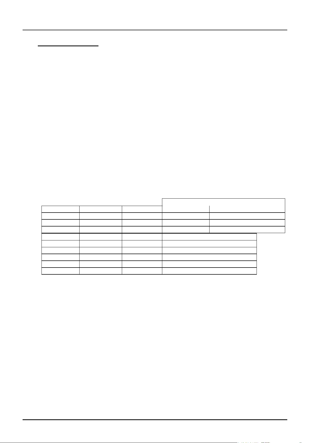
CONNECTION DETAILS
supply type
Supply
Terminal label
Cable colour
Live-Neutral
Reversible or Live-Live
1-phase
L
Brown
To live
to either power conductor
N
Blue
To neutral
to the other power conductor
PE
Green/Yellow
To earth (ground)
to earth (ground)
supply
Terminal label
Cable colour
2- or 3-phase
L1
Black
to phase 1
L2
Black
to phase 2
L3
Black
to phase 3 except 2-phase
N
Light Blue
to neutral except delta
PE
Green/Yellow
to earth (ground)
High Temperature Ovens
2.3 Electrical Connections
Connection by a qualified electrician is recommended.
All ovens covered by this manual may be ordered for single phase A.C. supply, which may be Live
to Neutral non-reversible, Live to Neutral reversible or Live to Live. Some models may be ordered
for use on a three phase supply with neutral (e.g. 380/220V) or for three phase without neutral
(delta); some for two phases out of a 3-phase + neutral supply.
Check the Oven rating label before connection. The supply voltage should agree with the voltage
on the label, and the supply capacity should be sufficient for the amperage on the label.
The supply should be fused at the next size equal to or higher than the amperage on the label. A
table of the most common fuse ratings is also given in section 8.1 of this manual. Where a supply
cable is present there are internal supply fuses; customer fusing is preferred but not essential.
Oven with supply cable: either wire directly to an isolator or fit with a line plug.
Oven without supply cable: a permanent connection to a fused and isolated supply should be made
to the internal terminals after temporary removal of the Oven back panel.
Connection by line plug: the plug should be within reach of the operator, and should be quickly
removable.
Connection to isolating switch: this should operate on both conductors (single phase) or on all live
conductors (three phase), and should be within reach of the operator.
The supply MUST incorporate an earth (ground).
4 MF16 3.09
High Temperature Ovens
3.0 OPERATION
The instructions for operating the temperature controller are given in a separate manual.
If the oven is fitted with a time switch, see also the supplementary manual MS03.
If cascade control is fitted, see the supplementary manual MS07.
If the oven has variable speed fan, air extraction or stoving and curing options, please also see the
appropriate section on the next page of this manual.
3.1 Operating Cycle
The oven is fitted with an instrument switch. The switch cuts off power to the controller(s).
The circulation fan operates when the instrument switch is switched on. In the LHT models the
case cooling fans operate when the instrument switch is on.
Connect the oven to the electrical supply.
Operate the instrument switch to activate the temperature controller. The controller becomes
illuminated and goes through a short test cycle.
Adjust the temperature controller – see the controller manual.
Overtemperature option only. If the overtemperature controller has not yet been set as required, set
it and activate it according to the instructions in the appropriate manual.
Unless a time switch is fitted and is off, the oven begins to heat up according to the controller set
point or program.
To turn the oven off, set the Instrument switch to it’s off position; the controller display will go
blank. If the oven is to be left off unattended, isolate it the electrical supply.
DO NOT switch off if the temperature is above 300°C - damage could be caused to the fan and
motor. Adjust the controller or the overtemperature controller to allow the temperature to fall.
3.2 Overtemperature Control (if fitted)
The overtemperature controller should typically be set at 15°C above the main controller. If an
overtemperature condition occurs, check the possibility that the main control system has failed.
An overtemperature condition cuts off power to the heating elements. It is indicated by a light in
the overtemperature controller flashing. To reset the condition, either allow the oven to cool, or
increase the overtemperature setting, then follow the instructions in the appropriate manual.
3.3 Explosive Vapours
The standard models are not suitable for drying or heat treatment applications where vapours are
released which are combustible or which can form explosive mixtures with air. For such
applications only use models supplied specially for the purpose.
3.4 Atmospheres (only applies to LHT and HT models)
When an optional gas inlet is fitted there is a label near the inlet saying "INERT GAS ONLY". In
practice inert or oxidising gases may be used, but not combustible or toxic gases. The oven
chambers are not gas tight, so it should be understood that gas usage may be high, and that the
chamber is likely always to contain some air. Residual oxygen levels of 1% are to be expected.
MF16 3.09 5
 Loading...