


CONTENTS
Section page
Installation, Operation &
Maintenance Instructions
1200°C - 1300°C Chamber Furnaces
GPC models
This manual is for the guidance of operators of the above Carbolite products and should
be read before the furnace is connected to the electricity supply.
Manuals are supplied separately for the furnace controller
(and overtemperature controller when fitted).
Please read the controller manuals before operating the furnace.
MF04 – 3.29
Instrument switch: when the instrument switch is operated the temperature
control circuit is energised.
Heat Light: the adjacent light glows or flashes to indicate that power is
being supplied to the elements
DANGER of electrical shock– read any warning printed by this symbol.
DANGER – hot surface. Read any warning printed by this symbol.
WARNING: all surfaces of a furnace may be hot.
DANGER – read any warning printed by this symbol.
GPC
1.0 INTRODUCTION
1.1 GPC models
This manual covers both the “laboratory” and “industrial” GPC furnaces.
The laboratory models are GPC 12/36, GPC 13/36, GPC 12/65 and GPC 13/65. These are
designed for bench mounting, but can be supplied with a stand.
The industrial models are GPC 12/131, 13/131 and GPC 12/200. These are floor standing units.
The furnaces are fundamentally similar in operation, but the industrial sizes are altogether larger
and therefore require somewhat different handling and siting.
1.2 Switches and Lights
1.3 Warning Symbols
2 MF04 3.29

GPC
2.0 INSTALLATION
2.1 Unpacking & Handling
Laboratory Models. When unpacking or moving the furnace always lift it by its base. Never lift it
by the door. Use two people to carry the furnace. Remove any packing material from the door gear
and furnace chamber before use.
Industrial Models. Use a fork lift or pallet truck to position the furnace on a level floor.
NOTE: This product contains Refractory Ceramic Fibre (better described as Alumino Silicate
Wool) for precautions and advice in handling this material see the ‘Repairs and Replacements’
section.
2.2 Siting
Place the furnace in a well ventilated area, away from other sources of heat, and on a surface
which is resistant to accidental spillage of hot materials. Do not mount the furnace on an
inflammable surface.
Ensure that there is free space around the furnace. Do not obstruct any of the vents in the control
section: they are needed to keep the controls cool.
Ensure that the furnace is placed in such a way that it can be quickly switched off or disconnected
from the electrical supply - see below.
2.3 Setting Up
The furnace is supplied with the hearth tiles supported in place by a timber batten or steel plate
held by a jacking bolt fixed through the roof chimney hole. The chimney is supplied separately.
For the industrial models the door counterbalance weights are also supplied separately.
Laboratory models. Remove the bands holding the frame to the top of the furnace case. Withdraw
the bracket with the jacking rod assembly. Remove the steel plate from the hearth tile.
Fit the supplied furnace chimney through the roof hole.
Industrial models. To remove, take off the roof panel and unscrew the bracket complete with the
jacking rod assembly.
Fit the furnace chimney before replacing the roof panel.
Fit the door counterbalance weights to the door shaft such that the locking screws lock into the
countersunk holes. Note that one of the weights has a flat surface on the boss opposite the locking
screw. This weight goes on the side by the limit switch assembly such that the plunger of the
switch is depressed when the door is opened.
2.4 Fume Removal
If the furnace is to be used to heat substances which emit fumes, then a fume extraction duct of
about 150mm inlet diameter may be placed directly above the chimney outlet. Do not make a
sealed connection to the furnace chimney as this causes excessive airflow through the chamber and
gives poor temperature uniformity.
MF04 3.29 3
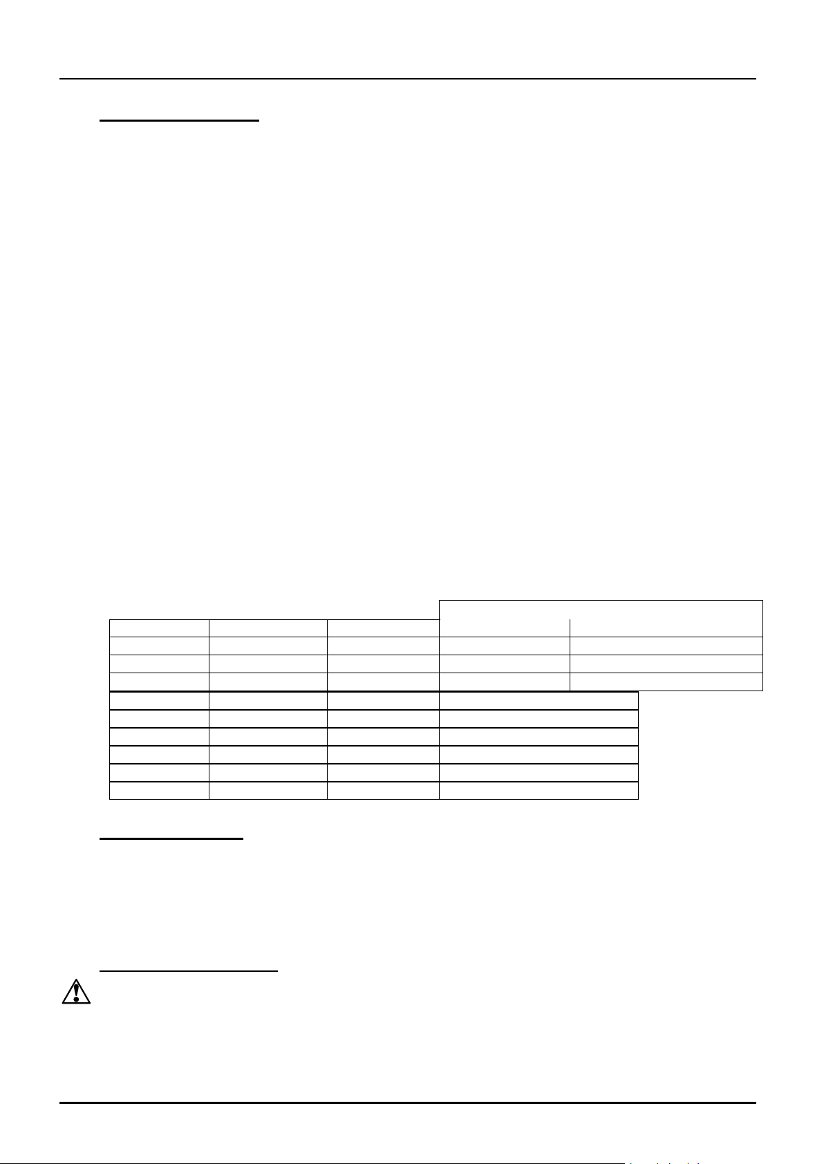
CONNECTION DETAILS
supply type
Supply
Terminal label
Cable colour
Live-Neutral
Reversible or Live-Live
1-phase
L
Brown
To live
to either power conductor
N
Blue
To neutral
to the other power conductor
PE
Green/Yellow
To earth (ground)
to earth (ground)
supply
Terminal label
Cable colour
3-phase
L1
Black
to phase 1
L2
Black
to phase 2
L3
Black
to phase 3
N
Light Blue
to neutral except delta
PE
Green/Yellow
to earth (ground)
GPC
2.5 Electrical Connections
Connection by a qualified electrician is recommended.
All GPC models have three internal circuits and are normally supplied for three phase supply. This
may be either star or delta, but a furnace must only be connected to the type and voltage of supply
for which it was made (but see 2.6). If the furnace is ordered for a single phase supply, this may be
Live to Neutral reversible or non-reversible, or Live to Live.
Access to electrical connections is by removal of the back panel (laboratory models), or removal of
the lower back panel (industrial models). The industrial models are fitted with an internal isolator;
cabling should be taken through the mesh base panel directly to the isolator or the nearby
terminals: live connections to the isolator; neutral (if present) and earth to the nearby terminals.
Check the furnace rating label before connection. The supply voltage should agree with the voltage
on the label, and the supply capacity should be sufficient for the amperage on the label.
The supply should be fused at the next size equal to or higher than the amperage on the label. A
table of the most common fuse ratings is also given in section 8.1 of this manual. Where a supply
cable is present there are internal supply fuses; customer fusing is preferred but not essential.
Furnace with supply cable: either wire directly to an external isolator or fit with a line plug.
Furnace without supply cable: a permanent connection to a fused and isolated supply should be
made to after temporary removal of the furnace back panel.
Connection by line plug: the plug should be within reach of the operator, and should be quickly
removable.
Connection to external isolating switch: this should operate on both conductors (single phase) or
on all live conductors (three phase), and should be within reach of the operator.
The supply MUST incorporate an earth (ground).
2.6 “Universal Wiring”
From Year 2000 GPC 12/36 and GPC 13/36 models can be easily rewired between 1-phase and
3-phase supplies. This applies to 3-phase+N and 3-phase delta in the ranges 380/220V–415/240V
and 208-240V, but does not apply to 3-phase star without neutral (e.g 380V).
To alter the configuration, remove the back panel and alter the wiring connections between the
supply terminal block and the EMC filters, using the appropriate diagram from section 7.6.
2.7 Voltage and Power Limit
When first starting up the furnace check the setting of the OP.Hi parameter (see controller manual)
and compare it with the data in section 8.2. If the power limit setting is incorrect for the voltage of
your supply, change it. This must be done immediately if the setting of OP.Hi is higher than it
should be.
4 MF04 3.29
GPC
3.0 OPERATION
The instructions for operating the temperature controller are given in a separate manual.
If the furnace is fitted with a time switch, see also the supplementary manual MS03.
If cascade control is fitted, see the supplementary manual MS07.
3.1 Operating Cycle
The furnace is fitted with an instrument switch. The switch cuts off power to the control circuit.
Connect the furnace to the electrical supply.
Operate the instrument switch to activate the temperature controller. The controller becomes
illuminated and goes through a short test cycle.
Close the furnace door and adjust the temperature controller – see the controller manual.
Overtemperature option only. If the overtemperature controller has not yet been set as required, set
it and activate it according to the instructions in the appropriate manual.
Unless a time switch is fitted and is off, the furnace starts to heat up. The Heat lights glow steadily
at first and then flash as the furnace approaches the desired temperature or a program setpoint.
Overtemperature option only. If the overtemperature trip operates then an indicator in the
overtemperature controller flashes, and the heating elements are isolated. Find and correct the
cause before resetting the overtemperature controller according the instructions supplied.
To turn the furnace off, set the Instrument switch to it’s off position; the controller display will go
blank. If the furnace is to be left off unattended, isolate it the electrical supply.
3.2 General Operating Notes
Heating element life is shortened by use at temperatures close to maximum. Do not leave the
furnace at high temperature when not required. The maximum temperature is shown on the
furnace rating label and on the back page of this manual.
When heating large objects, in particular poor conductors, avoid shielding the thermocouple from
the heating elements. The thermocouple is intended to sense the temperature near the heating
element, but if a large object is placed in the chamber it may record the average temperature of the
object and the elements, which can lead to overheating of the elements. Allow large objects to gain
heat at a lower temperature and then reset the controller to a temperature close to the desired
maximum.
Light weight ceramic fibre insulation can easily be marked by accidental contact. Some fine cracks
may be visible on the surface of the insulation, or may develop in the surface of the chamber due
to the progressive shrinkage of the insulation materials. Cracks are not usually detrimental to the
functioning or the safety of the furnace.
When heating materials which produce smoke or fumes, the chimney must be correctly fitted and
unobstructed. Otherwise, soot can accumulate in the chamber and could possibly cause an
electrical breakdown of the heating element.
If the furnace is used to heat materials which emit smoke or fumes, regularly heat it up to
maximum temperature for one hour without load to burn away the soot.
3.3 Use of Probes
Any metal object used to probe into the furnace chamber while the furnace is
connected to the supply must be earthed (grounded). This applies in particular to
metal sheathed thermocouples, where the sheaths must be earthed. The refractory
material of the chamber lining becomes partly conducting at high temperatures, and
the electric potential inside the chamber can be at any value between zero and the
supply voltage. Unearthed probes can cause serious electric shock.
MF04 3.29 5
 Loading...