


Contents
Section Page
1.0 Introduction 2
2.0 Installation 3
3.0 Operation 4
4.0 Maintenance 6
5.0 Repairs & Replacements 7
6.0 Fault Analysis 10
7.0 6L & 14L Circuit Diagram and Fuses 11
8.0 23L Circuit Diagram & Fuses 12
10.0 Fuses 14
11.0 Specification 14
Installation, Operation &
Maintenance Instructions
1100°C Chamber Furnaces
ELF models
This manual is for the guidance of operators of the above Carbolite products
and should be read before the furnace is connected to the electricity supply.
Please read the controller manuals before operating the furnace.
MF01 – 3.31
ELF (B)
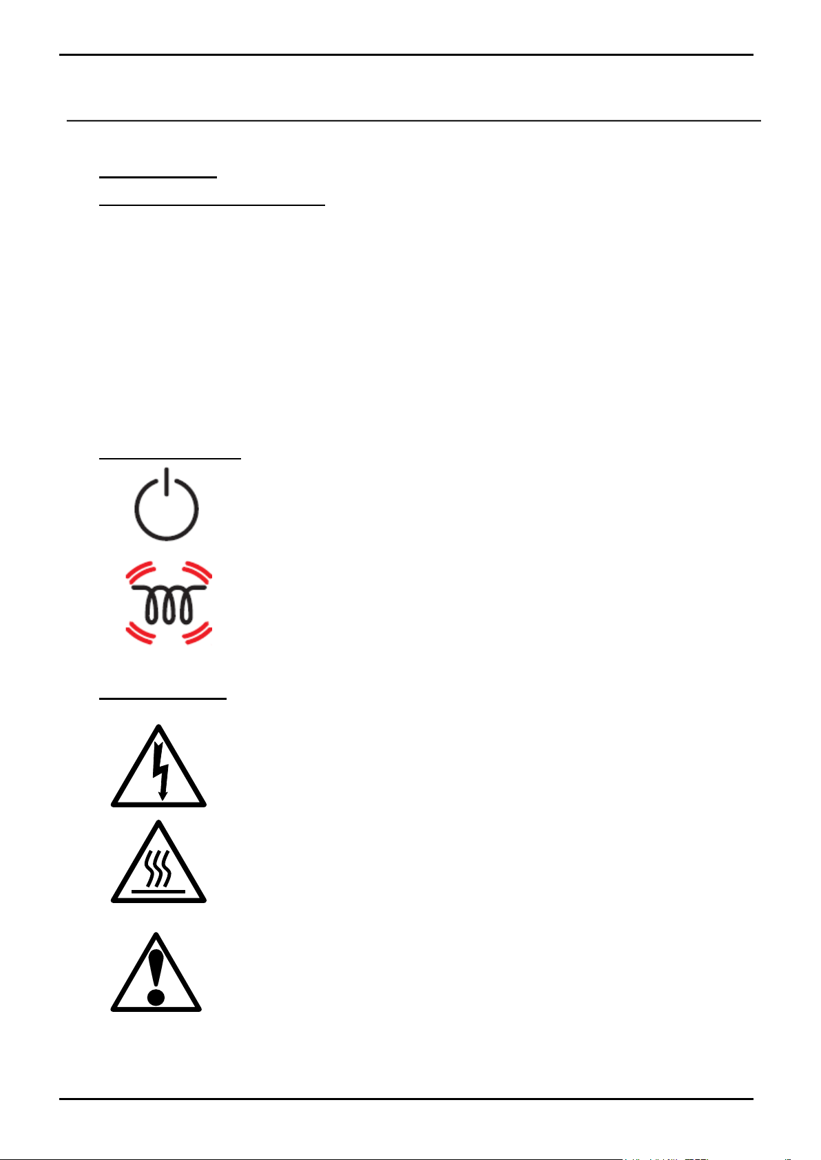
Instrument switch: when the instrument switch is operated the temperature
control circuit is energised.
Heat Light: the adjacent light glows or flashes to indicate that power is
being supplied to the elements
DANGER of electrical shock– read any warning printed by this symbol.
DANGER – hot surface. Read any warning printed by this symbol.
WARNING: all surfaces of a furnace may be hot.
DANGER – read any warning printed by this symbol.
1.0 INTRODUCTION
1.1 Models Covered by this Manual
This manual covers the Carbolite furnace models ELF 11/6B, ELF 11/14B and ELF 11/23B. The B
suffix indicates differences from earlier models, in particular that the heating element is enclosed
in an inner metal chamber, and the heating wires are partly exposed in the chamber sides and
radiate freely into the chamber. The B models were not made before mid-2001.
The B versions also allow for a simple customer adjustment to increase the air flow through the
chamber. Carbolite do not claim that this adjustment makes the furnace suitable for ashing or burnoff applications.
The B versions may be set to operate on any single-phase voltage in the range 200-240V (or 100120V to order) by correct setting of the power limit parameter in the controller.
Because of model changes it is very important when ordering spares to state the furnace serial
number or otherwise to identify the model correctly.
1.2 Switches and Lights
1.3 Warning Symbols
2 MF01 3.31
ELF (B)
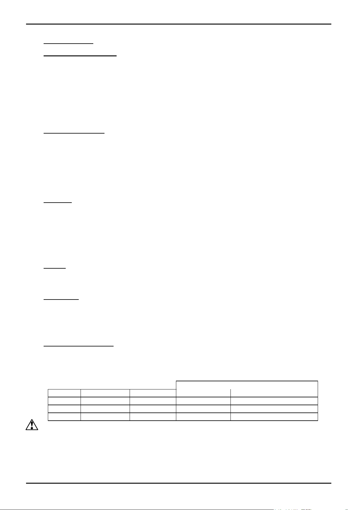
CONNECTION DETAILS
supply type
Supply
Terminal label
Cable colour
Live-Neutral
Reversible or Live-Live
1-phase
L
Brown
To live
to either power conductor
N
Blue
To neutral
to the other power conductor
PE
Green/Yellow
To earth (ground)
to earth (ground)
2.0 INSTALLATION
2.1 Unpacking & Handling
When unpacking or handling the furnace always lift it by its base. Never lift it by the door. Use
two people to unpack and carry the furnace.
Carefully remove any packing material from the furnace chamber. Avoid damaging the
surrounding insulation when removing packing materials.
NOTE: This product contains Refractory Ceramic Fibre (better described as Alumino Silicate
Wool) for precautions and advice in handling this material see the ‘Repairs and Replacements’
section.
2.2 Siting & Setting Up
Place the furnace in a well ventilated room, away from other sources of heat, and on a non-
inflammable surface that is resistant to accidental spillage of hot materials.
Ensure that there is free space of at least 50mm around the furnace. Do not obstruct any of the case
vents: they are needed to keep the controls and the case exterior cool.
Ensure that the furnace is placed in such a way that it can be quickly switched off or disconnected
from the electrical supply.
2.3 Chimney
The chimney is a short length of ceramic tubing. If it is supplied unfitted, then fit it through the
hole in the top of the furnace case.
If the furnace is to be used to heat substances that emit fumes, then a fume extraction duct of about
150mm inlet diameter may be placed directly above the chimney outlet. Do not attempt make a
sealed connection to the furnace chimney as this causes excessive airflow through the chamber and
results in poor temperature uniformity.
2.4 Hearth
The chamber floor (hearth) is supplied with a ceramic tile. This may already be in position in the
chamber. If it is packed separately, unwrap it and place it carefully on the chamber floor.
2.5 Door Vents
There is a plate fixed to the inner door panel (door plug carrier), accessible by removing the door
insulation piece. This can be positioned to open up holes in the inner door, to allow an increased
air flow in the chamber. Decide on the required position and fix the plate accordingly (see section
5.7).
2.6 Electrical Connections
Connection by a qualified electrician is recommended.
The furnace requires a single-phase A.C. supply with earth (ground), which may be Live to Neutral
non-reversible (polarised), Live to Neutral reversible (non-polarised), or Live to Live.
Check the following before connection, by reference to the furnace rating label.
Voltage range: the voltage on the label and the actual supply voltage should be in the same range –
either the range 200-240V or the range 100-120V. The furnace must not be connected to the wrong
range.
MF01 3.31 3
ELF (B)
Amps: the actual supply must be capable of supplying the required amps. It should be fused at the
next available fuse size equal to or greater than the amps on the rating label.
A supply cable is fitted to 200-240V models, but may not be to 110-120V models. If there is no
cable, remove the back panel and connect a suitably rated cable to the internal terminals.
Either wire the supply cable directly to an isolator or fit it with a line plug. The plug or isolator
should be within easy reach of the operator to permit quick disconnection of the power.
For operator safety the supply MUST incorporate an earth (ground).
3.0 OPERATION
3.1 Operating Cycle
The furnace is fitted with an instrument switch. The switch cuts off power to the controller.
Connect the furnace to the electrical supply.
Operate the instrument switch to activate the temperature controller. The controller becomes
illuminated and goes through a short test cycle.
Close the furnace door and adjust the temperature controller – see controller manual
As the furnace heats up the Heat light glows steadily at first and then flashes as the furnace
approaches the desired temperature. For further information on temperature control, see controller
manual.
To turn the furnace off, set the Instrument switch to it’s off position; the controller display will go
blank. If the furnace is to be left off unattended, isolate it the electrical supply.
3.2 General Operating Notes
Heating element life is shortened by use at temperatures close to maximum. Do not leave the
furnace at high temperature when not required. The maximum temperature for ELF models is
1100°C (2012°F).
When heating large objects, in particular poor conductors, avoid shielding the thermocouple from
the heating elements. The thermocouple is intended to sense the temperature near the heating
element, but if a large cold object is placed in the chamber it may record the average temperature
of the object and the element, which can lead to overheating of the element. Allow large objects to
gain heat at a lower temperature and then adjust the controller setpoint to a temperature close to
the desired maximum.
Materials such as case hardening compounds and other reactive salts may attack the wire elements,
causing premature failure. The insulation chamber includes a ceramic hearth that helps to protect
the insulated floor.
Note that if the door vents are open then the entry of cold air through the vents can give rise to a
cool area in the chamber.
The moulded light weight ceramic fibre insulation can easily be marked by accidental contact with
tongs etc. Some fine cracks may be visible at the front of the insulation, or may develop in the
surface of the chamber due to the progressive shrinkage of the ceramic fibres. Cracks are not
usually detrimental to the functioning of the furnace.
When heating materials that produce smoke or fumes, the chimney must be correctly fitted and
unobstructed. Otherwise, soot may accumulate in the chamber and could possibly cause an
electrical breakdown of the heating element. To prevent this, regularly heat the furnace up to
maximum temperature for one hour without load to burn away the soot.
4 MF01 3.31

ELF (B)
Light weight ceramic fibre insulation can easily be marked by accidental contact. Some fine cracks
may be visible on the surface of the insulation, or may develop in the surface of the chamber due
to the progressive shrinkage of the insulation materials. Cracks are not usually detrimental to the
functioning or the safety of the furnace.
3.3 Use of Probes
Any metal object used to probe into the furnace chamber while the furnace is
connected to the supply must be earthed (grounded). This applies in particular to
metal sheathed thermocouples, where the sheaths must be earthed. The refractory
material of the chamber lining becomes partly conducting at high temperatures, and
the electric potential inside the chamber can be at any value between zero and the
supply voltage. Unearthed probes can cause serious electric shock.
3.4 Atmospheres
When an optional gas inlet is fitted there is a label near the inlet saying "INERT GAS ONLY". In
practice inert or oxidising gases may be used, but not combustible or toxic gases. Chamber
furnaces are not gas tight, so it should be understood that gas usage may be high, and that the
chamber is likely always to contain some air. Residual oxygen levels of 1% are to be expected.
3.5 Operator Safety
The furnace incorporates a safety switch which interrupts the heating element circuit when the
door is opened. This prevents the user touching a live heating element, but also prevents the
furnace from heating up if the door is left open. The operation of this switch should be checked
periodically – see section 4.1.2.
3.6 Power Adjustment
The furnace control system incorporates electronic power limiting, which is used in some models
to compensate for voltage to achieve the same power over a range of voltage supplies. In other
models the power limit is set to 100% over all common voltages. The power limit parameter may
be accessible to the operator, but should not generally be altered.
See section 8.3 for details of power limit settings. DO NOT adjust the power to a level higher that
the design level stated: this may cause fuse to blow, and could damage the heating elements.
The power limit may be set to a lower limit if the furnace is to be used at a low temperature only:
this may give better control stability. It may set to zero to permit demonstration of the controls
without the heating elements taking power; to resume heating reset it to its standard value.
MF01 3.31 5
 Loading...