

Carbolite 3508 P1, 3508P10, 3508P25 Operating Instructions Manual
1 MC19-1.22
Operating Instructions
Temperature Controller
Type 3508
English
Ack
3508
1200
EUROTHERM
23
RUN/HOLD
RUN/HLD
OP1
°C
%
96.0
A/MAN

3508 Controller
2
MC19-1.22
Note: For the purposes of this manual the Eurotherm 3504 range is functionally identical to
the 3508 range.

3508 Controller
3
MC19-1.22
Contents
1.1 Using This Manual 4
1.2 PID Control 4
2 Basic Operation 5
2.1 Controller Layout (Home display) 5
2.2 Keys 5
3 Quick Start Guide 6
3.1 Operation as a simple controller 6
3.2 Changing the Setpoint 6
3.3 Resetting the programmer 6
3.4 Operating the current program 6
3.5 Understanding User Levels 6
4 Setting up the controller 8
4.1 Maximum output power setting 8
4.2 Customer ID. 8
4.3 Units 8
4.4 Language 8
5 Programming 9
5.1 Programming Notes 9
5.2 Holdback 9
5.3 Wait Segments 10
5.4 Program Cycling 10
5.5 Creating a Program 11
5.6 Running a Program 12
5.7 To pause (hold) a program 12
5.8 To stop and reset a program 12
5.9 To run a different program (P10 and P25) 12
5.10 Program Status 13
5.11 Power Failure Recovery 13
5.12 Alarms 14
5.13 Program Example 1 14
5.14 Program Example 2 16
6 Options 17
6.1 Digital Communications – RS232 17
6.2 Digital Communications – RS485 17
6.3 Comms Address 17
6.4 Alarm Option 18
6.5 Remote Input and Output (Analogue Communications) 18
6.6 Program segment output 18
7 Navigation Diagrams 19
7.1 Operator Level 1 - No Program Running 19
7.2 Operator Level 1 - Program Running 20
7.3 Supervisor Level 2 21
8 Controller Fault 22
8.1 Fault Code Diagnostic Table 22
9 Glossary of Terms 22

3508 Controller
4
MC19-1.22
Introduction to the Controller and Manual
1.1 Using This Manual
This manual aims to explain how to set up and operate the Eurotherm 3508 series of
controllers; it must be read in conjunction with the product main manual.
Due to the complex nature of furnace or oven control the use of technical terms throughout
this manual is unavoidable. Explanations of these terms can be found in the ‘Glossary of
Terms’ at the back of this manual.
This manual covers the operation of:
3508 P1 – Controller/Programmer
The 3508 P1 is a digital temperature controller which uses PID algorithms to give excellent
temperature control when properly set. This controller can store and run a single program of
up to 20 segments. The 3508P1 can also be used as a simple temperature controller.
3508P10 – Controller/Programmer
The 3508 P10 is a digital temperature controller which uses PID algorithms to give excellent
temperature control when properly set. This controller can store 10 programs of up to 50
segments each. Programs can be run individually or linked by a Call parameter as subprograms or to form single long programs. The 3508P10 can also be used as a simple
temperature controller.
3508P25 – Controller/Programmer
The 3508 P25 is a digital temperature controller which uses PID algorithms to give excellent
temperature control when properly set. This controller has a maximum of 500 segments or
25 programs; each program has a maximum of 50 segments. For example a 3508P25 could
store 10 programs with 50 segments or 25 programs with 20 segments. Programs can be
run individually or linked by a Call parameter as sub-programs or to form single long
programs. The 3508P25 can also be used as a simple temperature controller.
The 3508 does not contain a real-time calendar.
1.2 PID Control
The 3508 series of controllers use PID (Proportional Integral Derivative) temperature
control. This type of control uses a complex mathematical control system to adjust the
power being sent to the elements and hold the furnace or oven at the desired temperature.
Basic Operation
5 MC19-1.22
2 Basic Operation
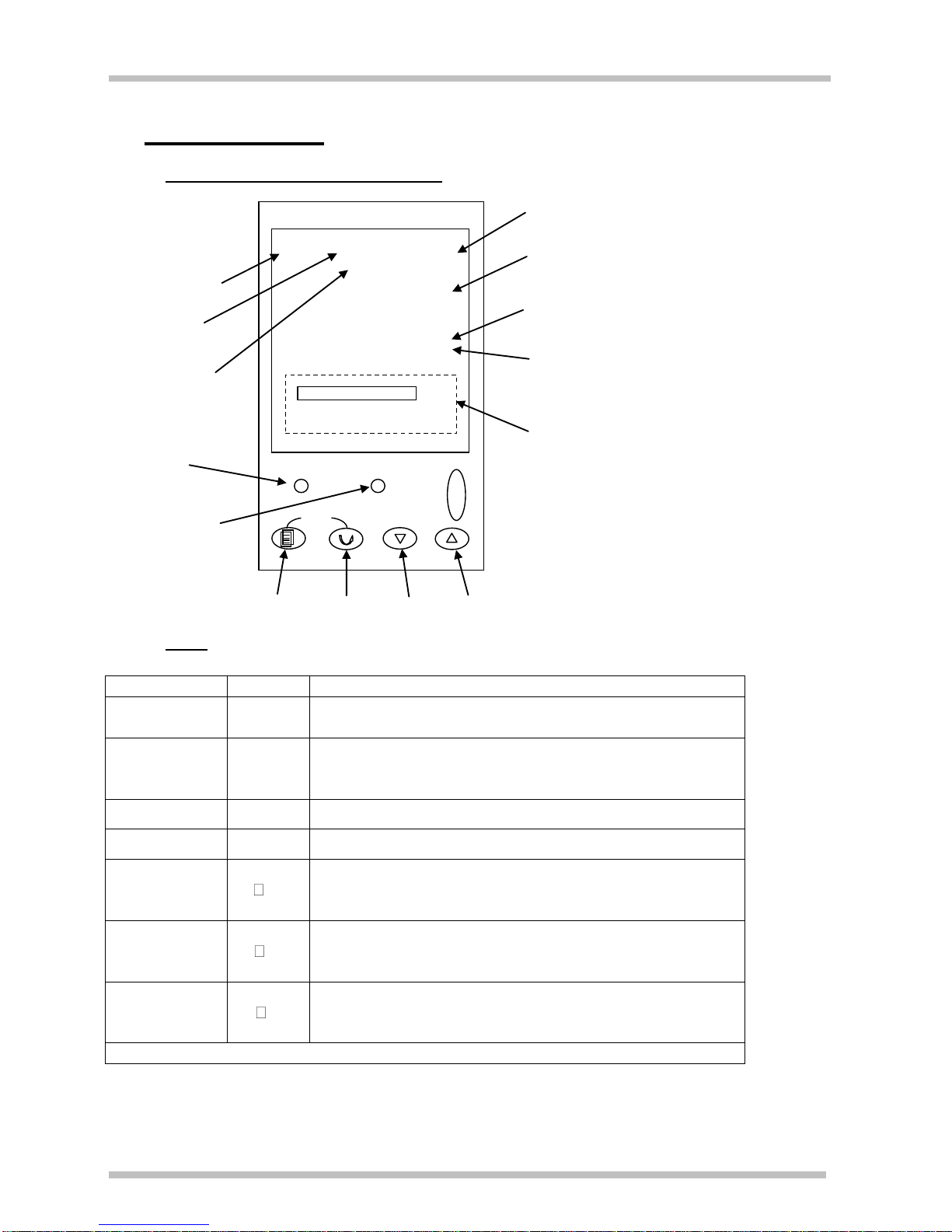
2.1 Controller Layout (Home display)
2.2 Keys
A/Man
-
Disabled
RUN/HOLD
-
Runs, Holds or Resets the current program. Hold
down for 3 seconds to Reset.
Page key
Scrolls through the page headings. Hold down for 3
seconds to access further levels, pass codes are
required.
Scroll key
Scrolls through parameters listed on pages.
Arrow keys
&
Adjust parameter values
Page and
scroll
together
+
Press together to return to the home display or to
acknowledge an alarm
Page and up
arrow
together
+
Press together quickly to scroll back up the page
headings
Scroll and up
arrow
together
+
Press together quickly to scroll back up a parameter
list
Pressing any other combination of keys together has no effect
Note: If no keys are pressed for 1 minute, the display returns to Home.
Power output
indicator
Measurement units
Measured temperature
Program Setpoint temperature (PSP)
when a program is running
Power output
percentage
Program status
indicators.
Setpoint temperature (SP)
when basic controlling
Not used
Page
Scroll
Down
Up
Runs, Holds,
Resets the current
program
OP1
°C
23
1200
%
96.0
RUN HLD
EUROTHERM
A/MAN
RUN/HOLD
3508
Ack
ALM
Alarm indicator

Quick Start Guide
6 MC19-1.22
3 Quick Start Guide
3.1 Operation as a simple controller
When switched on the controller goes through a short test routine and then shows the
measured temperature. Below it is shown the setpoint temperature (SP) and percentage of
power output.
3.2 Changing the Setpoint
Press up down to select the required SP. If the SP is higher than the measured
temperature, the OP1 indicator will illuminate at the top of the display, indicating that the
controller is calling for power (giving an output).
The controller will immediately attempt to reach the set temperature and maintain it.
3.3 Resetting the programmer
To reset the programmer to simple controller mode, press RUN/HOLD for 2 seconds.
3.4 Operating the current program
To avoid unwanted heating at the end of a program, set the SP temperature to zero
before running a program.
Ensure the programmer is reset to simple controller mode before starting a program,
by pressing RUN/HOLD for 2 seconds.
To start the program, press RUN/HOLD twice, RUN will light up on the display.
The displayed Program Setpoint (PSP) follows ramps, dwells and steps as the program
runs. The SP temperature of the controller does not apply when a program is running.
To pause the program, press RUN/HOLD.
To stop the program and return to simple controlling (reset), press RUN/HOLD for 2
seconds.
When the program ends, the programmer will either:
Automatically reset to operation as a simple controller.
Dwell at the last temperature of the program (with the RUN indicator flashing), until
the operator presses RUN/HOLD for 2 seconds to manually reset, or presses
RUN/HOLD once to restart the program.
Turn power to the elements down to zero.
3.5 Understanding User Levels
There are two levels in the controller; Level 1(Operator) and Level 2 (Supervisor).
Level 1 (Operator) is for the day-to-day operation of the controller and parameters are not
protected by a security code. There are 3 pages at this level. Page 1, Customer Identity,
can only be altered in level 2. Page 2 shows the current program status. Page 3 is for
writing and viewing programs.
Level 2 (Supervisor) provides access to additional parameters and access to these is
protected by a security code. A further 4 pages are accessible in this level as follows;
Customer identity, Control Output Hi percentage, Units.
To Enter Level 2:
1. Press and hold page for 3 seconds. The display will show “Access Goto Level 1”

Quick Start Guide
7
MC19-1.22
2. Press up to select level 2. After a short pause the display will show “Access Pass
code”.
3. Press up or down to enter the pass code 9, Pass is momentarily displayed. After
a short pause the display will return to home, the controller is now in level 2.
When Level 2 operations have been completed the supervisor must return to Level 1
manually. It is not necessary to enter a code when going from a higher level to a lower level.
To Return to Level 1:
1. Press and hold page for 3 seconds. The display will show “Access Goto Level 2.
2. Press down to go to level 1. After a short pause the display will revert to home, the
controller is now in level 1.

Quick Start Guide
8 MC19-1.22
4 Setting up the controller
Before using the controller (or during its lifetime) certain parameters may have to be set,
depending on specific requirements. To do this the Controller must be set to supervisor
Level 2, see section 3.5.
4.1 Maximum output power setting
Press page until Control Output Hi is displayed. Press up or down to adjust the value.
Depending on the furnace or oven model, the maximum power output setting may be
accessible or locked.
For Silicon Carbide heated furnaces the parameter is accessible to allow compensation for
element ageing. Refer to the product manual for details.
In many models the maximum power output setting depends on the supply voltage, refer to
the product manual for details.
4.2 Customer ID.
A furnace or oven identity number can be entered if required. This may be used to identify
one of many units, for production or quality control systems.
Press page until Customer Identity is displayed. Press up or down to select a number.
4.3 Units
Press page until Units is displayed. Press up or down to select:
C Celsius
F Fahrenheit
K Kelvin
4.4 Language
The text on the 3508 can be shown in different languages, this can only be set at the factory
and therefore must be specified at the time of placing an order.
 Loading...