

Carbine Plus 6900 Installation Manual

R
Automotive Security
Installation
Manual
Model: PLUS-6900
For Technical Assistance, please call (800) 638-3600,
or visit www.magnadyne.com
This device complies with part 15 of the FCC rules. Operation is subject to the following two conditions:
(1) This device may not cause harmful interference; and
(2) This device must accept any interference received, including interference that may cause undesired operation.
Note: The manufacturer is not responsible for any radio or TV interference caused by unauthorized modifications to this
equipment. Such modifications could void the user’s authority to operate the equipment.

Table of Contents
Installer Warnings . . . . . . . . . . . . . . . . . . . . . . . . . . . . . . . . . . . . . . . . . . . . . . . . . . . . . . . . . . . . . . . . . . 2-3
Component Placement . . . . . . . . . . . . . . . . . . . . . . . . . . . . . . . . . . . . . . . . . . . . . . . . . . . . . . . . . . . . . . . 3
Wiring Harness Quick Reference . . . . . . . . . . . . . . . . . . . . . . . . . . . . . . . . . . . . . . . . . . . . . . . . . . . . . . . 3-5
Wiring
Starter and Power Harness Wiring . . . . . . . . . . . . . . . . . . . . . . . . . . . . . . . . . . . . . . . . . . . . . . . . . . . 5-7
Door Lock Output Wiring . . . . . . . . . . . . . . . . . . . . . . . . . . . . . . . . . . . . . . . . . . . . . . . . . . . . . . . . . . . 7-10
Accessory Alarm and Remote Start Wiring . . . . . . . . . . . . . . . . . . . . . . . . . . . . . . . . . . . . . . . . . . . . . 11-16
Transmitter Programming . . . . . . . . . . . . . . . . . . . . . . . . . . . . . . . . . . . . . . . . . . . . . . . . . . . . . . . . . . . . 17
Alarm Feature Programming . . . . . . . . . . . . . . . . . . . . . . . . . . . . . . . . . . . . . . . . . . . . . . . . . . . . . . . . . . 17-21
Remote Start Feature Programming . . . . . . . . . . . . . . . . . . . . . . . . . . . . . . . . . . . . . . . . . . . . . . . . . . . . 21-22
Engine Crank Detection Programming . . . . . . . . . . . . . . . . . . . . . . . . . . . . . . . . . . . . . . . . . . . . . . . . . . . 23-25
Remote Start Shutdown Diagnostics . . . . . . . . . . . . . . . . . . . . . . . . . . . . . . . . . . . . . . . . . . . . . . . . . . . . 25
Safety Testing Your Installation . . . . . . . . . . . . . . . . . . . . . . . . . . . . . . . . . . . . . . . . . . . . . . . . . . . . . . . . 25
Shock Sensor Test Mode . . . . . . . . . . . . . . . . . . . . . . . . . . . . . . . . . . . . . . . . . . . . . . . . . . . . . . . . . . . . . 26
Return to Factory Default Settings . . . . . . . . . . . . . . . . . . . . . . . . . . . . . . . . . . . . . . . . . . . . . . . . . . . . . . 27
Wiring Diagram . . . . . . . . . . . . . . . . . . . . . . . . . . . . . . . . . . . . . . . . . . . . . . . . . . . . . . . . . . . . . . . . . . . . 28
Installer Warnings
• Due to the complexity of this system, installation must be performed by a qualified professional installer ONLY.
This remote start and alarm system is NOT a “Do It Yourself” product.
• This remote starter and alarm system is designed to be installed on fuel-injected gasoline or diesel vehicles with
an automatic transmission ONLY. Installation of this system on a vehicle with a manual transmission (Stick
Shift) is dangerous and is contrary to its intended use.
• This system must be installed and wired through a safety switch so it will not start the engine while in any
forward or reverse gear. This is normally accomplished by connecting the system's provided safety wire to the
vehicle's electronic Neutral Safety switch located on the transmission shifter.
• Some automatic transmission vehicles may have a mechanical-type park safety lock system instead of electrical
safety switch. This mechanical-type system does not interrupt the starter circuit when the transmission is in any
gear and does not offer the 100% level of safety required for remote starting purposes. The next best safety
connection point on this type of vehicle would be the vehicle parking brake switch. This requires the user to set
the parking brake prior to activating the remote starting system.
• Once you install this system, you must verify that the vehicle will not start in any forward or reverse gear,
regardless of the type of vehicle.
• Do not install any component near the brake, gas pedal or steering linkage.
• Some vehicles have a factory-installed transponder immobilizer system that can severely complicate the
installation. There is a possibility that this system can not be installed on some immobilizer-equipped vehicles.
• Most vehicles have an SRS air bag system. Use extreme care to not probe any of the wires of the SRS system.
Disconnect the vehicle (+) or (-) battery cable before installing this system on the vehicle.
• Use conventional crimp-lock type connectors on all low current wiring connections. Poor wiring, i.e. taped
joints, will introduce unreliability into the remote start and alarm system and may result in false alarms,
incorrect or failed operation.
2
Installer Warnings (continued)
HC1 6-Pin Remote Start Harness
• All wires that operate at currents higher than 10A should be soldered to ensure a long-lasting connection.
• Install wiring neatly under carpets or behind trim to prevent possible damage to wires.
• For dealer technical assistance, please call (800) 638-3600 or visit www.magnadyne.com.
Component Placement
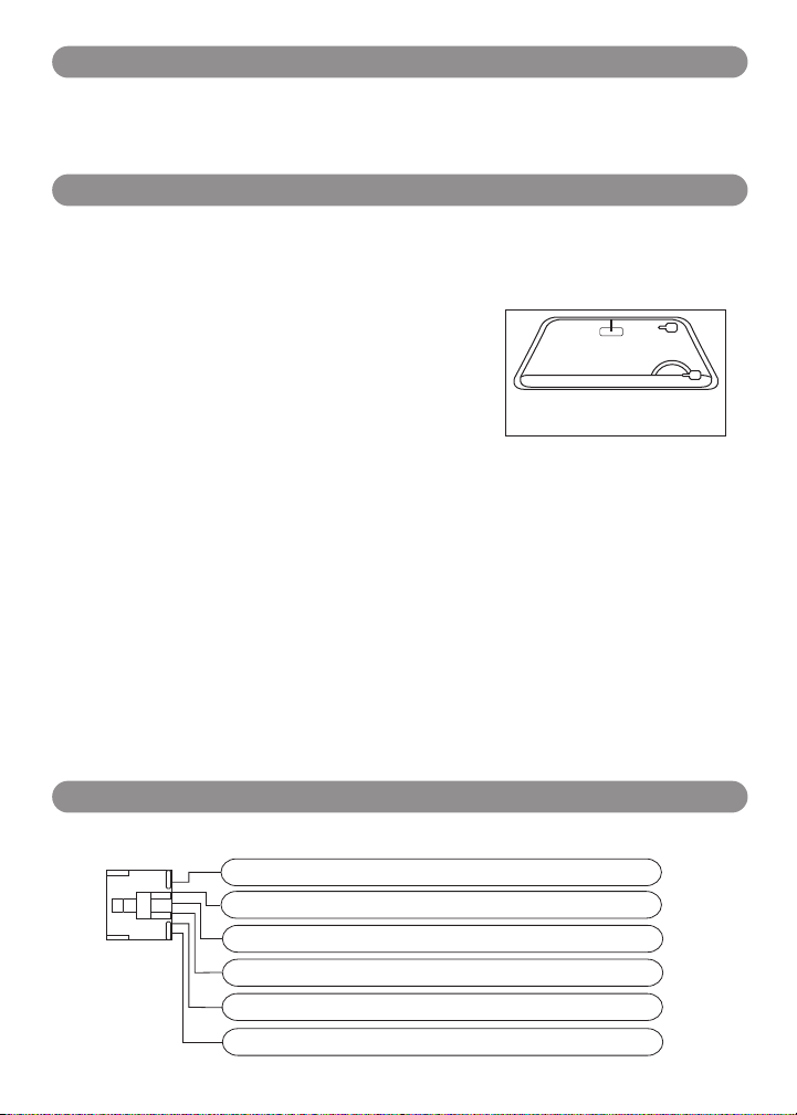
Windshield Receiver/Antenna
• The combination windshield receiver/antenna mounts on the windshield (inside).
• We suggest you mount it on the lower left-hand side of the windshield.
Warning! Do not mount in such a manner that it obstructs the driver’s view.
• The receiver/antenna whip can be vertical or horizontal.
1. Remove the protective tape backing.
2. Carefully align the receiver/antenna and apply to windshield.
3. Route the black connecting cable behind the trim and connect to
receiver/antenna.
4. Connect the other end to the control module.
Dual-Zone Shock Sensor
Select a mounting location within the passenger's compartment or trunk. Do not mount in the engine
compartment or in any location where it will get wet, greasy or will be subject to heat, whether direct or indirect.
To achieve the best overall level of protection, select a mounting location that is centrally located in the vehicle.
It will be necessary for the shock sensor to be somewhat accessible to make the correct sensitivity adjustment.
The mounting surface should be as flat as possible for best sensitivity. The sensor can be mounted in any
position as long as it is mounted solidly.
Valet Switch
Select a mounting location for the switch that is easily accessible to the driver of the vehicle. The switch does
not have to be concealed, however, concealing the switch is always recommended, as this provides an even
higher level of security to the vehicle. For best results, mount the valet switch in a hidden but accessible
location. Route the valet switch wires to the control module.
LED Status Indicator
The LED indicator status should be mounted in a highly visible area. Leave at least 6mm of space behind the
mounting location for LED housing. Once a suitable location is chosen, drill a 1/4" hole. Run the LED wires
through the hole, then press the 2-pin LED housing into the place. Route the LED wires to the control module.
Mount the antenna horizontally
for best reception.
Harness Quick Reference
Violet Remote Starter Output
Red +12VDC Battery Input #1
Red +12VDC Battery Input #1
Yellow +Ignition 1 Output
Brown +ACC / Heater - Air Conditioner Output
Pink +Ignition 2 / ACC 2 Output
3
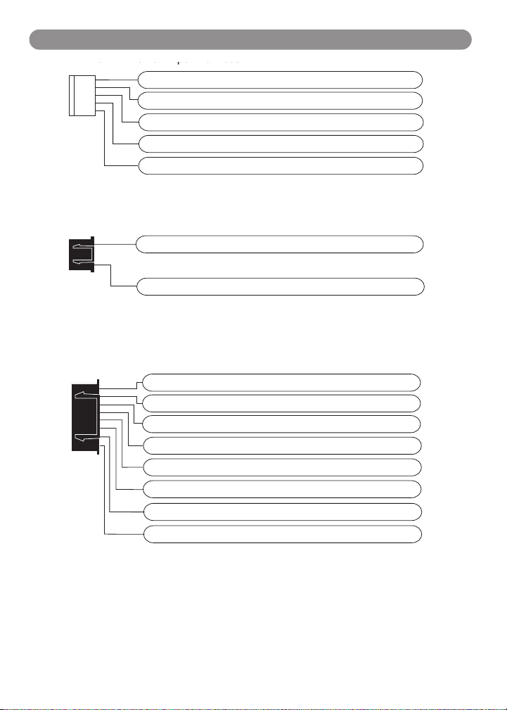
HC8 8-Pin Accessory Harness
5-Pin Power Input Harness
HC3
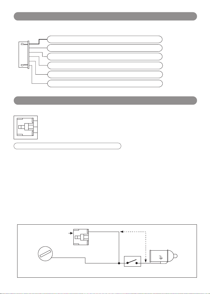
Harness Quick Reference (continued)
Red/White Parking Light Relay Input
White Parking Light Relay Output
Black Chassis Ground
Brown (+) Programmable Output (Siren Default)
Red +12VDC Battery Input
3-Pin Door Lock Harness
Blue (-) Unlock / (+) Lock Output
Green (-) Lock / (+) Unlock Output
Blue (-) Hood/Trunk Alarm Pin Input
Green (-) Common Door Pin Input
Violet (+) Common Door Pin Input
White/Blue (-) AUX Start and Turn Off Input
Gray (-) Remote Start Hood Pin Safety Input
Black/White (-) Neutral Safety Switch Input
Brown (+) Brake Switch Input
Violet/White Tach Input
4
Harness Quick Reference (continued)
HC6 6-Pin Accessory Harness
"ACC"
White (-) Programmable Output (Dome Lt - Default)
Pink (-) Ignition #3 Output
Violet/Black (-) Programmable Channel #4 Output
Red/White (-) Channel #3 Output (Trunk Release)
Light Brown (-) Programmable Output (Horn- Default)
Orange (-) Ground When Armed Output
Wiring
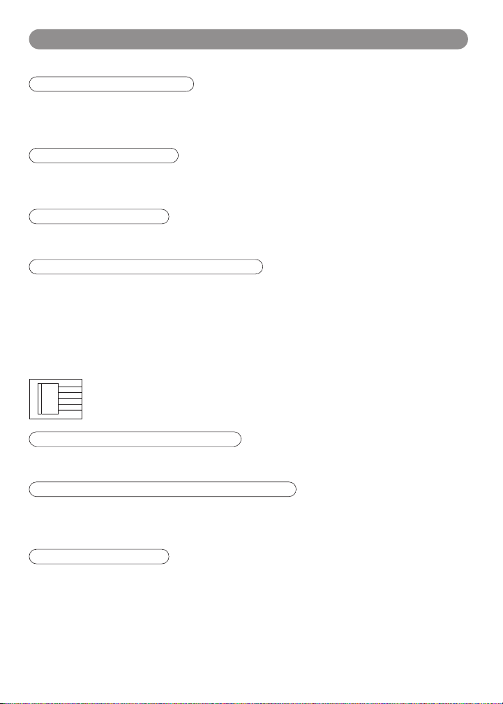
HC1: White 6-Pin High Current Remote Starter Harness
The method that the remote starter uses to start the vehicle is a duplicate of the ignition switch
function. Below is an explanation of the 3 basic functions of the ignition switch. Since this
installation will require analysis of the ignition switch functions, it is recommended that you
make the three connections below at the ignition switch harness directly.
Violet Wire: Starter Output
Careful consideration for the connection of this wire must be made to prevent the vehicle from starting while in
gear. Understanding the difference between a mechanical and an electrical Neutral Start Switch will allow you to
properly identify the circuit and select the correct installation method. In addition, you will realize why the
connection of the safety wire is required for all mechanical switch configurations.
WARNING! Failure to make this connection properly can result in personal injury and property damage.
In all installations, it is the responsibility of the installing technician to test the remote start unit and assure that
the vehicle can not start via RF control in any gear selection other than park or neutral.
In both mechanical and electrical neutral start switch configurations, the connection of the “Violet” wire will be
made to the “Starter Side” of the low current start solenoid wire at the ignition switch. This wire must have +12
volts when the ignition switch is turned to the “START” (crank) position only. Cut the starter wire and connect
the violet wire to the Starter Side of the cut wire. DO NOT connect the violet wire to the starter side of a
mechanical neutral safety switch. Failure to connect the violet wire to the ignition switch side of the neutral
safety switch can result in personal injury and property damage (see Neutral Start Safety Test for further
details).
6-Pin
White Connector
"OFF" "ON"
"START"
Violet Wire
Neutral Safety
Switch
Closed in Park
or Netral Only
Do not make the
Violet wire
connection
like this
Starter
5
Wiring (continued)
HC1: White 6-Pin High Current Remote Starter Harness (continued)
Red Wires (2): +12V Power Input
Remove the two 20A fuses prior to connecting these wires and do not replace them until the harness has been
plugged into the control module. These wires are the source of current for all the circuits the relay harness will
energize. They must be connected to a high current source. Connection to 12V battery terminal is recommended.
Yellow Wire: Ignition 1 Output
Connect the yellow wire to the ignition 1 wire from the ignition switch. The ignition wire should receive
+12 volts when the ignition key is in the “ON” or “RUN” and “START” or “CRANK” position. When the ignition is
turned “OFF”, the ignition wire should receive “0” voltage. The yellow wire must be connected.
Pink Wire: Ignition 2 Output
Some vehicles have 2 ignition wires that must be powered. Connect the pink wire to the ignition 2 wire from the
ignition switch. No connection required on vehicles without second ignition.
Brown Wire: Accessory Output, Heater/AC Output
Connect the brown wire to the accessory wire that powers the climate control system. An accessory wire will
show +12 volts when the ignition switch is turned to the “ACCESSORY” or “ON” and “RUN” positions; it will
show 0 volts when the key is turned to the “OFF” and “START” or “CRANK” position. There will often be more
than one accessory wire in the ignition harness. The correct accessory wire will power the vehicle’s climate
control system. Some vehicles may have separate wires for the blower motor and the air conditioning
compressor. In such cases, it will be necessary to add a relay to power the second accessory wire.
HC2: White 5-Pin Power Harness
Red/White Stripe: Parking Light Relay Input
The red/white wire has already been assembled to work with a +12 volt switched parking light system (most
vehicles). For vehicles with ground-switched parking-light activation, cut this wire and connect it to ground.
White Wire: Parking Light Relay Output, + or - Selectable
Connect the white wire to the parking light wire coming from the headlight switch. Do not connect the white
wire to the dashboard-lighting dimmer switch (damage to the dimmer will result). The limitation of the white
wire is 10 amp maximum. Do not exceed this limit or damage to the alarm and parking relay will result.
Black Wire: System Ground
This is main ground connection of the alarm module. Make this connection to a solid section of the vehicle
chassis. Do not connect this wire to any existing ground wires supplied by the factory wire loom; make the
connection to the vehicle’s chassis directly.
6
Wiring (continued)
Fuse
Connector
3 Wire Ground Trigger Door Lock System
To Door Lock
Control Relays
Mini Connector
3 Wire Positive Trigger Door Lock System
To Door Lock
Control Relays
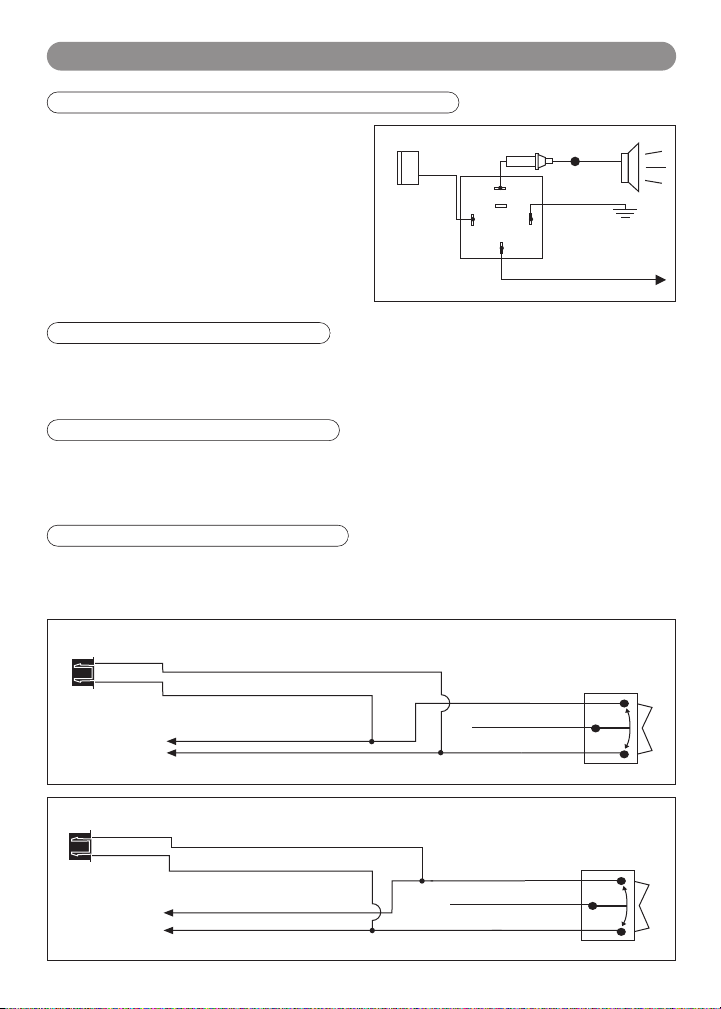
Brown Wire: (+) Programmable Output - Siren Default Setting
By default, the brown wire is the positive (+) output
connection for the siren. Current capacity is 2 amps.
Make connection to the (+) red wire from the siren.
Connect the (-) black wire coming from the siren to a
good chassis ground.
Option: (+) Horn Output (See “Alarm Feature
Programming” to change the function to horn)
Connect this wire to the existing vehicle’s horn relay
trigger. Some vehicle horn systems may be (-) trigger
and a relay will need to be added for proper operation
White
5-Pin
Brown
Wire
87
87a
86
30
To Horn
To Ground
85
+12V or Ground
Depending on
System Requirements
as shown.
Red Wire: System Power, +12V Constant
The “Red” wire supplies power to the system. Connect this wire to a constant +12 volt source.
HC3: Black 3-Pin Door Lock Harness
Blue Wire: (+/-) Door Lock/ Unlock Control
If the door lock control system on the vehicle is (-) type, connect the blue wire to the unlock wire from the door
lock switch. If the door lock control system on the vehicle is (+) type, connect the blue wire to the lock wire
from the door lock switch.
Green Wire: (+/-) Door Lock/ Unlock Control
If the door lock control system on the vehicle is (-) type, connect the green wire to the lock wire from the door
lock switch. If the door lock control system on the vehicle is (+) type, connect the green wire to the unlock wire
from the door lock switch.
Blue Wire: Connect to Unlock
Black 3-Pin
Green Wire: Connect to Lock
Blue Wire: Connect to Lock
Black 3-Pin
Mini Connector
Green Wire: Connect to Unlock
(-) Lock Out
Ground Input
(-) Unlock Out
(+) Lock Out
+12 Volts Input
(+) Unlock Out
Lock Control
Switch
Lock Control
Switch
7
Wiring (continued)
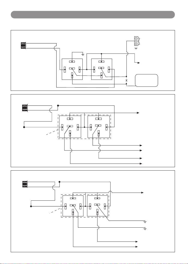
5 Wire Ground at Rest Door Locking Systems
Note:
must be connected to +12V
Newly Installed Power Door Lock Motors
To Ground
Door Lock Motors
Mercedes Door Lock Activation
Unlock
B+
HC3: Black 3-Pin Door Lock Harness
Blue Wire: Unlock
Green Wire: Lock
Black 3-Pin
Mini Connector
Blue Wire
Green Wire
Black 3-Pin
Mini Connector
Black Wire: Unlock
ALA-DL1
Relay Pack
Orange wire from ALA-DL1
Lock
87
87A
85
30
Red Wire: Lock
87
87A
85
86
30
86
Unlock
(continued)
87
++
87A
85
87
87A
85
+
86
86
30
White Wire: Lock
Brown Wire: Unlock
Blue Wire: Unlock
Green Wire
Cut
Violet Wire
Green Wire: Lock
Door Lock
Switch
Lock
To +12 Volts
(Battery +)
Door Lock
Compressor
To +12 Volts
(Battery +)
To Power
Lock Switch
To Power
Lock Motors
Blue Wire
Green Wire
Black 3-Pin Connector
8
Black Wire: Unlock
ALA-DL1
Relay Pack
Note: Orange wire from ALA-DL1
must be connected to +12V
Red Wire: Lock
87
87A
85
86
30
Violet Wire
87
87A
85
86
30
White Wire
To +12 Volts
(Battery +)
Brown Wire
Green Wire: Lock
Blue Wire: Unlock
To Newly
Installed Power
Wiring (continued)
White 6-Pin Mini
White Wire Lock
Red Wire
Mini Connector
Blue Wire
Note:
HC3: Black 3-Pin Door Lock Harness
(continued)
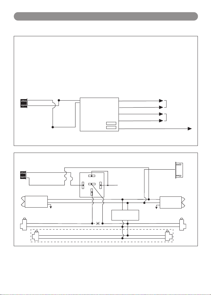
One Wire Multiplexing Door Locking Systems
Some vehicles (Chrysler, Mazda, Ford Probe and others) use one wire to lock and unlock the doors.
Example: When the door lock controller sees a signal through a resistor, it will unlock. If a signal is received
without a resistor, the doors will lock. Some use 2 resistors, one for lock and one for unlock. We have
developed patented plug-in fuse resistors for this application. Simply remove the fuse from our door lock
module and replace with correct resistor value fuses that matches the vehicles door lock switch.
Wiring:
1. Connect both the green (lock) and the blue (unlock) wires to the vehicle's one wire lock/unlock wire.
2. Connect our violet polarity input wire to +12v or to ground, to match vehicles door lock polarity.
3. The white and the brown wires will not be used.
Green Wire
Black 3-Pin
Black Wire
ALA-DL1
Lock Fuse 1
Unlock Fuse 2
Brown Wire Unlock
Green Wire Lock
Blue Wire Unlock
Violet Wire To +12 Volts Constant
To Power
Lock Switch
To Power
Lock Motors
Orange wire from ALA-DL1 must be connected to +12V.
Unlock Driver's Door First for 3-Wire Negative Door Lock Systems
Blue Wire
Green Wire
Driver's Door
Switch
To +12V or Ground
Driver's Door
Lock
Unlock
Unlock Wire
87
87A
85
ALA984H
86
30
Relay
Lock
Door Lock Relay
Cut
Control Module
+12V
Unlock
Connector
White Wire
Passenger's
Door Switch
To +12V or Ground
Passenger's Door
Rear Doors
9
 Loading...