

Page 1

Vehicle Security
INSTALLATION
MANUAL
R
© Copyright 1999 Magnadyne Corporation
Model: PLUS-5000
For Technical Assistance (800) 638-3600
For Fax on Demand Technical Assistance (800) 994-9977
(Must be a Registered Dealer to Use Fax on Demand System)
Page 2

Index
Step 1: Component Installation . . . . . . . . . . . . . . . . . . . . . . . . . . . . . . . . . . . . . . . . . . . . . . . . 2-3
Step 2: 10-Pin Main Harness Installation . . . . . . . . . . . . . . . . . . . . . . . . . . . . . . . . . . . . . . . . . 3-4
Step 3: 5-Pin Power Harness Installation . . . . . . . . . . . . . . . . . . . . . . . . . . . . . . . . . . . . . . . . 4-5
Step 4: DIP Switch Programming . . . . . . . . . . . . . . . . . . . . . . . . . . . . . . . . . . . . . . . . . . . . . . . 5
Step 5: Optional Accessory Connections . . . . . . . . . . . . . . . . . . . . . . . . . . . . . . . . . . . . . . . 6-11
Step 6: Transmitter Programming . . . . . . . . . . . . . . . . . . . . . . . . . . . . . . . . . . . . . . . . . . 12-13
Step 7: Remote Feature Programming . . . . . . . . . . . . . . . . . . . . . . . . . . . . . . . . . . . . . . . . 14-15
Step 8: Multiple Car Programming . . . . . . . . . . . . . . . . . . . . . . . . . . . . . . . . . . . . . . . . . . . . 16
Step 9: General Testing . . . . . . . . . . . . . . . . . . . . . . . . . . . . . . . . . . . . . . . . . . . . . . . . . . . . 16
Step 10: Speciality Feature and Optional Equipment Testing . . . . . . . . . . . . . . . . . . . . . . . . 16-19
Specifications . . . . . . . . . . . . . . . . . . . . . . . . . . . . . . . . . . . . . . . . . . . . . . . . . . . . . . . . . . . 19
Wiring Diagram . . . . . . . . . . . . . . . . . . . . . . . . . . . . . . . . . . . . . . . . . . . . . . . . . . . . . . . . . . 20
Warning ! Do not plug the 10-pin or 5-pin wire harness into the alarm control module before you begin
installing the alarm. The wire harnesses must be plugged into the alarm control module after all
connections are made. Failure to follow this procedure could cause some confusion with transmitter
operation and or alarm function operation.
The PLUS-5000 security system ia packaged 3 different ways for maximum flexibility. Even though the
system is packaged 3 different ways they all contain the same module and installation harnesses. The
following is how each model number is packaged:
PLUS-5000: 5000 Alarm Module with no transmitters and no siren.
PLUS-5000S: 5000 Alarm Module with (2) standard 2-button transmitters and a siren.
PLUS-5000C: 5000 Alarm Module with (2) 4-button code-hopping transmitters and a siren.
Step 1: Component Installation
Mounting the Control Module:
Find a suitable location to secure the alarm control module within the passengers compartment of the
vehicle. Never mount the alarm control module in the engine compartment or in the trunk. In addition,
never mount the alarm control module in the direct path of the heater. Secure the alarm control module
by using wire ties or drill two 1/8” holes and secure the module to the frame of the vehicle with the
screws provided.
Mounting the Siren: (Option on PLUS-5000 Packaging)
Find a suitable location in the engine compartment to secure the siren. Select a location that provides a
direct sound path to the ground for maximum siren output. Use the self tapping screws provided and
secure the siren. Connect the black wire coming from the siren to the frame of the vehicle. In many
cases, you can ground the black wire to one of the screws used to secure the siren. Run the remaining
brown wire through the fire wall to the location of the alarm control module.
Installing Hood/ Trunk Pin Switches:
Provided with the alarm kit is one pin switch and one mounting bracket. To install the switch either in the
truck or under the hood, find a suitable location where the switch will make contact with the hood or
trunk lid and will not get wet. Use the bracket provided or drill a 1/4” hole in the desired location.
2
Page 3
Step 1: Component Installation (Continued)
Mounting the LED/Valet Switch Holder:
Their are two options for mounting this item.
1. The LED can be removed from the holder and mounted in a separate location. The holder would then
be mounted with the valet switch socket facing the driver.
2. The holder can be mounted with the LED facing the driver and the valet switch socket will face the fire wall.
Select a suitable location for the holder where it will not obstruct the normal operation of the vehicle. Use
the holder as a template and drill two 1/8” holes. Secure the holder to it’s mounting location with two
screws.
Installing the Alarm Status LED: (Only Applies if LED is Not Located in the LED/Valet
Switch Holder)
Find a suitable location for the LED and drill a 5/16” hole in the desired location. Feed the 2-pin plug
through the hole and press the body of the LED into place. Run the LED wires to the location of the alarm
control module.
Step 2: 10-Pin Main Harness Installation
The main wire harness contains 8 wires which all have a specific purpose. Follow the wiring
recommendations enclosed for each wire. Wires not used should be released from the harness connector
or taped off to prevent accidental shorting. Included with the 10-pin wire harness are two loose wires, an
orange wire and a white wire with black stripe. See main harness and power harness wiring instructions
for these two loose wires.
Main Harness
Vacant Sockets
First Vacant Socket (Located in the 1st Position)
Second Vacant Socket (Located in the 8th Position)
First Vacant Socket:
See Optional Accessory Connection for proper wiring. (Page 10-11)
(For Use with ALA-RPT Relay Pack Only)
Gray Wire: (Pulsed Ground for Car Horn)
The gray wire is a pulsed ground output designed to activate the vehicle’s existing car horn system in
place of or in addition to a siren sounding device. Connect the gray wire to the negative trigger wire on
the vehicle’s horn relay.
WARNING! Maximum output of this wire is 300mA. Horn systems requiring positive voltage or more than
300mA to trigger the horn relay will require an additional relay to increase current capabilities.
Blue Wire with White Stripe: (Channel #3 Output)
Connect the blue/white wire to the device that will be operated from channel #3 of the alarm system. The
blue/white wire has a current capacity of 300mA “maximum”. This output is activated by pressing down
button #3 and holding it. The blue/white wire will provide a grounded signal as long as button #3 on the
transmitter is held down.
3
Page 4

Step 2: 10-Pin Main Harness Installation (Continued)
Brown Wire: (Siren + Output)
Connect the brown wire to the positive wire from the siren. Ground the remaining wire from the siren for
proper operation.
Blue Wire: (Optional Grounding Sensor Input)
The blue wire is an instant grounding trigger input for optional hood/trunk grounded pin switches or any
electronic sensor.
Green Wire: (Grounded Door Pin Switch Input)
The green wire connects to the common wire of the vehicle that switches on the dome light. Normally
this wire is located at one of the door jamb switches. For some vehicles it may be necessary to connect
the green wire directly to the switched turn on wire at the dome light. The green wire connects to
negative switched circuits only.
Violet Wire: (Positive Door Pin Switch Input)
The violet wire connects to the common wire of the vehicle that switches on the dome light. Normally
this wire is located at one of the door jamb switches. For some vehicles it may be necessary to connect
the violet wire directly to the switched turn on wire at the dome light. The violet wire connects to positive
switched circuits only.
Second Vacant Socket:
The second vacant wire socket provides a 1 second pulsed ground (300mA) output when channel #2 is
activated. (See Optional Accessory Connections) (Page 10-11)
Red / White: (Pulsed Parking Light Relay Output)
Connect the red/white wire to the parking light wire coming from the headlight switch. (Do not connect
the red/white wire to the dashboard lighting dimmer switch. Damage to the dimmer will result) use a volt
meter to test the connection point before connecting the red/white wire. While checking, rotate the
dimmer switch to make sure you do not have the dimmer lead. The limitation of the red/white wire is 10
Amp max. Do not exceed this limit or damage to the alarm and parking light relay will result.
Pink: (Parking Light Relay Input)
The pink wire is the input to the flashing parking light relay. The connection of the pink wire will determine
the output polarity of the flashing parking light relay. Connect the pink wire to (+) battery to have (+)
output from the relay or connect the pink wire to frame ground to have ground output from the
relay.
Step 3: 5-Pin Power Harness Installation
The power harness contains 3 wires and two vacant sockets. Follow the wiring recommendations enclosed
for each wire.
Power Harness
First Socket
Second Socket
4
Page 5

Step 3: 5-Pin Power Harness Installation (Continued)
First Vacant Socket:
The first vacant wire socket is a low current (300mA) grounded output wire that can be used to activate
the vehicle’s interior lighting system when the security system is disarmed. An additional relay is
required for proper installation. See Optional Accessory Connection for proper wiring. (Page 10-11)
Second Vacant Socket:
See Optional Accessory Connection for proper wiring. (Page10-11)
Red Wire: (Main Power Input)
Connect the red wire directly to the (+) battery post for best operation of the alarm system. For best
current sensing capability from the alarm’s current sensing circuit, connect the red wire to the constant
power wire coming from the interior dome light.
Black Wire:
Connect the black wire directly to the frame of the vehicle. Use a bolt and nut to secure the wire. Scrape
away any grease or paint that might prevent a good connection.
(Main Ground Input)
Yellow Wire: (Switched +12 Volts From the Ignition Switch)
Connect the yellow wire to a +12 volt wire that is switched on and off by the ignition key. The correct wire
will indicate +12 volts when the ignition key is in the on and start positions. Do not connect the yellow
wire to the “acc” wire coming from the ignition switch.
Step 4: DIP Switch Programming
Switch #1: Power Door Lock Output Timing
Set switch #1 to the on position for a .8 second duration output (Common setting for all Japanese
and American vehicles)
Set switch #1 to the off position for a 3.5 second duration output (European vacuum locking system
only)
Switch #2: Passive Arm Locking Control
Set switch #2 to the on position to allow the door locks to lock when the alarm automatically arms.
Set switch #2 to the off position to prevent the door locks from locking when the alarm automatically
arms.
Switch #3: Current Sensing ON/OFF
Set switch #3 to the on position to activate the current sensing trigger circuit.
Set switch #3 to the off position to eliminate the current sensing trigger circuit.
Switch #4: Safety Illumination Sentinel System (SISS) On/Off
Set switch #4 to the on position and the parking lights will remain on for 12 seconds after the alarm
is armed by the remote control. The parking lights will also remain on for 30 seconds after the
alarm is disarmed by the remote control. Turning on the ignition key will turn off the lights before
the 30 seconds expires.
Set switch #4 to the off position for this feature to be off.
5
Page 6
Step 5: Optional Accessory Connections
Power Door Lock / Unlock Activation
3 Wire Positive Trigger Door Lock System
Black Wire: Connect to Lock
Lock Control
Switch
Orange Wire: No Connection To Alarm
Red Wire: Connect to Unlock
(+) Lock Out
+12 Volts Input
(+) Unlock Out
Note: Prewired Door Lock Interconnect T-Harness are Available for Most Vehicles
3 Wire Ground Trigger Door Lock System
Black Wire: Connect to Unlock
Lock Control
Switch
Orange Wire: No Connection
Red Wire: Connect to Lock
(-) Lock Out
Ground Input
-
) Unlock Out
(
Note: Prewired Door Lock Interconnect T-Harness are Available for Most Vehicles
5 Wire Ground at Rest Door Locking Systems
Red Wire: Lock
Orange Wire: No Connection
Black Wire: Unlock
3 Pin
Black
Plug
ALA-DL1
Relay Pack
Note: Prewired Door Lock Interconnect T-Harness are Available for Most Vehicles
87
87A
85
86
30
87
87A
85
3 Pin Black
Plug
To Door Lock
Control Relays
3 Pin Black
Plug
To Alarm
To Door Lock
Control Relays
Violet Wire
To +12 Volts
(Battery +)
86
30
White Wire: Lock
Brown Wire: Unlock
Green Wire: Lock
Blue Wire: Unlock
To Power
Lock Switch
To Power
Lock Motors
6
Page 7

Step 5: Optional Accessory Connections (Continued)
Mercedes Door Lock Activation
Red Wire: Lock
Orange Wire: No Connection
Black Wire: Unlock
3 Pin
Black
Plug
Lock
+
87
87A
85
86
30
87
++--
87A
85
86
30
Unlock
B+ Unlock
To +12 Volts
(Battery +)
Green Wire
Door Lock
Cut
Compressor
Door Lock
Switch
Lock
Newly Installed Power Door Lock Motors
Red Wire: Lock
Orange Wire: No Connection
3 Pin
Black
Plug
Black Wire: Unlock
ALA-DL1
Relay Pack
87
87A
85
86
30
87
87A
85
86
30
Violet Wire
White Wire
Brown Wire
Green Wire: Lock
Blue Wire: Unlock
To +12 Volts
(Battery +)
To Ground
To Newly
Installed Power
Door Lock Motors
One Wire Multiplexing Door Locking Systems
Some vehicle’s (Chrysler, Mazda and Ford Probe and others) use one wire to lock and unlock the doors.
Example: When the door lock controller sees a signal thru a resistor it will unlock. If a signal is received
without a resistor the doors will lock. Some use 2 resistors. One for lock and one for unlock. We have
developed patented plug-in fuse resistors for this application. Simply remove the fuse from our door lock
module and replace with correct resistor value fuses that matches the vehicles door lock switch.
ALA-DL1 Wiring:
1. Connect both the green (lock) and the blue (unlock) wires to the vehicles one wire lock/unlock wire.
2. Connect our violet polarity input wire to +12v or to ground. To match vehicles door lock polarity
3. The white and the brown wires will not be used.
7
Page 8

Step 5: Optional Accessory Connections (Continued)
Unlock Driver's Door First for 3-Wire Negative Door Lock Systems
Red Wire Lock All Doors
Black Wire
Unlock Drivers Door
Must Add
ALA984H Relay
Orange Wire
Drivers
Door Switch
Lock
Unlock
To +12V
Door
or Ground
Unlock Wire
Driver's
Unlock Driver's Door First Wiring for 3-Wire Positive Door Lock System
Red Wire
Orange Wire
Black Wire
87
87A
Driver's
Door
Motor
+ Unlock
85
30
Cut
Unlock Remaining Doors
87
87A
85
86
30
Rear Door
86
Cut
85
+12V
87
87A
30
Lock
Door Lock Relay
Control Module
86
Unlock
Door Switch
To +12V
or Ground
Passenger's Door
87
87A
85
86
30
Lock
Unlock
Passenger
To +12 Volts
(Battery +)
To Power
Door Lock
Switch
Lock/Unlock
Wires
8
Page 9

Step 5: Optional Accessory Connections (Continued)
Unlock Driver's Door First Wiring for 5-Wire Ground at Rest Door Locking Systems
Red Wire
Orange Wire
Black Wire
Driver's
Door
Motor
+ Unlock
87
87A
85
86
30
87
87A
85
86
30
87
87A
85
86
30
Lock
Unlock
Cut
Lock
Unlock
To +12 Volts
(Battery +)
To Power
Lock Switch
To Power
Lock Motors
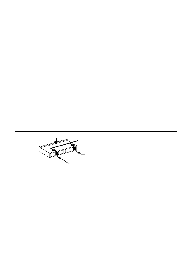
Starter Disable Wiring
Using the wiring information and diagram below, connect the 2-pin white starter disable plug as follows:
A. Cut the ignition switch (Starter Wire).
B. Connect the ignition switch side of the cut "start only" wire to one of the black wire from the 2-pin plug.
C. Connect the remaining "start only" wire to the other black wire from the 2-pin plug.
To test the starter disable system refer to the starter disable testing procedures located in the testing
section of this manual. (Page 16)
2-Pin Plug from
Control Module
"OFF" "ON"
"ACC" "START"
Starter
Cut
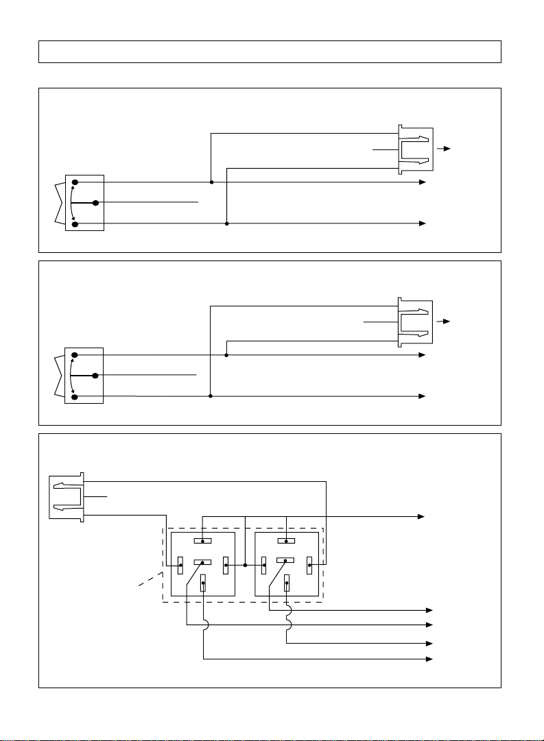
Interrupting Other Circuits
Red Wire
Black Wire
Orange
2-Pin
"ACC" "START"
Interrupt
One Circuit
Use ALA-RPS
Black Wire
"OFF" "ON"
IInterrupt Two Circuits
Use ALA-RPS2
87
87a
86
85
30
Black Wire
CUT
White Wire
86
CUT
87
87a
85
30
White Wire
Power Supply
to Fuel Pump
or
Power Supply to
Fuel Injectors
Power Supply
to ECM
or
Power Supply to
Ignition Coil
9
Page 10

Step 5: Optional Accessory Connections (Continued)
Flashing Parking Lights
Headlight Switch
Piggyback
Red Wire with White Stripe
Output from Alarm
Alarm Status LED and LED/Valet Switch Holder
LED Harness
2-Pin (White)
Valet Switch
2-Pin (Blue)
Dual Zone Electronic Sensor Plug: (Applies to PLUS-4000 Only)
Red Wire: +12 Volt Sensor Power Supply
Black Wire: Sensor Ground Supply
Blue Wire: Sensor Alarm Trigger Output
Green Wire: Sensor Pre-Warning Output
Connection
LED/Valet
Switch Holder
Parking
Lights
Only
Plug-In
LED
4 Pin White Plug
Optional Dome Light Illumination and Lighted Pathway Illumination
Black Wire
Red Wire
White/Purple Wire
Headlight Switch
Warning! Piggyback connections to Lowbeam Headlights
or Parking Lights
10
(one or the other but not both)
ALA-RPT2
Relay Pack
White/Orange Wire
Input to Relay (+ or - )
Purple Wire
Orange Wire
Output to Domelight
(+ or - )
Input to Relay
(+ or - )
Low Beam
Headlights
or
Parking Lights
Page 11

Step 5: Optional Accessory Connections (Continued)
Dome Light Supervision Using Optional ALA-RPT Relay Pack:
Insert Black Wire into the First Socket
Insert Red Wire into the Second Socket
Black Wire
Red Wire
ALA-RPT
Relay Pack
Dome Light Supervision Using Optional 30 Amp Relay:
Orange Wire
Output to Dome Light (+ or -)
Purple Wire
Input to Relay (+ or
-
)
Insert Orange Wire into
the First Socket
Orange Wire
(SPST ALA984H
Relay Not Supplied)
87
86
30
Output to Dome Light (+ or -)
To Constant +12 Volts
85
Input to Relay (+ or
#2 Button Power Trunk Activation Using Optional ALA-RPT Relay Pack
Insert Red Wire into the First Socket
Insert Black Wire into the Eighth Socket
Red Wire
Black Wire
ALA-RPT
Relay Pack
Orange Wire
Output to Trunk Switch
Purple Wire
Input to Relay (+ or
#2 Button Power Trunk Activation Using Optional 30 Amp Relay
Insert White Wire with Black Stripe
into the Eighth Socket
White Wire with
Black Stripe
(SPST ALA984H
Relay Not Supplied)
87
86
30
Output to Power Trunk Switch
To Constant +12 Volts
85
Input to Relay (+ or
-
)
-
)
-
)
11
Page 12

Step 6: Transmitter Programming
Step 1 Step 2
Note shape of housing.
Insert the Valet Switch
and Make Sure the
Valet/Override Switch is
in the “Off” Position
Step 3
ON
Turn On Ignition
"Off"
Positon
"On"
Positon
Step 4
2x
Push the Valet Switch 2
Times
(Represent 1 Time On/Off)
The siren/horn will stop sounding, the
parking lights will stop flashing and
the LED will be solid red.
Plug In the Power
Harness
The siren/horn will start sounding, the
parking lights will flash and the LED
will begin flashing
Step 5
4x
Push the Valet Switch 4
Times
(Represent 2 Times On/Off)
The siren/horn will chirp 1 time. You
are now in the transmitter code
programming mode.
12
Page 13

☛
☛
Step 6: Transmitter Programming (Continued)
☛
☛
☛
☛
☛
Step 6
Arm/Dis #2
Regular
The LED will begin flashing slowly and the horn/siren will emit 1 short chirp. The code has now been learned.
Note 1: “Regular” transmitters supplied are “Not” coded alike so you need to code in the second transmitter now by pushing the “Arm/Dis”
button on the second transmitter. Go to Step 7.
Note 2: “Code Hopping” transmitters supplied are “Not” coded alike so you need to code in the second transmitter now by pushing the
“Lock” button on the second transmitter.
Note 3: If you are coding a “Code Hopping” transmitters, skip steps 7, 8, 9 and 10 and go to step 11. No further coding procedures are
necessary. Code hopping transmitters learn all button functions when the “
Step 7
Regular
Arm/Dis
R
Push Arm/ Disarm (Regular) or Lock Button (Code Hopping)
#2
Regular
Arm/Dis #2
Regular
Lock
” button is learned.
Arm/Dis #2
R
Step 8
Code
Hopping
#3
LOCK
PANIC AUX
UNLOCK
2x
To Code #2 Button Push
the Valet Switch 2 Times
(Represent 1 Time On/Off)
The LED will be solid red and the
horn/siren will chirp 1 time.
To Code #3 Button Push
the Valet Switch 2 Times
(Represent 1 Time On/Off)
The LED will be solid red and the
horn/siren will chirp 1 time.
Step 9
R
The LED will begin flashing slowly and the horn/siren will chirp 2 times.
Note 1:
“Regular” transmitters supplied are “Not” coded alike so you need to code in the
second transmitter now by pushing the #2 button on the second transmitter.
Step 10
2x
Push the “#3” Button
The LED will begin flashing slowly and the
horn/siren will chirp 3 times.
Note 1:
“Regular” transmitters supplied are “Not” coded
alike so you need to code in the second transmitter now
by pushing the #3 button on the second transmitter.
☛
Push the “#2” Button
☛
R
Step 11
OFF
Turn Off the Ignition
The horn/siren will emit 1
short chirp and 1 long chirp.
You are now out of the
consumer transmitter code
learning mode. The LED is off.
☛
13
Page 14

Step 7: Remote Feature Programming
When the Carbine security system control module learns the transmitter operating code, a specific group
of operating features are automatically programmed to a default setting. These default settings can be
changed by following the enclosed procedure and using the consumer transmitter for programming.
# Programmable Alarm Feature Default Setting
1 Chirp Status Indicator On
2 Last Door Closed Automatic Arming Automatic Arming of Alarm “Off”
3 Ignition Key Controlled Door Lock/ Unlock Off
#3 Button (Channel 3 or Panic Operation)
4A
(3-Button Regular Transmitter Only)
Panic Button (Panic or Channel 3 Operation)
4B
(4-Button Code Hopping Transmitter Only)
Channel #3
Panic
Insert the Valet Switch
and Make Sure the
Valet/Override Switch is
in the “Off” Position
Step 3
Turn On the Ignition
The LED will remain off.
Step 1
Note shape of housing.
ON
"Off"
Positon
Step 2
R
☛
"On"
Positon
Push the Valet Switch 12 Times
The LED will be on solid and the horn/siren will emit
1 long then 1 short chirp. You are now in the
“Remote Feature Programming” mode.
Disarm the Security
System
The LED will be off and the horn/siren
will emit 2 chirps
Step 4
12x
(Represent 6 Times On/Off)
14
Page 15

Step 7: Remote Feature Programming
(Continued)
Step 5
Arm/Dis #2
Regular
# Transmitter Button Function Confirmation = Change Function
Regular
Arm/Dis
R
#2
Regular
Arm/Dis #2
1 ARM/DIS or LOCK Chirp Status Indication 1 Beep = Chirp Status Indication “On”
2 Beeps = Chirp Status Indication “Off”
2 #2 or UNLOCK Last Door Closed
Automatic Arming door is closed and rearm 10 seconds after remote disarm.
1 Beep = Automatic Arming “On”, Alarm will arm 10 seconds after
2 Beeps = Automatic Arming “On”, Alarm will arm 20 seconds after
door is closed and rearm 20 seconds after remote disarm.
3 Beeps = Automatic Arming “On”, Alarm will arm 30 seconds after
door is closed and rearm 60 seconds after remote disarm.
4 Beeps = Automatic Arming “Off”
3 ARM/DIS + #2 Ignition Key Controlled 1 Beep = Door will Lock 3 seconds after Ignition is Turned “On”.
or Door Locks Door will not Unlock when Ignition is Turned “Off”.
LOCK + UNLOCK 2 Beeps = Door will Lock 3 seconds after Ignition is Turned “On”
Door will Unlock when Ignition is Turned “Off”.
3 Beeps = Door will not Lock 3 seconds after Ignition is Turned “On”.
Door will not Unlock when Ignition is Turned “Off” *.
4A #3 Channel 3 Operation or 3 Beeps = Button #3 Operates as a Dedicated Panic Button
3-Button Regular Panic Operation from
Transmitter Only # 3 Transmitter Button
4 Beeps = Button #3 Operates Channel 3 Output of Alarm
4B Panic Panic Operation or 3 Beeps = Panic Button Operates Channel #3 Output of Alarm
4-Button Channel #3 Operation
Code Hopping from Panic Transmitter
Transmitter Only Button
Indicates Default Settings
*
4 Beeps = Panic Button Operates as a Dedicated Panic Button
Regular
Arm/Dis #2
R
Code
Hopping
#3
LOCK
PANIC AUX
UNLOCK
*
*
*
*
OFF
Step 6
Turn Off the Ignition
The horn/siren will emit 1 short chirp
and 1 long chirp. You are now out of
the “Remote Feature Programming”
mode. The LED is off.
15
Page 16

Step 8: Multiple Car Programming
About Multiple Car Programming:
Note 1: Regular Carbine transmitters with 2 buttons can operate 2 Carbine alarm systems. (Alarm
models do not have to be the same)
Note 2: Regular Carbine transmitters with 3 buttons can operate 3 Carbine alarm systems. (Alarm
models do not have to be the same)
Note 3: Code Hopping Carbine transmitters will only operate 1 Carbine alarm system.
To perform multi-car programming, all transmitters must first be marked car to indicate which car/alarm
they are for. ie car #1, car #2 etc. Once this is done, follow the specific programming procedure for each
model alarm you are programming and program the arm/disarm button, Channel #2, and Channel #3
buttons according which car they will operate.
Step 9: General Testing
To test the basic functions of the alarm system (all models) repeat the following procedures.
1. Turn off the ignition key and exit the vehicle closing all protected entrances.
2. Press the arm/disarm or lock button on the transmitter. You will hear a siren/horn chirp, the parking
lights will flash one time and the LED status indicator will flash at normal speed.
3. Wait 5 seconds, then open a protected entrance. The siren/horn will begin to sound. Press the arm/disarm
or unlock button once again and the siren/horn will stop sounding. (No Disarm Chirp Indicator)
Note: If you disarm the alarm when the siren/horn is sounding, there are no disarming chirps. When you
disarm the alarm when the siren is off, there will be disarming chirps.
4. Follow procedures 2 and 3 for all other protected entrances.
Step 10: Speciality Feature and Optional Equipment Testing
Each specialty feature listed operates in the same manner regardless of the alarm model. Test each feature
by following the procedures enclosed to insure proper operation.
Remote Panic:
1. Press and hold the arm/disarm (for regular transmitters) or panic button (for code hopping
transmitters) down for approximately 3 seconds.
2. The alarm will begin to sound and the parking lights will begin to flash.
3. Press the arm/disarm or panic button once again and the siren/horn will stop sounding and the lights
will stop flashing.
Note 1: The remote panic feature has an automatic shut off circuit. When the siren/horn has sounded for
60 seconds, the panic circuit will turn itself off automatically.
Note 2: The remote panic feature can be programmed to operate exclusively from #3 button on a 3button transmitter. (See Remote Feature Programming).
Note 3: The panic button on a 4-button code hopping transmitter can be programmed to operate as the
channel 3 button and not a panic button. (See Remote Feature Programming) Pressing and holding down
the lock button on a 4-button transmitter will always activate the panic feature.
Starter Disable: (Also Applies if ALA-RPS2 was Installed to Interrupt Other Circuits)
1. Enter the vehicle and close all the entrances.
2. Arm the alarm using the transmitter.
3. Turn the ignition key to the start position. The engine will not crank over.
4. Turn the ignition key to the off position and disarm the alarm.
5. Turn the ignition key back to the start position and the engine will crank over and start.
16
Page 17

Step 10: Speciality Feature and Optional Equipment Testing
Override Operation: (Security System is Armed)
1. Enter the vehicle and the security systems will begin sounding at this point. Insert the valet switch into
the holder and make sure that the valet/override switch is in the “off” position
2. Place the ignition key into the ignition switch and turn the ignition switch to the “on” position.
3. Within 5 seconds of turning the ignition key “on”, place the valet switch to the “on” position.
4. The horn/siren will stop sounding.
5. The LED indicator will be solid red.
The security system is overridden and is now in the valet mode!
Note 1: If the valet switch is already in the “on” position when you turn “on” the ignition key, the override
function will be bypassed. Turn “off” the ignition key, place the valet switch in the “off” position and try again.
Note 2: If you fail to place the valet switch to the “on” position within 5 seconds of turning “on” the
ignition key, the override function will be locked out. Place the valet switch in the “off” position, turn “off”
the ignition key and try again.
Valet Operation: (The security system is already disarmed)
1. Insert the valet switch into the holder and make sure that the valet switch is in the “off” position.
2. Turn the ignition key to the “on” position
3. Place the valet switch to the “on” position.
4a. The LED will be on solid indicating that the security system is in the valet mode. (Ignition is on).
4b. The LED will flash one every 5 seconds to indicate valet mode when the ignition is off.
How to Get Back to Security System Activation Mode:
1. Place the ignition key switch to the “on” position.
2. Place the valet switch to the “off” position.
3. Place the ignition key switch back to the “off” position. You will notice that the LED indicator will be
off. This indicates that you have exited the valet mode and your security system will operate normally.
4. Remove the valet switch.
Last Door Automatic Arming: (If Programmed On)
Note: The automatic arming feature will not operate unless the alarm input triggers have been connected
directly to the existing or newly installed door jamb pins. Current sensing alone will not activate the
automatic arming circuit.
1. Disarm the alarm.
2. Set the ignition key to the on position, then turn it off.
3. Exit the vehicle. The siren/horn will chirp 1 time when the door is closed.
4. The LED will begin to flash fast.
5. After 10, 20 or 30 seconds have passed (depending on remote feature programming), you will hear a
single chirp. The alarm is now armed.
6. The LED will flash at a regular rate indicating an armed condition.
Note: When the automatic arming feature is activated, so is the RF tamper re-arm circuit. Every time the
alarm is disarmed by remote, the RF tamper re-arm circuit will count for sixty seconds (LED will be
flashing fast) and the alarm will re-arm itself if no one has entered the vehicle.
17
Page 18

Step 10: Speciality Feature and Optional Equipment Testing
LED Status Indicator Operation:
LED is off = Alarm is disarmed.
LED is flashing = Alarm is armed.
LED is flashing in a 2 flash hold sequence = Tamper warning, alarm was triggered by the hood/
LED flashing in a 3 flash hold sequence = Tamper warning, alarm was triggered by an open door.
LED is on steady = Alarm is in the valet mode. (Ignition key is “on”)
LED flashes once every 5 seconds = Alarm is in the valet mode. (Ignition key is “off”)
LED is flashing fast = Automatic arming timer is counting down or RF tamper rearming timer is counting
down.
Parking Light Flash Alarm Status Indication:
One light flash = Alarm is armed.
Two light flash = Alarm is disarmed.
Three light flash = Tamper indicator, alarm is disarmed.
Siren/Horn Chirp Alarm Status Indication:
Note: This feature can be programmed off, see “Remote Feature Programming” for details.
One chirp = Alarm is armed and all input trigger wires are clear.
Two chirps = Alarm is disarmed and has not been tampered with.
Chirps once, pauses then chirps again = Alarm is armed but sensor is by-passed.
Four chirps = Tamper indicator, alarm is disarmed.
Power Door Lock/Unlock: (If Installed)
1. Arm the alarm with the transmitter, the locks will become locked.
2. Disarm the alarm with the transmitter, the locks will become unlocked.
trunk or electronic sensor.
RF Tamper Re-Arm:
Note: This feature is activated automatically when the alarm is programmed for automatic arming. See
“Remote Feature Programming” for details. (Page 14-15)
1. Alarm must be programmed for automatic arming.
2. Close all protected entrances and arm the alarm with the remote transmitter. The LED will be flashing
at a normal rate.
3. Wait 5 seconds and disarm the alarm using the remote transmitter. The LED will begin to flash fast.
(Automatic arming indicator)
4. Wait 60 seconds and the alarm will become rearmed.
5. Repeat steps 1 through 4. When the LED starts flashing fast, open one of the protected entrances
(door) the LED will be off and remain off.
60 Second Re-Arm Timer and Re-Lock Function:
Once the alarm is triggered, the siren will sound for 60 seconds and then stop. The alarm will remain in
an armed condition. If the door locks have been installed into the system, they will re-lock when the
alarm resets after 60 seconds.
18
Page 19

Step 10: Speciality Feature and Optional Equipment Testing
Ignition Controlled Door Locking: (Door lock activation must be installed)
When programmed on in “Remote Feature Programming”, ignition controlled locking is active 3 seconds
after the ignition key is set the on position, the door locks will automatically become locked. When the
ignition key is turned to the off position, the door locks will unlock.
Note: If a protected entrance (Door) is open when the ignition key is set to the on position, the door locks
will not lock. This is a non-deletable protective measure.
Channel #2 Output: (If Installed)
Press and hold the channel #2 activation button for 3 seconds. The designated channel 2 output wire
from the alarm will become grounded for as long as button #2 is pressed.
Channel #3 Output: (If Installed)
Press and hold the channel #3 activation button for approximately 3 seconds. After 3 seconds the alarm
will emit a ground signal from the channel #3 wire to operate the device connected to the channel #3
output wire of the alarm for as long as channel #3 button is pressed.
Dual Zone Sensor Pre-Warning Indicator: (If Installed)
1. Close all protected entrances and place the alarm in an armed condition.
2. Rap the vehicles body panels to activate the pre-warning zone of any dual zone type sensor.
3. When the pre-warning indicator is triggered, the horn/siren will beep 1 time.
Specifications
Power Requirements ........................ 12.5 Volts Negative Ground
Trigger Inputs .............................. Grounded Pin Switch, Positive Pin Switch,
Current Requirements ....................... Less Than 15mA Armed or Disarmed
Timers .................................... Programmable Automatic Arming Timer
Grounded Output Wire Capacity (White Wire) . . 500mA
Siren Output Wire Capacity .................. 2 amps
Channel 2 Pulsed Output.................... 300mA
By-Pass Zones ............................. 2 Zones
Transmitter Frequency ...................... 302mHz
Digital Code Combinations .................. 500,000 Available
Code Method .............................. Digital Trinary
Transmitter Channels ....................... 2 Channels
Receiver Channels ......................... No More Than 3
Electronic Sensor Ground, 0.6 Volt Current Drop
Programmable Re-Arming Timer
60 Second RF Tamper Re-Arming Timer
5 Second Zone By-Pass Re-Activation Timer
19
Page 20

Wiring Diagram PLUS-5000
Auxilliary Interrupt
Socket (Orange)
(See Optional Accessory Connection)
Black Wire Antenna (Do Not Ground)
Back View of Housing
Auxilliary Interrupt
Socket (Orange)
Dip Switches
ON
4
123
Dip
Switches
Shock Sensor
Socket (White)
Starter Disable
Domelight Supervision
(See Optional Accessory
Connection)
Plug-In LED
(White)
Valet/Override Socket
(Blue)
Power Door Lock Harness Socket
(Black)
Power
Harness
PLUS-5000
Controller
Main
Harness
Channel #2 Output Pulsed Ground
(See Optional Accessory Connection)
Gray Wire Pulsed Ground for
Car Horn
Blue/White Wire
Channel #3 Output (Ground)
Brown Wire Siren Output (+)
Blue Wire Negative AUX Trigger Input
Green Wire Negative Door Pin Trigger Input
Violet Wire Positive Door Pin Trigger Input
Red/White Wire Parking Lights Relay Output
Pink Wire Parking Lights Relay Input
Black Wire Ground to Vehicle Frame
Yellow Wire To Ignition Switched +12V
Red Wire To Battery +12V
(Ground)
11-18-99 rev. B
PLUS50IM
 Loading...