

Carbine PLUS-4500 User & Installation Manual

Models: PLUS-4500
© Copyright 2000 Magnadyne Corporation
INSTALLATION
MANUAL
R
Vehicle Security
For Technical Assistance (800) 638-3600
For Fax on Demand Technical Assistance (800) 994-9977
(Must be a Registered Dealer to Use Fax on Demand System)

Index
Step 1: Component Installation . . . . . . . . . . . . . . . . . . . . . . . . . . . . . . . . . . . . . . . . . . . . . . . . 2-3
Step 2: 10-Pin Main Harness Installation
. . . . . . . . . . . . . . . . . . . . . . . . . . . . . . . . . . . . . . . . . 3-4
Step 3: 5-Pin Power Harness Installation
. . . . . . . . . . . . . . . . . . . . . . . . . . . . . . . . . . . . . . . . 4-5
Step 4: DIP Switch Programming . . . . . . . . . . . . . . . . . . . . . . . . . . . . . . . . . . . . . . . . 5 Step 5
Optional Accessory Connections
. . . . . . . . . . . . . . . . . . . . . . . . . . . . . . . . . . . . . . . 6-11 Step 6
Transmitter Programming
. . . . . . . . . . . . . . . . . . . . . . . . . . . . . . . . . . . . . . . . . . 11-12 Step 7
Remote Feature Programming . . . . . . . . . . . . . . . . . . . . . . . . . . . . . . . . . . . . . . . . 13-14 Step 8
General Testing . . . . . . . . . . . . . . . . . . . . . . . . . . . . . . . . . . . . . . . . . . . . . . . . . . . . 15 Step 9
Speciality Feature and Optional Equipment Testing . . . . . . . . . . . . . . . . . . . . . . . . 15-18
Specifications . . . . . . . . . . . . . . . . . . . . . . . . . . . . . . . . . . . . . . . . . . . . . . . . . . . . . . . . . . . 18
Wiring Diagrams . . . . . . . . . . . . . . . . . . . . . . . . . . . . . . . . . . . . . . . . . . . . . . . . . . . . 19
Step 1: Component Installation
Mounting the Control Module:
Find a suitable location to secure the alarm control module within the passengers compartment of the
vehicle. Never mount the alarm control module in the engine compartment or in the trunk. In addition,
never mount the alarm control module in the direct path of the heater. Secure the alarm control module
by using wire ties or drill two 1/8” holes and secure the module to the frame of the vehicle with the
screws provided.
Mounting the Siren:
Find a suitable location in the engine compartment to secure the siren. Select a location that provides a
direct sound path to the ground for maximum siren output. Use the self tapping screws provided and
secure the siren. Connect the black wire coming from the siren to the frame of the vehicle. In many
cases, you can ground the black wire to one of the screws used to secure the siren. Run the remaining
brown wire through the fire wall to the location of the alarm control module.
Installing Hood/ Trunk Pin Switches:
Provided with the alarm kit is one pin switch and one mounting bracket. To install the switch either in the
truck or under the hood, find a suitable location where the switch will make contact with the hood or
trunk lid and will not get wet. Use the bracket provided or drill a 1/4” hole in the desired location.
2
Warning! Do not plug the 10-pin or 5-pin wire harness into the alarm control module before you begin
installing the alarm. The wire harnesses must be plugged into the alarm control module after all
connections are made. Failure to follow this procedure could cause some confusion with transmitter
operation and or alarm function operation.
The PLUS-4500 security system are packaged 2 different ways for maximum flexibility. Even though the
systems are packaged 2 different ways they all contain the same module and installation harnesses. The
following is how each model number is packaged:
PLUS-4500: 4500 Alarm Module with no transmitters and no siren.
PLUS-4500C: 4500 Alarm Module with (2) 4-button code-hopping transmitters and a siren.
Step 2: 10-Pin Main Harness Installation
The main wire harness contains 8 wires which all have a specific purpose. Follow the wiring
recommendations enclosed for each wire. Wires not used should be released from the harness connector
or taped off to prevent accidental shorting. Included with the 10-pin wire harness are two loose wires, an
orange wire and a white wire with black stripe. See main harness and power harness wiring instructions
for these two loose wires. (Page 4)
3
Step 1: Component Installation (Continued)
Mounting the Override /Valet Switch:
Mount this switch in a hidden but accessible location within reach of the driver of the vehicle. Drill a 1/4”
hole and use the nuts and washers provided to secure the switch. Run the wires from the switch to the
alarm control housing location.
Installing the Alarm Status LED:
The LED indicator provided utilizes a push in type mounting. Drill a 5/16” hole in the desired location,
feed the wires through the hole and push the LED into place. Run the wires to the location of the alarm
control module.
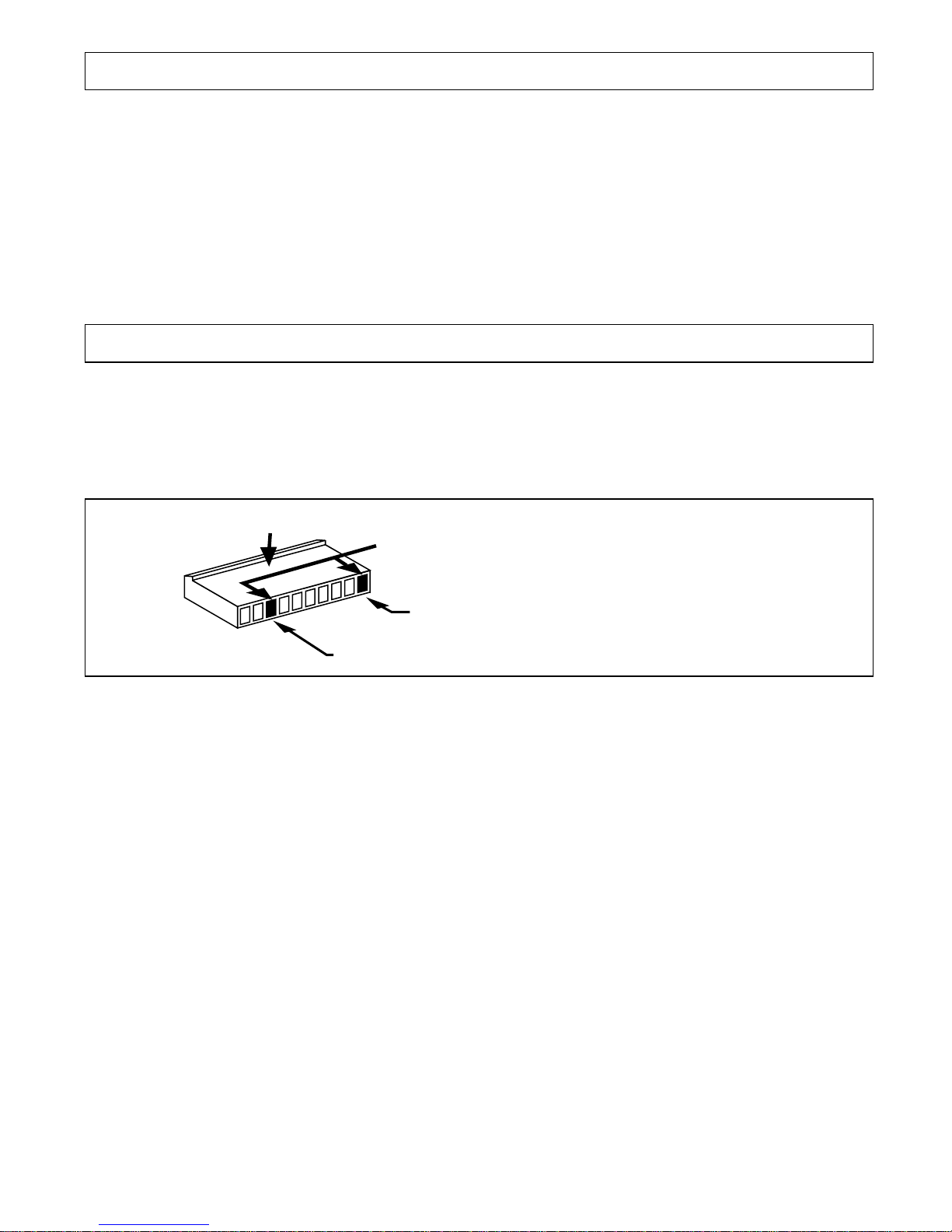
Vacant Sockets
Main Harness
First Vacant Socket (Located in the 1st Position)
Second Vacant Socket (Located in the 8th Position)
First Vacant Socket: (For Use with ALA-RPT Relay Pack Only)
See Optional Accessory Connection for proper wiring. (Page 10)
Gray Wire: (No Connection)
Blue Wire with White Stripe: (No Connection)
Brown Wire: (Siren + Output)
Connect the brown wire to the positive wire from the siren. Ground the remaining wire from the siren for
proper operation.
Blue Wire: (Optional Grounding Sensor Input)
The blue wire is an instant grounding trigger input for optional hood/trunk grounded pin switches or any
electronic sensor.
Step 3: 5-Pin Power Harness Installation
The power harness contains 3 wires and two vacant sockets. Follow the wiring recommendations enclosed
for each wire.
4
Step 2: 10-Pin Main Harness Installation (Continued)
Green Wire: (Grounded Door Pin Switch Input)
The green wire connects to the common wire of the vehicle that switches on the dome light. Normally
this wire is located at one of the door jamb switches. For some vehicles it may be necessary to connect
the green wire directly to the switched turn on wire at the dome light. The green wire connects to
negative switched circuits only.
Violet Wire: (Positive Door Pin Switch Input)
The violet wire connects to the common wire of the vehicle that switches on the dome light. Normally
this wire is located at one of the door jamb switches. For some vehicles it may be necessary to connect
the violet wire directly to the switched turn on wire at the dome light. The violet wire connects to positive
switched circuits only.
Second Vacant Socket:
The second vacant wire socket provides a 1 second pulsed ground (300mA) output when channel #2 is
activated. (See Optional Accessory Connections) (Page 10)
Red / White: (Pulsed Parking Light Relay Output)
Connect the red/white wire to the parking light wire coming from the headlight switch. (Do not connect
the red/white wire to the dashboard lighting dimmer switch. Damage to the dimmer will result) use a volt
meter to test the connection point before connecting the red/white wire. While checking, rotate the
dimmer switch to make sure you do not have the dimmer lead. The limitation of the red/white wire is 10
Amp max. Do not exceed this limit or damage to the alarm and parking light relay will result.
Pink: (Parking Light Relay Input)
The pink wire is the input to the flashing parking light relay. The connection of the pink wire will determine
the output polarity of the flashing parking light relay. Connect the pink wire to (+) battery to have (+)
output from the relay or connect the pink wire to frame ground to have ground output from the
relay.
First Vacant Socket:
The first vacant wire socket is a low current (300mA) grounded output wire that can be used to activate
the vehicle’s interior lighting system when the security system is disarmed. An additional relay is
required for proper installation. See Optional Accessory Connection for proper wiring. (Page 10)
Second Vacant Socket: (For Use with ALA-RPT Relay Pack Only)
See Optional Accessory Connection for proper wiring. (Page 10)
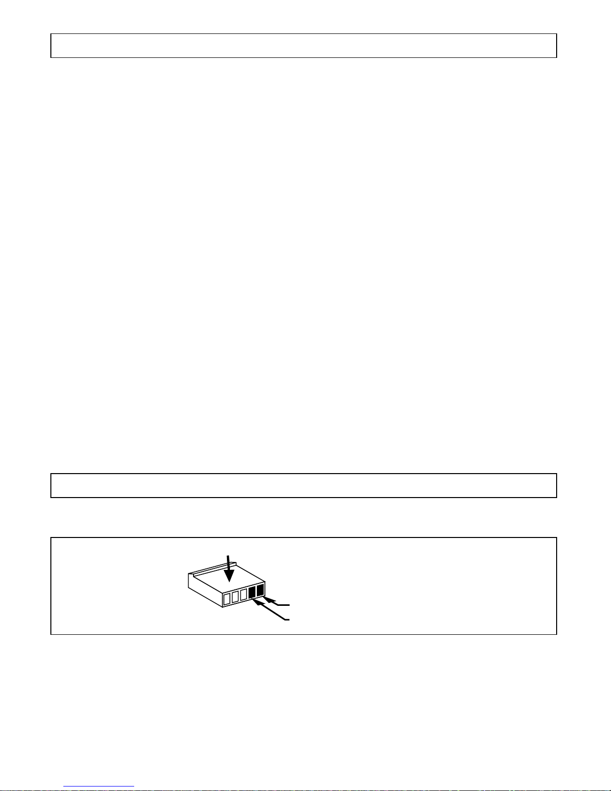
Power Harness
First Socket
Second Socket
Switch #1: Power Door Lock Output Timing
Set switch #1 to the on position for a .8 second duration output (Common setting for all Japanese
and American vehicles)
Set switch #1 to the off position for a 3.5 second duration output (European vacuum locking system
only)
Switch #2: Passive Arm Locking Control
Set switch #2 to the on position to allow the door locks to lock when the alarm automatically arms.
Set switch #2 to the off position to prevent the door locks from locking when the alarm automatically
arms.
Switch #3: Current Sensing ON/OFF
Set switch #3 to the on position to activate the current sensing trigger circuit.
Set switch #3 to the off position to eliminate the current sensing trigger circuit.
Step 4: DIP Switch Programming
5
Step 3: 5-Pin Power Harness Installation (Continued)
Red Wire: (Main Power Input)
Connect the red wire directly to the (+) battery post for best operation of the alarm system. For best
current sensing capability from the alarm’s current sensing circuit, connect the red wire to the constant
power wire coming from the interior dome light.
Black Wire: (Main Ground Input)
Connect the black wire directly to the frame of the vehicle. Use a bolt and nut to secure the wire. Scrape
away any grease or paint that might prevent a good connection.
Yellow Wire: (Switched +12 Volts From the Ignition Switch)
Connect the yellow wire to a +12 volt wire that is switched on and off by the ignition key. The correct wire
will indicate +12 volts when the ignition key is in the on and start positions. Do not connect the yellow
wire to the “acc” wire coming from the ignition switch.
Power Door Lock/Unlock Activation
Step 5: Optional Accessory Connections
6
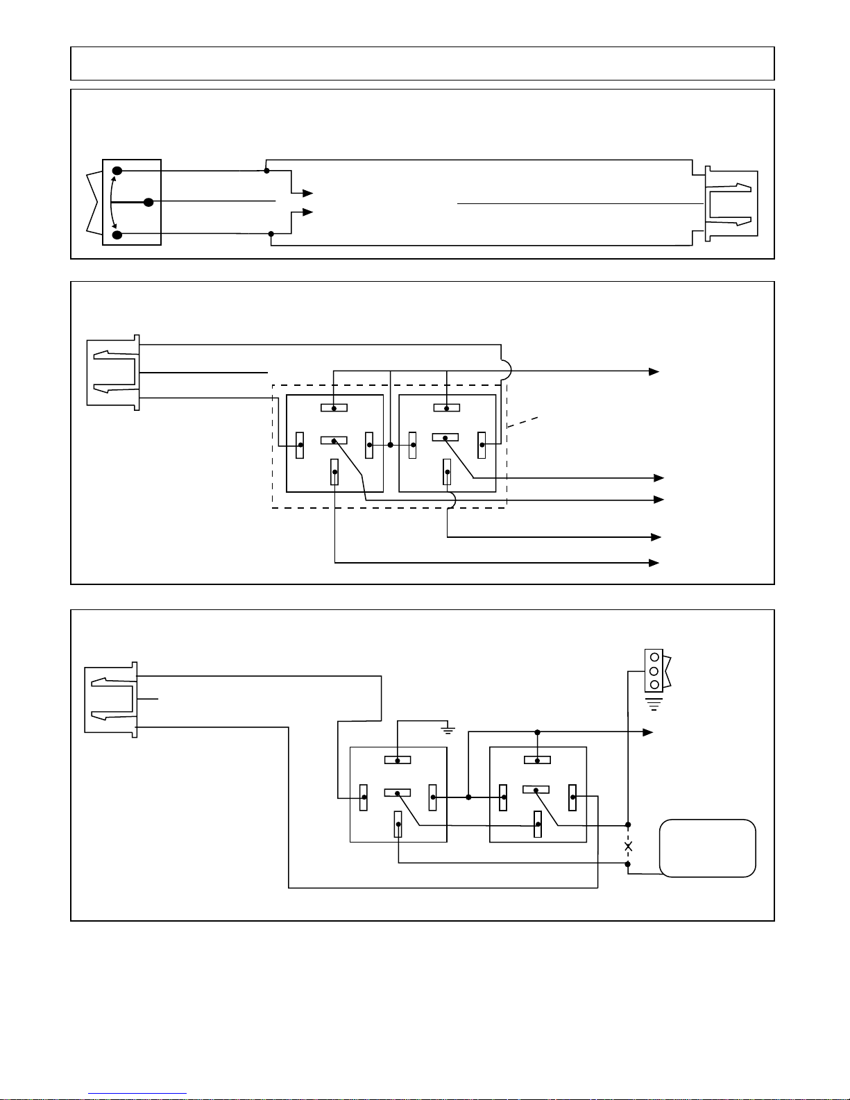
5 Wire Ground at Rest Door Locking Systems
87
87A
85
86
30
87
87A
85
86
30
To +12 Volts
(Battery +)
To Power
Lock Switch
To Power
Lock Motors
White Wire: Lock
Green Wire: Lock
Blue Wire: Unlock
Brown Wire: Unlock
Black Wire Unlock
Red Wire Lock
3 Pin Black Plug
Orange Wire
Note: No Connection
on Orange Wire
Violet Wire:
ALA-DL1
Relay Pack
Mercedes Door Lock Activation
Door Lock
Switch
87
87A
85
86
30
87
87A
85
86
30
To +12 Volts
(Battery +)
Door Lock
Compressor
Cut
Green Wire
Black Wire: Unlock
Lock
Unlock
B+ Unlock
Lock
+
++--
Red Wire: Lock
Orange Wire: No Connection
3 Pin
Black
Plug
Step 5: Optional Accessory Connections
Note: Prewired Door Lock
Interconnect T-Harness are
Available for Most Vehicles
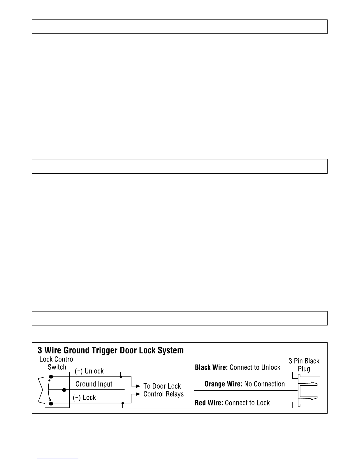
3 Wire Positive Trigger Door Lock System (Applies to PLUS-4000 Only)
(+) Lock Out
+12 Volts Input
(+) Unlock Out
To Door Lock
Control Relays
Black Wire: Connect to Lock
Red Wire: Connect to Unlock
Orange Wire: No Connection
Lock Control
Switch
3 Pin Black
Plug
 Loading...