

Carbine CFB-HB Instructions Manual
The Next Generation in Locking
CFB-HB FLIP BOLT MORTICE LOCK - HOLD BACK MODEL
INSTALLATION INTO METAL HOLLOW STYLE DOORS
CFB-HB - Flip Bolt Mortice Lock - Hold Back Model
Provides the feature of hold back when installed with
1
2
CFB-CSL - Flip Bolt Mortice Lock - Concealed Short Lever.
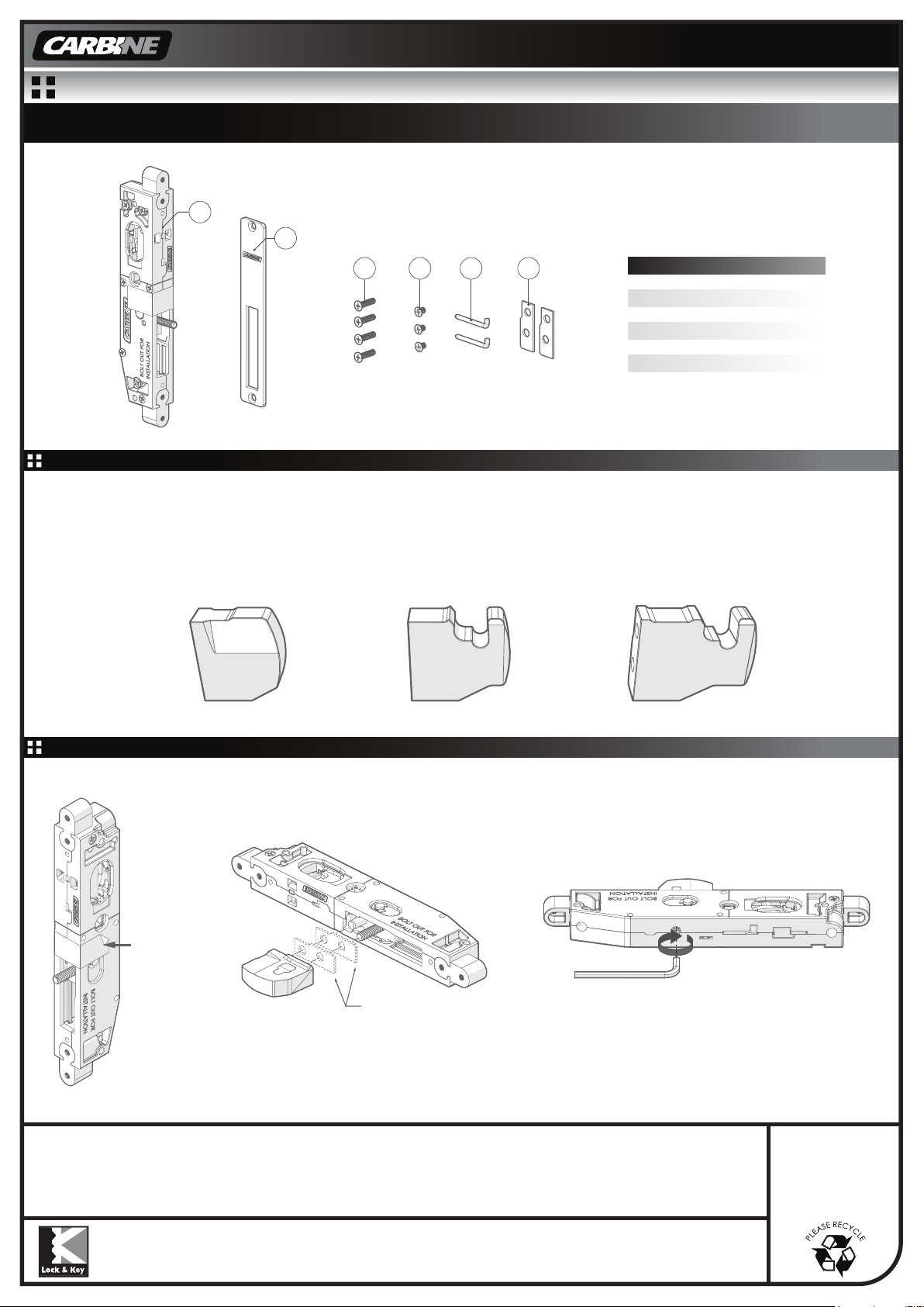
1. MORTICE LOCK BOLT SELECTION - Bolts are sold separately
Select bolt appropriate for application.
CFB-141A - Taper Bolt SS
Hinged Metal Hollow Style Door
Hinged Timber Door
(22mm bolt projection when installed)
3 4 5 6
CFB-142A - Hook Bolt Short SS
Sliding Metal Hollow Style Door
Sliding Timber Door
(28mm bolt projection when installed)
Item No. Desc ription QTY
1 Main Lock 1
2 Cover Plate 1
M4 x 16 CSK Screw 4
3
M4 x 6 CSK Screw 3
4
5
6
Retainer Pin 2
Bolt Packer 2
CFB-143A - Hook Bolt Long SS
Sliding Metal Hollow Style Door
Sliding Timber Door
(35mm bolt projection when installed)
2. ASSEMBLY OF FLIP BOLT INTO MORTICE LOCK
2B Insert chosen flip bolt
(sold separately) into lock.
*If necessary, insert bolt packers
into lock prior to flip bolt.
Bolt Packers (if required)
Only for CFB-141A - Taper Bolt SS
2A Remove transport tape
CFB-142A - Hook Bolt Short SS
off the lock.
Special Notes:
For installation together with CLS-FAB - Flip Bolt Latching Strike, please refer to installation instructions provided with CLS-FAB.
For installation together with CFB-OES - Oval Escape Turn, please refer to installation instructions provided with CFB-OES.
For installation together with CFB-OTS - Oval Turn Snib, please refer to installation instructions provided with CFB-OTS.
For installation together with CFB-OCEP - Oval Cylinder Rectangular Escutcheon, please refer to installation instructions provided with CFB-OCEP.
LOCK & KEY Phone: 1300 652 692 Web: www.locknkey.com.au Web: www. daveweb.com.au
Distributed in Australia by
LOCK AND KEY a division on the
DAVCOR GROUP PTY LTD ABN 95 003 562 598
This product has been manufactured in Taiwan
to Lock and Key Company specifications
This product is guaranteed to be free from defects in materials and
workmanship for a period of one (1) year from the date of original
purchase. This warranty is for replacement of product only and Lock
and Key Company does not accept responsibility for any direct or
consequential damage caused by this product or its use. This warranty
does not cover damage
alteration or modification of the product or tarnishing of the finish
including colour change due to weather, salt or chemical. Should this
product not perform satisfactorily in its intended application, return it
to place of purchase for replacement.
2C Securely tighten the round
bolt in the clockwise direction
using a 4mm allen key.
CFB-HB - Installation Instructions Revision 2 - 14th March 2019
that results from faulty installation or usage,
WARNING
Please keep contents
away from small children.
Suffocation Hazard.
NOTE
Please dispose of plastic
bags and other packaging
in a thoughtful manner
The Next Generation in Locking
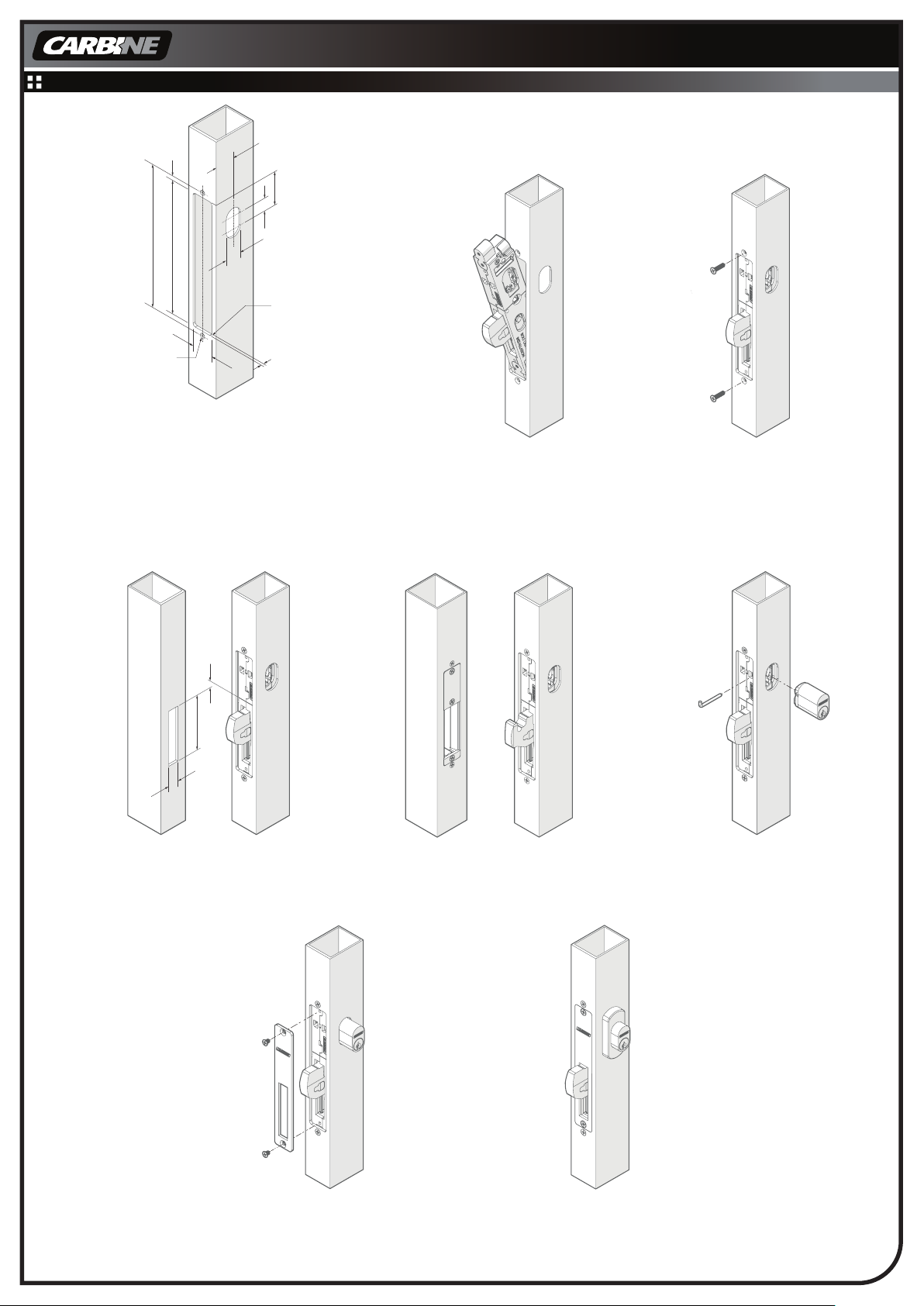
3. INSTALLATION OF THE MORTICE LOCK (METAL HOLLOW STYLE DOOR)
20 + DOOR EDGE
EXTRUSION
THICKNESS
39
14
19
R3
DOOR EDGE
EXTRUSION
THICKNESS
167
156
25.4
Drill 2 x Ø4 holes
and Countersunk
Ø6 x 90°
5.5
3A Prepare door by cutting openings for
fitment of cover plate and oval cylinder.
Please note: if installing together with:
● CFB-CSL - Flip Bolt Mortice Lock - Concealed Short lever
please refer to instructions provided with CFB-CSL.
● CFB-EH - Flip Bolt Mortice Lock - Egress please refer to
instructions provided with CFB-EH.
For hinged door For sliding door
For installation requiring a
saver plate (sold seperately),
please refer to section 4.
3B Insert lock into door cavity.
Ensure bolt is extended.
3C Secure with
2x M4x16mm CSK Screws.
7.5
72
14
3D Measure and cut slot in door jamb.
*If retrofitting, ignore this step.
For sliding doors use
Carbine CLS-FAB flip bolt latching strike,
for installation instructions refer to
instructions supplied with CLS-FAB
3E Insert oval key cylinder and secure
with retainer pin.
Test functionality of lock before fitting
cover plate.
*If required, fit bolt packers.
CFB-HB - Installation Instructions Revision 2 - 14th March 2019
3F Insert cover plate into lock
and secure with
2x M4x6mm CSK Screws.
3G Complete installation with
CFB-OCEP
Carbine Oval Cylinder
Rectangular Escutcheon.
 Loading...