

Page 1

v.LOGiC Intelligent Solution
Interface
V6-MIB
Compatible with various MIB systems
in Audi, Porsche, Skoda and VW vehicles
Version 01.02.2019 V6-MIB
Page 2

Page
1
"
Product features
• Picture-in-picture mode combining after-market rear-view and front camera
picture(s) with factory parking sensor graphics
• Interactive lane lines with calibration function
• Simultaneous use of picture-in-picture factory parking sensor graphics and interactive
lane lines
• Own on-screen display and setup
• Controls of AV sources (e.g. DVB-T Tuner, ...) by MIB system
• Rear-view camera input
• Automatic switching to rear-view camera input on engagement of reverse gear from
all operation modes
• Front camera input
• Side camera inputs
• Side- or front camera activation via blinker signal
• Manual switching to cameras
• 2 trigger outputs (+12V max. 1A), separately adjustable switching events (CAN, ACC,
camera, reverse gear)
• Compatible with all factory video accessories
• USB update-port for software-updates by consumer
Version 01.02.2019 V6-MIB
Page 3

Page
2
"
Contents
1. Prior to Installation
1.1. Delivery contents
1.2. Check compatibility of vehicle and accessories
1.3. Setting the dip switches of the interface-box V6C-M655
1.4. LED’s of the interface-box V6C-M655
2. Connection schema
3. Installation
3.1. Connecting interface-box and harnesses
3.2. LVDS connection
3.2.1. After-market front camera
3.2.1.1. Connection to the after-market front camera
3.2.1.2. Settings for connecting an after-market front camera
3.2.2. After-market wide view front camera
3.2.2.1. Connection to the after-market wide view front camera
3.2.2.2. Settings for connecting an after-market wide view front camera
3.2.3. After-market side view cameras
3.2.3.1. Connection of the after-market side view cameras
3.2.3.2. Settings for connecting of after-market side view cameras
3.2.4. After-market rear-view camera
3.2.4.1. Connection to the after-market rear-view camera
3.2.4.2. Settings for connecting an after-market rear-view camera
3.2.4.3. Settings for OEM rear-view camera
3.2.5. AV source
3.2.5.1. AV source video connection
3.2.5.2. AV source audio connection
3.2.5.3. Settings for connecting an AV source
3.2.6. Configurable trigger outputs
3.3. Interactive lane lines
3.3.1. Interactive lane lines settings
3.4. Picture settings
Version 01.02.2019 V6-MIB
Page 4

Page
3
"
4. Operation
4.1. Main OSD On-screen display
4.1.1. OSD – Operation
4.1.1.1. Audi OSD control
4.1.1.2. VW OSD control
4.1.1.3. Porsche OSD control
4.1.2. OSD – Additional setting options
4.2. Selecting the interface as current video source
4.3. Assigning device controls
4.4. Controlling of the connected AV source
4.4.1. Audi AV source control
4.4.2. VW / Skoda AV source control
4.4.3. Porsche AV source control
5. Specifications
6. Connections (interface-box)
7. Technical support
Legal Information
By law, watching moving pictures while driving is prohibited, the driver must not be
distracted. We do not accept any liability for material damage or personal injury resulting,
directly or indirectly, from installation or operation of this product. This product should only
be used while standing or to display fixed menus or rear-view-camera video when the
vehicle is moving, for example the MP3 menu for DVD upgrades.
Changes/updates of the vehicle’s software can cause malfunctions of the interface. We
offer free software-updates for our interfaces for one year after purchase. To receive a free
update, the interface must be sent in at own cost. Labor cost for and other expenses
involved with the software-updates will not be refunded.
Version 01.02.2019 V6-MIB
Page 5
Page
4
"
Requirements
Brand
Compatible vehicles
Compatible systems
Audi
A3 (8V) from 05/2012-, A4 (8W) from
08/2015-, Q7 (4M) ab 03/2015-
MMI Navigation Plus with
MMI touch 7"or 8.3" MIB/MIB II main-unit
Porsche
Cayenne, Boxster, 911, Cayman
PCM 4.0
Skoda
Octavia 2017-
MIB - Amundsen 8”
VW
Golf7 MY 2015-, Golf7 Sportsvan MJ
2015-, Passat (B8) MY 2015-,
T-Roc MY 2017-
MIB/MIB2 - Discovery Pro 8”
and Composition Media - 6.5”
monitor.
Interface-box
V6C-M655
HW_____ SW_____
Take down the SW-version and HW-version of the interface boxes, and store this
manual for support purposes.
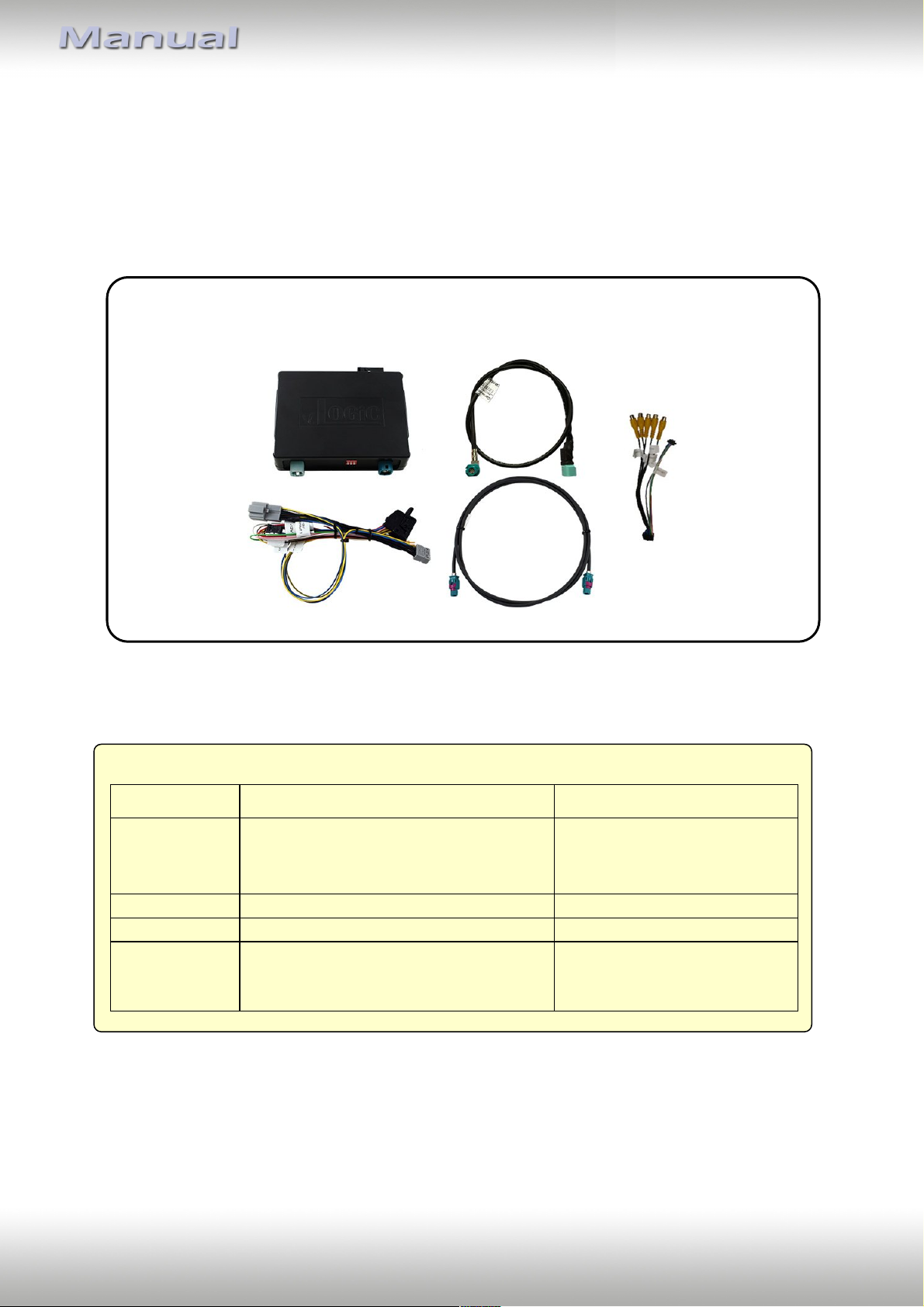
V6C-MIB01
harness
LVDS cable
CAB-HSD-MG060-OZ
LVDS cable
CAB-HSD-FF150
V4C-VIDEO
harness
1. Prior to installation
Read the manual prior to installation. Technical knowledge is necessary for installation. The
place of installation must be free of moisture and away from heat sources.
1.1. Delivery contents
1.2. Check compatibility of vehicle and accessories
Version 01.02.2019 V6-MIB
Page 6
Page
5
"
Vehicle
Monitor
Dip 1
Dip 2
Dip 3
Audi A3 (8V), Audi A4 (8W)
7“
ON
OFF
OFF
Audi A4 (8W)
8,3“
ON
ON
ON
Audi Q7 (4M)
8,3“
ON
OFF
ON
Porsche Cayenne, Boxster, 911, Cayman
7“
ON
ON
OFF
Skoda Octavia 3
8“
OFF
OFF
ON
VW Golf 7, Sportsvan
6,5“
OFF
ON
OFF
VW Passat (B8)
6,5“
OFF
ON
ON
VW Passat (B8), T-Roc
8“
ON
ON
OFF
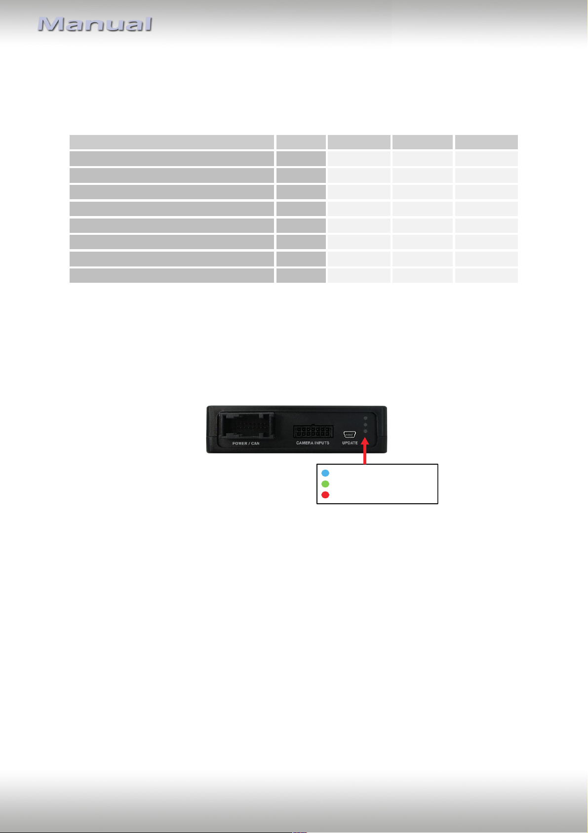
Valid input source
CAN ok
Power
1.3. Setting the dip switches of the interface-box V6C-M655
Dip 1 on the back of the interface-box V6C-M655 are used to set the monitor type. The
default setting is:
After each change of the dip switch settings you have to execute a power reset of the
interface-box!
1.4. LED‘s of the interface-box V6C-M655
Version 01.02.2019 V6-MIB
Page 7
Page
6
"
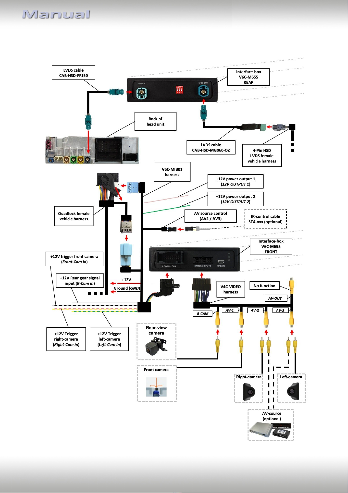
2. Connection scheme
Version 01.02.2019 V6-MIB
Page 8
Page
7
"
Back of
head unit
Interface-box
V6C-M655
FRONT
Quadlock female
vehicle harness
Ground (GND)
+12V
1
2
3
4
5
R-CAM
AV-1 AV-2
AV-3
V4C-VIDEO
harness
V6C-MIB01
harness
6
3. Installation
Switch off ignition and disconnect the vehicle’s battery! The interface needs a permanent
12V source. If according to factory rules disconnecting the battery is to be avoided, it is
usually sufficient to put the vehicle is sleep-mode. In case the sleep-mode does not show
success, disconnect the battery with a resistor lead.
If power source is not taken directly from the battery, the connection has to be checked
for being start-up proven and permanent.
Prior to wire and device installation we suggest to connect and test correct function of all
after-market and factory infotainment equipment!
The interface is installed on the backside of the head unit.
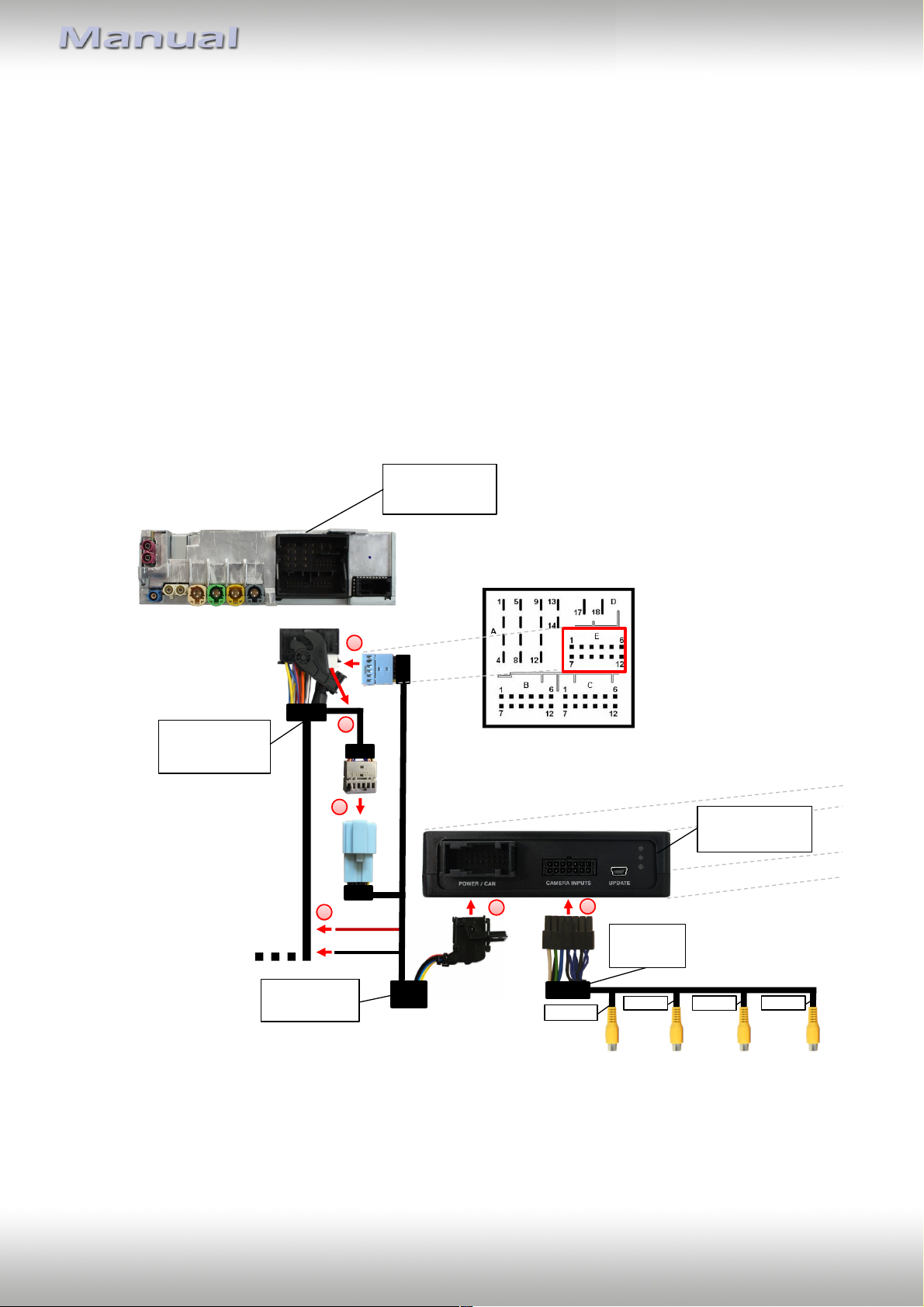
3.1. Connecting interface box and harnesses
Version 01.02.2019 V6-MIB
Page 9
Page
8
"
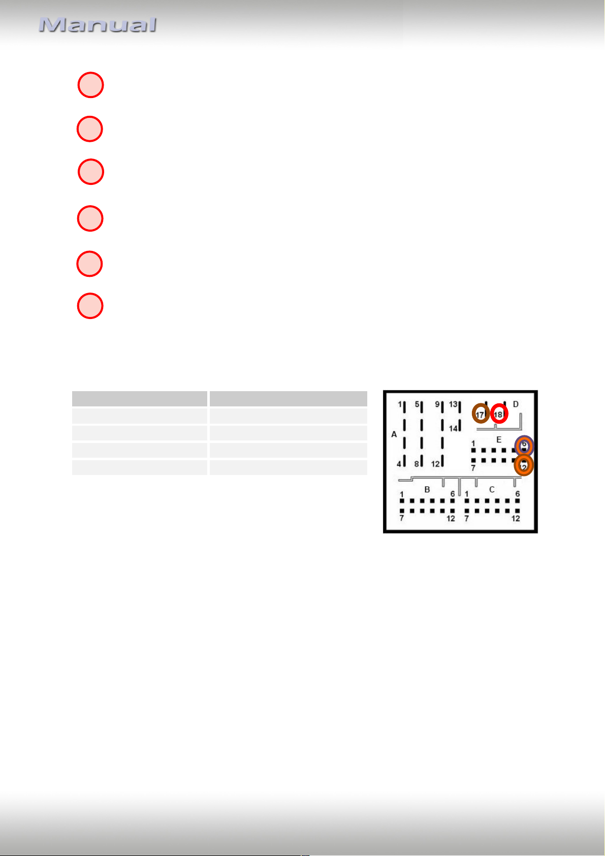
Cable colour
Assignment
● Red
+12V permanent - pin 18
● Brown
Ground - Pin 17
●● Orange/Violett
CAN HIGH - Pin 6
●● Orange/Brown
CAN LOW - Pin 12
Quadlock
1
3
4 5 6
2
Disconnect Quadlock connector from the head unit and remove the 12pin connector
from chamber "E".
Plug in the original vehicle Quadlock 12Pin connector to the 12pin socket of the
V6C-MIB01 harness.
Plug in the 12 pin connector of the V6C-MIB01 harness to chamber "E" of the vehicle
Quadlock connector.
Connect red wire with +12V (Quadlock connector pin 18, chamber D) and black wire
with ground (Quadlock connector pin 17, chamber D).
Plug in the 18 pin AMP connector of the V6C-MIB01 harness to 18pin socket of the
V6C-M655 interface.
Plug in the 14pin connector of the V4C-VIDEO harness to 14pin socket of the
V6C-M655 interface and connect back the vehicle Quadlock to the head unit.
Connection assignment:
Version 01.02.2019 V6-MIB
Page 10
Page
9
"
1
2 3 4
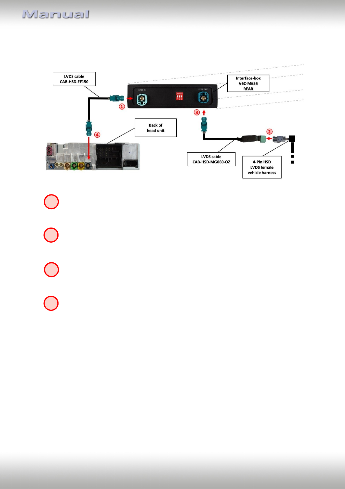
3.2. LVDS connection
Connect the female 4pin HSD LVDS connector of the LVDS cable CAB-HSD-FF150
to the male 4pin HSD LVDS connector (LVDS IN) on the rear of the interface-box
V6C-M655.
Remove the gray / green(Porsche PCM4.0 only) or pink (MIB system specific) female
4pin HSD LVDS connector of the vehicle harness at the back of the head unit and
connect it to the male 4pin HSD LVDS of the CAB-HSD-MG060-OZ LVDS cable.
Connect the female 4pin HSD LVDS connector of the LVDS cable CAB-HSD-MG060-OZ
to the male 4pin HSD LVDS connector (LVDS OUT) on the rear of the interface box
V6C-M655.
Connect the female 4pin HSD LVDS connector of the LVDS cable CAB-HSD-FF150
to the gray/green(Porsche PCM4.0 only)/pink male 4pin HSD LVDS connector on the
rear of the head unit.
Version 01.02.2019 V6-MIB
Page 11
Page
10
"
Interface-box
V6C-M655
FRONT
Front camera
V6C-MIB01
harness
+12V power output 1
(12V OUTPUT 1)
R-CAM
AV-1
AV-2
AV-3
V4C-VIDEO
harness
1
2
1
2
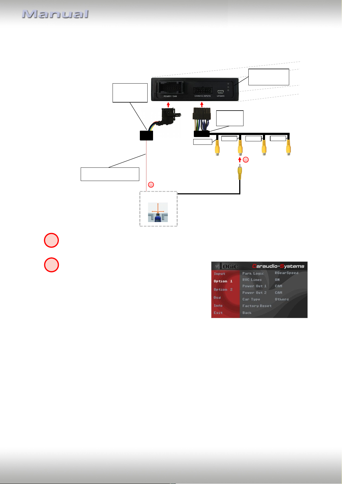
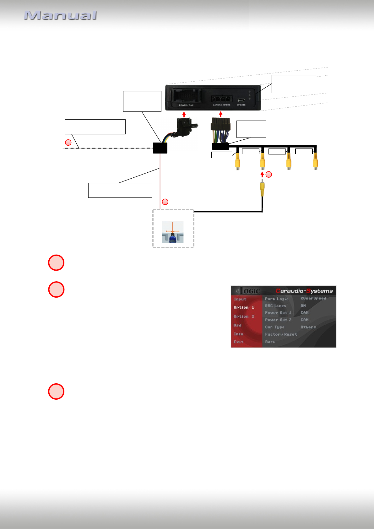
3.2.1. After-market front camera
3.2.1.1. Connection to the after-market front camera
Connect the video RCA of the after-market front camera to the female RCA connector
“AV-1” of the V4C-VIDEO harness.
The pink wire (12V OUTPUT 1) of harness V6CMIB01 can be used for +12V electric power supply
(max. 1A) of the after-market front camera.
Configure in the OSD-menu “Option 1”, menu item
“Power Out 1” the setting “CAM” (see also chapter
“Configurable switching outputs”).
Version 01.02.2019 V6-MIB
Page 12
Page
11
"
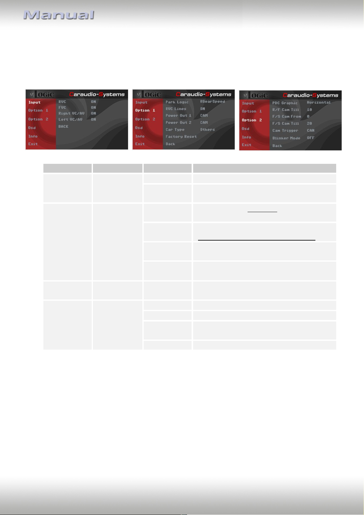
OSD-menu
Menu item
Setting
Explication
Input
FVC
OFF
Front camera deactivated
ON
Switches to front camera if parking process is
enabled and reverse gear is released
Option 1
Park Logic
Intelligent
For vehicles with front-PDC. Enabled while
parking process and up to 20 km/h
RGearOnly
Enabled while parking process
(not suitable for front camera operation)
RGearSpeed
Enabled while parking process and up to
e.g. 10km (speed adjustable)
RGearTime
Enabled while parking process and up to
20 second
Option 2
R/F Cam Till
XX
Speed setting for deactivating of the camera
image
Option 2
PDC Graphic
OFF
OEM PDC display of the vehicle deactivated
Horizontal
Vehicles with horizontal OEM PDC display
Hor. Dark
Vehicles with horizontal OEM PDC display –
alternative presentation
Vertical
Vehicles with vertical OEM PDC display
3.2.1.2. Settings for connecting an after-market front camera
You have to configure some settings in the OSD-menus Inputs, Option 1 and Option 2 if you
want to connect an after-market front camera (Operation of the OSD: see chapter “OSDOperation”).
Note: You can deactivate the camera image by long pressing (2 sec.) the rotation knob.
Version 01.02.2019 V6-MIB
Page 13
Page
12
"
Interface-box
V6C-M655
FRONT
Front camera
V6C-MIB01
harness
+12V power output 1
(12V OUTPUT 1)
R-CAM
AV-1
AV-2
AV-3
V4C-VIDEO
harness
1
2
+12V trigger front camera
(Front-Cam in)
3
1
2
3
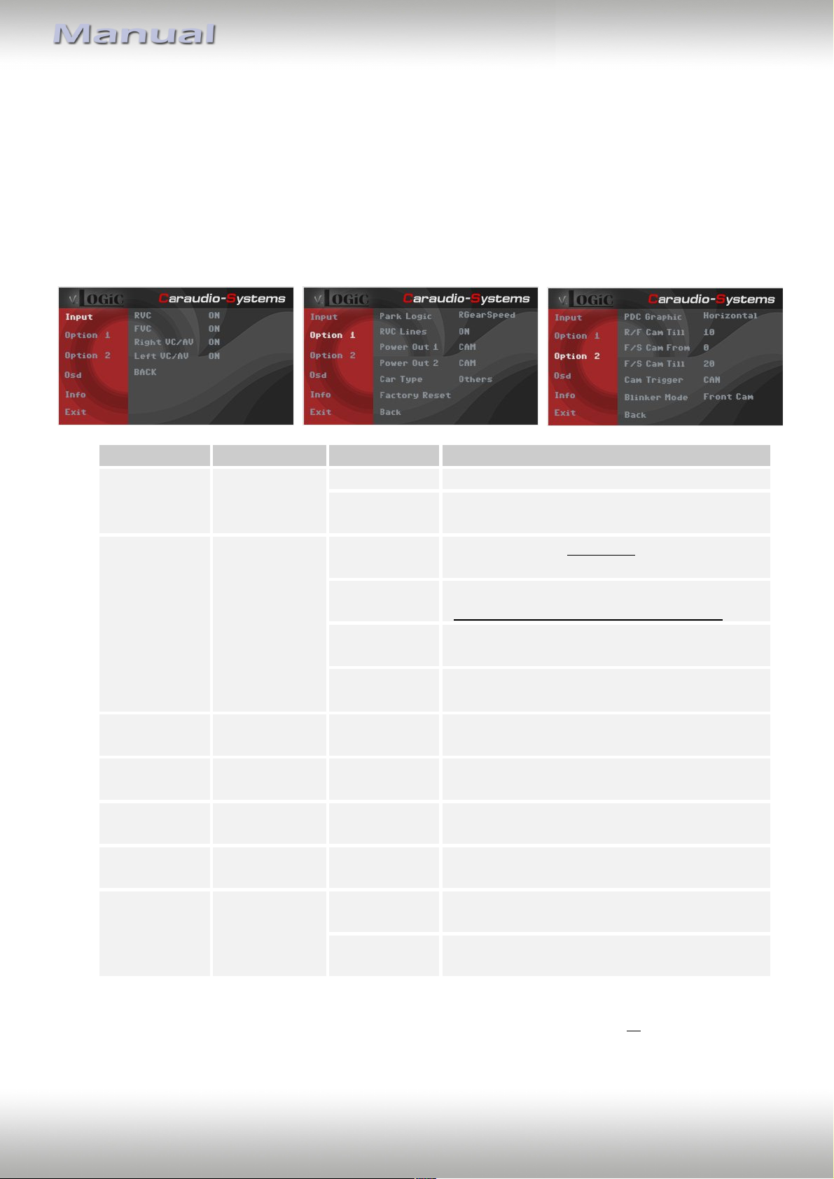
3.2.2. After-market wide view front camera
3.2.2.1. Connection to the after-market wide view front camera
Version 01.02.2019 V6-MIB
Connect the video RCA of the after-market wide view front camera to the female RCA
connector “AV-1” of the V4C-VIDEO harness.
The pink wire (12V OUTPUT 1) of harness V6CMIB01 can be used for +12V electric power supply
(max. 1A) of the after-market front camera.
Configure in the OSD-menu “Option 1”, menu item
“Power Out 1” the setting “CAM” (see also chapter
“Configurable switching outputs”).
Exception: Connect the white/black wire of harness V6C-MIB01 to the right and left
analogue blinker signals (triggered +12V blinker power) and make the menu setting Option 2 / Cam Trigger - „Analogue“, if the system doesn’t switch to the aftermarket
wide view front camera automatically after the described OSD-setup (Option 2 / Cam
Trigger - „CAN“, see next chapter).
Page 14
Page
13
"
OSD-menu
Menu item
Setting
Explication
Input
FVC
OFF
Front camera deactivated
ON
Switches to front camera if parking process is
enabled and reverse gear is released
Option 1
Park Logic
Intelligent
For vehicles with front-PDC. Enabled while
parking process and up to 20 km/h
RGearOnly
Enabled while parking process
(not suitable for front camera operation)
RGearSpeed
Enabled while parking process and up to
e.g. 10km (speed adjustable)
RGearTime
Enabled while parking process and up to
20 second
Option 2
R/F Cam Till
XX
Speed setting for deactivating of the camera
image
Option 2
F/S Cam From
XX
Speed range setting for front- and side
cameras (minimum)
Option 2
F/S Cam Till
XX
Speed range setting for front- and side
cameras (maximum)
Option 2
Blinker Mode
Front Cam
Activation of the front camera image when
the blinker is activated
Option 2
Cam Trigger
CAN
Rear gear and blinker signal detection over
CAN Bus
Analogue
Rear gear and blinker signal detection over
analogue +12V signals
3.2.2.2. Settings for connecting an after-market wide view front camera
For the use of a wide view front camera, the interface offers not only manual activation, but
also activation via the blinker function. Note: via CAN bus blinker signal detection (menu:
Option 2 / Cam Trigger - "CAN“), the activation does not take place in "blinker comfort
mode" (brief touch of the blinker lever).
You have to configure some settings in the OSD-menus Inputs, Option 1 and Option 2 if you
want to connect an after-market front camera (Operation of the OSD: see chapter “OSDOperation”).
Notes: You can deactivate the camera image by long pressing (2 sec.) the rotation knob.
The camera activation via the blinker mode is only available for front camera or for the side
view cameras. A parallel use of this function for all cameras is not possible.
Version 01.02.2019 V6-MIB
Page 15
Page
14
"
Interface-box
V6C-M655
FRONT
V6C-MIB01
harness
V4C-VIDEO
harness
+12V Trigger
right-camera
(Right-Cam in)
+12V Trigger
left-camera
(Left-Cam in)
+12V power output 1
(12V OUTPUT 1)
R-CAM
AV-1
AV-2
AV-3
1
2
3
Right-camera
Left-camera
1
2
3
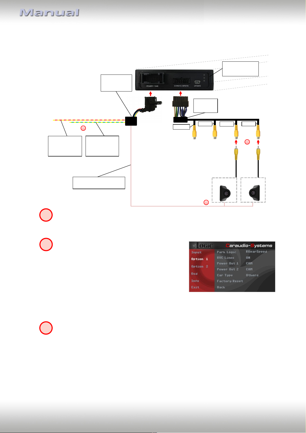
3.2.3. After-market side view cameras
3.2.3.1. Connection of the after-market side view cameras
Connect the video RCA of the right side view camera to the female RCA connector
“AV-2” and the video RCA of the left side view camera to the female RCA connector
“AV-3”of the V4C-VIDEO harness.
The pink wire (12V OUTPUT 1) of harness V6CMIB01 can be used for +12V electric power supply
(max. 1A) of the after-market side cameras.
Configure in the OSD-menu “Option 1”, menu item
“Power Out 1” the setting “CAM” (see also chapter
“Configurable switching outputs”).
Exception: Connect the yellow/red wire to the right analogue blinker signal and the
yellow/green wire to the left analogue blinker signal of harness V6C-MIB01 (triggered
+12V blinker power) and make the menu setting - Option 2 / Cam Trigger „Analogue“, if the system doesn’t switch to the aftermarket side view camera
automatically after the described OSD-setup (Option 2 / Cam Trigger - „CAN“, see
next chapter).
Version 01.02.2019 V6-MIB
Page 16
Page
15
"
OSD-menu
Menu item
Setting
Explication
Input
Right VC
ON
Right camera input activated
Left VC
ON
Left camera input activated
Option 1
Park Logic
Intelligent
For vehicles with front-PDC. Enabled while
parking process and up to 20 km/h
RGearOnly
Enabled while parking process
(not suitable for front camera operation)
RGearSpeed
Enabled while parking process and up to
e.g. 10km (speed adjustable)
RGearTime
Enabled while parking process and up to
20 second
Option 2
R/F Cam Till
XX
Speed setting for deactivating of the camera
image
Option 2
F/S Cam From
XX
Speed range setting for front- and side
cameras (minimum)
Option 2
F/S Cam Till
XX
Speed range setting for front- and side
cameras (maximum)
Option 2
Blinker Mode
Side Cam
Activation of the side view cameras image
when the blinker is activated
Option 2
Cam Trigger
CAN
Rear gear and blinker signal detection over
CAN Bus
Analogue
Rear gear and blinker signal detection over
analogue +12V signals
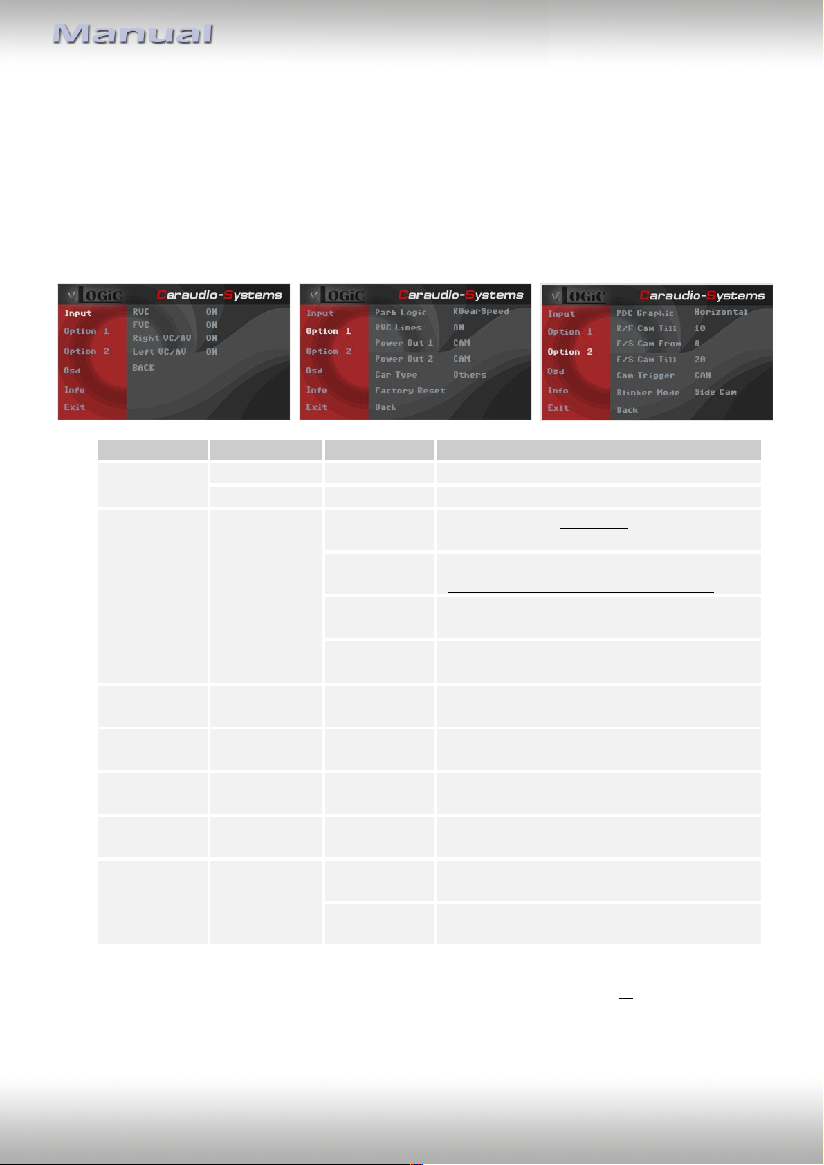
3.2.3.2. Settings for connecting of after-market side view cameras
For the use of side view cameras, the interface offers not only manual activation, but also
activation via the blinker function. Note: via CAN bus blinker signal detection (menu: Option
2 / Cam Trigger - "CAN“), the activation does not take place in "blinker comfort mode" (brief
touch of the blinker lever).
You have to configure some settings in the OSD-menus Inputs, Option 1 and Option 2 if you
want to connect an after-market front camera (Operation of the OSD: see chapter “OSDOperation”).
Notes: You can deactivate the camera image by long pressing (2 sec.) the rotation knob.
The camera activation via the blinker mode is only available for front camera or for the side
view cameras. A parallel use of this function for all cameras is not possible.
Version 01.02.2019 V6-MIB
Page 17
Page
16
"
Rear-view
camera
Interface-box
V6C-M655
FRONT
+12V Rear gear signal
input (R-Cam in)
V6C-MIB01
harness
R-CAM
AV-1 AV-2
AV-3
+12V power output 2
(12V OUTPUT 2)
V4C-VIDEO
harness
1
2
3
1
2
3
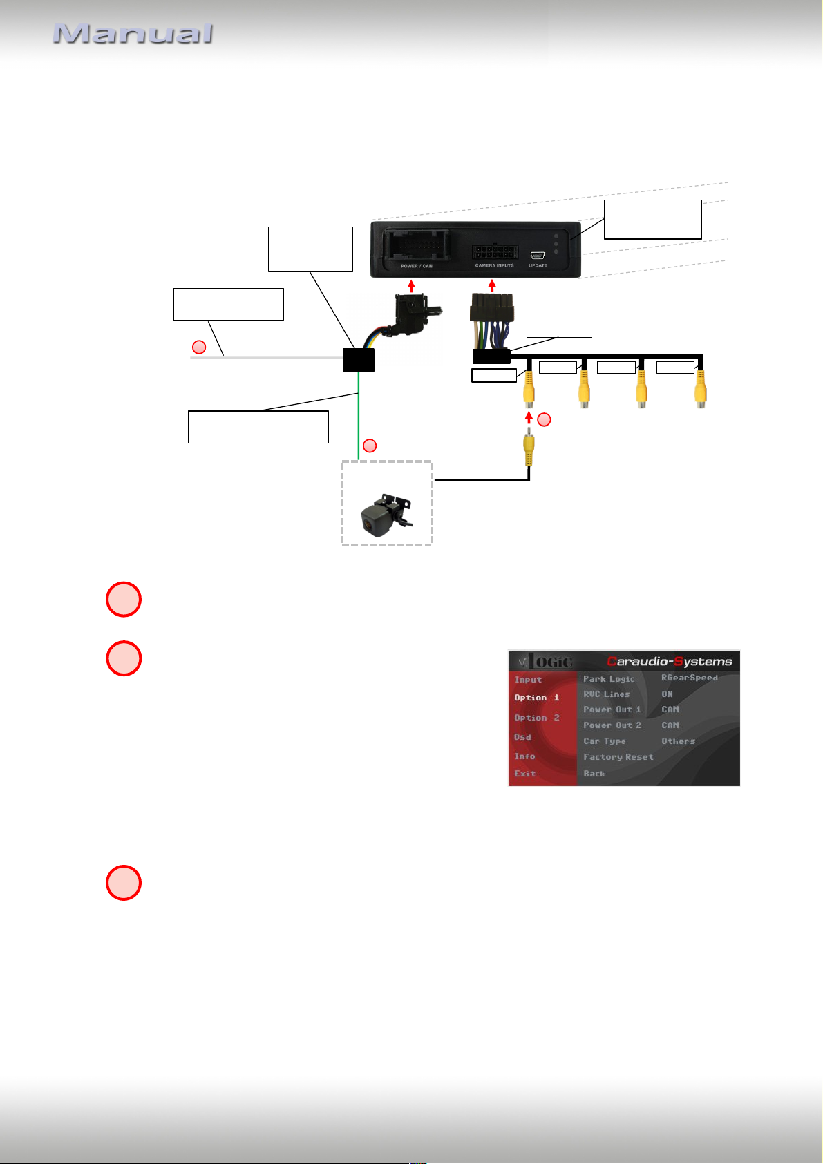
3.2.4. After-market rear-view camera
3.2.4.1. Connection to the after-market rear-view camera
Connect the video RCA of the after-market rear-view camera to the female RCA
connector “R-CAM” of the V4C-VIDEO harness.
The green wire (12V OUTPUT 2) of harness V6CMIB01 can be used for +12V electric power supply
(max. 1A) of the after-market rear-view camera.
Configure in the OSD-menu “Option 1”, menu item
“Power Out 2” the setting “CAM” (see also chapter
“Configurable switching outputs”).
Exception: Connect the white wire of harness V6C-MIB01 to analogue rear gear
signal (+12V) and make the menu setting - Option 2 / Cam Trigger - „Analogue“, if the
system doesn’t switch to the aftermarket rear-view camera automatically after the
described OSD-setup (Option 2 / Cam Trigger - „CAN“, see next chapter).
Version 01.02.2019 V6-MIB
Page 18
Page
17
"
OSD-menu
Menu item
Setting
Explication
Input
RVC
OFF
Rear-view camera deactivated
ON
Switches to rear-view camera if reverse gear
is engaged or PDC is activate
Option 1
Park Logic
Intelligent
For vehicles with PDC. Enabled while parking
process and up to 20 km/h (not suitable for
front camera operation for vehicles without
front-PDC)
RGearOnly
Enabled while parking process
(not suitable for front camera operation)
RGearSpeed
Enabled while parking process and up to
e.g. 10km (speed adjustable)
RGearTime
Enabled while parking process and up to
20 second
Option 1
RVC Lines
ON
Interactive lane lines activated
Option 2
R/F Cam Till
XX
Speed setting for deactivating of the camera
image
Option 2
PDC Graphic
OFF
OEM PDC display of the vehicle deactivated
Horizontal
Vehicles with horizontal OEM PDC display
Hor. Dark
Vehicles with horizontal OEM PDC display –
alternative presentation
Vertical
Vehicles with vertical OEM PDC display
Option 2
Cam Trigger
CAN
Rear gear and blinker signal detection over
CAN Bus
Analogue
Rear gear and blinker signal detection over
analogue +12V signals
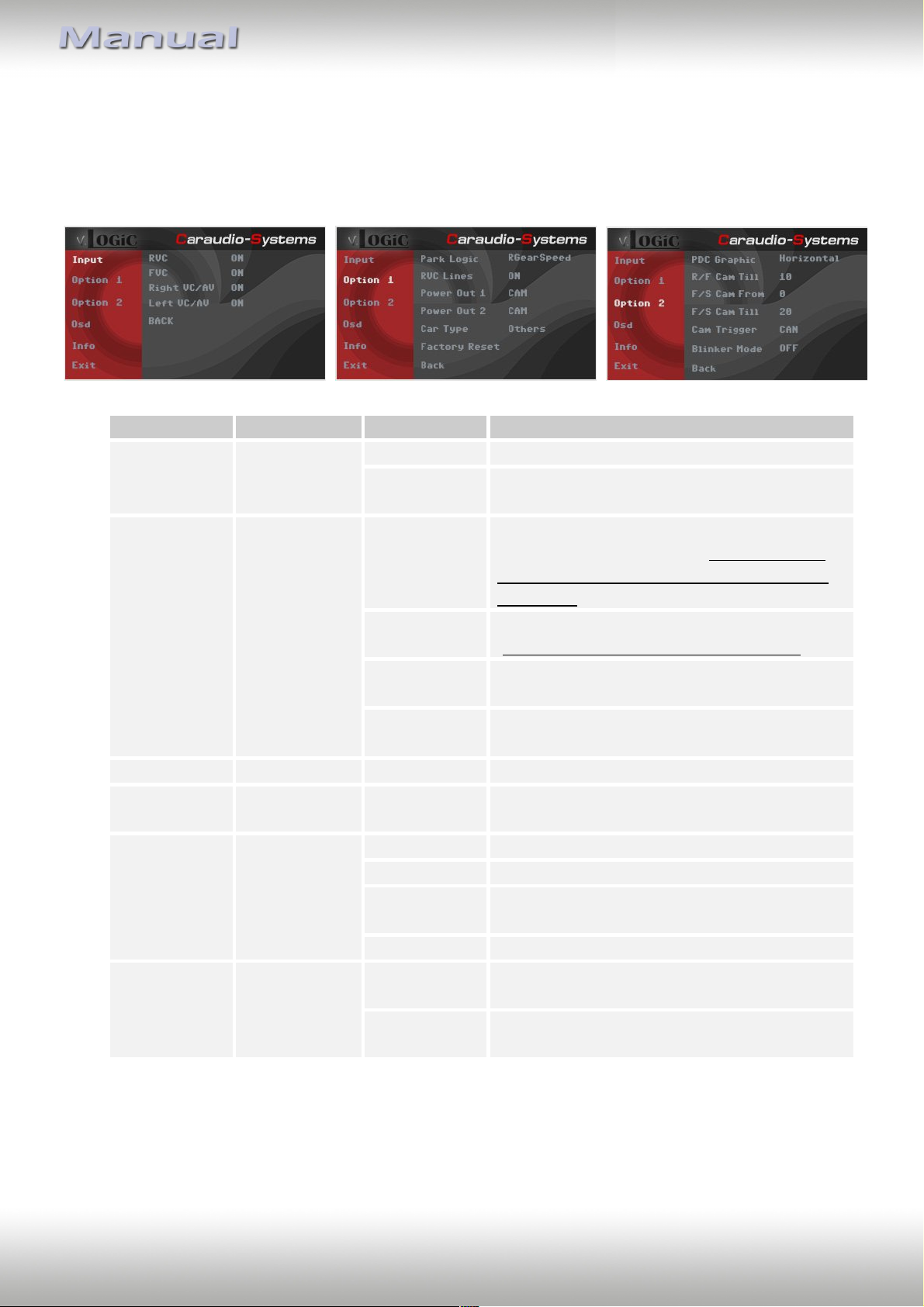
3.2.4.2. Settings for connecting an after-market rear-view camera
You have to configure some settings in the OSD-menus Inputs, Option 1 and Option 2 if you
want to connect an after-market rear-view camera (Operation of the OSD: see chapter
“OSD-Operation”).
Note: You can deactivate the camera image by long pressing (2 sec.) the rotation knob.
Version 01.02.2019 V6-MIB
Page 19
Page
18
"
OSD-menu
Menu item
Setting
Explication
Input
RVC
OEM
If a factory rear-view camera is existing!
The interface turns off, if reverse gear is
enabled and it displays factory rear-view
camera
Option 1
Park Logic
Intelligent
For vehicles with front-PDC. Enabled while
parking process and up to 20 km/h
RGearSpeed
Enabled while parking process and up to
e.g. 10km (speed adjustable)
RGearTime
Enabled while parking process and up to
20 second
Option 2
R/F Cam Till
XX
Speed setting for deactivating of the camera
image
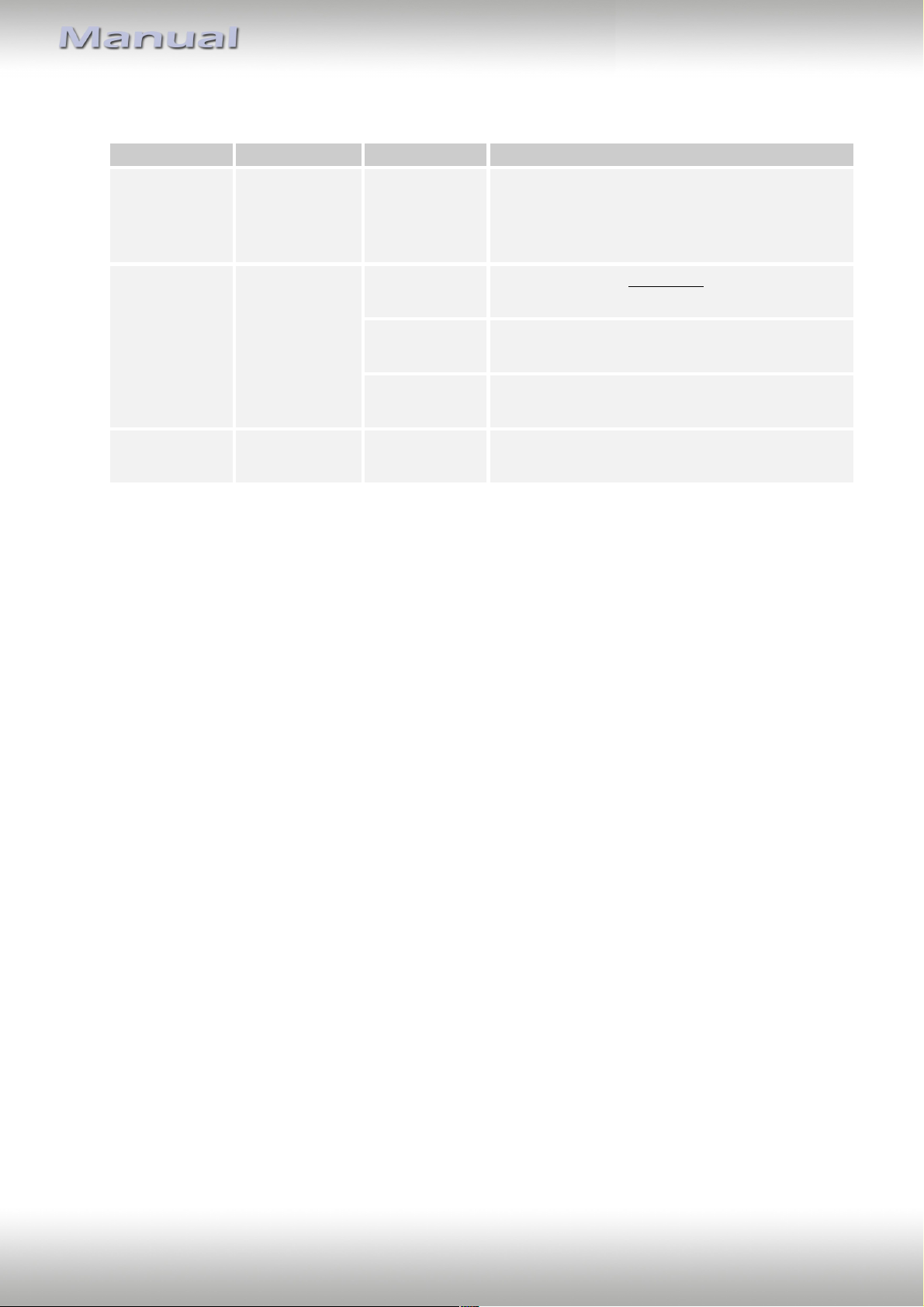
3.2.4.3. Settings for OEM rear-view camera
Version 01.02.2019 V6-MIB
Page 20
Page
19
"
Interface-box
V6C-M655
FRONT
V6C-MIB01
harness
+12V power output 1
(12V OUTPUT 1)
R-CAM
AV-1
AV-2
AV-3
V4C-VIDEO
harness
1
2
AV-source
AV source control
(AV2 / AV3)
IR-control cable
STA-xxx (optional)
3
1
2
3
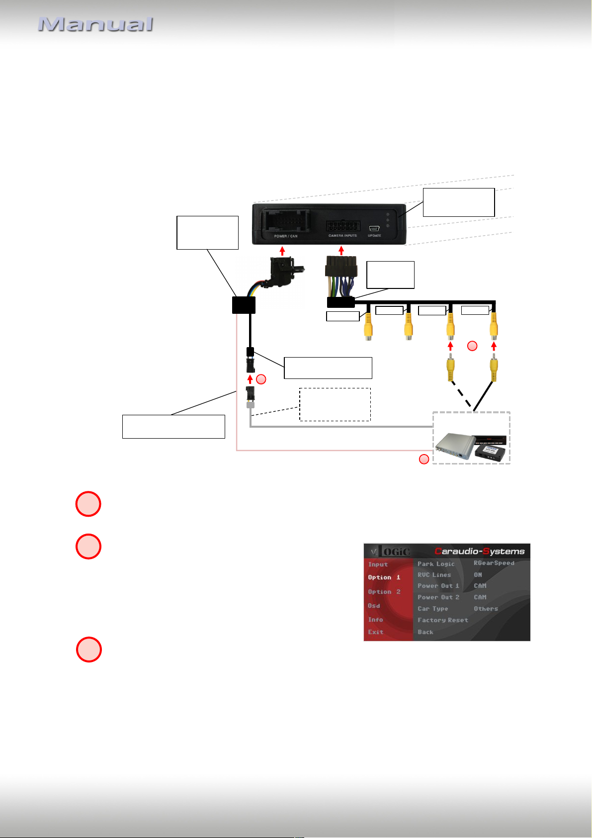
3.2.5. AV source
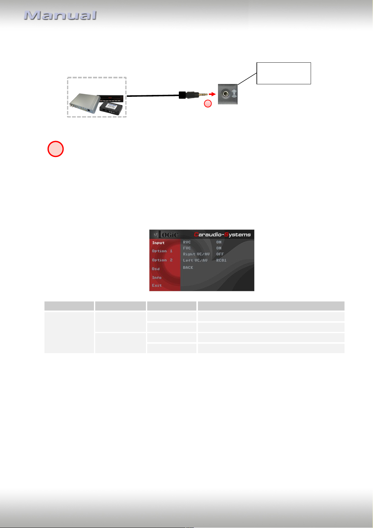
The AV-3 or AV-2 input can alternatively be used for AV source connection. In addition, the
interface has the option of controlling the connected compatible AV source over the
touchscreen / control knob.
3.2.5.1. AV source video connection
Connect video RCA of AV source to female RCA connector "AV-3" or "AV-2" of the
video harness V4C-VIDEO.
The pink wire (12V OUTPUT 1) of harness V6CMIB01 can be used for +12V electric power supply
(max. 1A) of the AV source. Configure in the OSDmenu “Option 1”, menu item “Power Out 1” the
setting “AVS” or “ACC” (see also chapter
“Configurable switching outputs”).
Optional: Using the respective STA-xxx IR-control cable (available separately),
interconnect the female 3pin AMP connector of harness V6C-MIB01 and the IR-port
of the AV source.
Version 01.02.2019 V6-MIB
Page 21
Page
20
"
Vehicle AUX input
1
AV-source
OSD-menu
Menu item
Setting
Explication
Input
Right VC/AV
OFF
No camera / AV source connected
RCxx
AV source connected to the AV-2 input
Left VC/AV
OFF
No camera / AV source connected
RCxx
AV source connected to the AV-3 input
1
3.2.5.2. AV source audio connection
Connect the audio output of the AV source to the vehicle AUX input.
3.2.5.3. Settings for connecting an AV source
You have to configure some settings in the OSD-menu Input if you want to connect an AV
source (Operation of the OSD: see chapter “OSD-Operation”).
Note: Select "RC01" if AV source control function via touchscreen / control knob is not used.
Version 01.02.2019 V6-MIB
Page 22
Page
21
"
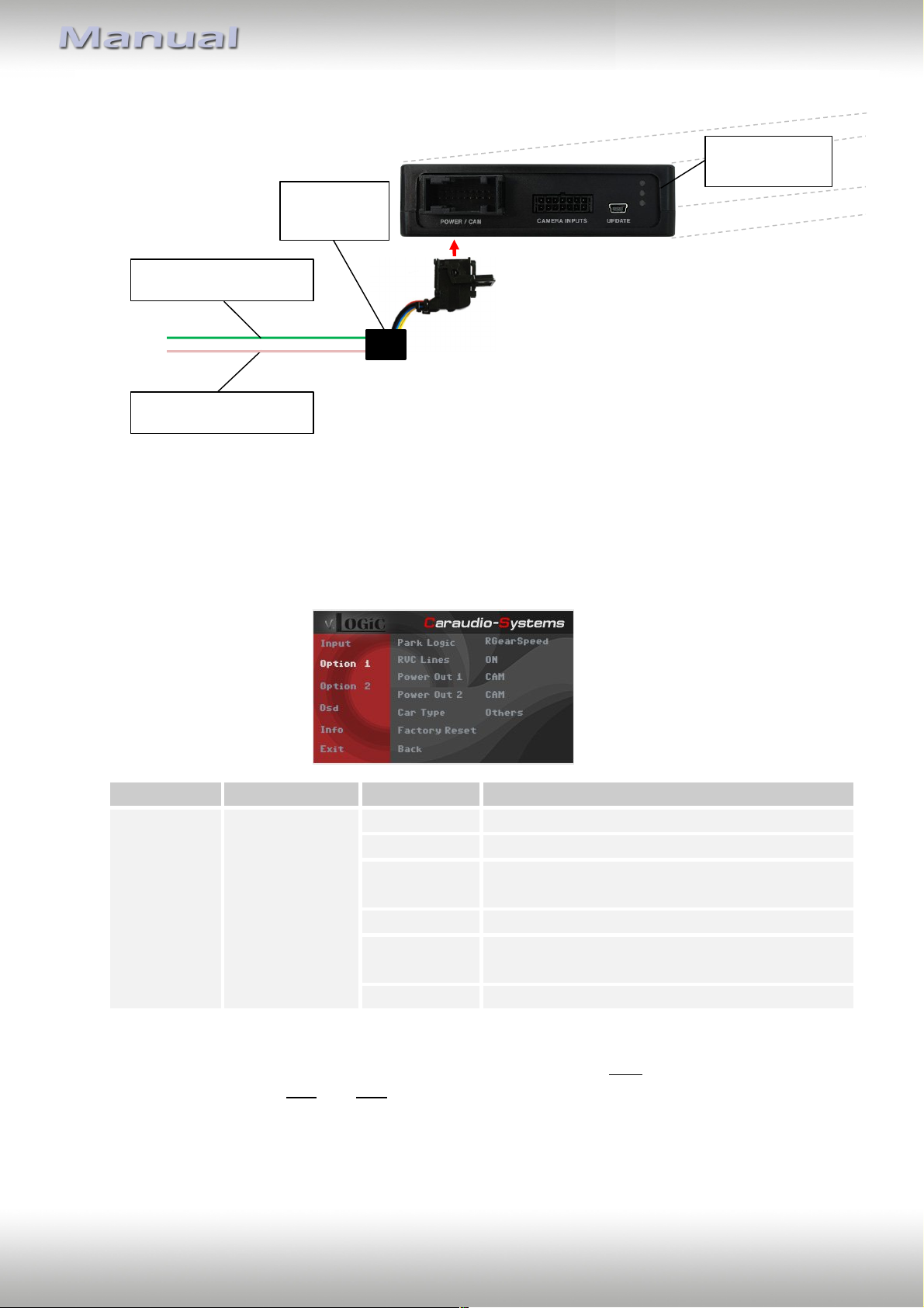
Interface-box
V6C-M655
FRONT
V6C-MIB01
harness
+12V power output 1
(12V OUTPUT 1)
+12V power output 2
(12V OUTPUT 2)
OSD-menu
Menu item
Setting
Explication
OPTION
Power Out 1
(pink)
Power Out 2
(green)
CAN
+12V when the interface is on (red LED on)
ACC
+12V when ignition is on
Cam
+12V when camera input is activated
(manually or automatically)
RGear
+12V when reverse gear is engaged
AVS
+12V when camera / video input was manually
activated
OFF
Trigger output deactivated
3.2.6. Configurable trigger outputs
You can configure the both +12V trigger outputs separately. The pink wire is (12V
OUTPUT 1) is Power Out 1 and the green wire is (12V OUTPUT 2) is Power Out 2.
Note: You can configure the both trigger outputs in the OSD-menu Option 1 separately
(Operation of the OSD: see chapter “OSD-Operation”).
Tip: We recommend for all camera modes the power out setting “Cam” and for AV source
the power out setting “AVS” or “ACC”.
Version 01.02.2019 V6-MIB
Page 23
Page
22
"
OSDmenu
Menu
item
Setting
Explication
Option 1
RVC Lines
OFF
Interactive lane lines
deactivated
ON
Interactive lane lines
activated
Car Type
AUDI_A3/AUDI_A4/
AUDI_Q7/PASSAT/GOLF_7/
CAYENNE/911/Boxster/Cayman/Others
Vehicle type selection
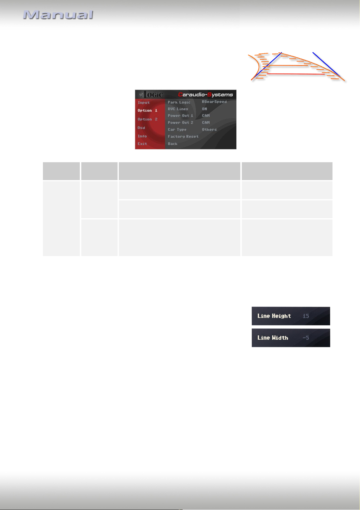
3.3. Interactive lane lines
You have to configure some settings in the OSD menu
Option 1 if you want to activate interactive lane lines
(Operation of the OSD: see chapter “OSD-Operation”).
3.3.1. Interactive lane lines settings
The height and width of the interactive lane lines can be set in the
OSD menu. For this setting you must at first activate the rear-view
camera level and push then the „MENU“/„HOME“(Porsche) button
for 2sec. to activate the settings menu. With the rotation knob you
can select the menu point "Line Height" to change the height of the
interactive lane lines and with menu point "Line Width" the width
of the lines. Over the menu point "Exit" you can leave this settings
menu.
Version 01.02.2019 V6-MIB
Page 24
Page
23
"
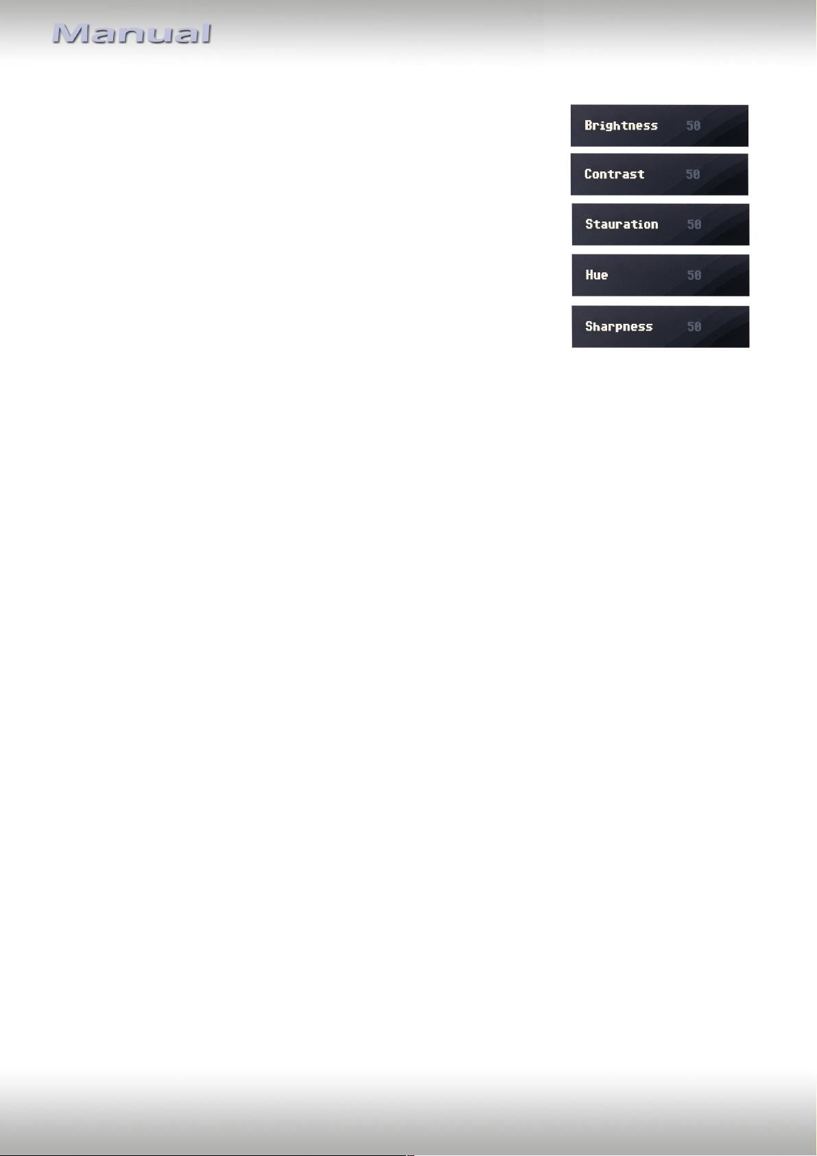
3.4. Picture settings
The camera picture settings can be set in the OSD menu.
For this setting you must at first activate the camera level
and push then the „MENU“/„HOME“(Porsche) button for
2sec. to activate the settings menu. With the rotation knob
you can select and change the "Brightness", "Contrast",
"Saturation", Hue" and "Sharpness" menu points.
Over the menu point "Exit" you can leave this settings menu.
Note: The picture settings will be retained for every camera input separately.
Version 01.02.2019 V6-MIB
Page 25
Page
24
"
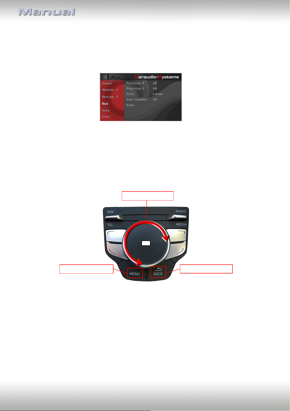
OK
Options
Long press = enter OSD
Short press = leave OSD
4. Operation
4.1. Main OSD On-screen display
You can change the basic configurations of the interface in the OSD (on screen display).
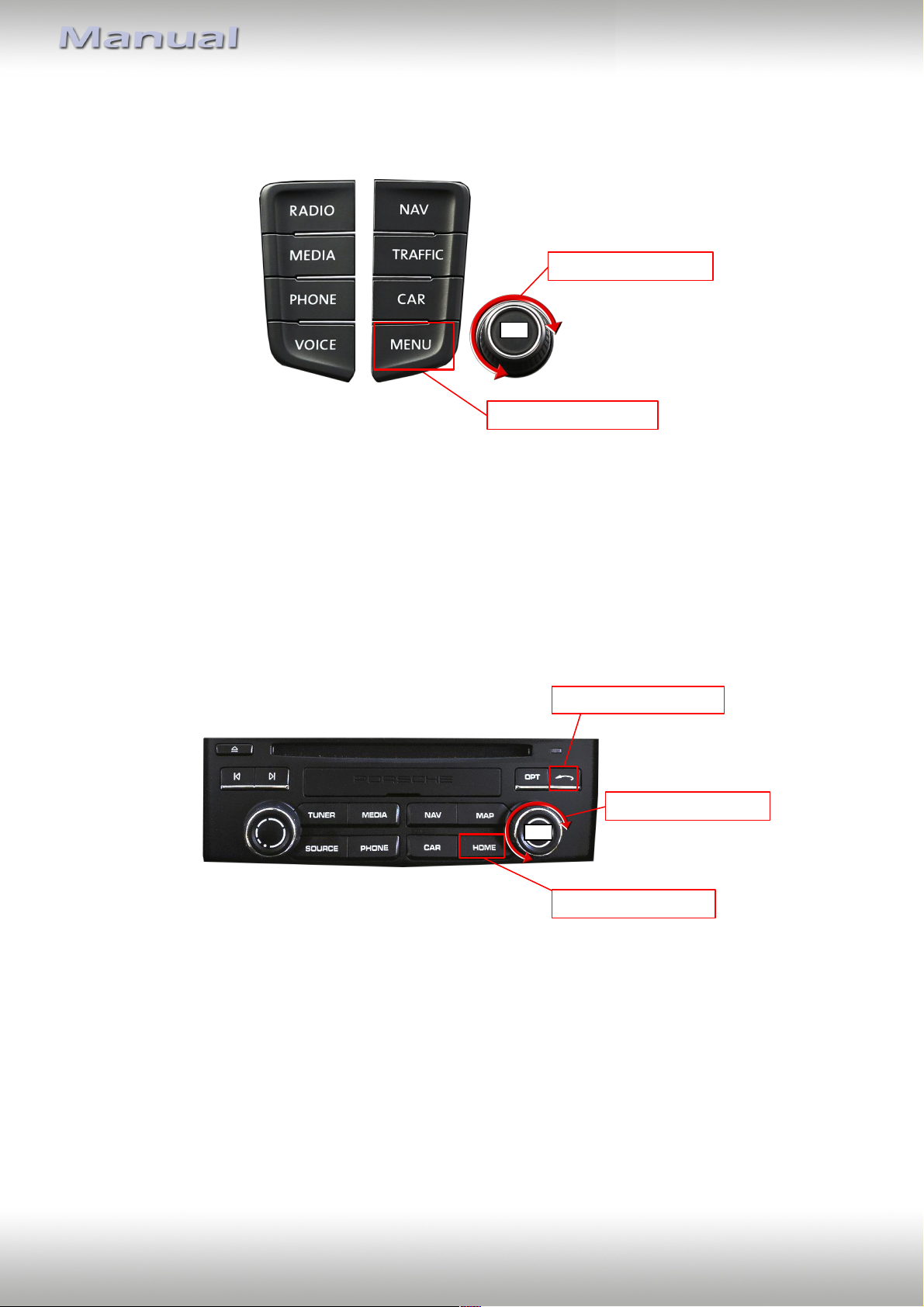
4.1.1. OSD – Operation
The OSD menu can be controlled via the following buttons:
4.1.1.1. Audi OSD control
Version 01.02.2019 V6-MIB
Page 26
Page
25
"
Long press = enter OSD
Options
OK
Options
OK
Long press = enter OSD
Short press = leave OSD
4.1.1.2. VW / Skoda OSD control
4.1.1.3. Porsche OSD control
Version 01.02.2019 V6-MIB
Page 27
Page
26
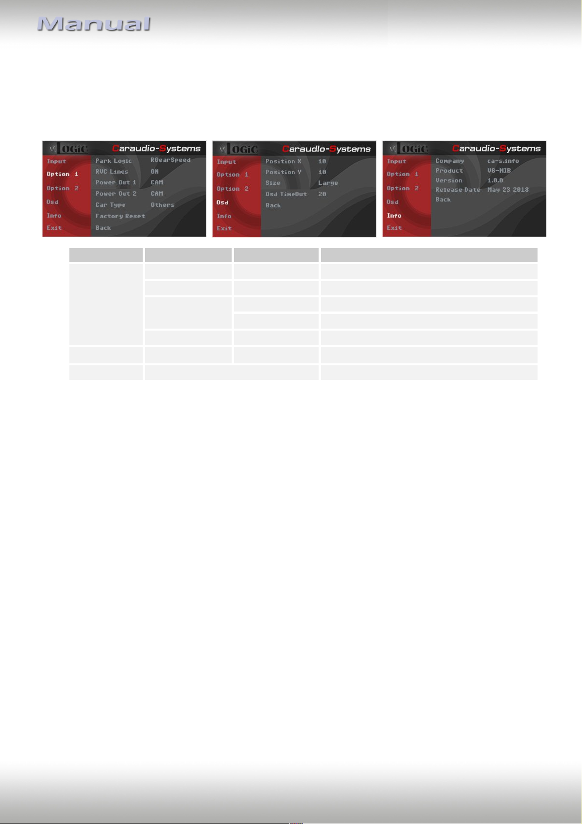
"
OSD-menu
Menu item
Setting
Explication
Osd
POS. X
0-xxx
Horizontal position of the OSD
POS. Y
0-xxx
Vertical position of the OSD
Size
Small
Small OSD menu windows
Large
Large OSD menu windows
Osd TimeOut
2-20
Time setting for automatic OSD shutoff
Info
Version
X.XX.XX
Displays the current SW-version
Option 1
Factory Reset
Resetting to factory settings
4.1.2. OSD – Additional setting options
The following settings in the OSD menus Option 1 and OSD can be configured over and
above the described settings in this manual (Operation of the OSD: see chapter “OSDOperation”):
Version 01.02.2019 V6-MIB
Page 28
Page
27
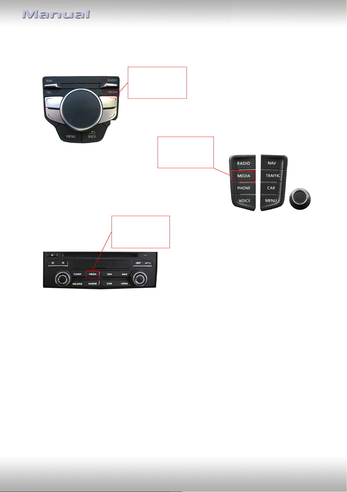
"
Long press = enter / leave
interface camera level
Short press = switch camera
video inputs
Long press = enter / leave
interface camera level
Short press = switch camera
video inputs
Long press = enter / leave
interface camera level
Short press = switch camera
video inputs
4.2. Selecting the interface as current video source
In the vehicle’s Media menu, activate AUX level (only necessary for AV source operation)
and press long “MEDIA” button to choose the interface as current video source.
Short press ”MEDIA” button (or additionally on touchscreen the swipe gesture) switch the
video sources (cameras/AV source). Each short press will switch to the next enabled input. If
all inputs are enabled the order is:
Rear CAM à Front CAM à Right Cam/AV à Left Cam/AV à …
Inputs which are not enabled are skipped.
The exiting of the video interface level is achieved by long press of “MEDIA” button or by
short press of “RADIO/TUNER/NAV/MAP/TEL/PHONE/SOURCE/CAR” (MIB system specific)
button.
Version 01.02.2019 V6-MIB
Page 29
Page
28
"
4.3. Assigning device controls
You can assign the device controls in the OSD-menu
Input (Operation of the OSD: see chapter “OSDOperation”). Assign related IR-codes for Left VC/AV or
Right VC/AV input as described in device control table
(see appendix A).
Note: Select "RC01" if AV source control function via touchscreen / control knob is not used.
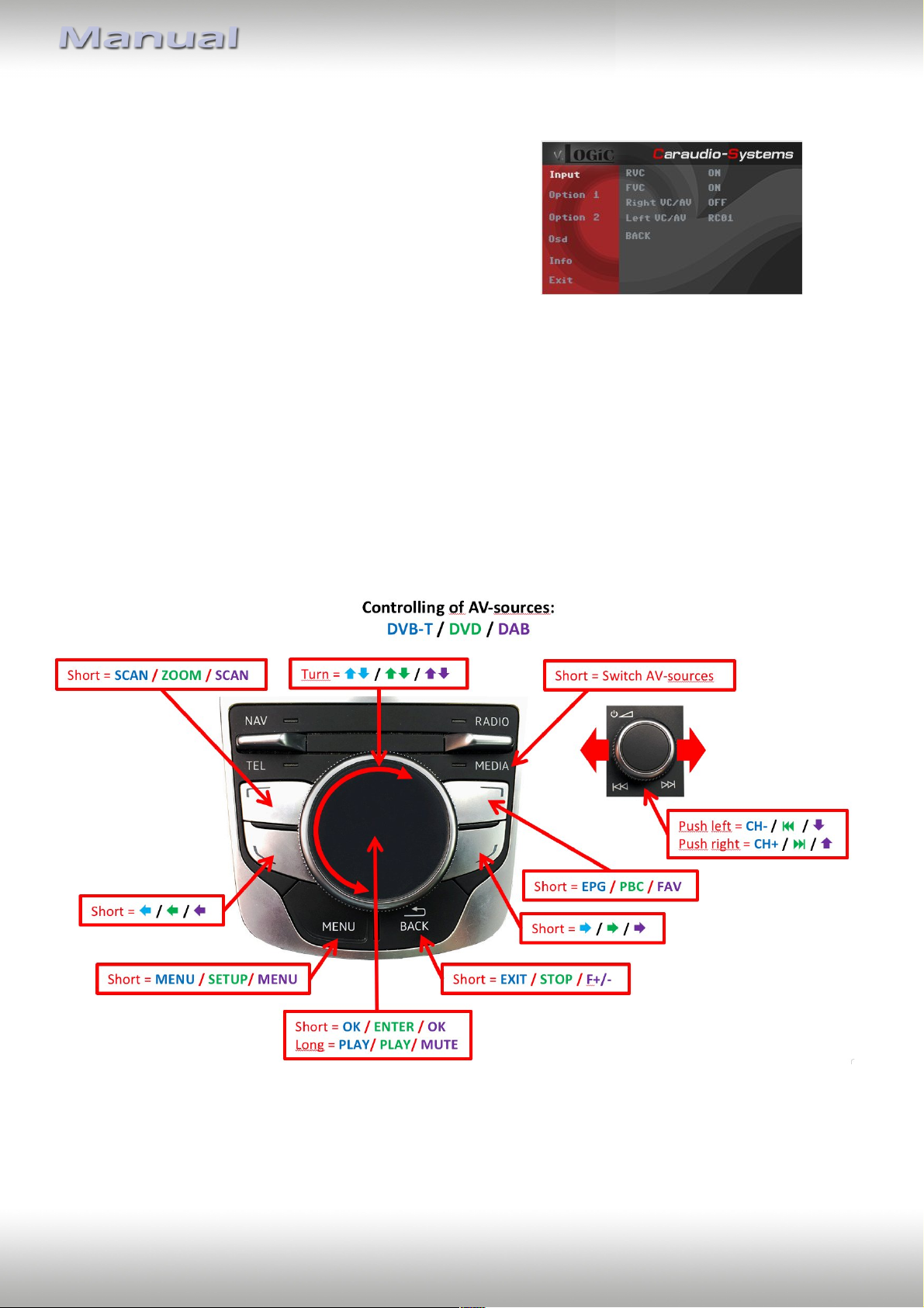
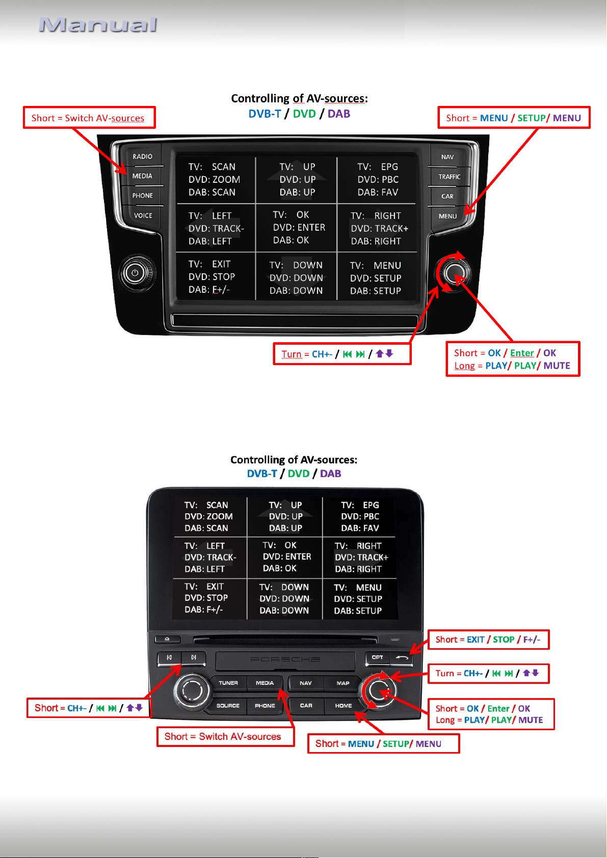
4.4. Controlling of the connected AV source
The picture shows which functions of the connected devices can be executed by touch
screen / control knob. Once an AV-input is activated the touchscreen control knob action will
execute the function described in the picture. The function description equals the remote
control buttons of the device’s remote control. On the additional device the writing on the
remote control buttons may vary (e.g. AV instead of Source).
4.4.1. Audi AV source control
Note: A few functions could be different on some connected devices.
Version 01.02.2019 V6-MIB
Page 30
Page
29
"
4.4.2. VW / Skoda AV source control
Note: A few functions could be different on some connected devices.
4.4.3. Porsche AV source control
Note: A few functions could be different on some connected devices.
Version 01.02.2019 V6-MIB
Page 31
Page
30
"
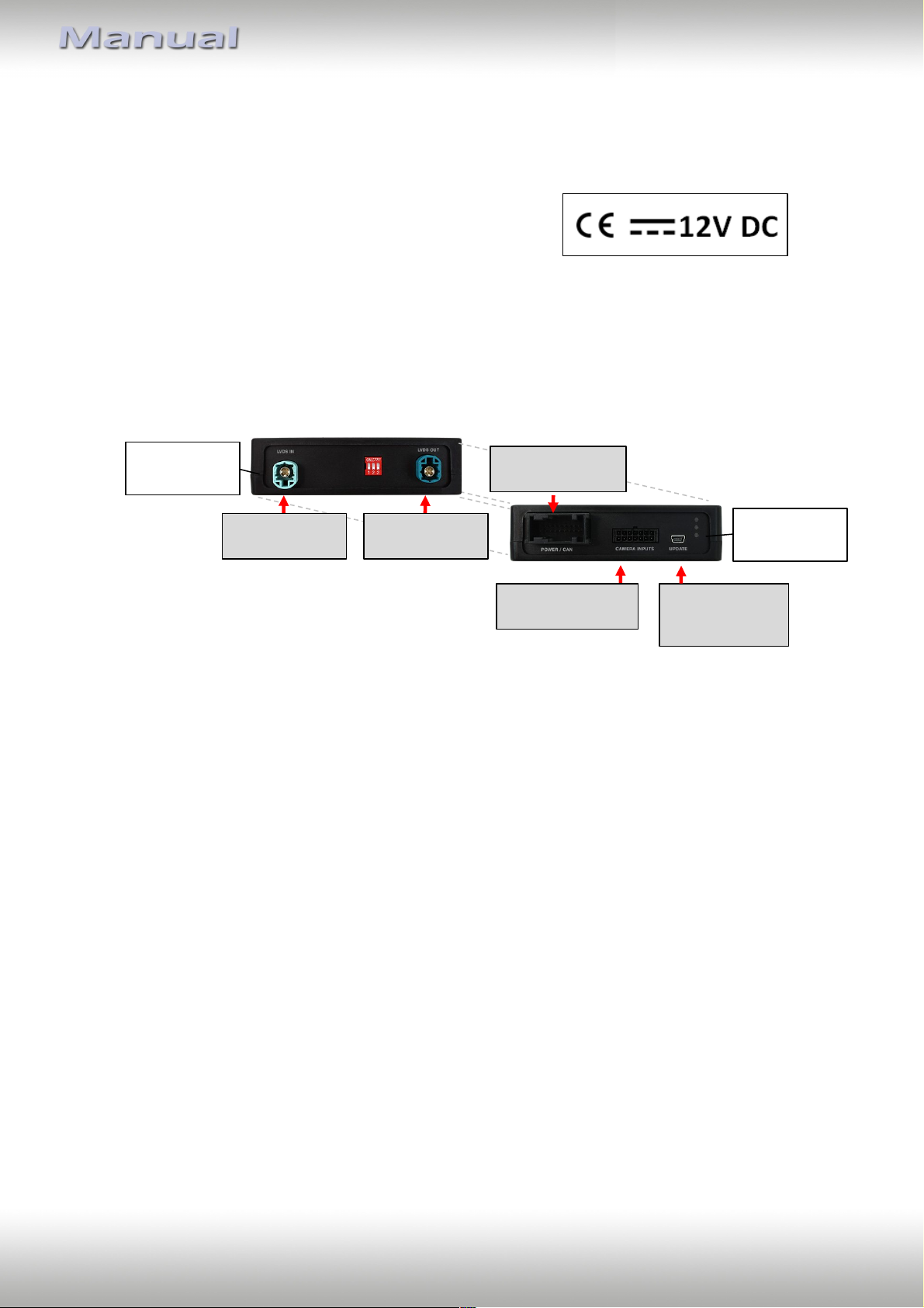
Interface-box
V6C-M655
REAR
Male 4pin HSD
LVDS connector
Male 18pin AMP
connector
Female
update-connector
Mini USB
Interface-box
V6C-M655
FRONT
Male 4pin HSD
LVDS connector
Male 14pin
Micro-Fit connector
5. Specifications
Operation voltage 10.5 – 14.8V DC
Stand-by power drain 1mA
Operation power drain 190mA
Power consumption 2,6W
Temperature range -20°C to +80°C
Weight (box only) 285g
Measurements (box only) B x H x T 141 x 30 x 105 mm
6. Connections (interface-box)
7. Technical Support
Caraudio-Systems Vertriebs GmbH
manufacturer/distribution
In den Fuchslöchern 3
D-67240 Bobenheim-Roxheim
Legal disclaimer: Mentioned company and trademarks, as well as product names/codes are registered
trademarks ® of their corresponding legal owners.
email [email protected]
Version 01.02.2019 V6-MIB
 Loading...