

Page 1
TV-Free
Universal video-in-motion Interface
TF-U500
Non p and p version for high speed CAN
Legal Information
By law, watching moving pictures while driving is prohibited, the driver must not be
distracted. We do not accept any liability for material damage or personal injury resulting,
directly or indirectly, from installation or operation of this product. This product should only
be used while standing or to display fixed menus or rear-view-camera video when the
vehicle is moving, for example the MP3 menu for DVD upgrades.
Changes/updates of the vehicle’s software can cause malfunctions of the interface. We
offer free software-updates for our interfaces for one year after purchase. To receive a free
update, the interface must be sent in at own cost. Labor cost for and other expenses
involved with the software-updates will not be refunded.
Version 21.08.2020 TF-U500
Page 2

Page
1
"
CAN-box TV-500
HW_____ SW_____
Harness
TV-UNI
Take down the SW-version and HW-version of the interface-boxes, and store this
manual for support purposes!
Contents
1. Prior to installation
1.1. Delivery contents
1.2. Pin-assignments
1.3. Dip switch functions of the TV-500
2. Installation
3. Specifications
4. Technical support
1. Prior to installation
Read the manual prior to installation. Technical knowledge is necessary for installation. The
place of installation must be free of moisture and away from heat sources.
1.1. Delivery contents
With USB update-port for software-updates by consumer!
Version 21.08.2020 TF-U500
Page 3

Page
2
"
Cable colour
Pin-No.
Assignment
● Yellow
Pin 4
CAN-HIGH – connection to the head-unit
● Blue
Pin 3
CAN-LOW – connection to the head-unit
●● Yellow/Black
Pin 8
CAN-HIGH – connection to the vehicle
●● Blue/Black
Pin 7
CAN-LOW – connection to the vehicle
● Red
Pin 1
+12V permanent
● Black
Pin 5
Ground
● Green
Pin 6
Activation of the video-in-motion function
(+12V = TV-free activated)
● White
Pin 2
Trigger output (+12V DC 500mA)
Pin-assignment male 8pin connector of TV-500
1.2. Pin-assignments
Pin-assignment harness TV-UNI
1.3. Dip switch functions of the TV-500
Dip 1 – activation TV-free
Dip 2 – no function (in some vehicles for rear-view camera)
Dip 3 – no function
Dip 4 – no function
Dip 5 – CAN-bus termination resistor on the vehicle side
Dip 6 – CAN-bus termination resistor on the head-unit side
Version 21.08.2020 TF-U500
Page 4

Page
3
"
2. Installation
Switch off ignition and disconnect the vehicle’s battery! If according to factory rules
disconnecting the battery has to be avoided, it is usually sufficient to put the vehicle in
sleep-mode. In case the sleep-mode does not show success, disconnect the battery with a
resistor lead.
Install the interface at the CAN bus connection of the respective navigation system. Separate
the two CAN BUS cables (CAN-HIGH and CAN-LOW) from the navigation system and connect
them to harness TV-UNI (see picture below).
Connect the red wire to +12V permanent and connect the black wire to ground.
The video-in-motion can be activated and deactivated by Dip 1 or alternatively by the
included loose green cable in connection with a switch (not included in delivery).*
Video-in-motion permanent
With dip1 to ON the video-in-motion function is activated permanently without disturbing
the navigation performance.
Video-in-motion selective
With dip1 to OFF the included green cable is used to activate the video-in-motion function.
Connect a switch to the green cable and connect the green cable to +12V ACC.
● +12V = TV-Free is activated
● 0V = TV-Free is not activated
Note: The loose white cable is not required and must be isolated.
*Exception: On vehicles/navigation systems with Dip 1 must be set to OFF and video-inmotion activation performs selectively by vehicle button, the activation by green cable
isn’t possible!
Version 21.08.2020 TF-U500
Page 5

Page
4
"
Vehicle/ navigation
Dip 1
Dip 2
Dip 3
Dip 4
Dip 5
Dip 6
Navi Plus RNS-E
OFF
OFF
OFF
OFF
OFF
OFF
Cable colour
Assignment
●● Red/Yellow
+12Volt Permanent 15
● Brown
Ground Pin 12
●● Orange/Green
CAN HIGH Pin 9
●● Orange/Brown
CAN LOW Pin 10
Compatible vehicles Audi A3, A4, TT (8J)
Attention! Audi A6 with Navi Plus RNS-E have analog speed signal.
Vehicles with Audi Navi Plus RNS-E
Place of installation is at the back side of the navigation unit.
No liability for vehicle wire colors and pin definition!
Possible changes by the vehicle manufacturer. The given
information must be verified by the installer.
Longpress the „>|“ button (about 5 seconds) to
activate/deactivate thevideo-in-motion function. When
ignition is off, the video-in-motion interface will be
automatically disabled.
Long blinking of the navigations backlight = TV Free ON
Short blinking of the navigations backlight = TV Free OFF
Note: While the video-in-motion function is activated, the navigation performance is not
possible!
Version 21.08.2020 TF-U500
Page 6

Page
5
"
Vehicle/navigation
Dip 1
Dip 2
Dip 3
Dip 4
Dip 5
Dip 6
MMI - MIB
ON
OFF
OFF
OFF
ON
ON
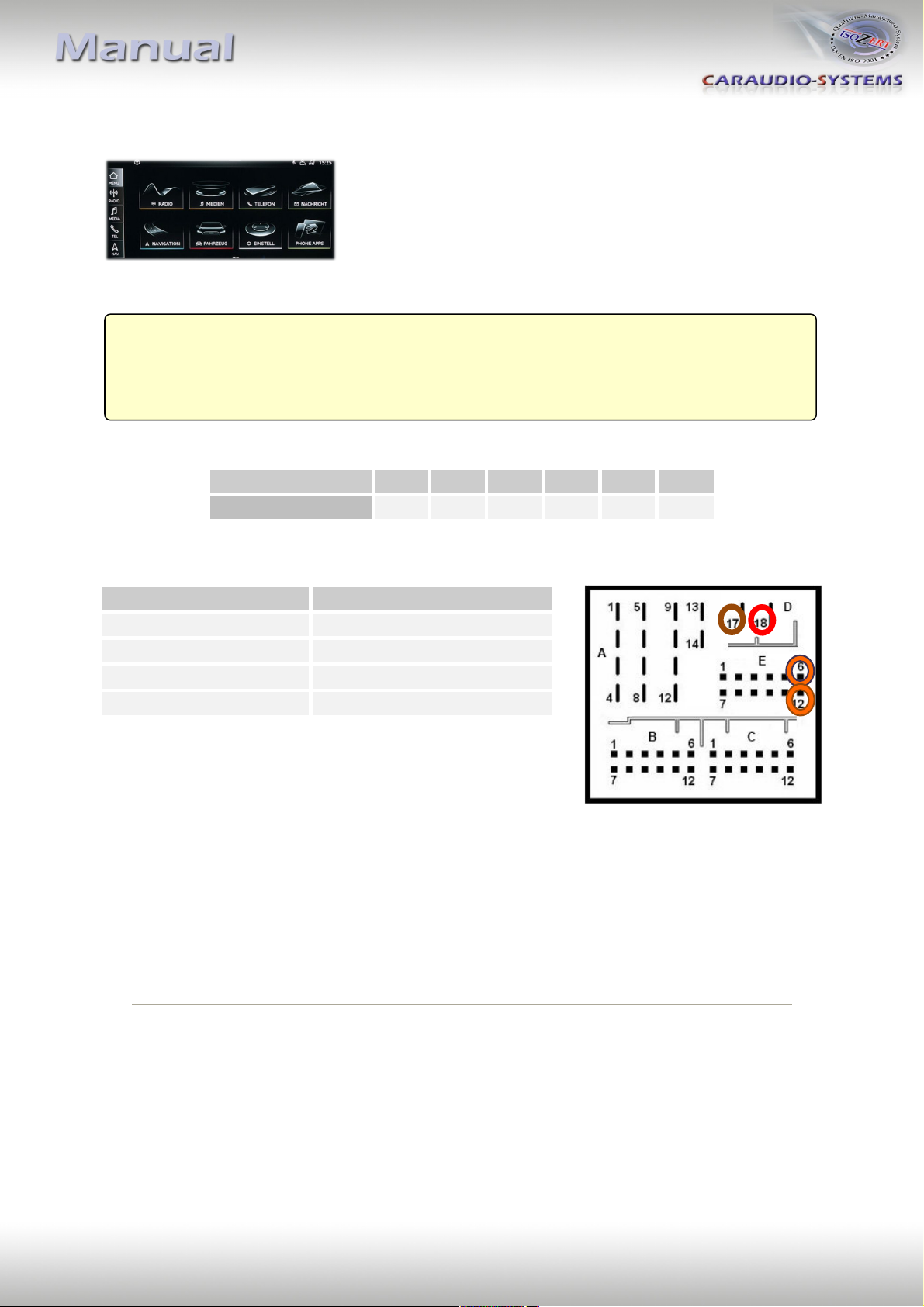
Cable colour
Assignment
● Red
+12V permanent Pin 18
● Brown
Ground Pin 17
●● Orange/Violet
CAN HIGH Pin 6
●● Orange/Brown
CAN LOW Pin 12
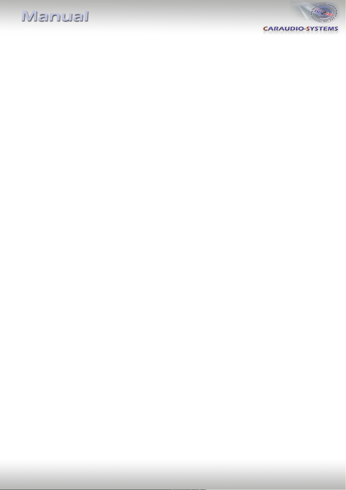
Compatible vehicles Audi
Navigation Navigation plus with MMI touch 7”
Vehicles with Audi Navigation plus with MMI touch
Place of installation is at the back side of the navigation unit
No liability for vehicle wire colors and pin definition!
Possible changes by the vehicle manufacturer. The given
information must be verified by the installer.
The video-in-motion function is activated permanently without disturbing the navigation
performance.
Version 21.08.2020 TF-U500
Page 7
Page
6
"
Vehicle/navigation
Dip 1
Dip 2
Dip 3
Dip 4
Dip 5
Dip 6
MMI - MIB
ON
OFF
OFF
OFF
ON
ON
Cable colour
Assignment
● Red
+12V permanent Pin 18
● Brown
Ground Pin 17
●● Orange/Violet
CAN HIGH Pin 6
●● Orange/Brown
CAN LOW Pin 12
Compatible vehicles Audi
Navigation MMI Navigation plus with MMI touch response 10,1”
Vehicles with Audi Navigation plus with MMI touch response
Place of installation is at the back side of the navigation unit
No liability for vehicle wire colors and pin definition!
Possible changes by the vehicle manufacturer. The given
information must be verified by the installer.
The video-in-motion function is activated permanently without disturbing the navigation
performance.
Version 21.08.2020 TF-U500
Page 8

Page
7
"
Vehicle/ navigation
Dip 1
Dip 2
Dip 3
Dip 4
Dip 5
Dip 6
Professional NBT
ON
OFF
OFF
OFF
ON
ON
Cable colour
Assignment
●● Brown/Red
+12V permanent 15
● Brown
Ground Pin 12
● Black
CAN HIGH Pin 11
● Yellow
CAN LOW Pin 9
Compatible vehicles BMW 1series (F20/21), 3series (F30/31/32/33)
Navigation Navigation system Professional NBT with 8.8” monitor
Vehicles with BMW NBT
Place of installation is at the back side of the
navigation unit.
No liability for vehicle wire colors and pin definition!
Possible changes by the vehicle manufacturer. The given
information must be verified by the installer.
The video-in-motion function is activated permanently without disturbing the navigation
performance.
Version 21.08.2020 TF-U500
Page 9

Page
8
"
Vehicle/ navigation
Dip 1
Dip 2
Dip 3
Dip 4
Dip 5
Dip 6
Professional MGU
ON
OFF
OFF
OFF
ON
ON
Cable colour
Assignment
● White
CAN HIGH Pin 9
● Green
CAN LOW Pin 16
Compatible vehicles BMW X5 (G05)
Navigation Navigation system Professional MGU
Vehicles with BMW MGU
Place of installation is at the back side of the
navigation unit.
No liability for vehicle wire colors and pin definition!
Possible changes by the vehicle manufacturer. The given
information must be verified by the installer.
The video-in-motion function is activated permanently without disturbing the navigation
performance.
Version 21.08.2020 TF-U500
Page 10

Page
9
"
Vehicle/ navigation
Dip 1
Dip 2
Dip 3
Dip 4
Dip 5
Dip 6
All vehicles
ON
OFF
OFF
OFF
OFF
OFF
Cable colour
Assignment
●● Orange/Green
CAN HIGH Pin 16
●● Orange/Brown
CAN LOW Pin 32
Cable colour
Assignment
● Red
+12V Permanent Pin 7
● Brown
Ground Pin 8
Compatible vehicles Bentley Continental Coupe GT, VW Phaeton till about 03/2010
Navigation ZAB
Vehicles with ZAB
Place of installation is at the back side of the
navigation unit.
32-pin connector
8-pin power harness
No liability for vehicle wire colors and pin definition! Possible changes by the vehicle
manufacturer. The given information must be verified by the installer.
The video-in-motion function is activated permanently without disturbing the navigation
performance.
Version 21.08.2020 TF-U500
Page 11
Page
10
"
Vehicle/ navigation
Dip 1
Dip 2
Dip 3
Dip 4
Dip 5
Dip 6
All vehicles
ON
OFF
OFF
OFF
OFF
OFF
Cable colour
Assignment
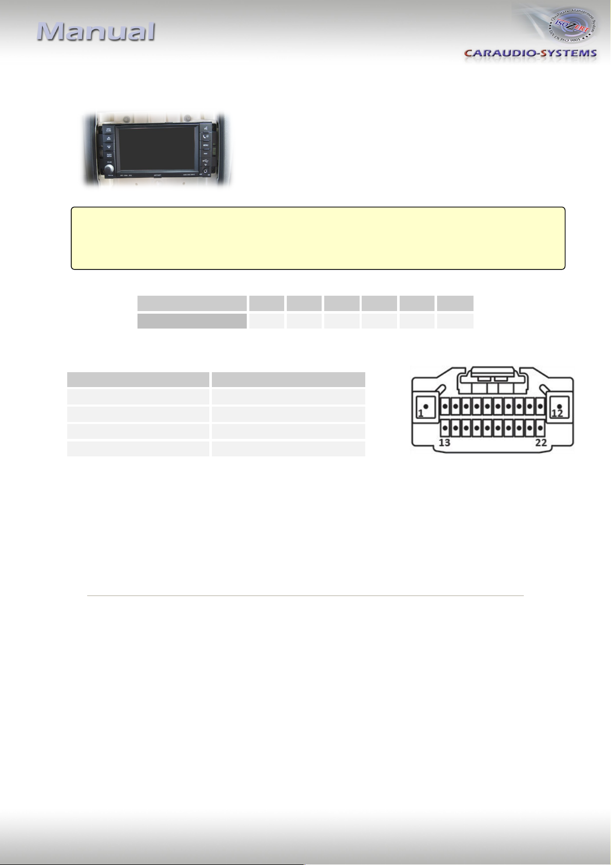
○● White/Orange
CAN-HIGH - Pin 13
○ White
CAN-LOW - Pin 2
● Red
+12V Permanent - Pin 1
●● Black/Green
Ground - Pin 12
Compatible vehicles Chrysler, Dodge and Jeep
Navigation MYGIG RER/REW/REN/REP/RHW
Vehicles with MYGIG
Place of installation is at the back side of the
navigation unit.
No liability for vehicle wire colors and pin definition! Possible changes by the vehicle
manufacturer. The given information must be verified by the installer.
The video-in-motion function is activated permanently without disturbing the navigation
performance.
Version 21.08.2020 TF-U500
Page 12

Page
11
"
Vehicle/ navigation
Dip 1
Dip 2
Dip 3
Dip 4
Dip 5
Dip 6
All vehicles
ON
OFF
OFF
OFF
OFF
OFF
Pin No.
Assignment
Pin 7
CAN-HIGH
Pin 18
CAN-LOW
Pin 12
+12V Permanent
Pin 1
Ground
Pin No.
Assignment
Pin 2
CAN-HIGH
Pin 52
CAN-LOW
Pin 44
+12V Permanent
Pin 43
Ground
Compatible vehicles Chrysler, Dodge, Jeep, Fiat Freemount
Navigation Uconnect with 8.4” monitor with 22pin or 52pin connector on rear of
head-unit
Chrysler, Dodge, Jeep and Fiat Freemount with Uconnnect
Place of installation is at the back side of the
navigation unit.
Vehicles with 22pin connector on rear of head-unit
Vehicles with 52pin connector on rear of head-unit
No liability for vehicle wire colors and pin definition! Possible changes by the vehicle
manufacturer. The given information must be verified by the installer.
The video-in-motion function is activated permanently without disturbing the navigation
performance.
Version 21.08.2020 TF-U500
Page 13

Page
12
"
Vehicle/ navigation
Dip 1
Dip 2
Dip 3
Dip 4
Dip 5
Dip 6
All vehicles
OFF
OFF
OFF
OFF
OFF
OFF
Cable colour
Assignment
● White
CAN HIGH Pin 10
● Grey
CAN LOW Pin 13
Compatible vehicles Citroen, Peugeot
Navigation RT3-N3 CAN, RT4
Vehicles with RT3-N3 CAN and RT4
Place of installation is at the back side of the
navigation unit.
No liability for vehicle wire colors and pin definition!
Possible changes by the vehicle manufacturer. The given
information must be verified by the installer.
Longpress the “SRC”-button on the steering wheel (about 3 seconds) to activate/deactivate
the video-in-motion function. When ignition is off, the video-in-motion interface will be
automatically disabled.
Note: While the video-in-motion function is activated, the navigation performance is not
possible!
Version 21.08.2020 TF-U500
Page 14

Page
13
"
Vehicle/ navigation
Dip 1
Dip 2
Dip 3
Dip 4
Dip 5
Dip 6
All vehicles
ON
OFF
OFF
OFF
OFF
OFF
Cable colour
Assignment
● White
CAN HIGH Pin 10
● Grey
CAN LOW Pin 13
Compatible vehicles Citroen, Peugeot
Navigation NG4 NaviDrive (Citroen), NG4 WipCom/WipNav (Peugeot)
Vehicles with NG4 NaviDrive and NG4 WipCom
Place of installation is at the back side of the
navigation unit.
No liability for vehicle wire colors and pin definition!
Possible changes by the vehicle manufacturer. The given
information must be verified by the installer.
The video-in-motion function is activated permanently without disturbing the navigation
performance.
Note: On some vehicles the navigation performance is affected and as long as the video-in-
motion function is activated the navigation will not be working! In this case you have to
connect the green cable as described in chapter “Exception: Vehicles with RT3-N3 CAN and
RT 4 without Source-button” and set Dip 1 to OFF.
Version 21.08.2020 TF-U500
Page 15

Page
14
"
Vehicle/ navigation
Dip 1
Dip 2
Dip 3
Dip 4
Dip 5
Dip 6
All vehicles
ON
OFF
OFF
OFF
OFF
OFF
Cable colour
Assignment
○● White/Orange
CAN-HIGH - Pin 13
○ White
CAN-LOW - Pin 2
● Red
+12V Permanent - Pin 1
●● Black/Green
Ground - Pin 12
Compatible vehicles Ferrari California
Navigation MYGIG
Ferrari California with MYGIG
Place of installation is at the back side of the
navigation unit.
No liability for vehicle wire colors and pin definition! Possible changes by the vehicle
manufacturer. The given information must be verified by the installer.
The video-in-motion function is activated permanently without disturbing the navigation
performance.
Version 21.08.2020 TF-U500
Page 16

Page
15
"
Vehicle/ navigation
Dip 1
Dip 2
Dip 3
Dip 4
Dip 5
Dip 6
All vehicles
ON
OFF
OFF
OFF
OFF
OFF
Cable colour
Assignment
●● Grau/Orange
CAN-HIGH
●● Violett/Orange
CAN-LOW
Cable colour
Assignment
o● White/Red
+12V Permanent
●● Black/Blue
Ground
Compatible vehicles Ford Edge, Edge 2011
Navigation MYGIG
Stecker A
Stecker B
Connector A
Connector B
Ford Edge with MYGIG
Place of installation is at the back side of the
navigation unit.
Connector A
Connector B
No liability for vehicle wire colors and pin definition!
Possible changes by the vehicle manufacturer. The given
information must be verified by the installer.
The video-in-motion function is activated permanently without disturbing the navigation
performance.
Version 21.08.2020 TF-U500
Page 17

Page
16
"
Vehicle / navigation
Dip 1
Dip 2
Dip 3
Dip 4
Dip 5
Dip 6
All vehicles
ON
OFF
OFF
OFF
OFF
OFF
20pin connector
Assignment
Pin 13
CAN-HIGH
Pin 3
CAN-LOW
Compatible vehicles Civic, Fit (from model 2015)
Navigation HondaLink Next Generation Systems
1
20
Honda with HondaLink Next Generation Systems
Place of installation is at the back side of the
navigation unit.
No liability for vehicle wire colors and pin definition!
Possible changes by the vehicle manufacturer. The given
information must be verified by the installer.
The video-in-motion function is activated permanently without disturbing the navigation
performance.
Version 21.08.2020 TF-U500
Page 18

Page
17
"
Vehicle/ navigation
Dip 1
Dip 2
Dip 3
Dip 4
Dip 5
Dip 6
All vehicles
ON
OFF
OFF
OFF
OFF
ON
Cable colour
Assignment
●● Yellow/Red
+12V Permanent
● Black
Ground
●● Grey/Orange
CAN-HIGH
●● Purple/Orange
CAN-LOW
Compatible vehicles Jaguar XF
Navigation Touch-screen navigation version 2
Jaguar XF with Touch-screen navigation version 2
Place of installation is at the back side of the
radio module.
Attention: CAN-LOW and CAN-HIGH could be reversed at older
vehicles (e.g. Grey/Orange = CAN-LOW)!
No liability for vehicle wire colors and pin definition!
Possible changes by the vehicle manufacturer. The given
information must be verified by the installer.
The video-in-motion function is activated permanently without disturbing the navigation
performance.
Version 21.08.2020 TF-U500
Page 19

Page
18
"
Vehicle/ navigation
Dip 1
Dip 2
Dip 3
Dip 4
Dip 5
Dip 6
All vehicles
ON
OFF
OFF
OFF
OFF
ON
Cable colour
Assignment
●● Grey/Red (Pin 8)
+12V Dauerplus
● Black (Pin 5)
Masse
●● Grey/Orange (Pin 2)
CAN-HIGH
●● Purple/Orange (Pin 1)
CAN-LOW
Compatible vehicles Jaguar XF X250 (from model 2012), XJ X351 (from model 2011)
Navigation Touch-screen navigation version 3
Jaguar XJ and XF with Touch-screen navigation version 3
Place of installation is at the back side of the
monitor.
No liability for vehicle wire colors and pin definition!
Possible changes by the vehicle manufacturer. The given
information must be verified by the installer.
The video-in-motion function is activated permanently without disturbing the navigation
performance.
Version 21.08.2020 TF-U500
Page 20

Page
19
"
Vehicle/ navigation
Dip 1
Dip 2
Dip 3
Dip 4
Dip 5
Dip 6
All vehicles
ON
OFF
OFF
OFF
ON
ON
Cable colour
Assignment
●● Purple/Green
CAN-HIGH - Pin17
●● Purple/Gray
CAN-LOW - Pin16
● Yellow
+12V Permanent - Pin3
● Black
Ground - Pin1
Compatible vehicles Jaguar F-Pace
Navigation INCONTROL TOUCH PRO (10” monitor)
Jaguar with INCONTROL TOUCH PRO
Place of installation is at the back side of the
navigation unit (trunk, left side).
Note: Dip switch functions of the TV-500
Dip 1 – activation TV-free
Dip 2 – no function
Dip 3 – no function
Dip 4 – no function
Dip 5 – CAN-bus termination resistor on the vehicle side
Dip 6 – CAN-bus termination resistor on the head-unit side
Pin-assignment
No liability for vehicle wire colors and pin definition! Possible changes by the vehicle
manufacturer. The given information must be verified by the installer.
The video-in-motion function is activated permanently without disturbing the navigation
performance.
Version 21.08.2020 TF-U500
Page 21

Page
20
"
Vehicle/ navigation
Dip 1
Dip 2
Dip 3
Dip 4
Dip 5
Dip 6
All vehicles
ON
OFF
OFF
OFF
OFF
OFF
Connector
Assignment
Connector B, Pin 11/12
+12V permanent
Connector B, Pin 23/24
Ground
Connector B, Pin 1
CAN-HIGH
Connector B, Pin 13
CAN-LOW
Connector B, Pin 16
Speedsignal
Compatible vehicles KIA Sorento (from model 2015)
Navigation 8” navigation
KIA with 8“ navigation
Place of installation is at the back side of the
navigation unit.
Note: Dip switch functions of the TV-500
Dip 1 – activation TV-free
Dip 2 – factory rear-view camera existing
Dip 3 – TV icon simulation
Dip 4 – no function
Dip 5 – CAN-bus termination resistor on the vehicle side
Dip 6 – CAN-bus termination resistor on the head-unit side
Connector A Connector B
No liability for vehicle wire colors and pin definition! Possible changes by the vehicle
manufacturer. The given information must be verified by the installer.
For video in motion cut and isolate additionally the analogue speedsignal wire (pin 16,
connector B) (navigation still works over GPS reception).
Optionally, a switch can be installed in the severed speedsignal wire (for the case when GPS
reception is bad or not available).
Version 21.08.2020 TF-U500
Page 22

Page
21
"
Vehicle/ navigation
Dip 1
Dip 2
Dip 3
Dip 4
Dip 5
Dip 6
Vehicles without rear-view camera or
with after-market rear-view camera
ON
OFF
OFF
OFF
ON
ON
Vehicles with factory rear-view camera
ON
ON
OFF
OFF
ON
ON
Compatible vehicles Range Rover (Vogue) L322 (2005-2009), Range Rover Sport L320
(2005-2009), Discovery3 L319 (2004-2009)
Navigation Touch-screen navigation version 1
Land Rover with Touch-screen navigation version 1
Place of installation is at the back side of the
radio module. (a hide-away box which is located
behind the glove box or behind the factory
navigation monitor).
Note: Dip switch functions of the TV-500
Dip 1 – activation TV-free
Dip 2 – factory rear-view camera existing
Dip 3 – TV icon simulation
Dip 4 – no function
Dip 5 – CAN-bus termination resistor on the vehicle side
Dip 6 – CAN-bus termination resistor on the head-unit side
Version 21.08.2020 TF-U500
Page 23

Page
22
"
Cable colour
Assignment
●○ Yellow/White
CAN-HIGH Pin 9
●● Yellow/Blue
CAN-LOW Pin 10
Cable colour
Assignment
●○ Yellow/White
CAN-HIGH
● Yellow
CAN-LOW
Range Rover Vogue
Sport & Discovery
No liability for vehicle wire colors and pin definition! Possible changes by the vehicle
manufacturer. The given information must be verified by the installer.
The video-in-motion function is activated permanently without disturbing the navigation
performance.
Version 21.08.2020 TF-U500
Page 24

Page
23
"
Vehicle/ navigation
Dip 1
Dip 2
Dip 3
Dip 4
Dip 5
Dip 6
Vehicles without rear-view camera
ON
OFF
OFF
OFF
ON
ON
Vehicles with rear-view camera
ON
ON
OFF
OFF
ON
ON
Compatible vehicles Range Rover (Vogue) L322 (2005-2009), Range Rover Sport L320
(2005-2009), Discovery3 L319 (2004-2009)
Navigation Touch-screen navigation version 2
Land Rover with Touch-screen navigation version 2
Place of installation is at the back side of the
radio module. (a hide-away box which is located
behind the glove box or behind the factory
navigation monitor).
Note: Dip switch functions of the TV-500
Dip 1 – activation TV-free
Dip 2 – rear-view camera existing
Dip 3 – TV icon simulation
Dip 4 – no function
Dip 5 – termination resistor CAN-Bus
Dip 6 – termination resistor CAN-Bus
Setting dip 2 to ON codes the factory rear-view camera input which is located on the brown
Fakra male connector of the factory monitor. When reverse gear is engaged, the navigation
will automatically switch to this input. On vehicles with factory rear-view camera set Dip 2 to
ON, too.
Version 21.08.2020 TF-U500
Page 25

Page
24
"
Cable colour
Assignment
●○ Yellow/White
CAN-HIGH Pin 9
●● Yellow/Blue
CAN-LOW Pin 10
Cable colour
Assignment
●○ Yellow/White
CAN-HIGH
● Yellow
CAN-LOW
Range Rover Vogue
Sport & Discovery
No liability for vehicle wire colors and pin definition! Possible changes by the vehicle
manufacturer. The given information must be verified by the installer.
The video-in-motion function is activated permanently without disturbing the navigation
performance.
Version 21.08.2020 TF-U500
Page 26

Page
25
"
Vehicle/ navigation
Dip 1
Dip 2
Dip 3
Dip 4
Dip 5
Dip 6
Vehicles without rear-view camera
ON
OFF
OFF
OFF
ON
ON
Vehicles with rear-view camera
ON
ON
OFF
OFF
ON
ON
Compatible vehicles Range Rover Evoque L538, Range Rover Sport, Discovery4
from year 2012
Navigation Touch-Screen Navigation 3rd generation
Land Rover from 2012 with Touch-screen navigation version 3
Place of installation is at the back side of the
monitor.
Note: Dip switch functions of the TV-500
Dip 1 – activation TV-free
Dip 2 – rear-view camera existing
Dip 3 – TV icon simulation
Dip 4 – no function
Dip 5 – CAN-bus termination resistor on the vehicle side
Dip 6 – CAN-bus termination resistor on the head-unit side
Setting dip 2 to ON codes the factory rear-view camera input which is located on the brown
Fakra male connector of the factory monitor. When reverse gear is engaged, the navigation
will automatically switch to this input. On vehicles with factory rear-view camera set Dip 2 to
ON, too.
Version 21.08.2020 TF-U500
Page 27

Page
26
"
Cable colour
Assignment
●● Orange/grey
CAN-HIGH Pin 2
●● Orange/purple
CAN-LOW Pin 1
Pin-assignment factory monitor connector
No liability for vehicle wire colors and pin definition! Possible changes by the vehicle
manufacturer. The given information must be verified by the installer.
The video-in-motion function is activated permanently without disturbing the navigation
performance.
Version 21.08.2020 TF-U500
Page 28

Page
27
"
Vehicle/ navigation
Dip 1
Dip 2
Dip 3
Dip 4
Dip 5
Dip 6
Vehicles without rear-view camera
ON
OFF
OFF
OFF
ON
ON
Vehicles with rear-view camera
ON
ON
OFF
OFF
ON
ON
Compatible vehicles Land Rover vehicles from year 2015
Navigation Touch-Screen Navigation 4th generation (8” monitor)
Land Rover from 2015 with Touch-screen navigation version 4
Place of installation is at the back side of the
navigation unit.
Note: Dip switch functions of the TV-500
Dip 1 – activation TV-free
Dip 2 – rear-view camera existing
Dip 3 – TV icon simulation
Dip 4 – no function
Dip 5 – CAN-bus termination resistor on the vehicle side
Dip 6 – CAN-bus termination resistor on the head-unit side
Setting dip 2 to ON codes the factory rear-view camera input which is located on the brown
Fakra male connector of the factory monitor. When reverse gear is engaged, the navigation
will automatically switch to this input. On vehicles with factory rear-view camera set Dip 2 to
ON, too.
Version 21.08.2020 TF-U500
Page 29

Page
28
"
Function
Pin-No.
CAN-HIGH
Pin 3 (chamber B)
CAN-LOW
Pin 9 (chamber B)
+12V permanent
Pin 13
Ground
Pin 11
Pin-assignment Quadlock connector
No liability for vehicle wire colors and pin definition! Possible changes by the vehicle
manufacturer. The given information must be verified by the installer.
The video-in-motion function is activated permanently without disturbing the navigation
performance.
Version 21.08.2020 TF-U500
Page 30

Page
29
"
Vehicle/ navigation
Dip 1
Dip 2
Dip 3
Dip 4
Dip 5
Dip 6
All vehicles
ON
OFF
OFF
OFF
ON
ON
Cable colour
Assignment
●● Purple/Green
CAN-HIGH - Pin17
●● Purple/Gray
CAN-LOW - Pin16
● Yellow
+12V Permanent - Pin3
● Black
Ground - Pin1
Compatible vehicles Range Rover Evoque, Sport from year 2016
Navigation INCONTROL TOUCH PRO (10” monitor)
Land Rover with INCONTROL TOUCH PRO
Place of installation is at the back side of the
navigation unit (below passenger seat).
Note: Dip switch functions of the TV-500
Dip 1 – activation TV-free
Dip 2 – no function
Dip 3 – no function
Dip 4 – no function
Dip 5 – CAN-bus termination resistor on the vehicle side
Dip 6 – CAN-bus termination resistor on the head-unit side
Pin-assignment
No liability for vehicle wire colors and pin definition! Possible changes by the vehicle
manufacturer. The given information must be verified by the installer.
The video-in-motion function is activated permanently without disturbing the navigation
performance.
Version 21.08.2020 TF-U500
Page 31

Page
30
"
Vehicle/ navigation
Dip 1
Dip 2
Dip 3
Dip 4
Dip 5
Dip 6
All vehicles
ON
OFF
OFF
OFF
OFF
OFF
Cable colour
Assignment
● Red
+12V Permanent A Pin 4
● Black
Ground A Pin 8
●● Brown/Red
CAN-HIGH C2 Pin 9
● Brown
CAN-LOW C2 Pin 8
Compatible vehicles Mercedes Benz C-class (W203) til 03/2004, CLK-class (C208 W208) all
years, CLK-class (C209 W209) til 05/2004, E-class (W210) all years, GModel (G463) from 12/2000 til 03/2007, ML-class (W163) all years, SLclass (R230) til 06/2004, CL-class (C215) til 09/2003, S-class (W220) til
09/2003
Navigation Comand 2.0, Comand APS220/CD
Mercedes Benz with Comand 2.0
Place of installation is at the back side of the
navigation unit.
No liability for vehicle wire colors and pin definition!
Possible changes by the vehicle manufacturer. The given
information must be verified by the installer
The video-in-motion function is activated permanently without disturbing the navigation
performance.
Version 21.08.2020 TF-U500
Page 32

Page
31
"
Vehicle/ navigation
Dip 1
Dip 2
Dip 3
Dip 4
Dip 5
Dip 6
All vehicles
ON
OFF
OFF
OFF
OFF
OFF
Cable colour
Assignment
● Red
+12V Permanent A Pin 4
● Black
Ground A Pin 8
●● Brown/Red
CAN-HIGH C2 Pin 18
● Brown
CAN-LOW C2 Pin 17
Compatible vehicles Mercedes Benz CL-class (C215) til 09/2003, S-class (W220) til 09/2003
Navigation Comand 2.5
Mercedes Benz with Comand 2.5
Place of installation is at the back side of the
navigation unit.
No liability for vehicle wire colors and pin definition!
Possible changes by the vehicle manufacturer. The given
information must be verified by the installer
The video-in-motion function is activated permanently without disturbing the navigation
performance.
Version 21.08.2020 TF-U500
Page 33

Page
32
"
Vehicle/ navigation
Dip 1
Dip 2
Dip 3
Dip 4
Dip 5
Dip 6
All vehicles
ON
OFF
OFF
OFF
OFF
OFF
Cable colour
Assignment
●● Brown/Red
CAN-HIGH Pin 2
● Brown
CAN-LOW Pin 4
Compatible vehicles Maybach (with green Fakra connector on backside of Comand),
Mercedes Benz CL-class (C215) from 10/2003 til 12/2005, S-class
(W220) from 10/2003 til 09/2005, SL-class (R230) from 07/2004 til
03/2008, CLS-Coupe (W219) from 10/2004 til 03/2008, E-class (W211)
til 05/2008, SLK-class (R171) from 03/2004 til 03/2008
Navigation Comand APS DVD, Comand APS NTG1
Maybach and Mercedes Benz with Comand APS NTG 1
Place of installation is at the AGW-module (Audio-Gate Way). The AGW-module is placed in the luggage
compartment at the left hand side behind the cover of
the navigation unit or under the driver seat (SLK R171)
or under the front passenger seat (SL R230).
No liability for vehicle wire colors and pin definition!
Possible changes by the vehicle manufacturer. The given
information must be verified by the installer.
The video-in-motion function is activated permanently without disturbing the navigation
performance.
Version 21.08.2020 TF-U500
Page 34

Page
33
"
Vehicle/ navigation
Dip 1
Dip 2
Dip 3
Dip 4
Dip 5
Dip 6
Vehicles with NTG2/NTG4-xxx
ON
OFF
OFF
OFF
OFF
OFF
Vehicles with NTG2.5/NTG4.5
OFF
OFF
OFF
OFF
OFF
OFF
Compatible vehicles Mercedes Benz A-class (W169) from 09/2004 til 06/2008,
B-class (W245) from 09/2004 til 06/2008, C-class (W203)
from 04/2004 til 02/2007, CLC-class (CL203) from 06/2008 til
09/2008, CLK-class (C209 W209) from 06/2004, G-model
(G463) from 04/2007 til 08/2008, GL-class (X164) til 06/2008,
ML-class (W164) til 06/2008, R-class (W251) til 06/2008,
Sprinter, Viano, A-class (W169) from 07/2008, B-class (W245)
from 07/2008 til 10/2011, CLS-Coupe (W219) from 04/2008 til
12/2010, E-class (W211) from 06/2008 til 03/2009, G-model
(G463) from 09/2008, GL-class (X164) from 07/2008, ML-class
(W164) from 07/2008 til 10/2011, R-class (W251) from
07/2008, SL-class (R230) from 04/2008, SLK-class (R171) from
04/2008 til 02/2011, Viano, C-class (W204) from 03/2007 til
02/2011, CLC-class (CL203) from 09/2008, GLK-class (X204)
from 09/2008, SLS (C197) from 03/2010, E-class (W212) from
04/2009 til 05/2011, E-class Coupe (W207) from 05/2009 til
05/2011, CLS-Coupe (C218) from 01/2011 til 05/2011, B-class
(W246) from 11/2011, C-class (W204) from 03/2011, C-class
Coupe (C204) from 06/2011, E-class (W212) from 06/2011, Eclass Coupe (C207) from 06/2011, CLS-Coupe (C218) from
06/2011, GLK-class (W204) from 01/2011, ML-class (W166)
from 11/2011, SLK-class (R172) from 03/2011, SL-class (R231)
from 2012, VW Crafter
Navigation Comand APS NTG2/NTG2.5/NTG4-204/NTG4-212,
Comand Online NTG 4.5
Mercedes Benz with Comand APS NTG 2/NTG 2.5/NTG 4 and Comand Online, NTG 4.5
VW Crafter with Comand APS NTG2
Place of installation is at the back side of the
navigation unit.
Version 21.08.2020 TF-U500
Page 35

Page
34
"
Cable colour
Assignment
●● Red/Blue
+12Volt Permanent 15
● Brown
Ground Pin 12
●● Brown/Red
CAN HIGH Pin 11
● Brown
CAN LOW Pin 9
No liability for vehicle wire colors and pin definition!
Possible changes by the vehicle manufacturer. The given
information must be verified by the installer.
On vehicles with NTG2/NTG4-2xx the video-in-motion function is activated permanently
without disturbing the navigation performance.
On vehicles with NTG2.5/NTG4.5 select the “navigation level” on the
instrument and press the “hang-up”-button on the steering-wheel for
more than 3 seconds to activate/deactivate the video-in-motion
function. When the ignition is off, the video-in-motion interface will be
automatically disabled.
Note: As long as the video-in-motion function is activated, the navigation
of the command will NOT be working!
Version 21.08.2020 TF-U500
Page 36

Page
35
"
Vehicle/ navigation
Dip 1
Dip 2
Dip 3
Dip 4
Dip 5
Dip 6
All vehicles
ON
OFF
OFF
OFF
ON
ON
Cable colour
Assignment
●o Yellow/White
CAN-HIGH Pin 1
● Yellow
CAN-LOW Pin 11
Compatible vehicles Mercedes Benz CL-class (C216) from 01/2006 til 05/2009,
S-class (W221) from 10/2005 til 05/2009, S-class (W221) from
06/2009, CL-class (C216) from 06/2009 with Dual-View
Navigation Comand APS NTG 3 and NTG 3.5
Vehicles with Mercedes Benz Comand NTG 3 and NTG 3.5
Place of installation is in the centre console
behind the DVD unit.
No liability for vehicle wire colors and pin definition! Possible changes by the vehicle
manufacturer. The given information must be verified by the installer.
The video-in-motion function is activated permanently without disturbing the navigation
performance.
Version 21.08.2020 TF-U500
Page 37

Page
36
"
Vehicle/ navigation
Dip 1
Dip 2
Dip 3
Dip 4
Dip 5
Dip 6
Video-in-motion permanent
ON
OFF
OFF
OFF
OFF
ON
Video-in-motion selective*
OFF
OFF
OFF
OFF
OFF
ON
Cable colour
Assignment
● Red
+12Volt Permanent 15
● Brown
Ground Pin 12
●● Yellow/White ; ●● Brown/Red ;
●● Purple/White
CAN HIGH Chamber B -Pin 9
● Yellow ; ● Brown ;
● Purple
CAN LOW Chamber B - Pin 3
Requirements
Vehicle Mercedes Benz C-class (W205), S-class (W222), V-class (W477)
and more types.
Navigation Comand NTG 5, Comand NTG5.1
Vehicles with Mercedes Benz Comand NTG 5 / NTG5.1
Place of installation is at the back side of the
navigation unit.
Pin-assignment vehicle connector
No liability for vehicle wire colors and pin definition! Possible changes by the vehicle
manufacturer. The given information must be verified by the installer.
The video-in-motion function is activated permanently without disturbing the navigation
performance.
Version 21.08.2020 TF-U500
Page 38

Page
37
"
Vehicle/ navigation
Dip 1
Dip 2
Dip 3
Dip 4
Dip 5
Dip 6
Video-in-motion permanent
ON
OFF
OFF
OFF
OFF
ON
Video-in-motion selective*
OFF
OFF
OFF
OFF
OFF
ON
Cable colour
Assignment
● Red
+12Volt Permanent - Pin14
● Brown
Ground - Pin 1
●● Purple/White
CAN HIGH - Pin 7
● Purple
CAN LOW - Pin 20
Requirements
Vehicle Mercedes Benz A-class (W177), Sprinter (W907), GLE (C167),
GLS (X167) und more types.
Navigation MBUX NTG 6
Limitations
MBUX Augmented Reality While the video-in-motion function is active, it is not possible to
use the camera traffic light display function!
Vehicles with Mercedes Benz MBUX NTG 6
Place of installation is at the back side of the
navigation unit.
A-class: On the A-pillar on the driver's side
GLE, GLS: Below passenger seat
Sprinter: Behind the factory monitor
Video-in-motion selective via hang up button
With Dip 1 set to OFF, a long press (3 sec.) on the steering wheel
"hang up" button is used to activate / deactivate the video-in-motion
function.
(After ACC is switched off, the video-in-motion function will be
automatically deactivated)
Pin-assignment vehicle connector – 26pin version
No liability for vehicle wire colors and pin definition! Possible changes by the vehicle
manufacturer. The given information must be verified by the installer.
The video-in-motion function is activated permanently without disturbing the navigation
performance.
Version 21.08.2020 TF-U500
Page 39

Page
38
"
Vehicle/ navigation
Dip 1
Dip 2
Dip 3
Dip 4
Dip 5
Dip 6
All vehicles
ON
OFF
OFF
OFF
OFF
OFF
Cable colour
Assignment
● Red
+12V Dauerstrom Pin 4
● Black
Ground Pin 8
●● Orange/Purple
CAN HIGH Pin 1 (Kammer C1)
●● Orange/Brown
CAN LOW Pin 2 (Kammer C1)
Compatible vehicles Porsche Cayenne E1
Navigation PCM 2.1
Porsche with PCM 2.1
Place of installation is at the back side of the
navigation unit.
No liability for vehicle wire colors and pin definition!
Possible changes by the vehicle manufacturer. The given
information must be verified by the installer.
The video-in-motion function is activated permanently without disturbing the navigation
performance.
Version 21.08.2020 TF-U500
Page 40

Page
39
"
Vehicle/ navigation
Dip 1
Dip 2
Dip 3
Dip 4
Dip 5
Dip 6
Vehicles without rear-view camera or
with after-market rear-view camera
ON
OFF
OFF
OFF
ON
ON
Vehicles with factory rear-view camera
ON
ON
OFF
OFF
ON
ON
Cable colour
Assignment
● Red
+12V Permanent Pin 15
● Black
Ground Pin 12
●● Orange/Purple
CAN HIGH Pin 11
●● Orange/Brown
CAN LOW Pin 9
Compatible vehicles Cayenne E1, 911, Boxster, Cayman, Cayenne E2, Panamera
Navigation PCM 3.0 and 3.1
Limitations
Internal DVD video cannot be watched!
Porsche with PCM 3.0 and PCM 3.1
Place of installation is at the back side of the
navigation unit.
No liability for vehicle wire colors and pin definition!
Possible changes by the vehicle manufacturer. The given
information must be verified by the installer.
The video-in-motion function is activated permanently without disturbing the navigation
performance.
Version 21.08.2020 TF-U500
Page 41

Page
40
"
Vehicle/navigation
Dip 1
Dip 2
Dip 3
Dip 4
Dip 5
Dip 6
PCM4
ON
OFF
OFF
OFF
OFF
OFF
Cable colour
Assignment
● Red
+12V permanent Pin 18
● Black
Ground Pin 17
●● Orange/Purple
CAN HIGH Pin 6
●● Orange/Brown
CAN LOW Pin 12
Compatible vehicles 911
Navigation PCM4
Porsche with PCM4
Place of installation is at the back side of the navigation unit
No liability for vehicle wire colors and pin definition!
Possible changes by the vehicle manufacturer. The given
information must be verified by the installer.
The video-in-motion function is activated permanently without disturbing the navigation
performance.
Version 21.08.2020 TF-U500
Page 42

Page
41
"
Vehicle/navigation
Dip 1
Dip 2
Dip 3
Dip 4
Dip 5
Dip 6
R-Link
ON
OFF
OFF
OFF
ON
ON
Cable colour
Assignment
● Purple / ●● Grey-white
CAN HIGH Pin 12
● White / ●● Brown-white
CAN LOW Pin 11
Compatible vehicles Captur, Megane III, ZOE, Fortwo, Forfour
Navigation R-Link 1, Smart Media-System (7“)
Renault / Smart
Place of installation is at the back side of the monitor.
No liability for vehicle wire colors and pin definition!
Possible changes by the vehicle manufacturer. The given
information must be verified by the installer.
The video-in-motion function is activated permanently without disturbing the navigation
performance.
Version 21.08.2020 TF-U500
Page 43

Page
42
"
Fahrzeug/ Navigation
Dip 1 Dip 2 Dip 3 Dip 4 Dip 5 Dip
6
Vehicles WITHOUT extra equipment (lane pilot,
distance assistant, city safety system)
ON
OFF
OFF
OFF
ON
ON
Vehicles WITH extra equipment (lane pilot, distance
assistant, city safety system)
OFF
OFF
OFF
OFF
ON
ON
Cable colour
Assignment
●● Purple/Red
+12V Permanent
●● Black/Grey
Ground
●● Grey/Orange
CAN HIGH Pin 10
●● Purple/Orange
CAN LOW Pin 09
Compatible vehicles Volvo S-series, V-series, XC60
Navigation RTI 2011
Limitations
Vehicles with lane pilot, The included green cable is used to activate the video-in-motion
distance assistant and function (+12V = activated).
city safety system
Lane pilot, distance assistant and city safety system do not work while TV-free is activated!
Volvo with RTI 2011
Place of installation is at the back side of the
monitor.
No liability for vehicle wire colors and pin definition!
Possible changes by the vehicle manufacturer. The given
information must be verified by the installer.
Version 21.08.2020 TF-U500
Page 44

Page
43
"
On vehicles without extra equipment and Dip1 to ON the video-in-motion function is
activated permanently without disturbing the navigation performance.
On vehicles with extra equipment and Dip1 to OFF the included green cable is used to
activate the video-in-motion function.
Connect a switch to the green cable and connect the green cable to +12V ACC.
● +12V = TV-Free is activated
● 0V = TV-Free is not activated
Note: As long as the video-in-motion function is activated, the navigation will NOT be
working!
Version 21.08.2020 TF-U500
Page 45

Page
44
"
Vehicle/ navigation
Dip 1
Dip 2
Dip 3
Dip 4
Dip 5
Dip 6
All vehicles
ON
OFF
OFF
OFF
OFF
OFF
Cable colour
Assignment
●● Red/Yellow
+12V Permanent Pin 15
● Brown
Ground Pin 12
●● Orange/Green
CAN HIGH Pin 9
●● Orange/Brau
CAN LOW Pin 10
Compatible vehicles VW Touareg; Golf 5, Touran, T5, Passat from year 2006, Caddy Live,
Skoda Octavia 2 and other vehicles
Navigation VW MFD2/RNS2, Skoda Nexus
Vehicles with VW MFD2/RNS2 und Skoda Nexus
Place of installation is at the back side of the
navigation unit.
No liability for vehicle wire colors and pin definition!
Possible changes by the vehicle manufacturer. The given
information must be verified by the installer.
The video-in-motion function is activated permanently without disturbing the navigation
performance.
Version 21.08.2020 TF-U500
Page 46

Page
45
"
Vehicle/ navigation
Dip 1
Dip 2
Dip 3
Dip 4
Dip 5
Dip 6
All vehicles
ON
OFF
OFF
OFF
OFF
OFF
Cable colour
Assignment
●● Red/Yellow
+12V Permanent Pin 15
● Brown
Ground Pin 12
●● Orange/Green
CAN HIGH Pin 9
●● Orange/Brau
CAN LOW Pin 10
Compatible vehicles VW Touareg, T5, Touran, Golf 6 and other vehicles
Navigation VW RNS510 and 810, Skoda Columbus, Seat Trinax
Vehicles with VW RNS510/810, Skoda Columbus and Seat Trinax
Place of installation is at the back side of the navigation unit.
No liability for vehicle wire colors and pin definition!
Possible changes by the vehicle manufacturer. The given
information must be verified by the installer.
The video-in-motion function is activated permanently without disturbing the navigation
performance.
Version 21.08.2020 TF-U500
Page 47

Page
46
"
Vehicle/navigation
Dip 1
Dip 2
Dip 3
Dip 4
Dip 5
Dip 6
MIB High
ON
OFF
OFF
OFF
ON
ON
Cable colour
Assignment
● Red
+12V permanent Pin 18
● Brown
Ground Pin 17
●● Orange/Violet
CAN HIGH Pin 6
●● Orange/Brown
CAN LOW Pin 12
Compatible vehicles Golf 7, Octavia 3
Navigation MIB High – Discover Pro, Columbus
Vehicles with VW, Skoda MIB High
Place of installation is at the back side of the navigation unit
No liability for vehicle wire colors and pin definition!
Possible changes by the vehicle manufacturer. The given
information must be verified by the installer.
The video-in-motion function is activated permanently without disturbing the navigation
performance.
Version 21.08.2020 TF-U500
Page 48

Page
47
"
3. Specifications
Operation voltage 10.5 – 14.8V
Stand-by power drain <2mA
Operation power drain ~60mA
Power consumption ~0,08W
Temperature range -30°C to +80°C
Weight 44g
Measurements (box only) W x H x D 76 x 27 x 54 mm
4. Technical support
Caraudio-Systems Vertriebs GmbH
manufacturer/distribution
In den Fuchslöchern 3
D-67240 Bobenheim-Roxheim
email support@caraudio-systems.de
Legal disclaimer: Mentioned company and trademarks, as well as product names/codes are registered
trademarks ® of their corresponding legal owners.
Version 21.08.2020 TF-U500
 Loading...