

Page 1
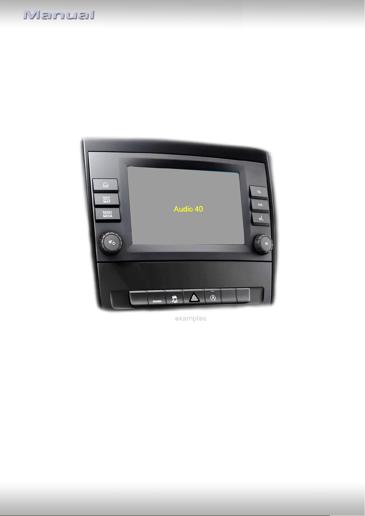
Video-inserter
RL4-A40
Compatible with
Mercedes Benz vehicles with
Garmin Audio30 or Audio40 infotainment
Video-inserter for front- and rear-view camera
and two additional video sources
Product features
Video-inserter for factory-infotainment systems
1 CVBS Input for rear-view camera
1 CVBS Input for front camera
2 CVBS video-inputs for after-market devices (e.g. USB-Player, DVB-T2 tuner)
Automatic switching to rear-view camera input on engagement of the reverse gear
Automatic front camera switching after reverse gear for 10 seconds
Video-in-motion (ONLY for connected video-sources)
Video-inputs NTSC compatible
Version 10.02.2023 HW CAM(V100) / (V20.3) RL4-A40
Page 2
Pag
e2
Contents
1. Prior to installation
1.1. Delivery contents
1.2. Checking the interface compatibility of vehicle and accessories
1.3. Connectors - video interface
1.4. Connectors - daughter PCB
1.5. Dip-switch settings
1.5.1. 8 dip – black
1.5.1.1. Activating the front camera input (dip 1)
1.5.1.2. Enabling the interface’s video inputs (dip 2-3)
1.5.1.3. Rear-view camera setting (dip 5)
1.5.2. 4 dip - red
2. Installation
2.1. Place of installation
2.2. Connection scheme
2.3. Installation – Daughter PCB
2.3.1. Warning notes, concerning the installation of ribbon cables
2.4. Connection – 20pin picture signal cable
2.5. Connection – 10pin Power / CAN cable
2.6. Analogue power supply
2.7. Power supply output
2.8. Connection – video inputs
2.8.1. Audio insertion
2.8.2. After-market front camera
2.8.3. After-market rear-view camera
2.8.3.1. Case 1: Interface receives the reverse gear signal
2.8.3.2. Case 2: Interface does not receive the reverse gear signal
2.9. Connection – external keypad
3. Interface operation by external keypad
4. Picture settings
5. Specifications
6. Frequently asked questions
7. Technical support
Version 10.02.2023 HW CAM(V100) / (V20.3) RL4-A40
Page 3
Pag
e3
Legal Information
By law, watching moving pictures while driving is prohibited, the driver must not be
distracted. We do not accept any liability for material damage or personal injury resulting,
directly or indirectly, from installation or operation of this product. This product should only
be used while standing or to display fixed menus or rear-view-camera video when the
vehicle is moving, for example the MP3 menu for DVD upgrades.
Changes/updates of the vehicle’s software can cause malfunctions of the interface. We
offer free software-updates for our interfaces for one year after purchase. To receive a free
update, the interface must be sent in at own cost. Labour cost for and other expenses
involved with the software-updates will not be refunded.
1. Prior to installation
Read the manual prior to installation.
Technical knowledge is necessary for installation. The place of installation has to be free of
moisture and away from heat sources.
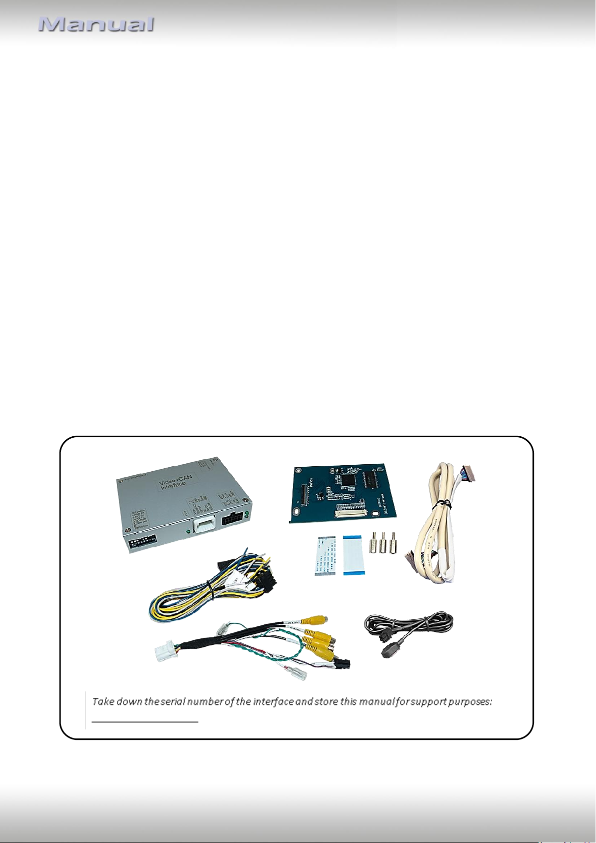
1.1. Delivery contents
Version 10.02.2023 HW CAM(V100) / (V20.3) RL4-A40
Page 4
Pag
e4
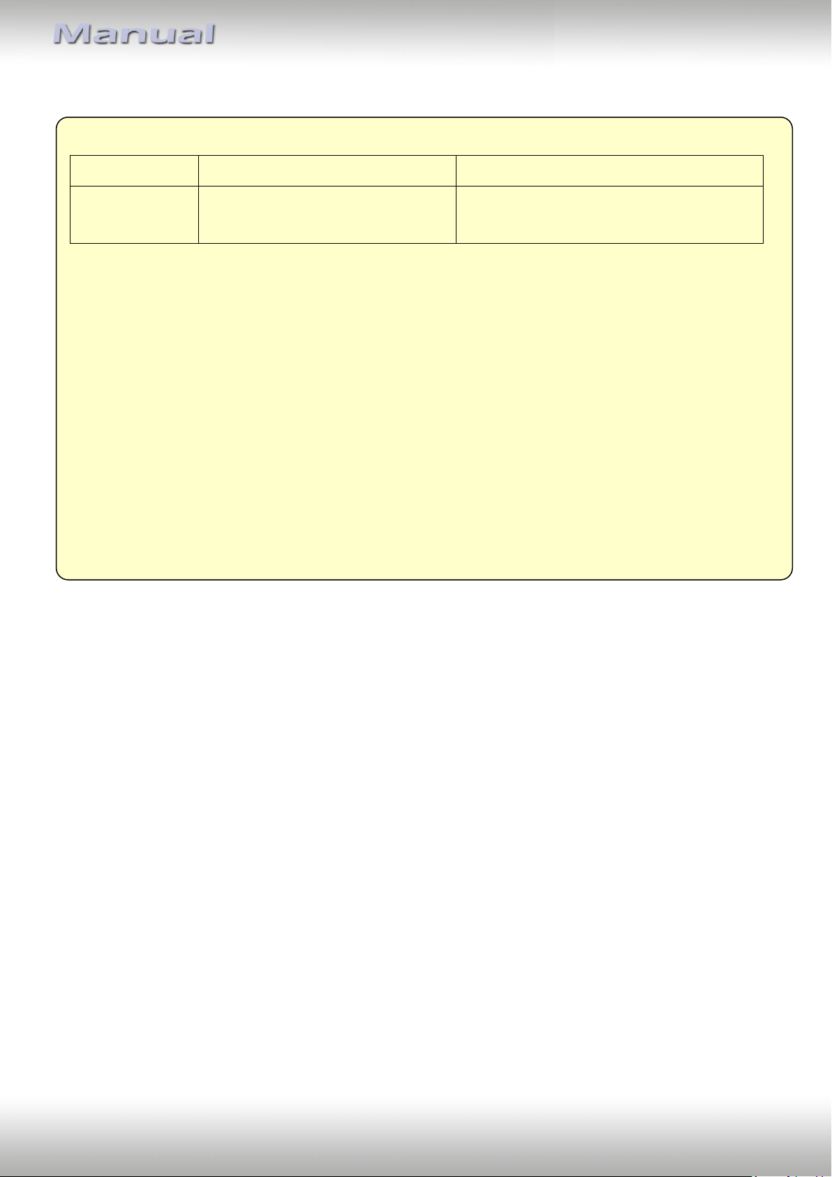
Requirements
Brand
Compatible vehicles
Compatible systems
Mercedes-Benz
Vito (W447) since about 2019
Garmin Audio30/Audio40
Only for head-units made by Garmin - not
compatbile with Audio40 made by Pioneer
Limitations
Video only The interface inserts ONLY video signals into the infotainment.
For inserting Audio signals either the possibly existing factory audio-AUX-input or
a FM-modulator can be used.
In case that 2 AV sources shall be connected, a desired audio switching will
require additional electronic.
Factory rear-view camera Automatically switching-back from inserted video to factory rear-view camera is
only possible while the reverse gear is engaged. To delay the switch-back an
additional electronic part is required.
After market front camera The front camera will automatically be switched for 10 seconds after disengaging
the reverse gear. A manually front camera switching is possible by external
keypad.
Video input signal NTSC video sources compatible only.
1.2. Checking the compatibility of vehicle and accessories
Version 10.02.2023 HW CAM(V100) / (V20.3) RL4-A40
Page 5
Pag
e5
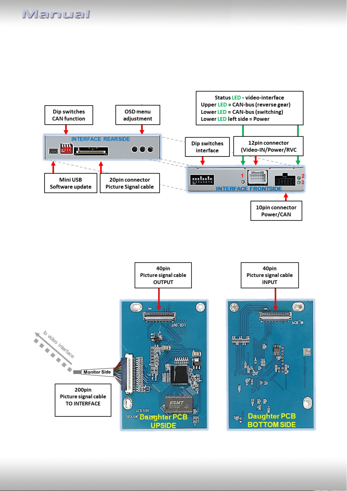
1.3. connectors - video-interface
The video-interface (daughter PCB) converts the video signals of connected after-market
sources in a factory monitor compatible picture signal which is inserted in the factory
monitor, by using separate trigger options.
1.4. connectors – daughter PCB
Version 10.02.2023 HW CAM(V100) / (V20.3) RL4-A40
Page 6
Pag
e6
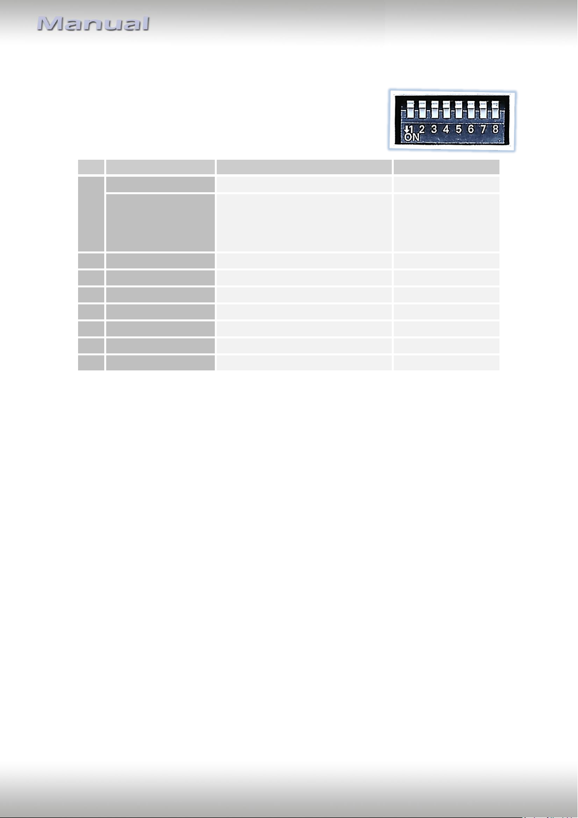
Dip
Function
ON (down)
OFF (up)
1
Front camera
enabled*
disabled
Power supply
output
(red wire)
+12V (max. 3A) when reverse gear
is engaged incl. 10 seconds delay
and +12V by manual switching to
front camera by keypad
+12V (max. 3A) ACC
2
CVBS AV1-input
enabled
disabled
3
CVBS AV2-input
enabled
disabled
4
No function
Set to OFF
5
Rear-view cam type
after-market
factory or none
6
No function
Set to OFF
7
No function
Set to OFF
8
No function
Set to OFF
1.5. Dip-switch settings
1.5.1. 8 dip - black
Some settings have to be selected by the dip-switches on the
video interface.
Dip position down is ON and position up is OFF.
*The front camera will automatically be switched for 10 seconds after disengaging the
reverse gear (see following information).
After each Dip-switch-change a power-reset of the Video Interface has to be performed!
1.5.1.1. Activating the front camera input (dip 1)
If set to ON, the interface switches for 10 seconds from the rear-view camera to the front
camera input after having disengaged the reverse gear. In addition, a manual switch-over to
the front camera input is possible via keypad (short press) from any image mode.
Description of the front camera power supply: see chapter “Power supply output”.
1.5.1.2. Enabling the interface’s video inputs (dip 2-3)
Only the enabled video inputs can be accessed when switching through the interface’s video
sources. It is recommended to enable only the required inputs, disabled inputs
will be skipped when switching through the video-interfaces inputs.
Version 10.02.2023 HW CAM(V100) / (V20.3) RL4-A40
Page 7
Pag
e7
Vehicle/Navigation
Dip 1
Dip 2
Dip 3
Dip 4
All vehicles
OFF
OFF
OFF
OFF
1.5.1.3. Rear-view camera setting (dip 5)
If set to OFF, the interface switches to factory picture while the reverse gear is engaged to
display factory rear-view camera.
If set to ON, the interface switches to its rear-view camera input „V4 Reverse“ while the
reverse gear is engaged.
Note: Dip 4, 6, 7 and 8 are out of function and have to be set to OFF.
After each Dip-switch-change a power-reset of the Video Interface has to be performed!
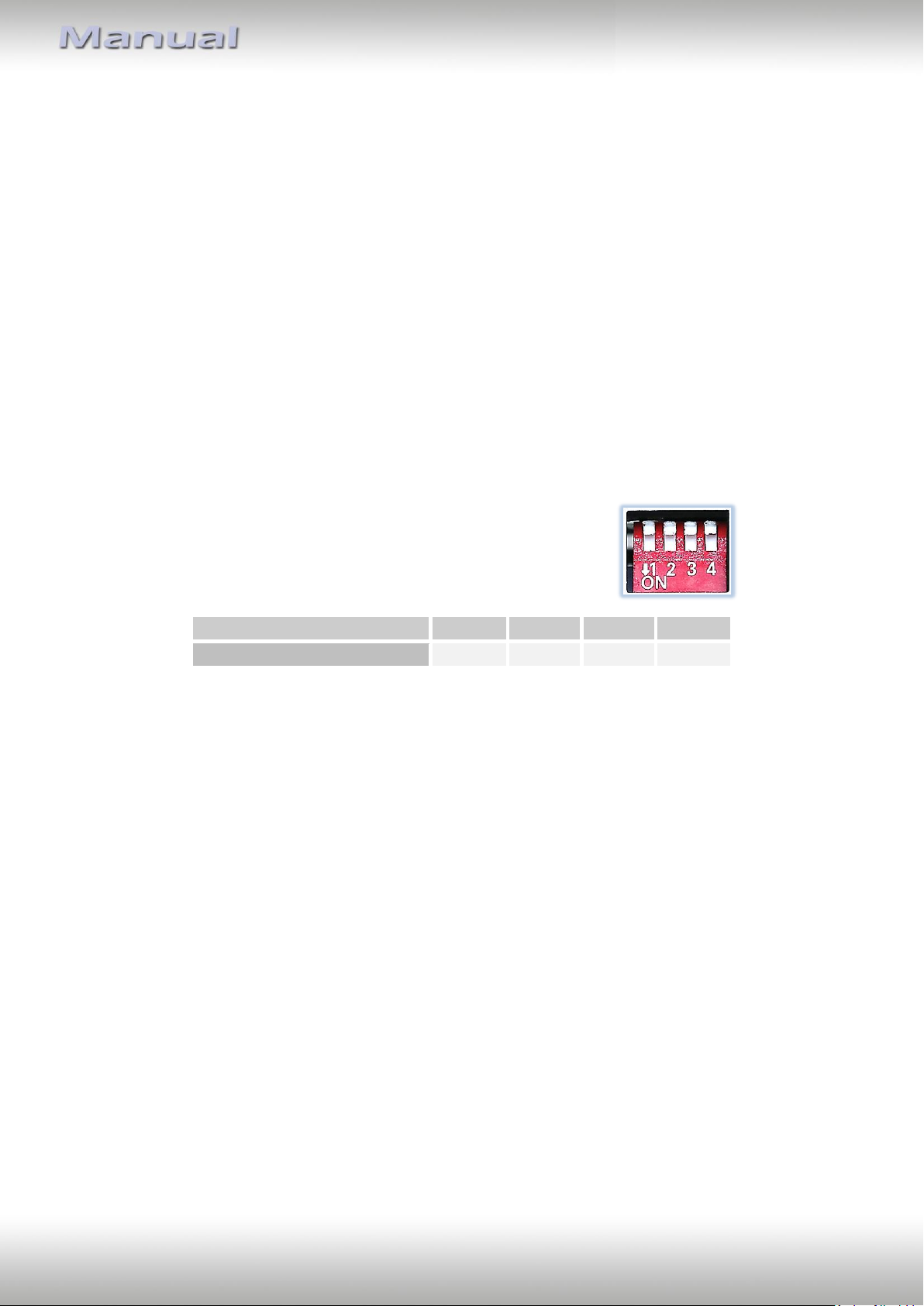
1.5.2. 4 dip - red
By using the Dip-switches, the factory Head-unit or vehicle can be chosen which the
interface will be connected to.
Dip position down is ON and position up is OFF.
Set all dip switches to off
Version 10.02.2023 HW CAM(V100) / (V20.3) RL4-A40
Page 8
Pag
e8
2. Installation
To install the interface, first switch off the ignition and disconnect the vehicle’s battery.
Please read the owner`s manual of the car, regarding the battery`s disconnection! If
required, enable the car`s Sleep-mode (hibernation mode)
In case the sleep-mode does not succeed, the disconnection of the battery can be done
with a resistor lead.
As with any installation of retrofit equipment, a stand-by test is neccessary after the
installation of the video interface, to ensure that the unit also switches off after reaching
the vehicle‘s sleep mode.
Before the final installation, we recommend a test-run of the interface. Due to changes in
the production of the vehicle manufacturer, there’s always the possibility of
incompatibility.
2.1. Place of installation
The video interface is designated to be connected behind the vehicle`s head unit.
The daughter PCB is prepared to be connected inside the factory head unit).
Version 10.02.2023 HW CAM(V100) / (V20.3) RL4-A40
Page 9
Pag
e9
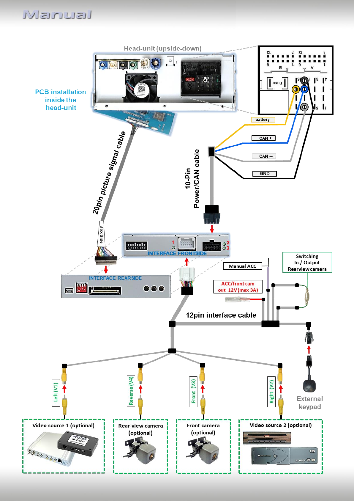
2.2. Connection scheme
Version 10.02.2023 HW CAM(V100) / (V20.3) RL4-A40
Page 10
Pag
e10
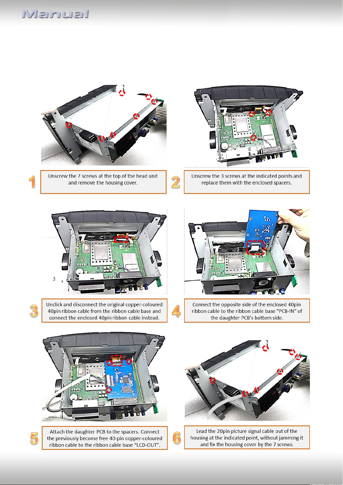
2.3. Installation – daughter PCB
Remove the factory monitor and open the head-unit`s housing. The daughter PCB is built to
be installed into the optical lead between the monitor panel and mainboard of the vehicles
monitor.
Version 10.02.2023 HW CAM(V100) / (V20.3) RL4-A40
Page 11
Pag
e11
2.3.1. Warning notes, concernin the installation of ribbon cables
1) The contacting ends of ribbon cables always have to be installed in a straight and precise
180° position to the connector. Each deviation from a perfect contact position will curse
faulty contact and even danger of short circuit
2) The ribbon cable’s contacting side always has to correspond to the contacting side of the
connector, concerning the mounting position.
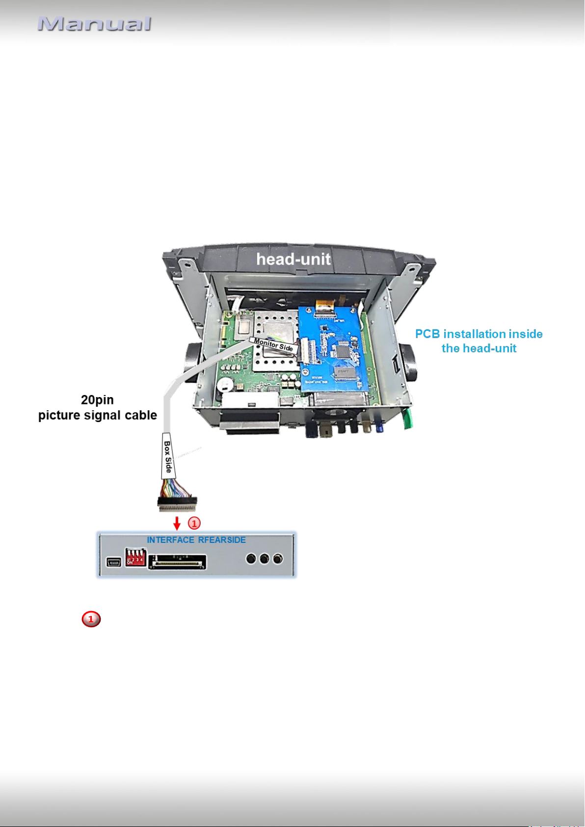
2.4. Connection – 20pin picture signal cable
Connect the female 20pin connector of the daughter PCB’s pre-connected 20pin
picture signal cable to the video interface’s male 20pin connector.
Version 10.02.2023 HW CAM(V100) / (V20.3) RL4-A40
Page 12
Pag
e12
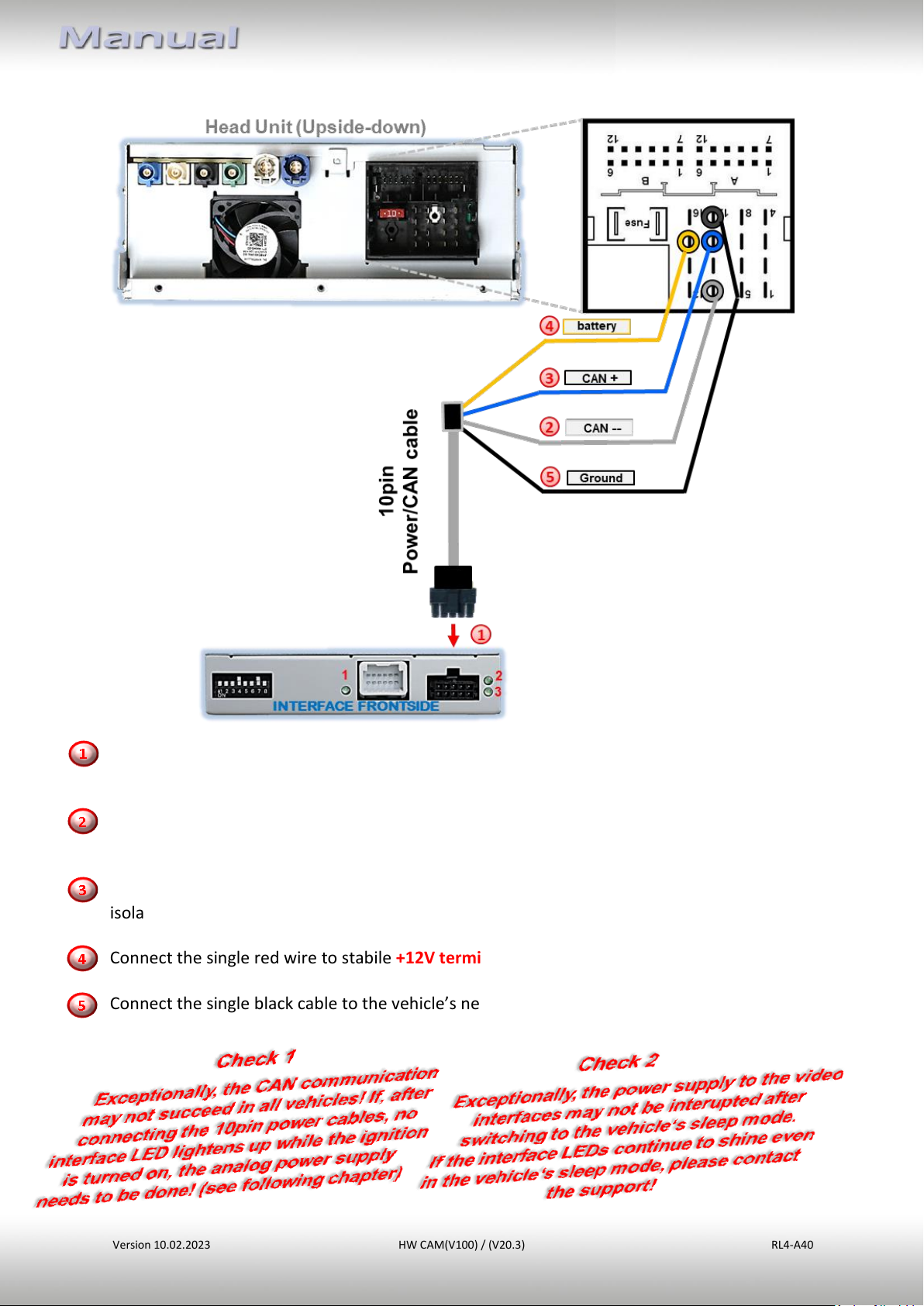
2.5. Connection – 10pin Power / CAN cable
Connect the enclosed 10pin Power / CAN cable’s female10pin connector to the male 10pin
connector of the video interface.
Connect the single grey wire „CAN LOW“ of the 4 cables to the vehicle’s CAN low wire and
isolate the connection
Connect the single blue wire „CAN HIGH“ of the 4 cables to the vehicle’s CAN high wire and
isolate the connection
Connect the single red wire to stabile +12V terminal 30.
Connect the single black cable to the vehicle’s negative Ground.
Version 10.02.2023 HW CAM(V100) / (V20.3) RL4-A40
Page 13
Pag
e13
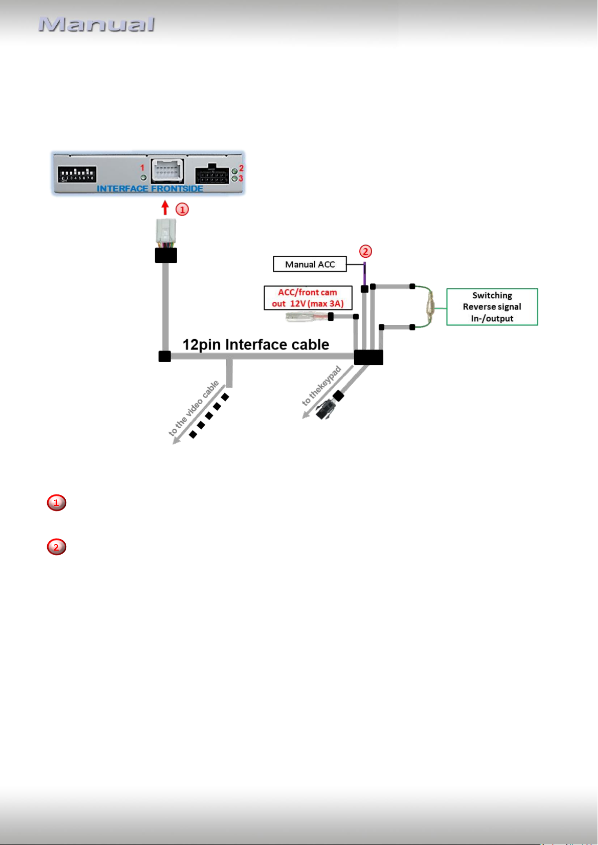
2.6. Analog power supply
If the communication between the CAN box and the vehicle’s CAN bus does not succeed (not
all vehicles are compatible), the analogue connection is required.
Connect the female 12pin connector of the 12pin interface cable to the male 12pin
connector of the video interface.
Connect the 12pin interface cable’s purple coloured wire Manual ACC to +12V Ignition power
or to +12V S-contact terminal 86s +12V (e.g. glove compartment illumination).
Version 10.02.2023 HW CAM(V100) / (V20.3) RL4-A40
Page 14
Pag
e14
Dip
Function
Dip 1 ON
+12V (max. 3A) when reverse gear is engaged plus 10 seconds delay
after reverse gear is disengaged and
+12V when manually switched to front camera by keypad (short press)
Dip 1 OFF
+12V permanent (max. 3A) ACC
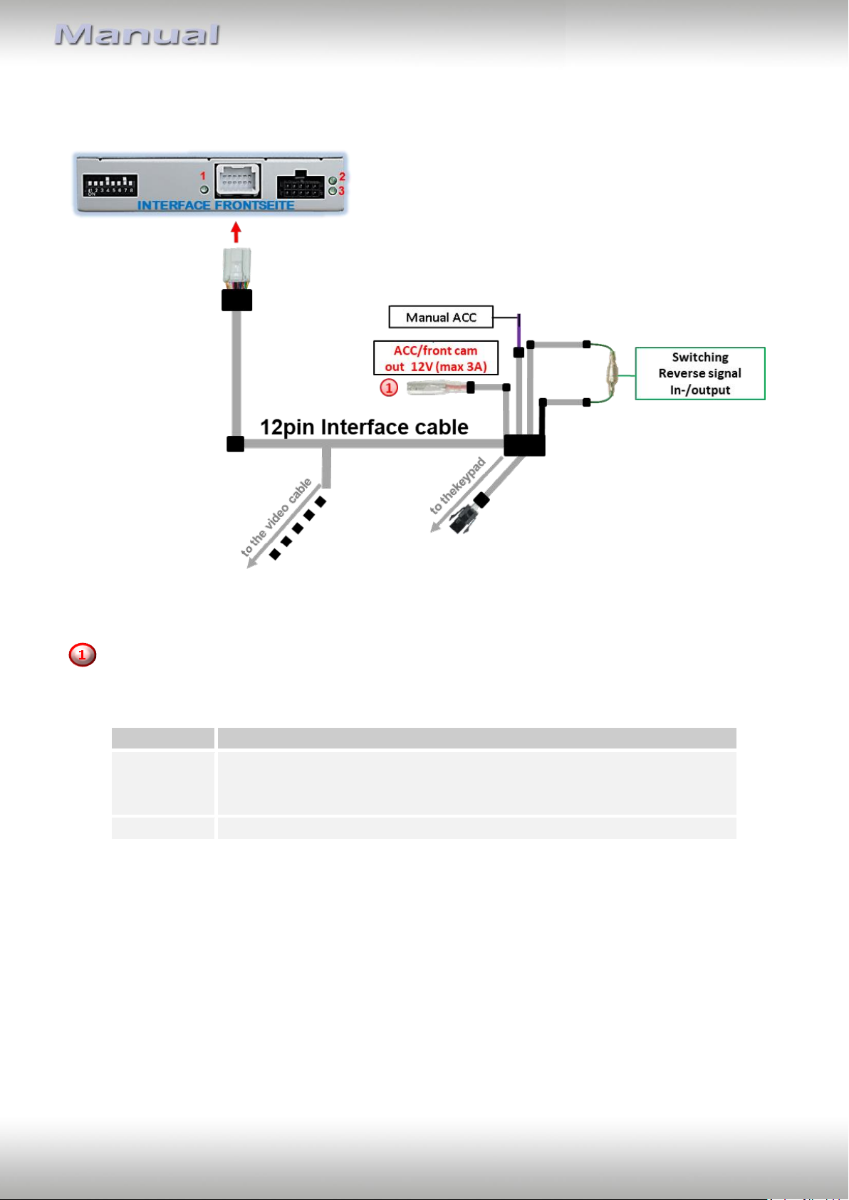
2.7. Power supply output
The red power supply output ACC/front cam out 12V (max 3A) can be used to power an
external source and has a different assignment, depending on the position of dip switch 1
(of 8 dips):
Version 10.02.2023 HW CAM(V100) / (V20.3) RL4-A40
Page 15
Pag
e15
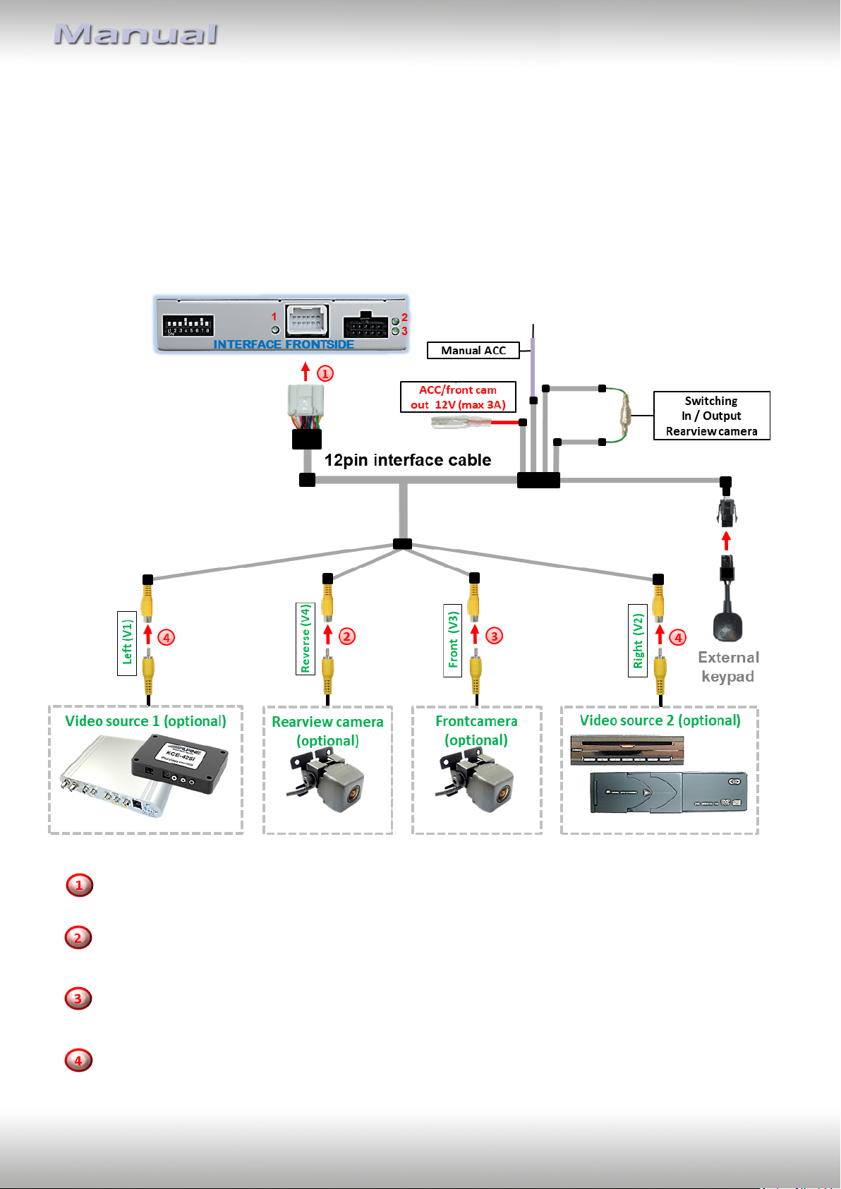
2.8. Connection – Video sources
It is possible to connect an after-market rear-view camera, an after-market front camera and
two more video sources to the video-interface.
Before the final installation, we recommend a test-run to detect a incompatibility of
vehicle and interface. Due to changes in the production of the vehicle manufacturer
there’s always a possibility of incompatibility.
Connect the 12pin interface cable’s female 12pin connector to the male 12pin connector of
the video-interface.
Connect the video RCA of the Rear-view camera to the 12pin interface cable’s female
RCA connector „Reverse V4.
Connect the front camera’s video RCA connector to the 12pin interface cable’s female
RCA connector „Front V3“.
Connect the video RCA of the AV source 1 and 2 to the 12pin interface cable’s female RCA
connector “Left (V1)” and ”Right (V2)”.
Version 10.02.2023 HW CAM(V100) / (V20.3) RL4-A40
Page 16
Pag
e16
2.8.1. Audio insertion
This interface is only able to insert video signals into the factory infotainment. If an AVsource is connected, the audio insertion has to be done by the factory audio AUX input or an
FM-modulator. The inserted video-signal can be activated simultaneously to each audiomode of the factory infotainment. If 2 AV sources shall be connected to the infotainment,
additional electronic is necessary to switch the audio signals.
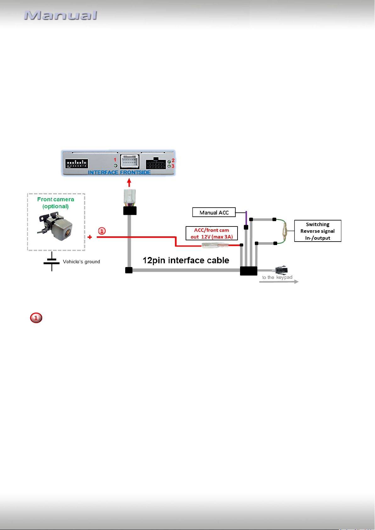
2.8.2. After-market front camera
The red power supply output ACC/front cam out 12V (max 3A) can be used to power a front
camera. If Dip 1 is set to ON (black 8 dips), the power supply output gives +12V (max 3A)
when reverse gear is engaged plus 10 seconds delay after reverse gear is disengaged.
Note: In addition, a manual switch-over to the front camera input is possible via keypad
(short press) from any image mode. The power supply output gives +12V then, as well (if Dip
1 is set to ON and the front camera input is selected).
Attention: A long press of the external keypad push button will switch the interface to the
next source.
Version 10.02.2023 HW CAM(V100) / (V20.3) RL4-A40
Page 17
Pag
e17
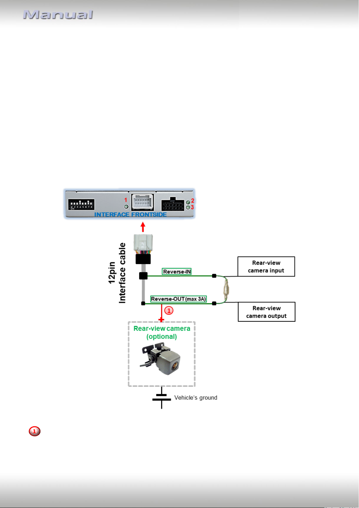
2.8.3. After-market rear-view camera
Some vehicles have a different reverse gear code on the CAN-bus which doesn’t
communicate with the interface’s CAN. In this case there are two different ways of
installation. If the interface’s CAN is able to detect an enabled vehicle’s reverse gear, the
green wire of the 12pin cable should carry +12V while the reverse gear is engaged.
Note: Do not forget to set dip5 of video-interface to ON before testing.
2.8.3.1. Case 1: Interface receives the reverse gear signal
If the interface receives +12V on the green wire of the 12pin interface cable while reverse
gear is engaged, the video interface will automatically switch to the rear-view camera input
“CAMERA-IN” while the reverse gear is engaged.
The 12 V power supply for the rear-view camera (max 3A) has to be taken from the 12pin
interface cabl’s green wire “Reverse-OUT” to avoid an unnecessary, permanent power
supply to the camera electronic.
Both green cables “Reverse IN” and “Reverse OUT” have to remain connected.
Version 10.02.2023 HW CAM(V100) / (V20.3) RL4-A40
Page 18
Pag
e18
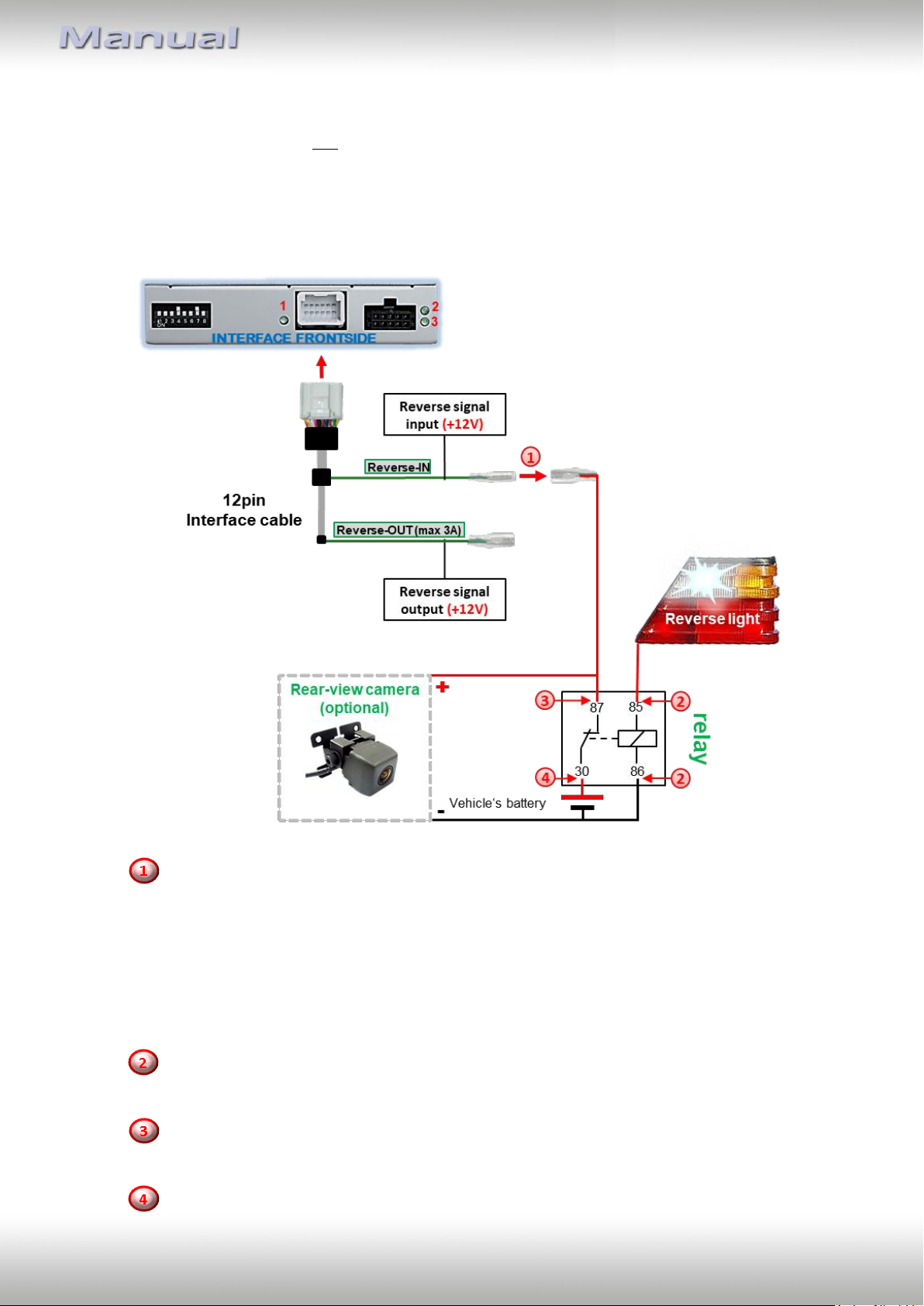
2.8.3.2. Case 2: Interface does not receive the reverse gear signal
If the video interface does not receive +12V on the green wire of the 12pin interface cable
when reverse gear is engaged (not all vehicles are compatible), an external switching signal
from the reverse gear light is required. As the reverse gear light’s power supply isn’t voltagestable all the time, an ordinary open relay (e.g AC-RW-1230 with wiring AC-RS5) or filter (e.g.
AC-PNF-RVC) is required. The diagram below shows the connection type of the relay.
Disconnect the green cable’s pre-connected male- and female connectors of the
12pin cable and connect the green input cable “Reverse-IN” to the output connector
(87) of the relay.
Note: Not least to avoid short circuits, the best solution should be, to crimp a male
4mm connector to the relay’s output cable and connect it to the green cable’s female
4mm connector. The output-cable “Reverse-OUT” remains disconnected as it’s out of
function.
Connect the Reverse light’s power-cable to coil (85) and the vehicle’s ground to coil
(86) of the relay.
Connect the output connector (87) of the relay to the rear-view camera’s powercable, like you did it to the green “Reverse-IN” cable before.
Connect permanent power / 12V to the relay’s input connector (30).
Version 10.02.2023 HW CAM(V100) / (V20.3) RL4-A40
Page 19
Pag
e19
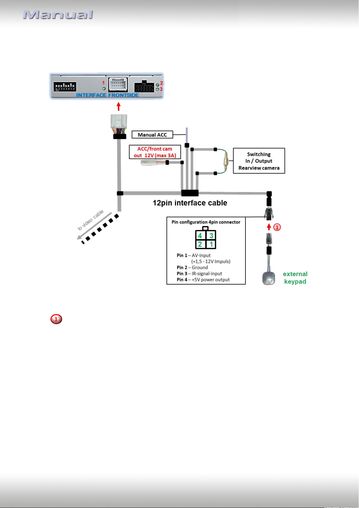
2.9. Connection – external keypad
Connect the keypad’s female 4pin connector to the 12pin interface cable’s male 4pin
connector.
Note: Even if the switching through several video sources by the keypad mightn’t be
required, the keypad’s invisible connection and availability is strongly recommended.
Version 10.02.2023 HW CAM(V100) / (V20.3) RL4-A40
Page 20
Pag
e20
3. Interface operation by external keypad
The interface’s external keypad can be used to switch the enabled inputs.
Long press of keypad (2-3 seconds)
By long pressing the external keypad (2-3 seconds), the video interfaces witches the input
from the factory video to the inserted video sources.
Each press (approx. 2 sec) will switch to the next enabled input. If all inputs are enabled the
order is:
Factory video video IN1 video IN2 factory video …
Disabled inputs will be skipped.
Note: The interface switches after releasing the switch (after long pressure).
Short press of keypad (only if DIP 1 is set to ON)
By short pressing the external keypad, the video interfaces switches from the factory video
to the front camera input and back to factory video.
Version 10.02.2023 HW CAM(V100) / (V20.3) RL4-A40
Page 21
Pag
e21
4. Picture settings
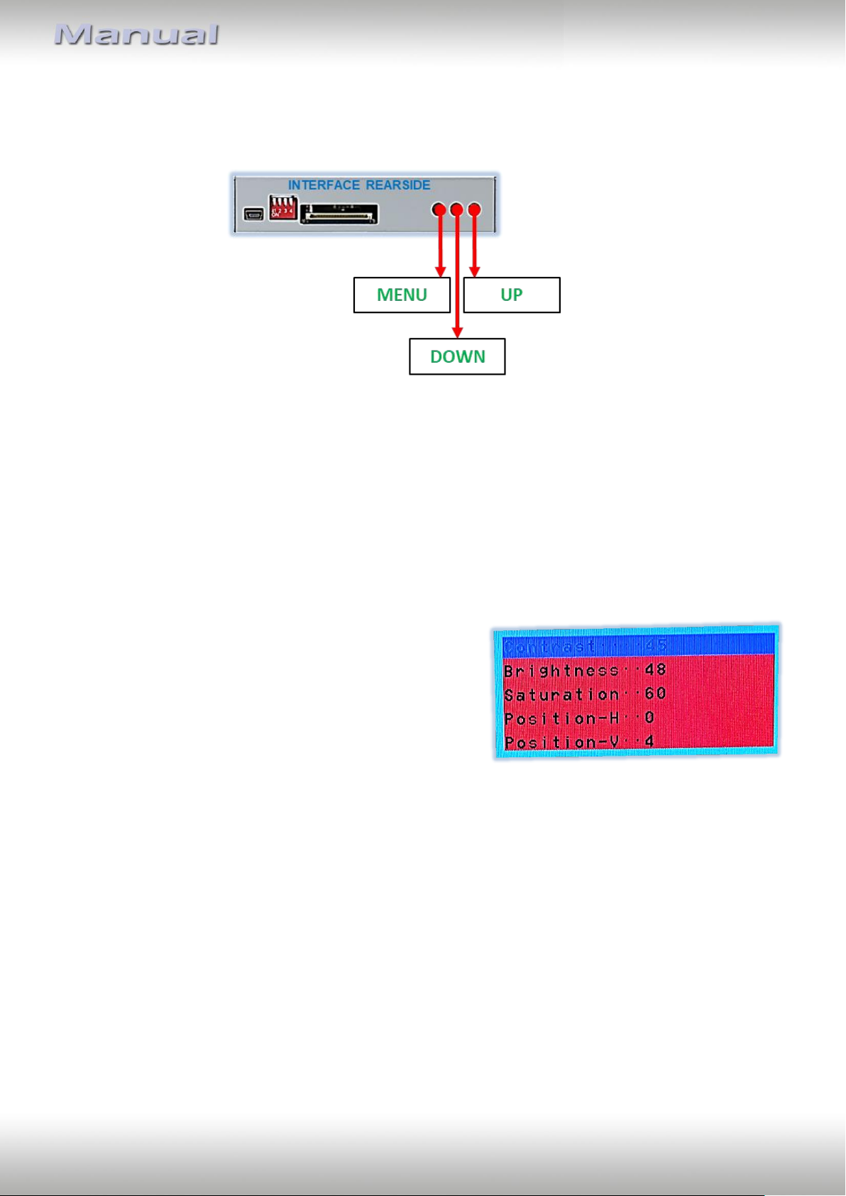
The picture settings are adjustable by the 3 push-buttons of the daughjter PCB’s menu
keypad. Press the 1. button to open the OSD settings menu or to switch to the next menu
item. By pressing the other both push buttons the selected value will be changed. To avoid
accidental changes during or after the installation, we recommend to disconnect the keypad
from the pushbutton cable after the adjustments are done. Adjustments have to be done,
while the selected input is visible on the monitor.
Note: The OSD menu is only shown when a working video source is connected to the
selected video-input of the interface.
The following settings are available:
Contrast
Brightness
Saturation
Position H (horizontal picture position)
Position V (vertical picture position)
Note: To adjust the reverse picture settings, engage the reverse gear.
5. Specifications
BATT/ACC range 7V - 25V
Stand-by power drain 10mA
Power 140mA @12V
Video input 0.7V - 1V
Video input formats NTSC
Temperature range -40°C to +85°C
Dimensions Video-box 117 x 26 x 90mm (W x H x D)
Dimensions daughter PCB 100 x 6 x 68mm (W x H x D)
Version 10.02.2023 HW CAM(V100) / (V20.3) RL4-A40
Page 22
Pag
e22
Symptom
Reason
Possible solution
No picture/black
picture (factory
picture).
Not all connectors have been
reconnected to factory headunit or monitor after
installation.
Connect missing connectors.
No power on CAN-bus box (all
LED CAN-bus box are off).
Check power supply of CAN-bus box. Check CAN-bus
connection of CAN-bus box.
CAN-bus box connected to
CAN-bus in wrong place.
Refer to the manual where to connected to the CANbus. If not mentioned, try another place to connect to
the CAN-bus.
No power on video-interface
(all LED video-interface are
off).
Check whether CAN-bus box delivers +12V ACC on red
wire output of 8pin to 6pin cable. If not cut wire and
supply ACC +12V directly to video-interface.
No picture/black
picture/white picture
(inserted picture) but
factory picture is OK.
No picture from video source.
Check on other monitor whether video source is OK.
No video-source connected to
the selected interface input.
Check settings dips 1 to 3 of video interface which
inputs are activated and switch to corresponding
input(s).
LVDS cables plugged in wrong
place.
Double-check whether order of LVDS cables is exactly
connected according to manual. Plugging into headunit does not work when the manual says to plug into
monitor and vice versa.
Wrong monitor settings of
video-interface.
Try different combinations of dips 7 and 8 of videointerface. Unplug 6pin power after each change.
Inserted picture totally
wrong size or position.
Inserted picture double
or 4 times on monitor.
Inserted picture
distorted, flickering or
running vertically.
Video sources output set to
AUTO or MULTI which causes
a conflict with the interfaces
auto detection.
Set video source output fixed to PAL or NTSC. It is best
to set all video sources to the same standard.
If error occurs only after
source switching: Connected
sources are not set to the
same TV standard.
Set all video sources to the same standard.
Some interfaces can only
handle NTSC input.
Check manual whether there is a limitation to NTSC
mentioned. If yes, set source fixed to NTSC output.
Inserted picture b/w.
Inserted picture qual.
bad.
Picture settings have not been
adjusted.
Use the 3 buttons and the interface's OSD to adjust the
picture settings for the corresponding video input.
Inserted picture size
slightly wrong.
Inserted picture
position wrong.
Camera input picture
flickers.
Camera is being tested under
fluorescent light which shines
directly into the camera.
Test camera under natural light outside the garage.
Camera input picture is
bluish.
Protection sticker not
removed from camera lens.
Remove protection sticker from lens.
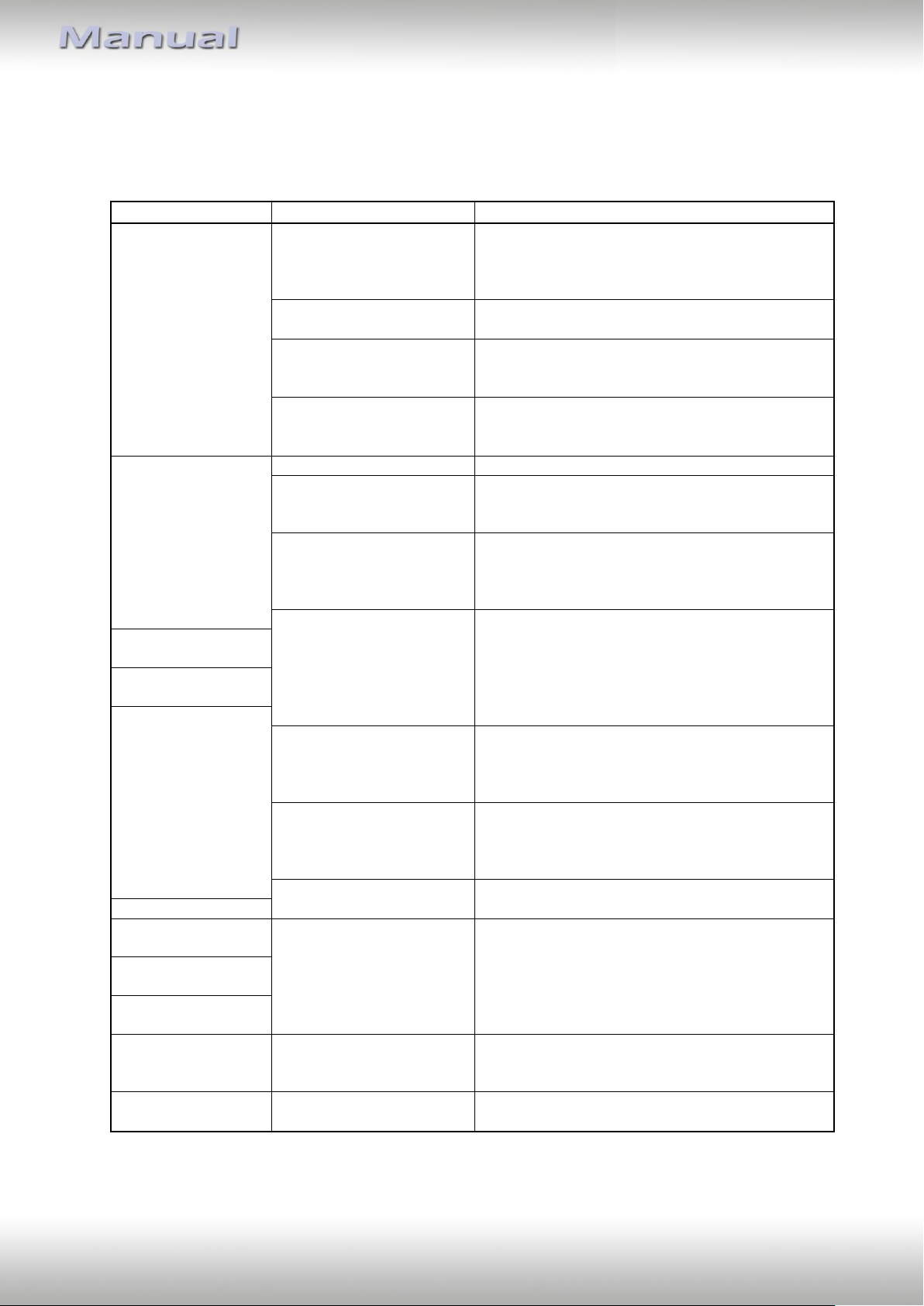
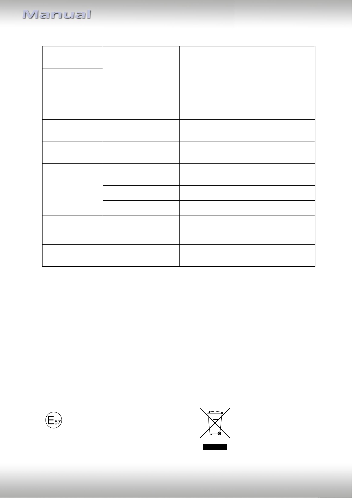
6. FAQ – Trouble shooting Interface functions
For any troubles which may occur, check the following table for a solution before requesting
support from your vendor.
Version 10.02.2023 HW CAM(V100) / (V20.3) RL4-A40
Page 23
Pag
e23
Symptom
Reason
Possible solution
Camera input picture
black.
Camera power taken directly
from reverse gear lamp.
Use relay or electronics to "clean" reverse gear lamp
power. Alternatively, if CAN-bus box is compatible
with the vehicle, camera power can be taken from
green wire of 6pin to 8pin cable.
Camera input picture
has distortion.
Camera input picture
settings cannot be
adjusted.
Camera input picture settings
can only be adjusted in AV2
mode.
Set dip 3 of video-interface to ON (if not input AV2 is
not already activated) and connect the camera to AV2.
Switch to AV2 and adjust settings. Reconnect camera
to camera input and deactivate AV2 if not used for
other source.
Graphics of a car in
camera input picture.
Function PDC is ON in the
interface OSD.
In compatible vehicles, the graphics will display the
factory PDC distance. If not working or not wanted, set
interface OSD menu item UI-CNTRL to ALLOFF.
Chinese signs in
camera input picture
Function RET or ALL is ON
(function for Asian market) in
the interface OSD.
Set interface OSD menu item UI-CNTRL to ALLOFF or
PDCON.
Not possible to switch
video sources by OEM
button.
CAN-bus interface does not
support this function for
vehicle.
Use external keypad or cut white wire of 6pin to 8pin
cable and apply +12V impulses for AV-switching.
Pressed too short.
For video source switching a longer press of about 2.5
seconds is required.
Not possible to switch
video sources by
external keypad.
SW-version of interface does
not support external keypad.
Use OEM-button or cut white wire of 6pin to 8pin
cable and apply +12V impulses for AV-switching.
Interface does not
switch to camera input
when reverse gear is
engaged.
CAN-bus interface does not
support this function for the
vehicles.
Cut the green wire of the 6pin to 8pin cable and apply
+12V constant from reverse gear-lamp signal. Use
relay to "clean" R-gear lamp power.
Interface switches
video-sources by itself.
CAN-bus interface
compatibility to vehicle is
limited.
Cut the grey wire of 6pin to 8pin and isolate both
ends. If problem still occurs, additionally cut the white
wire of 6pin to 8pin cable and isolate both ends.
Made in China
7. Technical Support
Please note that direct technical support is only available for products purchased directly
from NavLinkz GmbH. For products bought from other sources, contact your vendor for
technical support.
NavLinkz GmbH
distribution/tech dealer-support
Heidberghof 2
D-47495 Rheinberg
Tel +49 2843 17595 00
Email [email protected]
10R-05 0068
Version 10.02.2023 HW CAM(V100) / (V20.3) RL4-A40
 Loading...