

Page 1

CAN-bus Interface
Steering wheel control
Interface-box
CX-401
Harnesses vehicle-specific
CX-0xx
Harnesses device-specific (optional)
ARC-1xx
Product features
• Conversion of digital CAN-bus signals into analogue signals
ACC, speed, lights, reverse gear, park distance control (optional cable CX-LS necessary)
• Adaptation of vehicle-specific radio ports to female ISO-connectors
(for some vehicles only a universal harness with open ends available)
• Support/Starting of factory sound systems
(not at all vehicles)
• Steering wheel control for after-market devices (optional)
Alpine, Blaupunkt, Clarion, Digitaldynamic, JVC, Kenwood, Pioneer, Zenec
• With USB update-port for software-updates by consumer
Version 18.12.2024 CX-401
Page 2

Seite
1
"
Contents
1. Prior to installation
1.1. Delivery contents
1.2. Check compatibility of vehicle
1.3. Setting the DIP switches
1.4. Setting of internal switch for Pioneer devices (as of HW-VER V3.0)
2. Installation
2.1. Assignment of the 12pin Molex on CX-401
2.2. CX-401 LED functions
2.3. Connection example
2.4. Installation with vehicle-specific harness CX-0xx
2.5. Installation with universal harness CX-010
2.6. Installation acoustic signal of park distance control with CX-PI200(till SW 1.1.2)
2.7. Installation acoustic signal of park distance control with CX-LS (from SW 1.1.3)
2.8. Steering wheel functions
2.9. Onboard computer control Citroen and Peugeot for after-market radios
3. Vehicle-specific assignments CAN-bus
4. Specifications
5. Technical support
Information
Changes/updates of the vehicle’s software can cause malfunctions of the interface. We offer
free software-updates for our interfaces for one year after purchase. To receive a free
update, the interface must be sent in at own cost. Labor cost for and other expenses
involved with the software-updates will not be refunded.
Version 18.12.2024 CX-401
Page 3
Seite
2
"
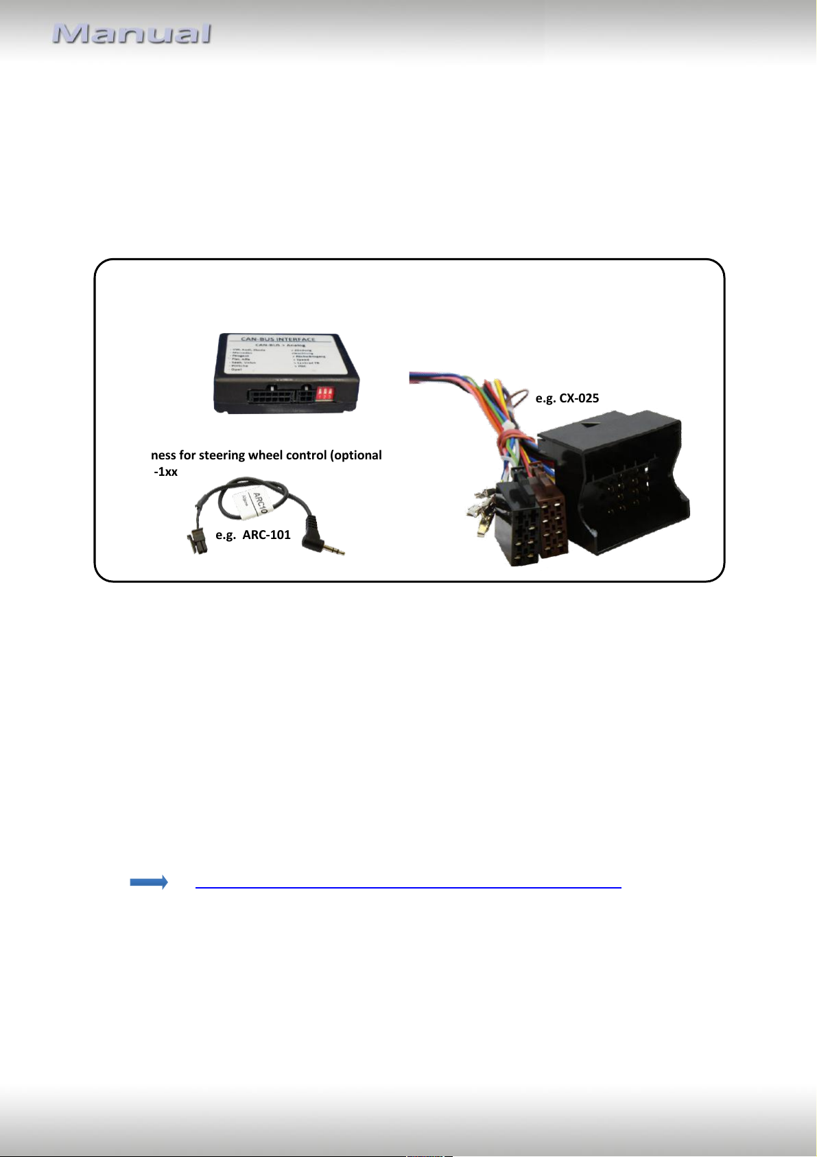
e.g. CX-025
CAN-box
CX-401
HW_____
SW _____
Take down the SW-version and HW-version of the CAN-box, and store this manual
for support purposes.
There is always a universal or vehicle-specific
cable set CX-0xx needed.
Harness for steering wheel control (optional)
ARC-1xx
e.g. ARC-101
1. Prior to installation
Read the manual prior to installation. Technical knowledge is necessary for installation. The
place of installation must be free of moisture and away from heat sources.
1.1. Delivery contents
1.2. Check compatibility of vehicle
The CX-401 provides depending on the vehicle ignition (I), speed signal (S), reverse gear (R),
lighting (L), acoustic signal of park distance control (PDC) as an analogue signal, it powers up
an existing factory sound-system (SS), allows the using of on-board computer system control
(OCS) and supports the control of after market devices by steering wheel (SWC).
The link to the table shows which harness CX-0xx can be used for which vehicles and which
functions of the CX-401 will be supported for this vehicle.
https://downloads.casgermany.com/can_bus_compatibility.pdf
Version 18.12.2024 CX-401
Page 4
Seite
3
"
Harness
Description
DIP1
DIP2
DIP3
ARC-103
Control cable set for Blaupunkt (Mini-ISO connection)
on
off
off
ARC-104
Control cable set for Alpine
off
off
off
Control cable set for Clarion
on
on
off
Control cable set for JVC (Mini-Jack connection)
on
off
on
ARC-105
Control cable set for Kenwood (open wire)
on
on
on
Control cable set for JVC (open wire)
on
off
on
ARC-106
Control cable set for Kenwood (DIN-connection)
on
on
on
ARC-107
Control cable set for Pioneer
off
on
on
Blaupunkt (Mini-Jack connection)
off
on
off
ARC-108
Control cable set for Zenec and Digitaldynamic
off
off
on
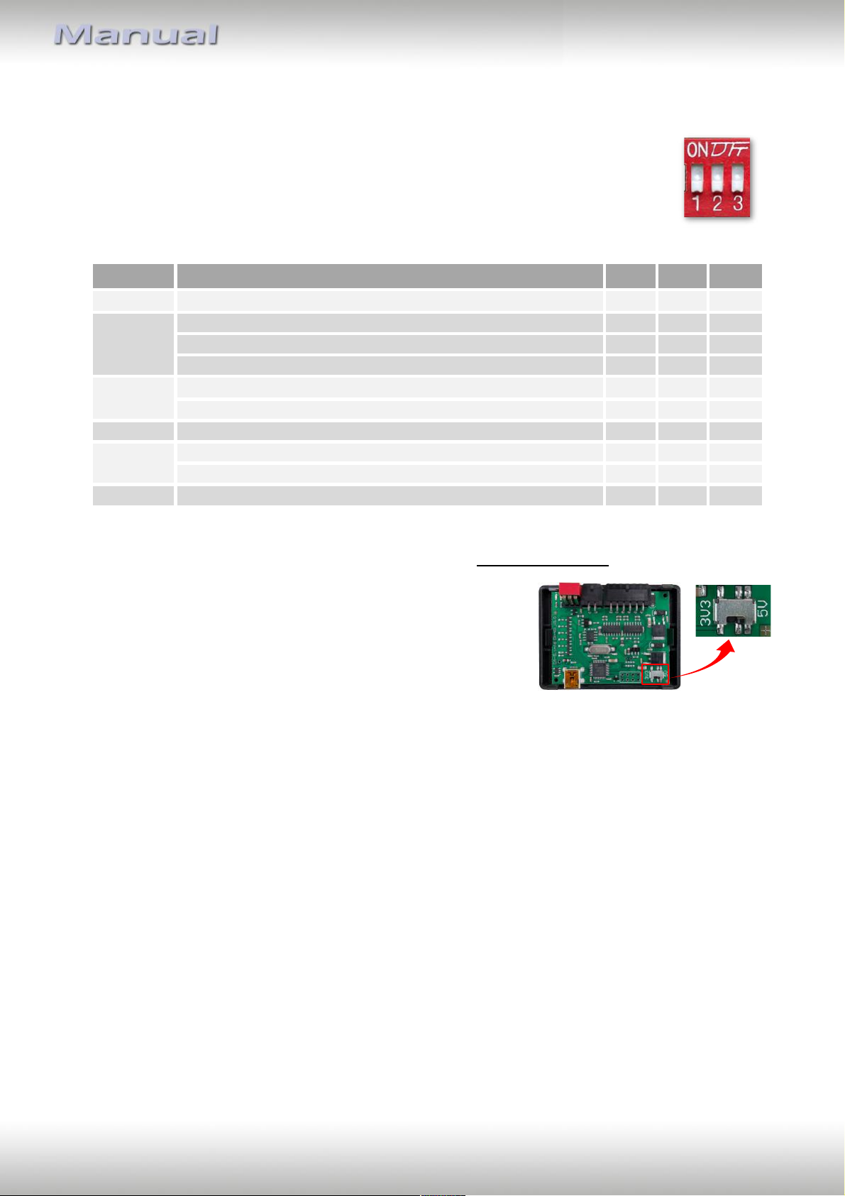
1.3. Setting the DIP switches
To use the steering wheel control is dependent on the manufacturer of the
after-market device a device-specific IR control cable ARC-1xx needed.
The DIP sitches of the CAN-box CX-401 have to be set on the manufacturer/ port.
The following table shows the IR control cable and the DIP switch settings for the
supported manufacturers.
1.4. Setting of internal switch for Pioneer devices (as of HW-VER V3.0)
When the steering wheel control with a Pioneer will not
work (DIP1 OFF | DIP2 ON | DIP3 ON), then open the
housing of the interface and change the switch position
from 5V to 3.3V.
2. Installation
Switch off ignition and disconnect the vehicle’s battery! If according to factory rules
disconnecting the battery has to be avoided, it is usually sufficient to put the vehicle in
sleep-mode. In case the sleep-mode does not show success, disconnect the battery with a
resistor lead.
Place of installation of the CX-401 is usually in the radio slot on the vehicle’s radio port.
Version 18.12.2024 CX-401
Page 5

Seite
4
"
Cable colour
Assignment
Pin 1 ● pink
+12V ACC (Output) max.1.5A
Pin 2 ● blue
CAN-LOW (Input)
Pin 3 ●● yellow/green (●● yellow/red)
Speed signal (Output)
Pin 5 ● red
+ signal PDC (harness CX-LS)
Pin 6 ● red
+12V Permanent (Input)
Pin 7 ● orange
Lights (Output) max. 0.1A
Pin 8 ● yellow
CAN-HIGH (Input)
Pin 9 ● white
Reverse gear (Output) max. 1.5A
Pin 11 ● black
Ground signal PDC (harness CX-LS)
Pin 12 ● black
Ground
LED
Status
Funktion
● Red
Lights
Ignition is ON
● Blue
Flashes
CAN Bus is searched
● Blue
Lights
CAN Bus found
2.1. Assignment of the 12-pin Molex on CX-401
2.2. CX-401 LED functions
Version 18.12.2024 CX-401
Page 6
Seite
5
"
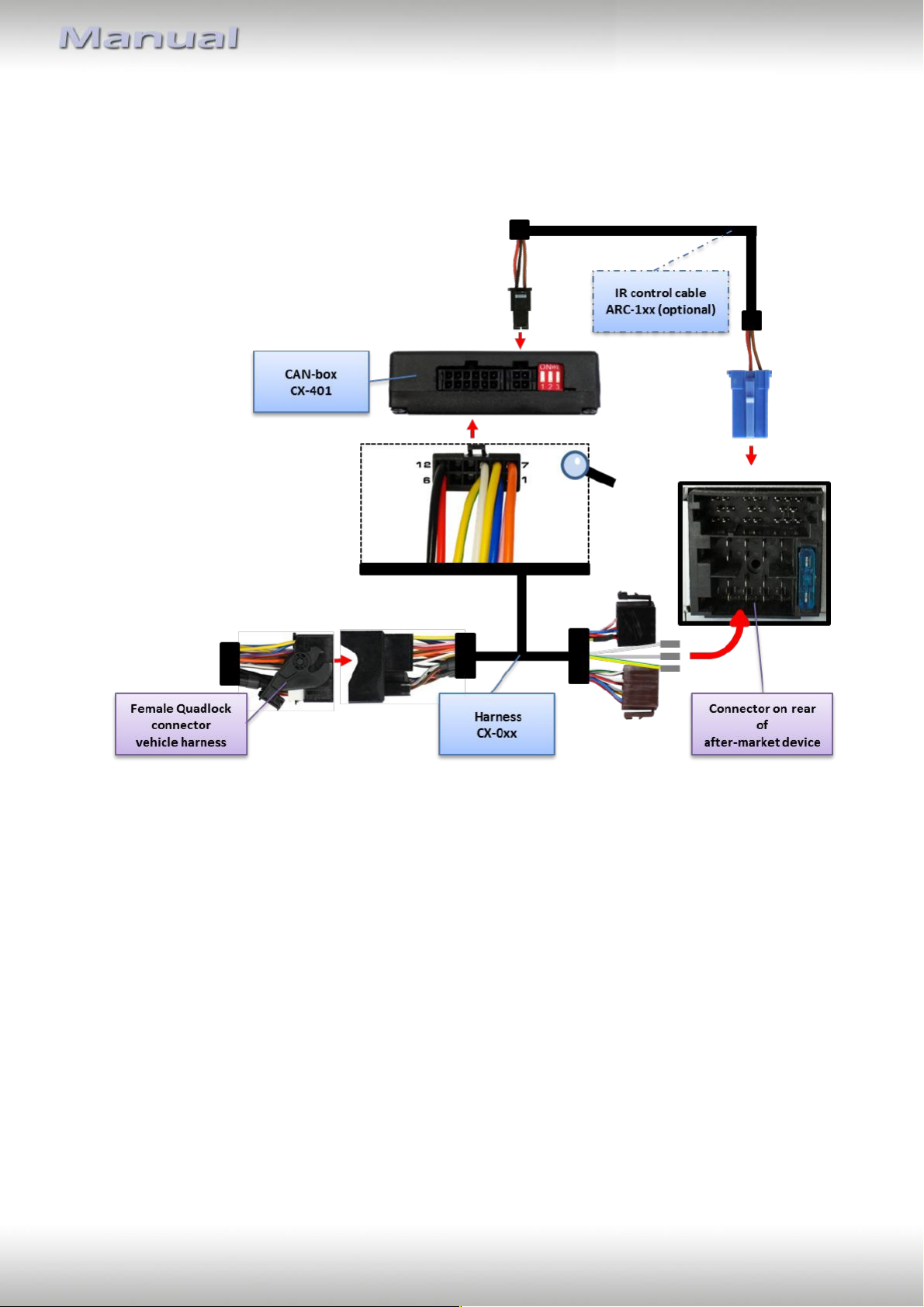
2.3. Connection example
Example of vehicle-specific harness CX-025 and IR control cable ARC-102 to a Blaupunkt
head-unit.
Version 18.12.2024 CX-401
Page 7

Seite
6
"
2.4. Installation with vehicle-specific harness CX-0xx
a.) Persistent current, Ground, ACC signal (Z) and lights signal (L) are pinned in the
female ISO-connector of the CX-0xx. If supported by the CX-401 connect speed signal
(S) and reverse gear signal (R) to the corresponding pins of the after-market device.
b.) Depending on equipment/vehicle the grey cable is occupied with the analogue phone
mute signal. Connect to the corresponding pins of the after-market device.
c.) Connect vehicle’s female radio connector(s) to the corresponding male connector(s)
of harness CX-0xx.
d.) Connect harness CX-0xx to CAN-Box CX-401 via 12pin Molex.
e.) Connect female ISO-connectors of harness CX-0xx to the ISO-connector of the after-
market device.
f.) Optional: Connect IR-control input of the after-market device to the 4pin Molex IR-
control output of CAN-box CX-401 via the optional control cable ARC-1xx.
Note for CX-035 (Ford): ACC and illumination are not digital but analogue signals on some
vehicles. In this case connect ACC (Quadlock, chamber A, pin 16; pink wire) and illumination
(Quadlock, chamber A, pin 13; orange wire) between female 12pin MicroFit connector and
female ISO connectors, using the plugs of the harness.
2.5. Installation with universal harness CX-010
a.) Connect universal harness CX-010 according to assignment of 12pin Molex on CX-
401 to harness of the after-market device and to vehicle harness.
b.) Optional: Connect IR-control input of the after-market device to the 4pin Molex IR-
control output of CAN-box CX-401 via the optional control cable ARC-1xx.
Version 18.12.2024 CX-401
Page 8
Seite
7
"
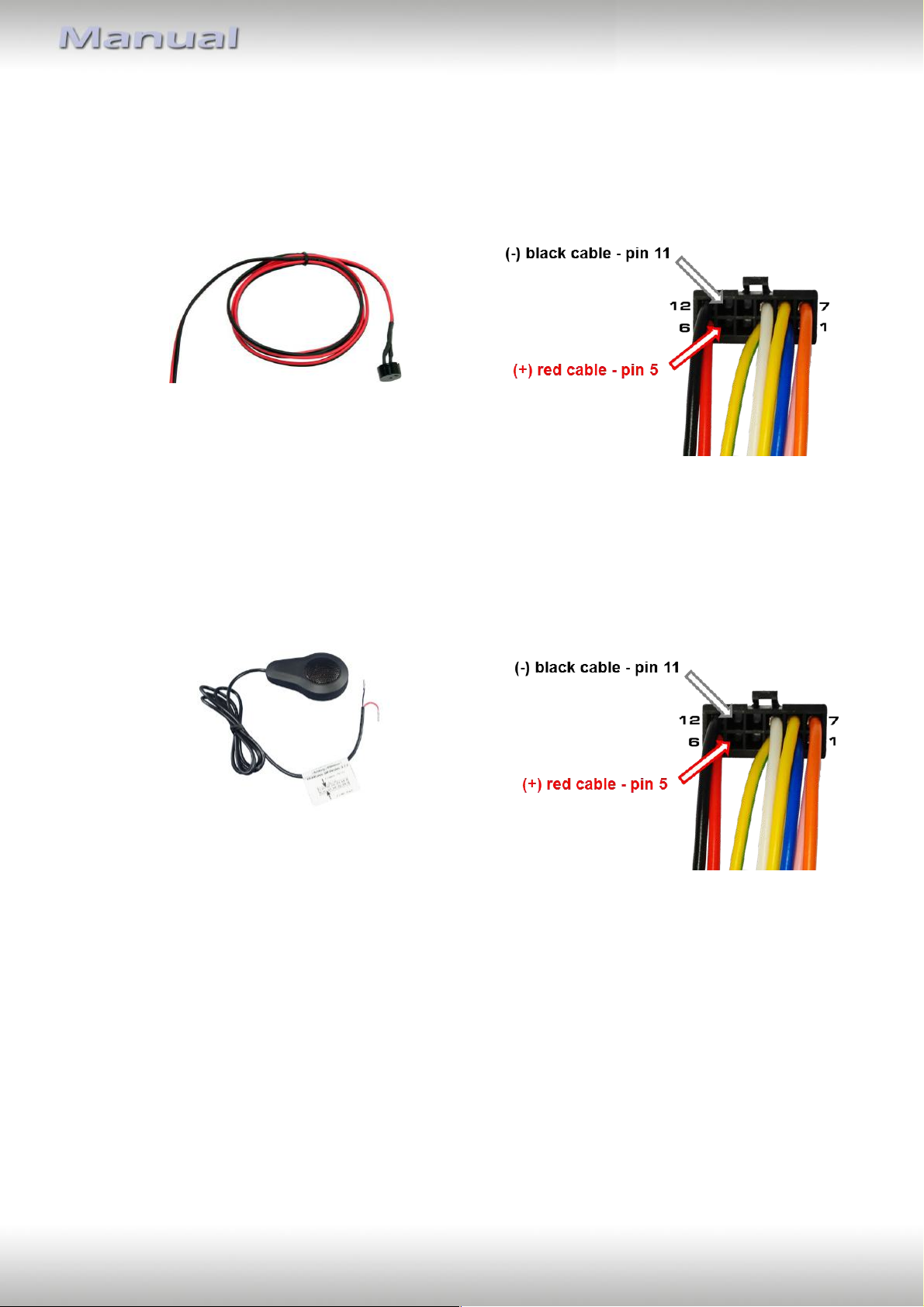
CX-PI200
CX-LS
2.6. Installation acoustic signal of park distance control with CX-PI200 (till SW 1.1.2)
a.) Connect the black and red cable of the CX-PI200 (Piezo LSP to CX-028/CX-030/CX-
033/CX-010) into the correlative pins of the female 12pin Molex connector of harness
CX-0xx:
2.7. Installation acoustic signal of park distance control with CX-LS (from SW 1.1.3)
b.) Connect the black and red cable of the CX-LS (LSP to CX-028/CX-030/CX-033/CX-010)
into the correlative pins of the female 12pin Molex connector of harness CX-0xx:
Version 18.12.2024 CX-401
Page 9

Seite
8
"
Button
Function
Vehicle / radio support
VOLUME + / -
Volume up / volume down
All vehicle brands ,
all radio brands
TRACK + / -
Next track / radio station,
previous track / radio station
All vehicle brands ,
all radio brands
SOURCE
Source switching
Compatible vehicle brands,
all radio brands
MUTE
Mute ON/OFF
Compatible vehicle brands,
all radio brands
PICK UP PHONE /
HANG UP PHONE
Answer call /
end call
Compatible vehicle brands,
all radio brands
PHONE
Answer call OR end call
Compatible vehicle brands,
all radio brands
VOICE CONTROL
Activation of voice control
Compatible vehicle brands,
compatible radio brands
2.8. Steering wheel functions
2.9. Onboard computer control Citroen and Peugeot for after-market radios
To control the onboard computer in Citroen and Peugeot vehicles the following functions
can be selected by steering-wheel buttons:
Select Menu long pressing "Source" (4s)
ESC short pressing "Source"
OK Vol+
Menu up Wheel up
Menu down Wheel down
Menu Right Track+
Menu Left TrackMode long pressing "Tr+" (4s)
Dark long pressing "Tr-" (4s)
Assignment of the steering-wheel buttons:
Tr+ pick up phone
Tr- hang up phone
Wheel up Tr+
Wheel down Tr-
The assignments of the remaining steering-wheel buttons are identical to the label!
Version 18.12.2024 CX-401
Page 10
Seite
9
"
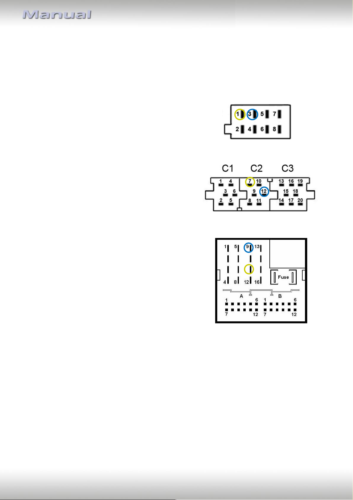
3. Vehicle-specific assignments - CAN-bus
As additional support the following pages give information about some vehicle-specific CANbus pin definitions. This information is subject to change and must be verified by the
installer.
ALFA ROMEO
147
Female 8-Pin ISO connector in radio slot
CAN High – Pin 1
CAN Low – Pin 3
AUDI
A2, A3, A4, A6 till 01/05
Female Mini-ISO connector in radio slot
CAN High – Pin 7
CAN Low – Pin 12
BMW
1series E81, 3series E90, 5series E60
Female Quadlock-connector in radio slot
CAN High – Pin 11
CAN Low – Pin 9
Version 18.12.2024 CX-401
Page 11
Seite
10
"
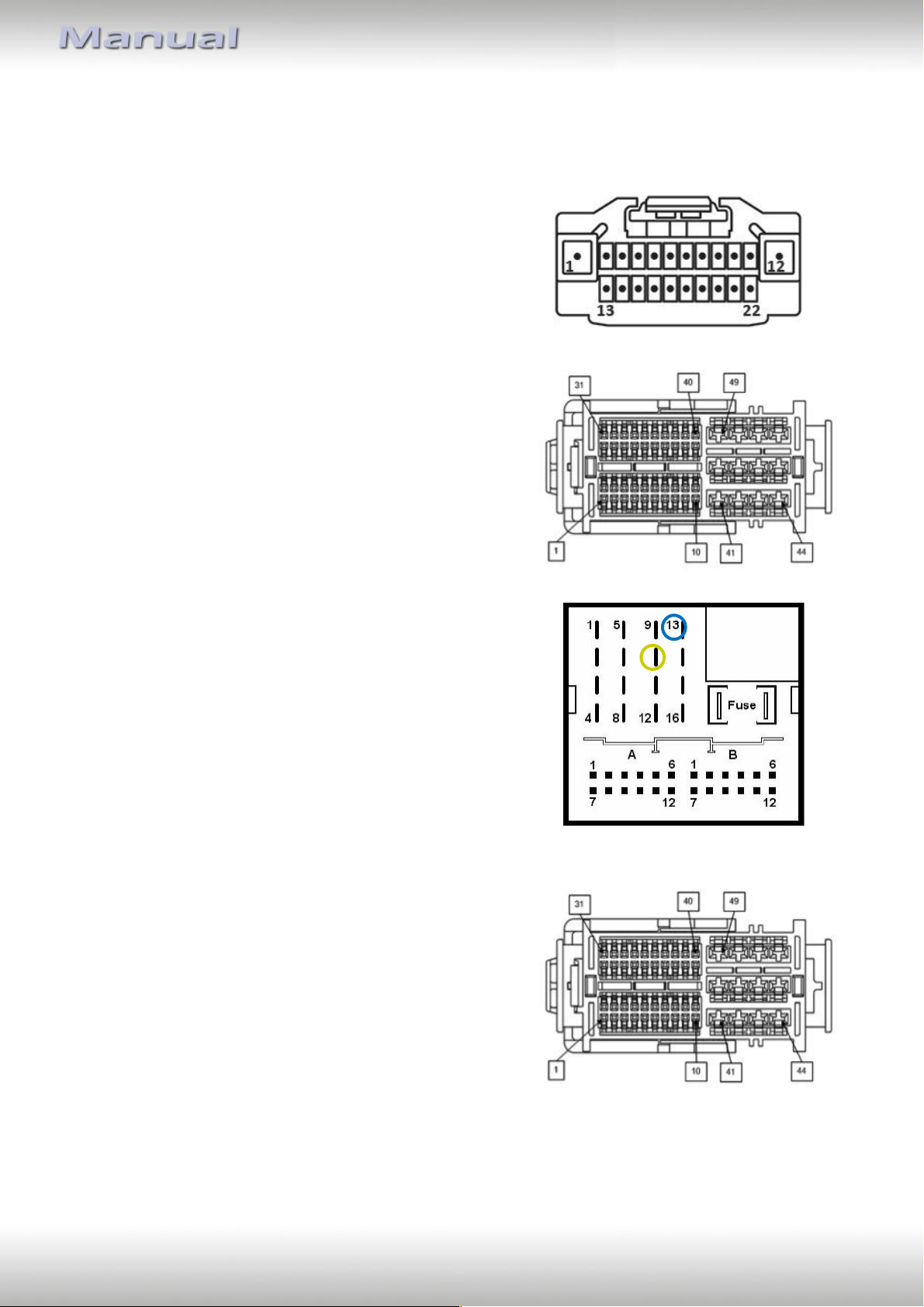
Chrysler
Chrysler cars with female 22pin connector in radio slot
CAN High – Pin 10
CAN Low – Pin 13
Chrysler cars with female 52pin connector in radio slot
CAN High – Pin 2
CAN Low – Pin 12
CITROËN
C4, C5 from 10/04
Female Quadlock-connector in radio slot
CAN High – Pin 10
CAN Low – Pin 13
Jumper II
Female 52pin connector in radio slot
CAN High – Pin 2
CAN Low – Pin 12
Version 18.12.2024 CX-401
Page 12
Seite
11
"
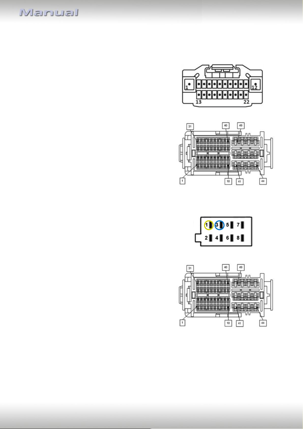
Dodge
Dodge cars with female 22pin connector in radio slot
CAN High – Pin 10
CAN Low – Pin 13
Dodge cars with female 52pin connector in radio slot
CAN High – Pin 2
CAN Low – Pin 12
FIAT
Stilo, 500
Female 8pin ISO connector in radio slot
CAN High – Pin 1
CAN Low – Pin 3
Ducato as of 2013
Female 52pin connector in radio slot
CAN High – Pin 2
CAN Low – Pin 12
Version 18.12.2024 CX-401
Page 13
Seite
12
"
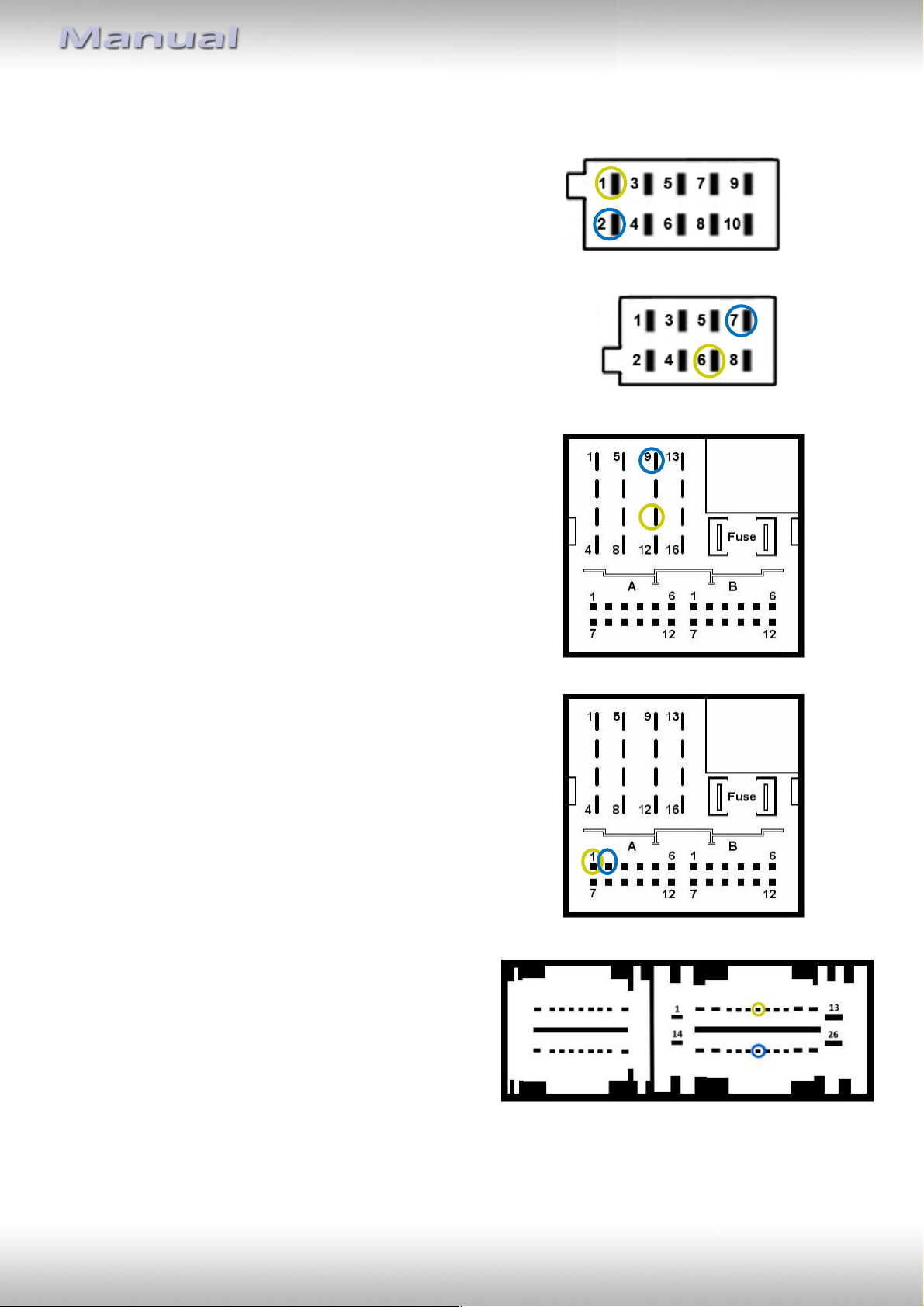
1
20
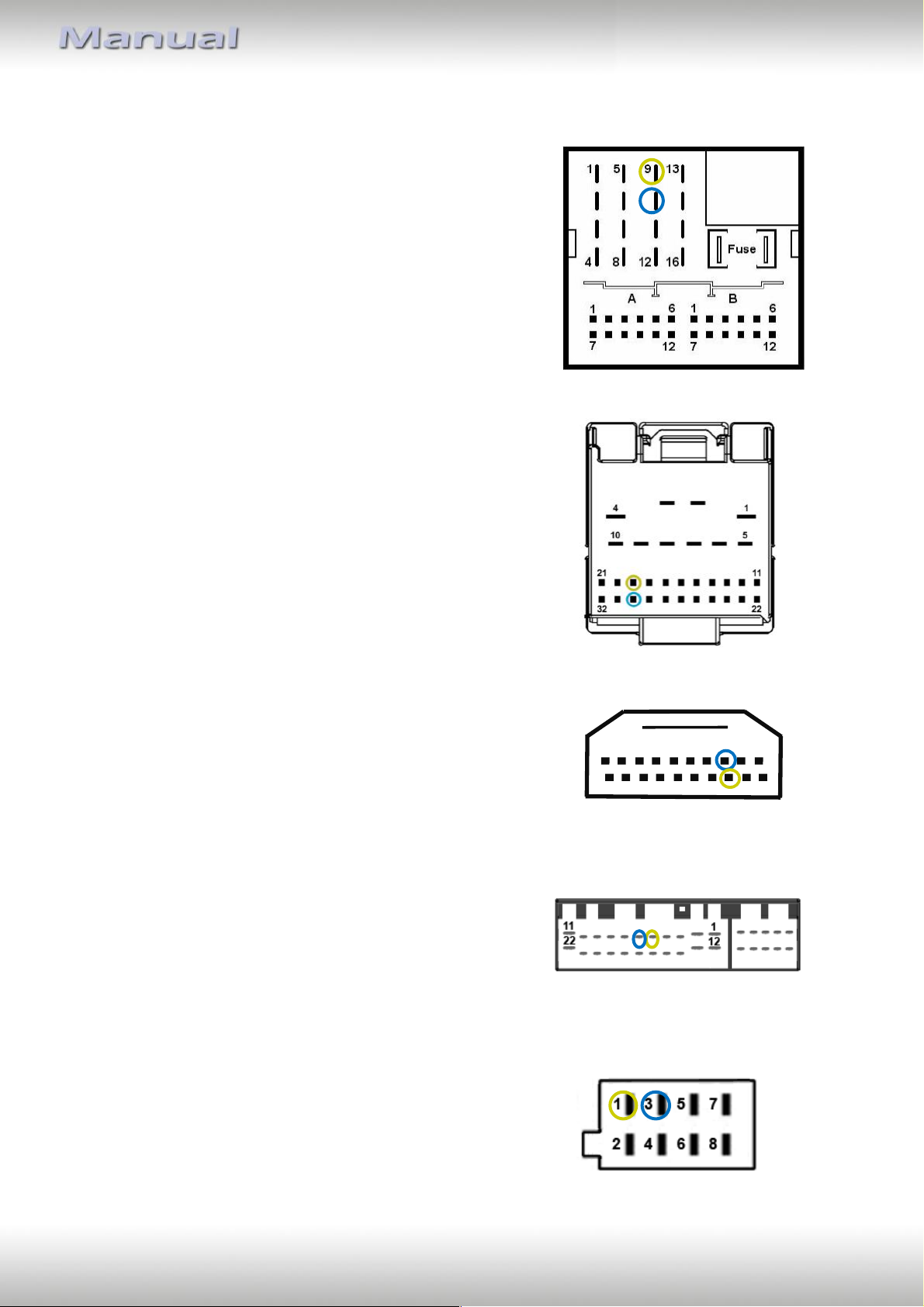
FORD
Focus, Focus C-MAX, S-MAX, Mondeo
Female Quadlock connector in radio slot
CAN High – Pin 9
CAN Low – Pin 10
Fiesta, Transit, Transit Custom, Transit Connect
Female 32pin connector in radio slot
CAN High – Pin 19
CAN Low – Pin 30
Honda
Accord (8G), CR-Z, Jazz (2G)
Female 20pin connector in radio slot
CAN High – Pin 13
CAN Low – Pin 3
JEEP/CHRYSLER
Grand Cherokee, 300C
Female 22-pin connector in radio slot
CAN High – Pin 5 (white / red)
CAN Low – Pin 6 (white)
LANCIA
Ypsilon from 11/03
Female 8-pin ISO connector in radio slot
CAN High – Pin 1
CAN Low – Pin 3
Version 18.12.2024 CX-401
Page 14
Seite
13
"
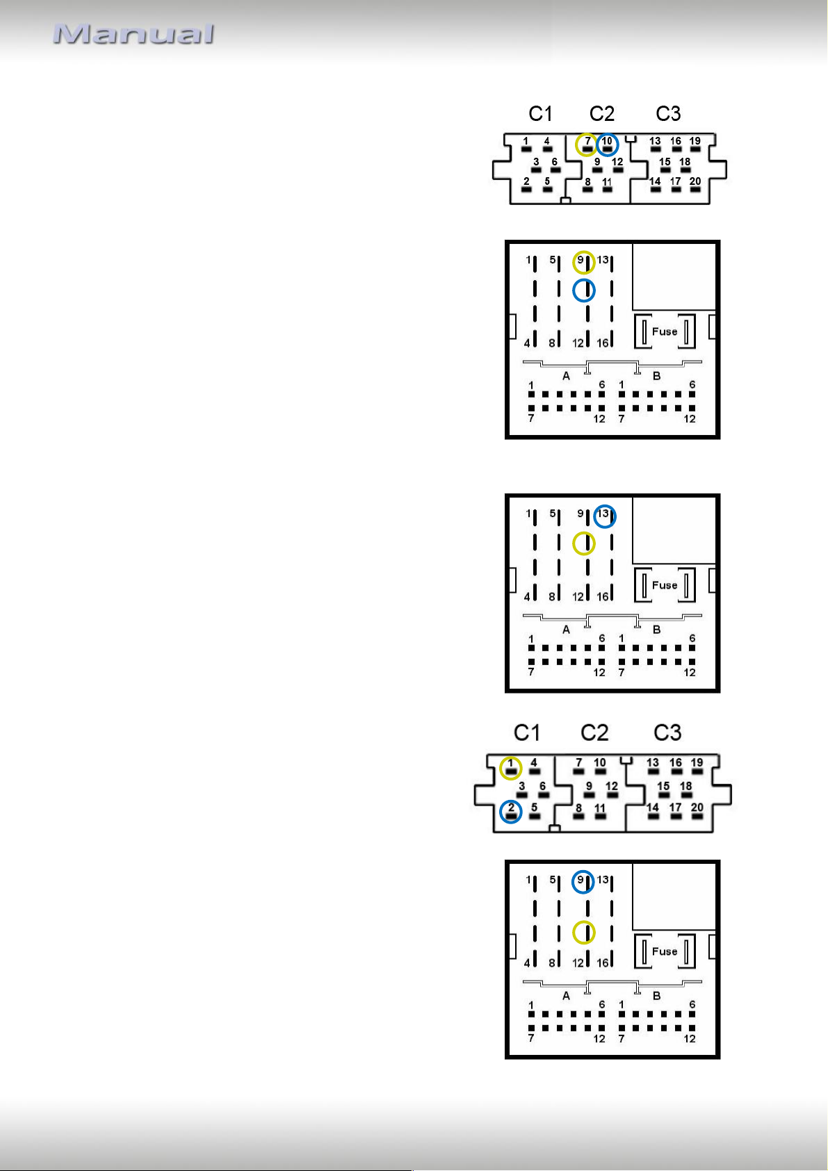
MERCEDES BENZ
CLK W208 after facelift, CLK W209 till 03/04,
E-Class W210 from 09/99, Viano, SL W230 from 07/04
Female 10pin ISO-connector in radio slot
CAN High – Pin 1
CAN Low – Pin 2
A-Class W169 and B-Class W245 with Audio5,
all MERCEDES with indoor CAN-bus
Female 8pin ISO connector in radio slot
CAN High – Pin 6
CAN Low – Pin 7
A-Class W169 and B-Class W245 with Audio20,
C-Class W203 and CLK W209 from 04/04,
Viano W693
Female Quadlock-connector in radio slot
CAN High – Pin 11
CAN Low – Pin 9
E-Class W211 from 04/03, CLS W219, SLK R171
Female Quadlock-connector in radio slot
CAN High – Pin 1 (Kammer A)
CAN Low – Pin 2 (Kammer A)
Sprinter W907/W910 from 12/07
Female 26pin connector in radio slot
CAN High – Pin 7
CAN Low – Pin 20
Version 18.12.2024 CX-401
Page 15
Seite
14
"
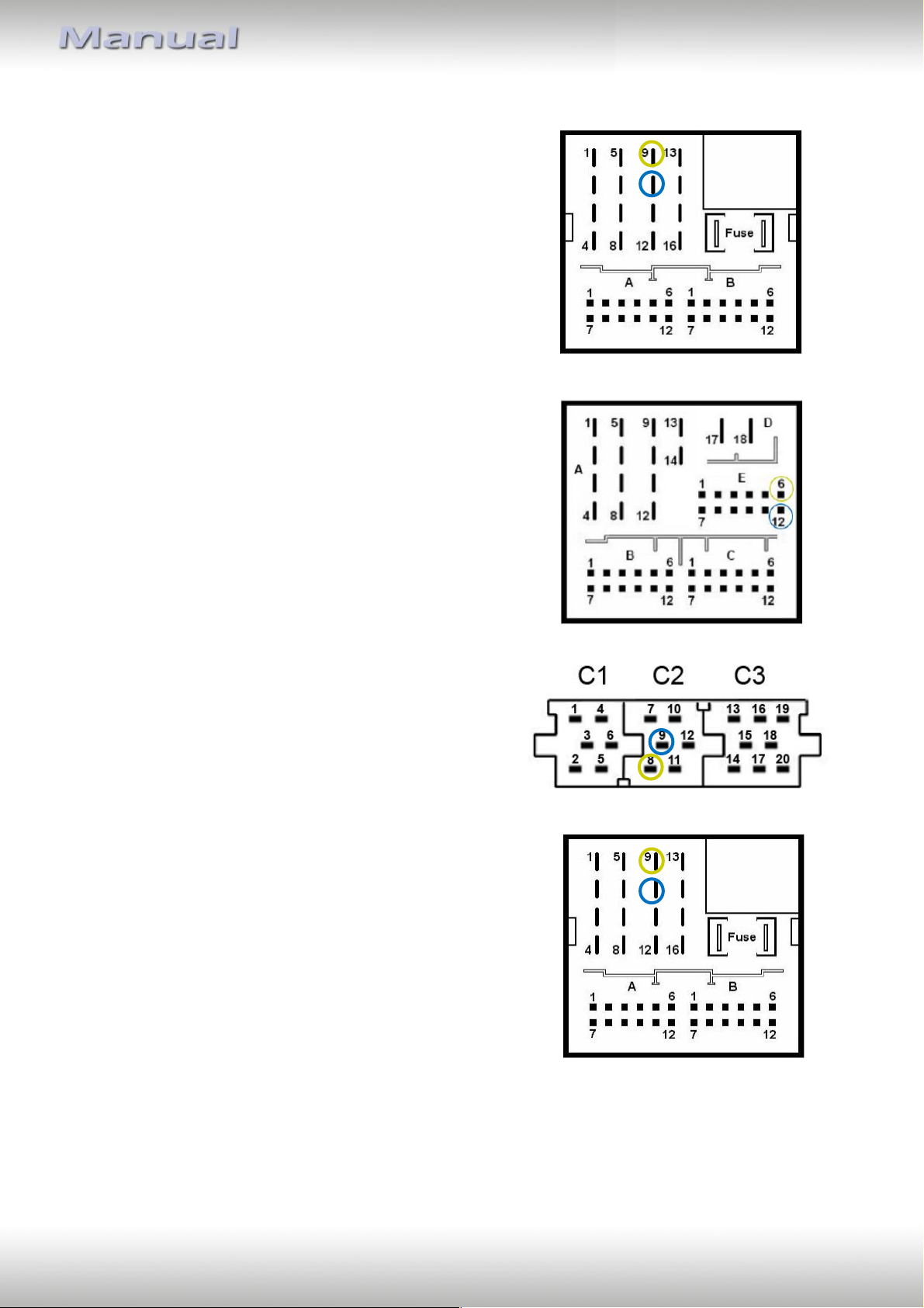
OPEL
Vectra C till 07/04
Female Mini-ISO connector in radio slot
CAN High – Pin 7
CAN Low – Pin 10
Astra H , Corsa C, Meriva, Tigra Twin Top,
Vectra C from 08/04
Female Quadlock-connector in radio slot
CAN High – Pin 9
CAN Low – Pin 10
PEUGEOT
307, 407
Female Quadlock-connector in radio slot
CAN High – Pin 10
CAN Low – Pin 13
PORSCHE
Cayenne (9PA), Boxster (987), 911 (997)
Female Mini-ISO connector in radio slot
CAN High – Pin 1
CAN Low – Pin 2
Cayenne (92A), Panamera (970)
Female Quadlock-connector in radio slot
CAN High – Pin 11
CAN Low – Pin 9
Version 18.12.2024 CX-401
Page 16
Seite
15
"
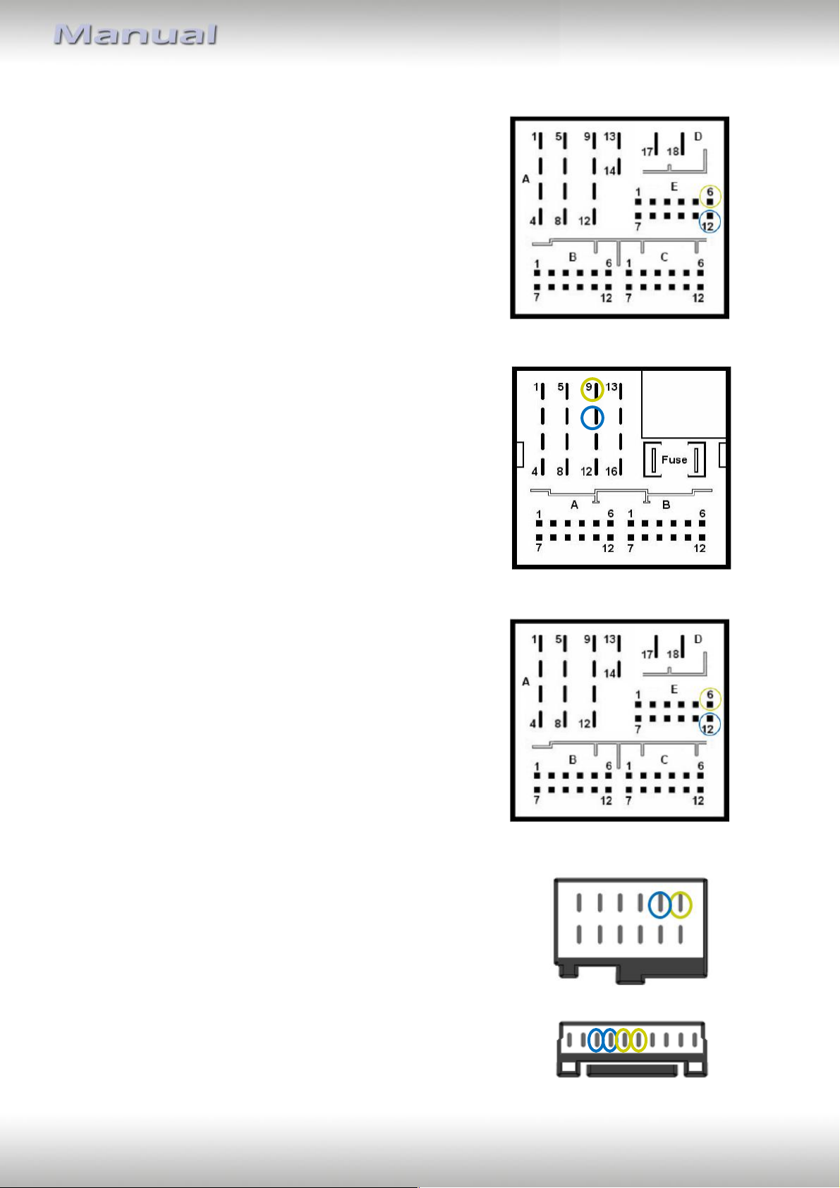
SEAT
Altea
Female Quadlock-connector in radio slot
CAN High – Pin 9
CAN Low – Pin 10
Leon III
Female Quadlock-connector in radio slot
CAN High – Pin 6
CAN Low – Pin 12
ŠKODA
Superb, Octavia I
Female Mini-ISO connector in radio slot
CAN High – Pin 8
CAN Low – Pin 9
Octavia II
Female Quadlock-connector in radio slot
CAN High – Pin 9
CAN Low – Pin 10
Version 18.12.2024 CX-401
Page 17
Seite
16
"
Fabia III
Female Quadlock-connector in radio slot
CAN High – Pin 6
CAN Low – Pin 12
VOLKSWAGEN
Golf 4, Golf 5, Passat 3B, Caddy, Touran,
Touareg, T5
Female Quadlock-connector in radio slot
CAN High – Pin 9
CAN Low – Pin 10
Golf 7
Female Quadlock-connector in radio slot
CAN High – Pin 6
CAN Low – Pin 12
VOLVO
S60, V70
Female 12pin connector in radio slot
CAN High – Pin 7 (white)
CAN Low – Pin 8 (green)
XC90
Female 10-Pin connector in radio slot
CAN High – white cable (double occupied)
CAN Low – green cable (double occupied)
Version 18.12.2024 CX-401
Page 18

Seite
17
"
4. Specifications
Operation voltage 10.5 – 14.8V
Stand-by power drain <3mA
Operation power drain ~50mA
Power consumption 0.07-40W
Temperature range -30°C till +80°C
Weight 38g
Measurements (box only) W x H x D 71 x 22 x 50 mm
Capacitance
ACC max. 1.5A
Reverse Gear max. 1.5A
Lights max. 0.1A
5. Technical Support
CAS GmbH
manufacturer/distribution
In den Fuchslöchern 3
D-67240 Bobenheim-Roxheim
email [email protected]
Legal disclaimer: Mentioned company and trademarks, as well as product names/codes are registered
trademarks ® of their corresponding legal owners.
Version 18.12.2024 CX-401
 Loading...