


Operating Manual
PS009900
The PS009900 amplifier is a single channel auxiliary amplifier for use with constant
envelope modulation formats such as FM, GMSK, BPSK and FSK. It is intended for use
with the MDS9710 Radio to augment the signal level to emulate an MCS2000 Radio for
railside communications.
PS009900 Operation Manual Rev C Page 1

Antenna Installation Warning
1. All antenna installation and servicing is to be performed by qualified technical
personnel only. When servicing the antenna, or working at distances closer than those
listed below, ensure the amplifier has been disabled. Output is measured at the
antenna terminal of the amplifier. The antenna(s) used for this amplifier must be fixedmounted on outdoor permanent structures to provide the minimum separation
distances described in this filing for satisfying RF exposure compliance requirements.
When applicable, RF exposure compliance may need to be addressed at the time of
licensing, as required by the responsible FCC Bureau(s), including antenna co-location
requirements of 1.1307(b)(3).
2. Typically, the antenna connected to the amplifier is a directional (high gain)
antenna, fixed-mounted on the side or top of a building, or on a tower. Depending
upon the application and the gain of the antenna, the total composite power could
exceed 450 watts EIRP. The antenna location should be such that it can only be
accessed by qualified technical personnel and that under normal operating conditions
no other person can touch the antenna or approach within 8 meters of the antenna.
RF Exposure
Separation distances required for FCC RF Exposure compliance
Antenna Gain vs. Recommended Safety Distance
Antenna Gain (dBi)
0–5 dBi 5–10 dBi 10-12 dBi
Minimum RF Safety
Distance
3.5 6.3 7.9
PS009900 Operation Manual Rev C Page 2

YRWK
12 Volts DC
Serial No. XXXXXX
FCC ID VMOPS009900
Model PS009900 Ver 2
Frequency 896-898 MHz
Power 30 Watts
IC: 7525A-PS009900
Figure 2 - Outline Drawing
Figure 1 - Control Connector Pinout
PS009900 Operation Manual Rev C Page 3

Overview
The PS009900 is designed to be inserted between a single channel 5 watt radio and an
antenna to provide performance enhancement. It amplifies a 5 watt signal from the
radio output to a 30 watt signal available to the antenna in the 896-898 MHz frequency
band. It contains a passive receive path for pass through of signals in the 935-938 MHz
frequency band. The unit operates from a nominal +12 VDC supply, requiring 7.5 amps
at 30 watts of output. Transmit is enabled with a logic controlled Push-to-Talk (PTT)
signal. The unit is passively cooled and is suitable for intermittent transmit operation to
20% duty cycle.
RF signal connection is through SMA (F) connectors. Supply voltage and PTT signal are
applied through a 9 pin D-Subminiature E Shell connector. The unit’s physical
dimensions are 5.8”x4.0”x1.6”. The amplifier may be attached to a user supplied
assembly using the integral 6-32 threaded mounting locations and suitable hardware
(not supplied).
WARNING
This amplifier is not configured for “hot switching”. PTT must not be engaged with the
radio transmit signal connected and transmit power from the radio or signal source
applied. Enabling the PTT logic with RF transmit signal applied my permanently
damage the amplifier.
WARNING
Avoid operating the amplifier without properly terminating the a ntenna p ort with a n
antenna or a suitable dummy load.
Interconnection
The PS009900 is intended for use as part of system to augment the transmit performance
of lower power radios. Specific implementation requires system knowledge regarding
the appropriate power levels to be used in the implementation. Consult manuals for
the radio and antenna to be used prior to installation.
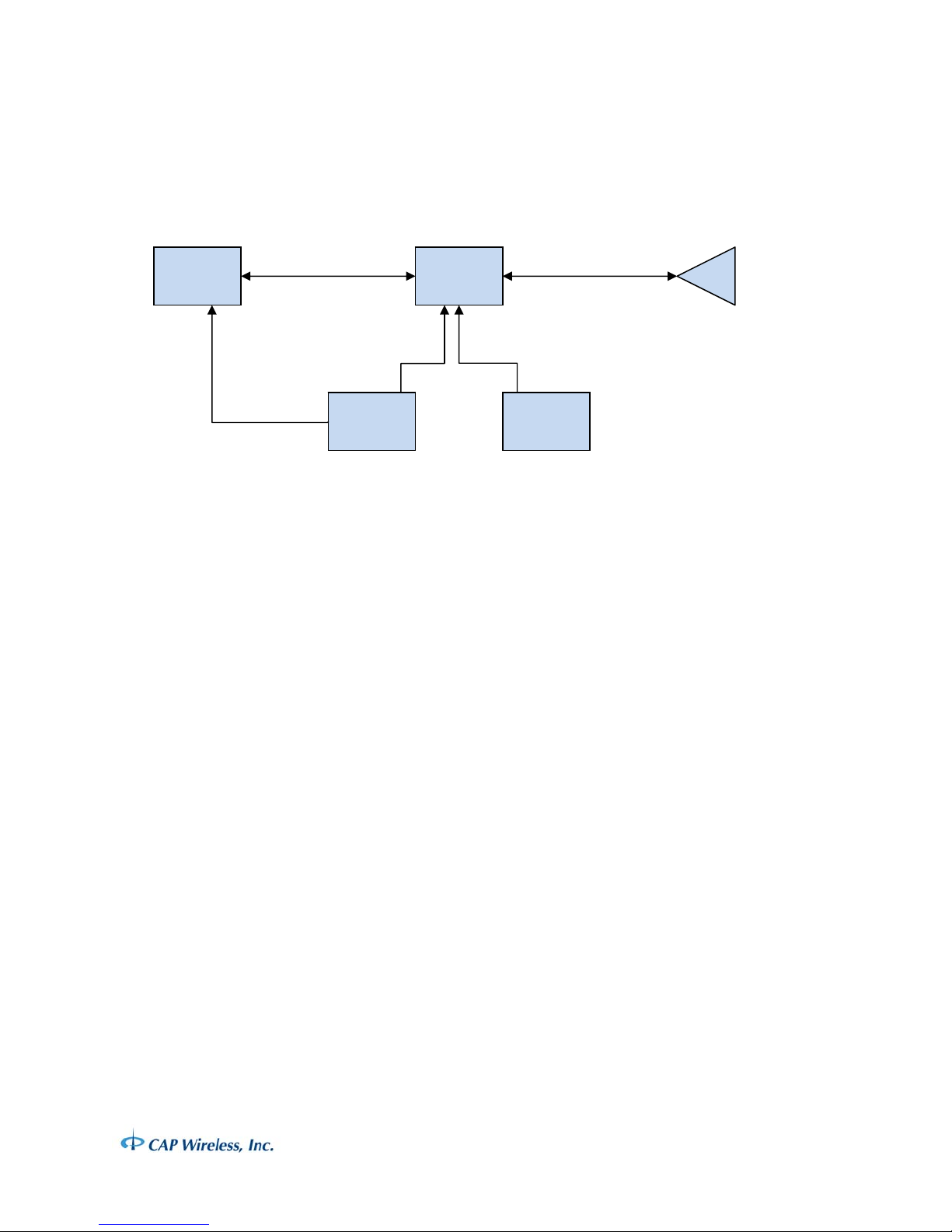
The PS009900 should be connected to the system as shown in Figure 3 - Interconnection
Block Diagram. High quality 50 ohm coaxial cables should be used for interconnection
between the radio, the amplifier and the antenna. The DC supply, return, PTT control
and return should be connected from the bias supply and controller, respectively, using
signal wire gauge appropriate to the amperage and wire length. Verify the wire
connections and pin configuration. The PTT control/Bias D connector shell should be
secured to the amplifier using appropriate hardware.
WARNING
PS009900 Operation Manual Rev C Page 4
Connection of the +12 volt Bias supply to the PTT pin of J3 will permanently damage the
r
unit.
Radio
or
Signal
J1 From
Radio
Bias/Cont
PS009900
Amplifier
J3
J2 To
Antenn
Antenn
PTT Signal
12 Volt
Supply
Figure 3 - Interconnection Block Diagram
Setup and Operation
Set the radio output to 5 Watts, but do not enable the radio transmit function. Verify the
radio transmit frequency is set to within the specified amplifier frequency. Enable the
PTT function on the amplifier by applying a TTL low (0 Volts) to J3, Pin 1. With PTT in
transmit mode (TTL low) but no RF input from the Radio, the amplifier should draw
approximately 650 mA from the DC supply at +12 Volts.
Enable the radio to transmit. Verify the transmit output power from the amplifier
antenna port is 30 watts. If needed, adjust the radio transmit power level to achieve
thirty watts. The amplifier should draw 7.5 A from the DC supply in this mode. Disable
the radio transmit function. Disable the PTT function by applying TTL High (5 volts) to J3
Pin 1.
NOTICE
The amplifier will default to PTT disabled if PTT signal logic is not connected. No transmit
capability will be available. The unit will not be damaged if RF transmit power is applied
to the radio input with PTT disabled, as long as the PTT signal is not applied with Radio
transmit power present.
WARNING
Avoid operating the amplifier continuously in transmit mode (PTT TTL Low) for longer
than five minutes at rated power (30 watts). If lengthy operation of the amplifier is
PS009900 Operation Manual Rev C Page 5

required for test or evaluation purposes, the amplifier must be cooled by supplying air
flow with a fan across the heat sink fins of the amplifier. For additi onal information
Electrical Parameters Units Min. Typ. Max.
@12 V, 25°C Baseplate, Forward Path
Frequency (Forward) MHz 888 902
Transmit Power (5 Watts Drive) Watts 30
Forward Gain dB 8
Forward Gain Variation ±dB 0.25 0.5
Forward Gain Variation, Over Operating
Temp.
Input VSWR (50 Ohms) 1.5:1 2:1
Voltage Volts 10.5 12 16
Current @ 30 Watts Output A 7 7.5
PTT Delay
±dB <1
μS
10
regarding operating this amplifier in continuous mode, contact the factory.
With PTT disabled (TTL high), the amplifier is in passive receive mode and will pass signals
from the antenna to the radio with minimal loss. Verify the radio is capable of receiving
signals in receive mode.
Specifications
PS009900 Operation Manual Rev C Page 6

PTT Logic (Forward Path Select) V 0 0.8
PTT Logic (Reverse Path Select) V 2.8 5 5.5
RF Rise/Fall Time
μS
1
RF Input Level Watts 0.10 20
Duty Factor % 20
Transmit Duration Min. 5
Harmonics dBc 60
Spurious dBc 60
Maximum Load VSWR
∞
@12 V, 25°C Baseplate, Reverse Path
Frequency (Reverse) MHz 935 938
Reverse Insertion Loss dB 1.5 2.0
Reverse Amplitude Variation ±dB 0.1 0.25
Reverse Amplitude Variation, Over
Operating Temp.
±dB <0.25
Input VSWR (50 Ohms) 1.5:1 2:1
Voltage Volts 10.5 12 16
Current (Reverse Path Mode) mA 40 250
Physical Parameters Units
Size In. 3.98 x 5.8 x 1.63
RF Connectors SMA (F)
DC Connectors 9 Pin Subminiature D Pin
Environmental Parameters Min. Typ. Max.
Operating Temperature, Ambient °C -30 +60
PS009900 Operation Manual Rev C Page 7

Repair or Service
If this amplifier requires repair or service and was supplied as part of a system, contact
the system supplier for information regarding service and/or repair. If this amplifier was
supplied by CAP Wireless, contact CAP Wireless to request a Product Return (PR)
number and authorization to return the unit. There are no user serviceable parts within
this unit. Opening the unit and/or servicing the unit may void any warranty and
invalidate FCC certification.
CAP Wireless, Inc.
3235 Grand Vista Drive
Newbury Park, CA 91320
Phone 805 499 1818
Fax 805 499 6649
info@capwireless.com
www.capwireless.com
PS009900 Operation Manual Rev C Page 8
 Loading...