

Page 1
Part number 469420
Spreader Bar
Attachments
Multi section dampers
BR series Counterweight Adjustments
Installation, Operation, and Maintenance Instructions
This manual is the property of the owner, and is required for future maintenance. Please leave it with the owner
when the job is complete.
RECEIVING AND HANDLING
Upon receiving dampers, check for both obvious
and hidden damage. If damage is found, record all
necessary information on the bill of lading and file
a claim with the final carrier. Check to be sure that
all parts of the shipment, including accessories,
are accounted for.
Dampers must be kept dry and clean. Indoor
storage and protection from dirt, dust and the
weather is highly recommended. Do not store at
temperatures in excess of 100°F (37ºC).
SAFETY WARNING:
Improper installation, adjustment, alteration,
service or maintenance can cause property
damage, injury or death. Read the installation,
operating, and maintenance instructions
thoroughly before installing or servicing this
equipment.
Due to continuing research, Greenheck reserves the right to change specifications without notice.
Pre-Installation Guidelines
The basic intent of a proper installation is to secure the damper into the opening in such a
manner as to prevent distortion and disruption of damper operation. The following items will
aid in completing the damper installation in a timely and effective manner.
1) Check the schedules for proper damper locations within the building. Visually inspect the
damper for damage.
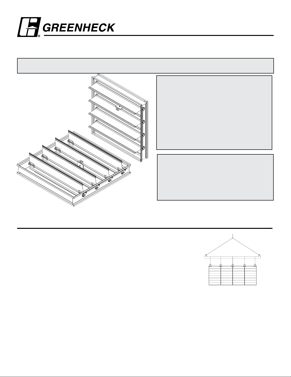
2) Lift or handle damper using sleeve or frame. Do not lift damper using blades or linkage.
When handling multiple sections assemblies, use sufficient support to evenly lift at each
section mullion (see Figure 1). Do not drag, step on, apply excessive bending, twisting, or
racking.
3) Do not install screws in damper frame that will interfere with damper blades and prevent
them from opening and/or closing.
4) Damper must be installed into duct or opening square and free of twist or other misalignment. Damper must not be
squeezed or stretched into duct or opening. Out of square, racked, twisted or misaligned installations can cause excessive
leakage and/or prevent free operation.
Figure 1- supports for lifting a
multi-section damper
5) Damper must be kept clean, dry and protected from dirt, dust and other foreign materials prior to and after installation.
Examples of such foreign materials include but are not limited to:
a) Drywall/mortar dust
b) Firesafing materials
c) Wall texture
d) Paint overspray
Page 2
Pre-Installation Guidelines continued....
Airflow
Adjustable
Counterweight
Assembly
Airflow
Adjustable
Counterweight
Assembly
Airflow
Adjustable
Counterweight
Assembly
6) Damper should be sufficiently covered as to prevent overspray if wall texturing or spray painting will be performed within 5
feet (1.50m) of the damper.
7) ACCESS: Suitable access must be provided for damper inspection and servicing. Where it is not possible to achieve
sufficient size access, it will be necessary to install a removable section of duct.
Counterweight Adjustment Procedure for BR Models
Dampers are shipped from the factory with frame flange location and flow direction as ordered. Location and size of both
counterbalances (blade edge, adjustable blade weights) are dependent upon flow direction and damper size. The damper must
be mounted square and plumb and must operate freely before any weight adjustments are performed. Contact Greenheck for
required modifications to change flow directions.
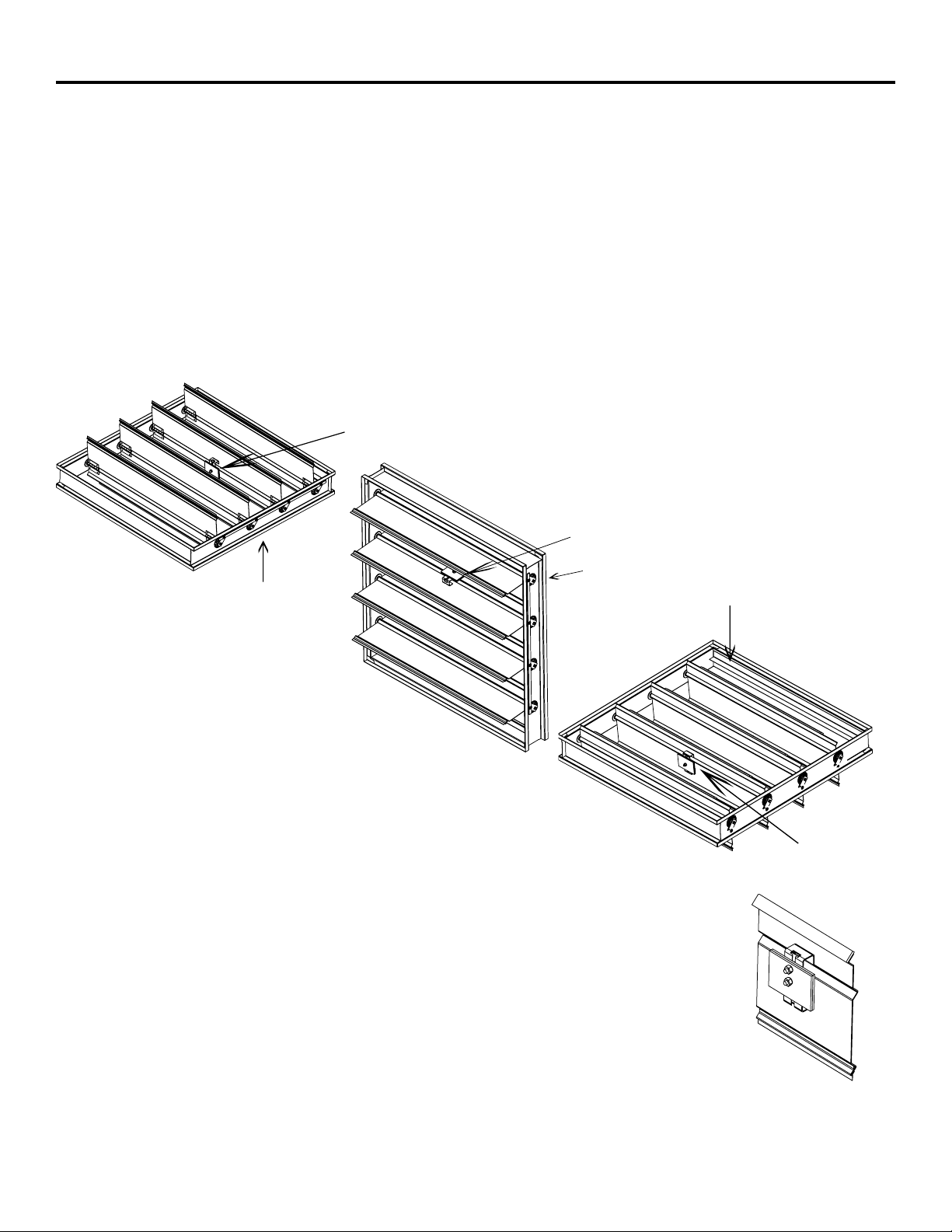
The following instructions should be followed when attempting to adjust counterweights on the BR series damper. Figure 1, 1A, &
1B shows the typical location of the adjustable counterweight assembly. Depending on the size of the damper and specified start
open pressure, the damper may have more than one counterweight assembly.
Figure 1
BR-1x series
Figure 1A
BR-3x series
Figure 1B
BR-4x series
Counterbalance Adjustment for BR-1X Series: Horizontal mount - Vertical Up Airflow
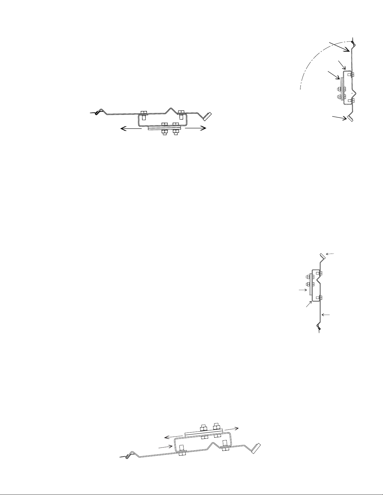
Figures 2 & 3 show the components of a typical adjustable counterweight assembly. BR-1X series
damper with a short height may have a different style blade and a trimmed mounting bracket. The
adjustment procedure is the same for both styles of blades.
The blade edge counterweight (Figure 3) is factory set and not intended for field adjustment. For vertical
up airflow, all adjustments should be made in the adjustable counterweight assembly.
When adjusting the counterbalance weights, you will need to adjust the full open pressure and start
open pressure. Both steps will need to be done.
Adjusting Full Open Pressure and Closing Force
Adjusting the closing force will also affect the full open pressure. Figure 3 shows the blade in the full
open position. Additional weights can be added to increase the closing force. Removal or trimming of
weights will reduce the closing force. After adjustment, verify blades close under no airflow from the full open position. Increase
the closing force if the blades fail to close.
Figure 2 Adjustable
counterweight assembly
Page 3
Counterbalance Adjustment for BR-1X Series: Horizontal mount - Vertical Up Airflow
Counterweight
Adjustment
Bracket
Counterbalance
Weights
Blade Edge
Counterweight
Damper
Blade
Increases Start
Open Pressure
Decreases Start
Open Pressure
Blade Edge
Counterweight
Damper Blade
Counterbalance
Weights
Counterweight
Adjustment bracket
Increases Closing
Force
Decreases Closing
Force
Bottom of
Bracket
cont.......
Adjusting Start Open Pressure
When the blades are in the closed position, the adjustable weights are used for the start open pressure
of the damper. Sliding the weights toward the blade seal will increase the start open pressure and sliding
the weights toward the blade edge counterweight will decrease pressure (Figure 4).
If sliding the weights to the furthest left position (toward the blade seal) does not provide a high enough
start open pressure, additional weights can be added. In this case, the closing force will also increase.
Figure 3 - Adjustable
counterweight assembly
Figure 4: Counterweight adjustment for start open pressure. Blade is shown in
full close position
Dampers are factory adjusted to the start open pressure, based upon your order, for the specified flow direction. Typically, a
minimum of one weight plate will be used to keep blades closed, although only the mounting bracket may be sufficient for small
damper sizes. Consult factory for plate quantity and sizing if an elevated start open pressure is required.
Final Adjustment Check
detail
After adjusting the counterweights, verify that no interference occurs between the counterweights and the adjacent blades. If any
interference, adjust counterweights. Also verify that the damper blades close under no airflow from the full open, 1/2 open, and
1/4 open positions. If blades do not close, adjust weights as required.
Counterbalance Adjustment for BR-3X Series: Vertical mount - Horizontal Airflow
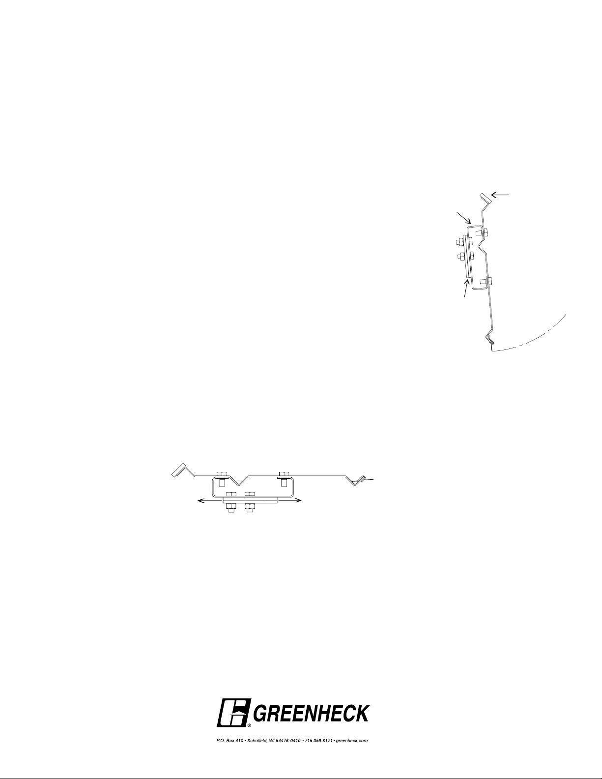
Figure 5 details the components of a typical adjustable counterweight assembly. Dampers with
a short height may have a different style blade and a trimmed mounting bracket. The adjustment
procedure is the same for both styles of blades.
The blade edge counterweight (Figure 5) is factory set and not intended for field adjustment. For
horizontal airflow, all adjustments should be made in the adjustable counterweight assembly.
When adjusting the counterbalance weights, you will need to adjust the full open pressure and
start open pressure. Both steps will need to be done.
Adjusting Start Open Pressure
When the blades are in the closed position (Figure 5), the adjustable weight are used for the
start open pressure of the damper. Additional weights can be added to increase start open pressure and removal or trimming of
weights will reduce start open pressure. After adjustment, verify blades close under no airflow from the 1/4 open position. If the
blades fail to close, additional weight is required.
Adjusting Full Open Pressure and Closing Force
Adjusting the closing force will also affect the full open pressure. Figure 6 shows the blade in the full open position. If blades hang
open or more closing force is desired, slide weights toward the bottom of the bracket (Figure 6). If the blades close too fast or less
closing force is desired, move weights toward the top of the bracket (Figure 6).
Figure 6: Counterweight adjustment in the full open position
Figure 5 - Adjustable
counterweight assembly detail
Page 4
Counterbalance Adjustment for BR-3X Series: Vertical mount - Horizontal Airflow cont.....
Blade Edge
Counterweight
Counterbalance
Weights
Counterweight
Adjustment
Bracket
Blade Edge
Counterweight
Counterweight
Adjustment
Bracket
Increases
Open Pressure
Decreases
Open Pressure
Dampers are factory adjusted to the start open pressure, based upon your order, for the specified flow direction. Typically, a
minimum of one weight plate will be used to keep blades closed, although only the mounting bracket may be sufficient for small
damper sizes. Consult factory for plate quantity and sizing if an elevated start open pressure is required.
Final Adjustment Check
After adjusting the counterweights, verify that no interference occurs between the counterweights and the adjacent blades. If any
interference, adjust counterweights. Also verify that the damper blades close under no airflow from the full open, 1/2 open, and
1/4 open positions. If blades do not close, adjust weights as required.
Counterbalance Adjustment for BR-4X Series: Horizontal mount - Vertical Down Airflow
Figure 7 details the components of a typical adjustable counterweight assembly. Dampers with
a short height may have a different style blade and a trimmed mounting bracket. The adjustment
procedure is the same for both styles of blades.
The blade edge counterweight (Figure 7) is factory set for the specified start open pressure.
For vertical down airflow, minor adjustments can be made in the adjustable counterweight
assembly. If the desired change is greater than the capability of the adjustable counterweight
assembly, then changes to the blade edge weight would be required. Consult factory for
assistance in adjusting blade edge weight.
When adjusting the counterbalance weights, you will need to adjust the full open pressure and
start open pressure. Both steps will need to be done.
Adjusting Full Open Pressure and Closing Force
Adjusting the closing force will also affect the full open pressure. Figure 7 shows the blade in
the full open position. Additional weights can be added to increase the closing force. Removal
or trimming of weights will reduce the closing force. After adjustment, verify blades close under
no airflow from the full open position. Increase the closing force if the blades fail to close.
Figure 7 - Adjustable counterweight
assembly detail
Adjusting Start Open Pressure
When the blades are in the closed position, the adjustable weights are used for the start open pressure of the damper. Sliding the
weights toward the blade edge counterweight will increase the start open pressure and sliding the weights toward the blade seal
will decrease pressure (Figure 8).
Figure 8: Counterweight adjustment for start open pressure.
Blade is shown in full close position.
If sliding the weights to the furthest left position (toward the blade edge counterweight) does not provide a high enough start
open pressure, additional weight to the blade edge counterweight would be required. Consult factory with desired start open
pressure.
Dampers are factory adjusted to the start open pressure, based upon your order, for the specified flow direction. Typically, a
minimum of one weight plate will be used to keep blades closed, although only the mounting bracket may be sufficient for small
damper sizes. Consult factory if an elevated start open pressure is required.
Final Adjustment Check
After adjusting the counterweights, verify that no interference occurs between the counterweights and the adjacent blades. If any
interference, adjust counterweights. Also verify that the damper blades close under no airflow from the full open, 1/2 open, and
1/4 open positions. If blades do not close, adjust weights as required.
Copyright ©2006 Greenheck Fan Corporation
#469420 BR series IOM Rev 1 August 2006
 Loading...