

Page 1
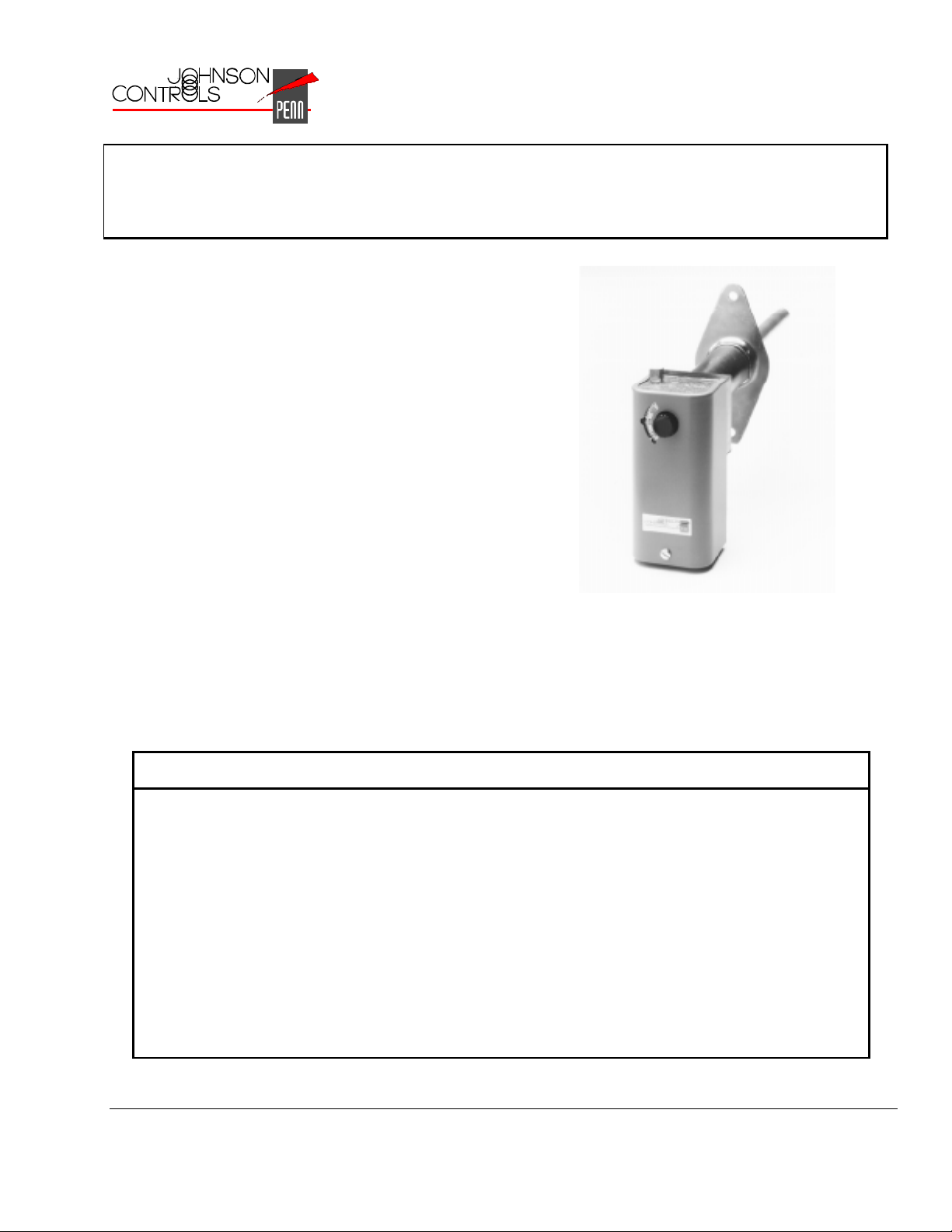
A25 Series Warm Air Control with Manual Reset
The A25 Series Warm Air Control with Manual Reset is
designed to shut down fans, burners, dampers, etc.,
when the temperature of the sensed air becomes
greater than the controller’s setpoint.
When the sensed temperature increases to the
controller’s setpoint, the A25’s switch will open.
Manual reset is required to reclose the electrical circuit.
The A25 may be used as a high limit control in the
supply air duct (or plenum) where a lockout type
control is desired or required by local code.
FANs 125, 121
Product/Technical Bulletin A25
Issue Date 0796
Figure 1: The A25 Series Warm Air Control
with Manual Reset
Features and Benefits
❑
Trip-free Reset Lever Does not allow the reset switch to hold the contacts in a closed (on)
position
❑
Pilot Duty Electrical Rating for
up to 600 Volts Maximum
❑
Enclosed Switch Protects switch contacts from dust
❑
Rod and Tube Sensing
Element
❑
Adjustable Duct
Mounting Flange
❑
Wide Temperature Range Allows the A25 to be used with many applications
Allows direct control of high voltage motor starters
Provides maximum response and allows for a high maximum
sensing element temperature
Controls the depth of sensor insertion into the airstream;
compensates for insulation depth
© 1996 Johnson Controls, Inc.
Part 24-7664-656, Rev.—
Code No. LIT-125118
1
Page 2
pplication Overview
A
A typical application for the A25 Series Warm Air
Control with Manual Reset is to stop the operation of
air conditioning or ventilating fans upon a temperature
rise. Models A25AP and A25CP are Factory Mutual
approved for use as fire protection devices.
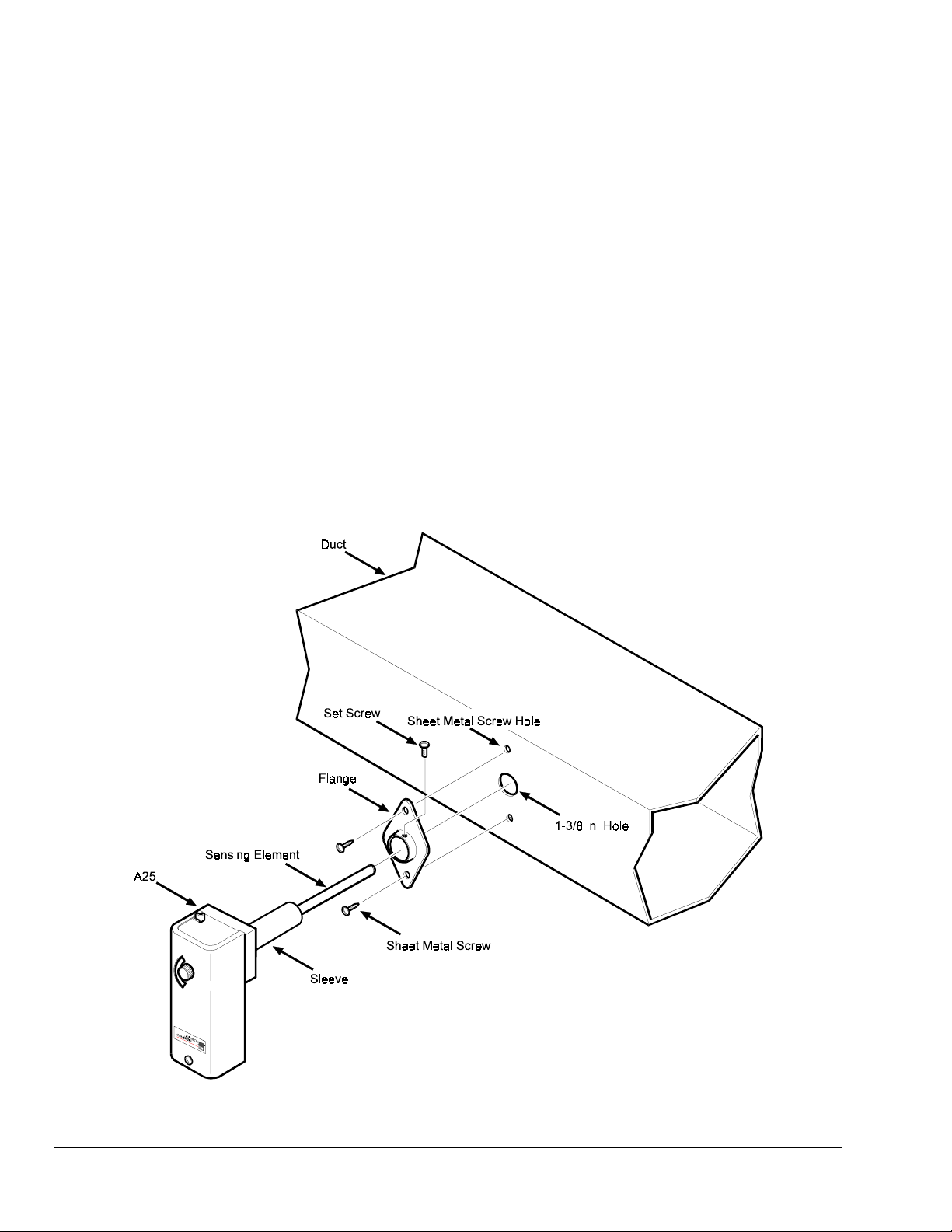
3. Using the flange as a template on the duct, mark
the location for two 1/2 in. (13 mm) No. 10 sheet
metal screws.
4. Punch (or drill) both sheet metal screw holes in the
duct at the marked locations.
5. Secure the flange to the duct with two 1/2 in.
(13 mm) No. 10 sheet metal screws provided.
nstallation
I
1. Select a mounting location for the A25 in the duct
(or plenum). The location must allow the sensing
element to sense the average temperature in the
duct.
2. Drill (or cut) a 1-3/8 in. hole in the duct at the
selected mounting location (refer to Figure 2).
6. Insert the sensing element and sleeve through the
flange installed in Step 5 (and into the duct).
7. Secure the A25 to the flange by screwing the set
screw firmly against the sleeve. Do not
overtorque the set screw.
Note: Insert the sensing element as far as possible
into the air stream without allowing it to contact
any object inside the duct. Provide at least
5-3/4 in. (14 cm) clearance between the
sensor and any other objects inside the duct.
Figure 2: Installing the A25
2 A25 Series Warm Air Control with Manual Reset Product/Technical Bulletin
Page 3
iring
W
WARNING: Shock hazard. To avoid
electrical shock or damage to
equipment, disconnect all power
before making wiring
connections.
If available, follow the instructions for the unit onto
which the A25 will be installed. Make all wiring
connections only with copper conductors and in
accordance with the National Electrical Code and local
regulations. Refer to the label inside the A25’s cover
for the maximum electrical rating.
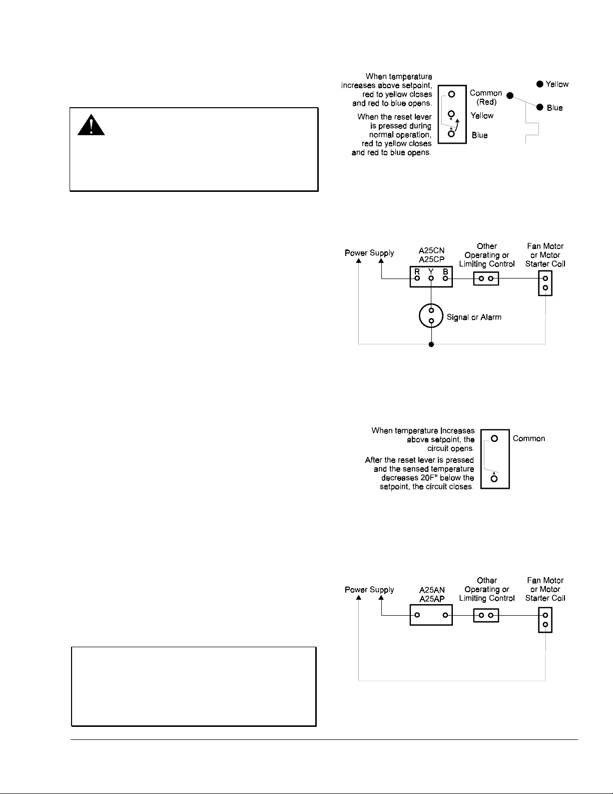
Models A25CN and A25CP
SPDT (Single Pole Double Throw) Units
The wiring terminals on the SPDT (Single Pole
Double Throw) models are color coded:
●
Red is common.
●
The red to yellow circuit closes on temperature
increase.
Figure 3: Terminal Identification for
A25CN and A25CP SPDT Models
Figure 4: Typical Wiring Diagram of
A25CN and A25CP SPDT Models
●
The red to blue circuit opens on temperature
increase.
Refer to Figures 3 and 4 for terminal identification and
typical wiring connections.
When the reset lever is pressed during normal
operation, the trip free contacts are activated, the red
to blue contact opens and the auxiliary red to yellow
contact closes. At this point, the auxiliary system
will activate.
Models A25AN and A25AP
SPST (Single Pole Single Throw) Units
When the temperature increases to above the setpoint,
the circuit opens. When the reset lever is pressed after
the sensed temperature decreases to approximately
20F° (11C°) below the setpoint, the circuit closes.
Refer to Figures 5 and 6 for terminal identification and
typical wiring connections.
IMPORTANT: Only use the terminal screws
furnished with the A25 (8-32 x
1/4 in. binder head). Use of other
screws will void warranty, may
damage switch terminals, and
result in improper connections.
Figure 5: Terminal Identification for
A25AN and A25AP SPST Models
Figure 6: Typical Wiring Diagram for
A25AN and A25AP SPST Models
A25 Series Warm Air Control with Manual Reset Product/Technical Bulletin 3
Page 4

heckout Procedure
C
O
peration
After installing the A25, perform the following
procedures. Observe at least three complete
operating cycles to verify that all components are
functioning properly. If the unit fails to checkout, refer
to the troubleshooting chart (Table 2). Do not attempt
to make adjustments.
Return Air Applications
1. After completing the installation and wiring
procedures, turn on the power to the circuit.
2. Turn the setpoint knob counterclockwise until
the A25 shuts down the system.
The A25 should lockout and the alarm or
signal (if applicable) should activate.
Note: The setpoint at shutdown should equal the
approximate duct air temperature.
3. Turn the setpoint knob clockwise to the
desired setpoint.
Nothing should happen.
4. Press the reset lever.
The system should restart and the alarm or
signal (if applicable) should shut off.
Models A25AN and A25CN
Setpoint Adjustment: Adjust the A25 setpoint by
rotating the setpoint knob (Figure 7). The setpoint
is displayed in the setpoint window.
Test Procedure:
To test (trip) the A25: Raise the temperature
at the sensor above the setpoint or lower the
setpoint below the ambient temperature.
control should lockout (trip).
To reset after test: Lower the temperature at
the sensor to 20F° (11C°) below the setpoint or
raise the setpoint to 20F° (11C°) above the
ambient temperature. Press the reset lever.
The A25 should reset (closing the circuit).
Reset Procedure: Verify that the temperature has
dropped to 20F° (11C°) below setpoint. Press the
reset lever to reset the A25 (closing the circuit).
The
Supply Air Applications
1. After completing the installation and wiring
procedures, turn on the power to the circuit.
2. Raise the supply air temperature to the
setpoint temperature.
Note: The supply air temperature can be raised
by simulating a fan failure or restricting the
return air flow.
3. When the system shuts down, determine the
temperature at the A25 sensing element.
The temperature reading should closely
approximate the A25’s setpoint at which the
system is shut down and (if applicable) the
alarm or signal is activated.
4. Return the system to normal operation by
re-establishing air flow or by restarting the fan.
5. Press the reset lever.
The system should restart and the alarm or
signal (if applicable) should shut off.
Figure 7: Models A25AN and A25CN
4 A25 Series Warm Air Control with Manual Reset Product/Technical Bulletin
Page 5

Models A25AP and A25CP
Setpoint Adjustment: Loosen the cover screw
(Figure 8) and remove the cover. Adjust the
setpoint by rotating the adjusting screw. When
adjusted, re-install the cover. Tighten cover screw.
Test Procedure:
To test (trip) the A25: Raise the temperature
at the sensor above the setpoint or lower the
setpoint below the ambient temperature.
control should lockout (trip).
To reset after test: Lower the temperature at
the sensor to 20F° (11C°) below the setpoint or
raise the setpoint to 20F° (11C°) above the
ambient temperature. Press the reset lever.
The A25 should reset (closing the circuit).
Reset Procedure: Verify that the temperature has
dropped 20F° (11C°) below setpoint. Press the
reset lever to reset the A25 (closing the circuit).
imensions
D
The
Figure 8: Models A25AP and A25CP
Figure 9: A25 Dimensions, in./mm
A25 Series Warm Air Control with Manual Reset Product/Technical Bulletin 5
Page 6

epairs and Replacement
R
Do not make field repairs. For a replacement control,
contact your nearest Johnson Controls representative.
Table 1: Ordering Information
Item Product Code
Number
A25 Series Warm Air
Control with Manual Reset
roubleshooting
T
A25AN-1
A25AP-1
A25CN-1
A25CP-1
Table 2: Troubleshooting Chart
Symptom Problem Solution
The A25 is not sensing properly.
The system does not operate.
A25 does not lockout upon a
temperature rise beyond the setpoint.
The A25 does not sense the correct air
temperature.
A25 will not reset.
Product
Description
SPST, opens on temperature rise, setpoint knob adjustment.
SPST, opens on temperature rise, concealed screwdriver adjustment,
Factory Mutual approved.
SPDT, setpoint knob adjustment.
SPDT, concealed screwdriver adjustment, Factory Mutual approved.
The sensing element may not be
extended into the airstream or the
sensing element is contacting an object
inside of the duct (or plenum).
Incorrect switch connections or improper
wiring.
Damaged sensor.
The A25 is tripped.
The A25 is defective. Replace the A25.
The A25 is defective. Replace the A25.
The temperature in the duct (or plenum)
is not 20F° (11C°) below the setpoint.
Insert the sensing element as far as
possible into the airstream without
allowing it to contact any object inside the
duct (or plenum).
Ensure that the wiring connections follow
the wiring diagrams in the
Check connections.
Replace the A25.
Reset the A25.
Check system for overheating or fire.
Wiring
section.
6 A25 Series Warm Air Control with Manual Reset Product/Technical Bulletin
Page 7

Notes
A25 Series Warm Air Control with Manual Reset Product/Technical Bulletin 7
Page 8

pecifications
S
Product
Range
Electrical Ratings Volts, AC 120 VAC 208 VAC 240 VAC 277 VAC
Ambient Temperature
(Maximum)
Conduit Opening
Switch
Cover Finish
High Limit Dial Stop
Material
Mounting
Reset
Sensing Element
Shipping Weight
Wiring Connections
Agency Listing
* FLA = Full Load Amps; LRA = Locked Rotor Amps. Values are equivalent to a 1 HP motor rating in accordance with UL353.
The performance specifications are nominal and conform to acceptable industry standards. For application at conditions beyond these specifications,
consult the local Johnson Controls office. Johnson Controls, Inc. shall not be liable for damages resulting from misapplication or misuse of its products.
A25AN-1 SPST, opens on temperature rise, setpoint knob adjustment.
A25AP-1 SPST, opens on temperature rise, concealed screwdriver adjustment,
Factory Mutual approved.
A25CN-1 SPDT, setpoint knob adjustment.
A25CP-1 SPDT, concealed screwdriver adjustment, Factory Mutual approved.
25 to 215°F (-4 to 102°C)
Motor FLA*
Motor LRA*
Noninductive A
Case 104°F (40°C)
Element 300°F (149°C)
7/8 in. (22 mm) diameter hole for 1/2 in. conduit
Snap-acting contacts in dust protected enclosure
Gray baked enamel
125°F
Case 0.063 in. (1.6 mm) galvanized steel
Cover 0.025 in. (0.64 mm) cold rolled steel
Flange for flat surface
Positive, trip-free reset mechanism (manual reset 2 operation). Control can be reset when
the temperature drops 20F° (11C°) below the dial setting.
Bi-metal rod and tube construction
Individual pack 1.8 lb. (0.8 kg)
Overpack of 12 units 23 lb. (10.4 kg)
Screw-type terminals
UL Recognized: File MP640, Guide MBPR
CSA Certified: File LR948, Class 4813 02
Factory Mutual Approved (Models A25AP and A25CP only): Class 3545
16 9.2 8 96 55.2 48 16 16 16 16
Pilot Duty: 125 VA at 24/600 VAC
Controls Group
507 E. Michigan Street
P.O. Box 423
Milwaukee, WI 53201 Printed in U.S.A
8 A25 Series Warm Air Control with Manual Reset Product/Technical Bulletin
 Loading...