

Page 1
Submittal Sheet
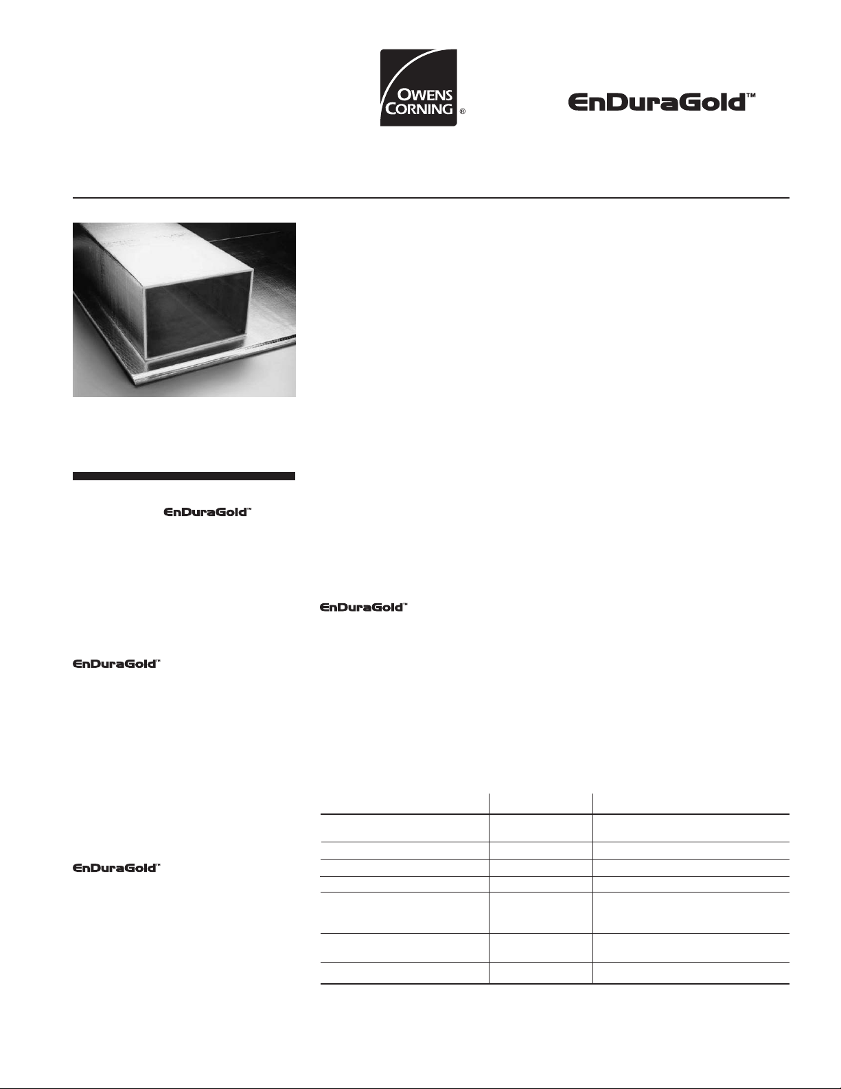
Fiber Glass Duct Board
❏
TYPE 475, 1" (25mm)
❏
TYPE 800, 1" (25mm)
❏
TYPE 800, 1
❏
TYPE 1400, 2" (51mm)
Description
1
/
2" (38mm)
Owens Corning
Fiber Glass Duct Board is a rigid, resin
bonded fibrous glass board with a tough,
damage-resistant, flame retardant,
reinforced aluminum foil (FRK) facing.
When fabricated into duct systems, it
combines excellent thermal and
acoustical insulating properties with
substantially airtight transmission of air
when all joints are sealed with UL 181A
listed closures.
Fiber Glass Duct Board
features a durable air stream surface that
isolates the glass fiber substrate from the
airstream and inhibits penetration of the
insulation by dirt, dust and other
pollutants. This durable air stream surface
makes it easy to clean the duct system
using methods and equipment described
in North American Insulation
Manufacturers Association (NAIMA)
Publication AH122, Cleaning Fibrous
Glass Insulated Duct Systems,
Recommended Practice.
Uses
Fiber Glass Duct Board
may be used to fabricate components for
indoor commercial and residential
heating, ventilating and air conditioning
duct systems operating at static pressures
to ±2 in. w.g. (500 Pa), internal air
temperatures 40°F (4°C) to 250°F
(121°C), and air velocities to 6,000 fpm
(30.5 m/s). Straight duct sections, elbows,
tees, offsets and other system elements
can quickly and easily be fabricated and
assembled into a complete air
transmission system using these
lightweight, thermally efficient boards.
Features and Benefits
Bacterial and Fungal Growth Resistance
A durable air stream surface includes an
EPA registered biocide that protects the
air stream surface from microbial growth
and meets requirements of ASTM C 1338,
ASTM G 21 (fungi test) and ASTM G 22
(bacteria test).
Tips to Avoid Mold Growth in Ducts
Mold in duct systems occurs when
moisture comes into contact with dirt
or dust collected on the duct system
surfaces. Proper filters will minimize
the collection of dust and dirt, but
care needs to be exercised to prevent
water formation in the duct. A
properly sized and operated air
conditioning unit will minimize the
likelihood of water formation. The
system must be maintained and
operated to insure that sufficient
dehumidification is occurring and that
filters are installed and changed as
recommended by the equipment
manufacturer.
Assured Thermal Performance
R-values as published for
Fiber Glass Duct Board
are superior to those of compressible
insulation of equal thickness. Factory
control of thickness assures that installed
R-values will be as published for the
product.
Acoustically Efficient
Duct systems built with these boards
absorb fan and air turbulence noise;
reduce popping noises caused by
expansion, contraction and vibration.
Fabrication and installation are quieter.
Single Contractor Accountability
Thermal/acoustical insulation board plus
jacket forms a single component duct
system, thus reducing inspection time.
Lightweight
These lightweight boards are easier to
transport and handle than insulated sheet
metal ducts. They reduce the load
imposed on the structure by the duct
system.
Virtually Eliminates Air Leakage
Closures with UL 181A listed pressuresensitive tape, heat-activated tape, or
glass fabric and mastic virtually eliminate
air leakage. This saves energy and
removes the need for system overdesign.
Code Compliance
Meets the following model codes and
most other applicable codes: NFPA
90A/90B, ICC International Mechanical
Code, SBCCI, ICBO, BOCA, CABO, Corps
of Engineers Guide Spec., NYC MEA
#186-69.
Supported by Industry Standards
Proper fabrication and installation guidelines help ensure long-term performance
of the system. These standards,
developed by NAIMA and SMACNA, lead
to clearer understanding between
specifier and contractor.
Physical Property Data
Property Test Method Value
Maximum operating temperature limits UL 181 Internal: 250°F (121°C)
Maximum air velocity UL 181 Erosion Test 6,000 fpm (30.5 m/s)
Static pressure limit UL 181 ±2 in. w.g. (500 Pa)
Water vapor sorption ASTM C 1104 <3% by weight at 120°F (49°C), 95% R.H.
Mold growth UL 181 Meets requirements
Fungi resistance ASTM G 21 Meets requirements
Bacteria resistance ASTM G 22 Meets requirements
Surface burning characteristics UL 723* Flame spread 25*
Fire retardancy UL 181 Flame penetration: 30 min.
* The surface burning characteristics of these products have been determined in accordance with UL 723. This standard should be
used to measure and describe the properties of materials, products or assemblies in response to heat and flame under controlled
laboratory conditions and should not be used to describe or appraise the fire hazard or fire risk of materials, products or assemblies
under actual fire conditions. However, results of this test may be used as elements of a fire risk assessment which takes into account
all of the factors which are pertinent to an assessment of the fire hazard of a particular end use. Values are reported to the nearest
5 rating.
External: 150°F (66°C)
Smoke developed 50
Page 2
Fiber Glass Duct Board
Availability
Fiber Glass Duct Board
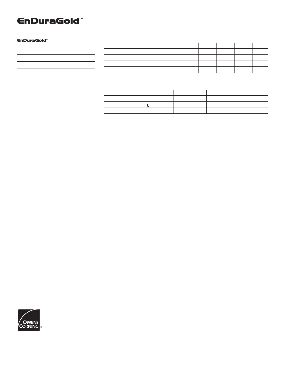
Acoustical Performance
Sound absorption coefficients at octave band center frequencies, Hz.
is available in the following forms:
TYPE 475, 1" (25mm) thick
TYPE 800, 1" (25mm) thick
1
/
TYPE 800, 1
TYPE 1400, 2" (51mm) thick
Type designates board stiffness defined by flexural rigidity.
Type selection depends on duct size, pressure and reinforcement
schedule. The 1
superior thermal value.
2
" (38mm) thick
1
/
2" (38mm) and 2" (51mm) thickness provides
UL Class 1 Air Duct
National Fire Protection Association
Standards NFPA 90A and 90B for air
conditioning and ventilating systems
require air ducts to be Class 0 or 1. The
tests set stringent requirements on fire
safety as well as ruggedness. To meet
Class 1 air duct requirements, the system
must withstand UL 181 tests such as
rupture, pressure loss, impact, collapse,
puncture, static load and fire retardancy
(30 minute flame penetration test). Also,
to qualify as a Class 1 Air Duct System,
the following UL 723 fire testing
requirements must be met: Flame spread,
25; Smoke developed, 50.
Limitations
Fiber glass ducts should not be used in
the following applications:
A. Kitchen or fume exhaust ducts, or to
convey solids or corrosive gases;
B. In concrete or buried below grade;
C. Outdoors;
D. As casings and/or housings of built-up
equipment;
E. Immediately adjacent to high
temperature electric heating coils without
radiation protection;
F. For vertical risers in air duct systems
serving more than two stories in height;
G.With coal or wood fueled equipment,
or with equipment of any type which
does not include automatic maximum
temperature controls;
H. In variable air volume systems on the
high pressure side unless reinforced to
withstand the full fan pressure;
I. As penetrations in construction where
fire dampers are required, unless the fire
damper is installed in a sheet metal sleeve
extending through the fire wall; or
Type 475, 1" (25mm) 0.08 0.19 0.69 0.94 0.99 0.98 0.70
Type 800, 1" (25mm) 0.08 0.19 0.69 0.94 0.99 0.98 0.70
1
Type 800, 1
Type 1400, 2" (51mm) 0.14 0.72 1.15 1.12 1.06 1.07 1.00
These data were collected using a limited sample size and are not absolute values. Therefore, reasonable tolerances must be
applied. Tests were conducted in accordance with ASTM C 423, Mounting A (material placed against a solid backing).
/
Thermal Performance, at 75°F (24°C) Mean Temperature
R-value, hr•ft2•°F/Btu (RSI, m2•°C/W) 4.3 (0.76) 6.5 (1.15) 8.7 (1.53)
k-value, Btu•in/hr•ft
C-value, Btu/hr•ft
Mean temperature is the average of two temperatures: that of the air inside the duct and that of the ambient air outside it.
Note: Specified design thickness should be adequate to prevent exterior surface condensation.
J. When the duct system is located in
non-conditioned space and is used for
cooling only (when heating is from
another source), unless all registers which
would allow moist air into the duct system
are vapor sealed during the heating
season to prevent condensation from
forming inside the duct.
Application Recommendations
Fabrication and installation of fiber glass
Duct Systems shall be in accordance with
the UL listing and shall conform to Owens
Corning’s published methods and/or latest
editions of NAIMA (North American
Insulation Manufacturers Association)
Fibrous Glass Duct Construction
Standards or SMACNA (Sheet Metal
and Air Conditioning Contractors
National Association) Fibrous Glass
Duct Construction Standards. One of
the following closure methods must be
employed to meet the requirements of
UL 181. USE OF A NON-LISTED
CLOSURE SYSTEM VOIDS THE UL
CLASS 1 AIR DUCT RATING.
1. Pressure-Sensitive Tape
Any tape listed and labeled under
UL 181A, Part I (P).
a. All longitudinal and circumferential
joints must be stapled with outward
1
flaring
/
2
(50mm) (approx.) O.C.
b. Wipe surface where tape is to be
applied to field joints with clean cloth.
If surface has grease or oil, saturate
cloth with approved solvent. Refer to
tape manufacturer’s recommendations.
c. Center tape over edge of stapling
flap and rub firmly in place
immediately after application, using
a squeegee or similar tool.
d. A heat sealing iron must be used
to assure a good bond when installed
OWENS CORNING WORLD HEADQUARTERS
ONE OWENS CORNING PARKWAY
TOLEDO, OHIO, USA 43659
1-800-GET-PINK
www.owenscorning.com
EnDuraGold™ is a trademark of Owens Corning.
Pub. No. 57577 Printed in U.S.A., November 2002 Copyright © 2002 Owens Corning
below 50°F (10°C).
e. Tape should not be applied to
surface of duct board when
temperature is below 32°F (0°C)
due to the possibility of entrapping
125 250 500 1000 2000 4000 NRC
2" (38mm) 0.12 0.33 0.92 1.04 1.03 1.02 0.85
1
1" (25mm) 1
2
•°F ( , W/m•°C) 0.23 (0.033) 0.23 (0.033) 0.23 (0.033)
2
•°F (W/m2•°C) 0.23 (1.32) 0.16 (0.87) 0.12 (0.65)
/
2" (38mm) 2" (51mm)
ice crystals which will cause tape
to loosen upon melting. Heat surface
first to drive off moisture.
2. Heat-Activated Tape
Any tape listed and labeled under
UL 181A,Part II (H).
a. All longitudinal and circumferential
joints must be stapled with outward
1
flaring
/
"(13mm) (min.) staples, 2"
2
(50mm) (approx.) O.C.
b. Wipe surface where tape is to be
applied with clean cloth. If surface
has grease or oil, saturate cloth with
approved solvent. Refer to tape
manufacturer’s recommendations.
c. Center tape over joint and seal
down tape end with 500°F (260°C)
iron. Do not use heat gun; heat and
pressure are both required to effect
a seal.
d. Press down entire length of tape
to hold in place using a smearing
action to get good bond. Colored
dots on tape surface darken when
satisfactory bonding temperature
is reached.
e. Staples may be omitted when
automatic closure machines such
as Glass Master Closemasters are
used. Iron temperature must be set
at 650°F (343°C) minimum.
" (13mm) (min.) staples, 2"
Continuous production may require
periodic pauses to allow sealing iron
to recover to 650°F (343°C).
f. Allow joint to cool before
stressing.
3. Mastic and Glass Fabric
Any mastic and glass fabric closure
system listed and labeled under UL
181, Part III (M).
a. All longitudinal and circumferential
joints must be stapled with outward
1
flaring
/
"(13mm) (min.) staples, 2"
2
(50mm) (approx.) O.C.
b. Brush mastic onto joint and embed
glass fabric in mastic.
c. Brush second coat of mastic over
fabric until completely filled.
d. Allow joints to dry in accordance
with mastic manufacturer’s
recommendation before pressurizing
system.
 Loading...