

Page 1
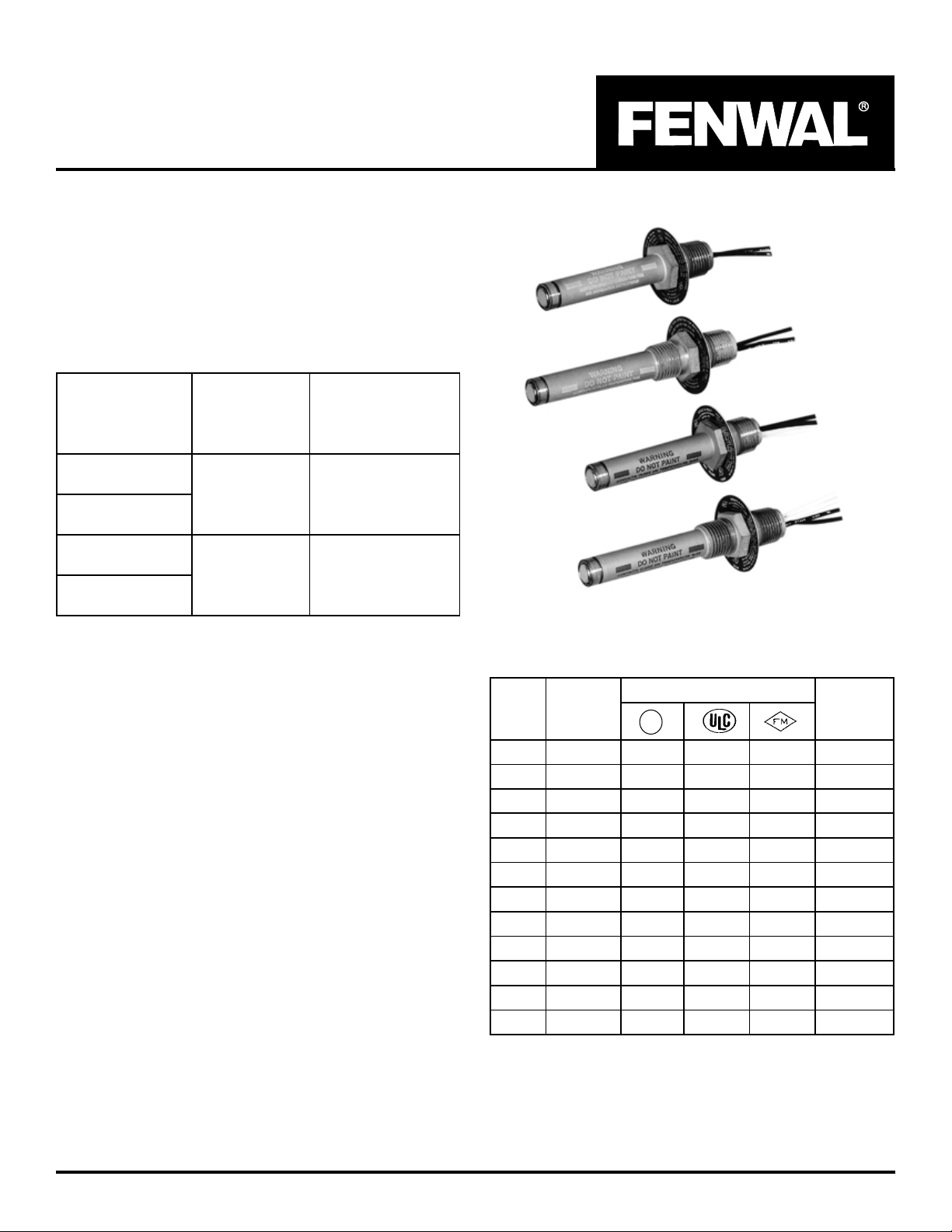
Series 27100, 28000
Vertical DETECT-A-FIRE® Units
Installation Instructions
12.01.D
DESCRIPTION
DETECT-A-FIRE¨ thermal detectors are UL Listed, UL of
Canada available upon request, and FM Approved detection and release devices used with fire detection systems to
activate alarms and actuate extinguishing systems. This Rate
Compensated device combines the best features of both
fixed temperature and rate-of-rise detectors.
ELECTRICAL RA TING
tcatnoC
rebmuNledoM
nonoitarepO
erutarepmeT
esiR
*gnitaRlacirtcelE
)ylnOevitsiseR(
Effective: August 1999
02172
02082
12172
12082
*Although incandescent lamps are considered resistive, their inrush current is 10 - 15 times their steady current. Do not exceed ratings.
snepO
o
054(
)xaMF
sesolC
spmA0.5
spmA5.0
spmA0.5
spmA5.0
spmA0.2
spmA0.1
CAV521
CDV521
CAV521
CDV521
CDV42
CDV84
LOCATION
DETECT-A-FIRE® Units are precision temperature sensors.
They must be mounted in an area (normally a ceiling) so
that:
1. The detector spacing complies with both system requirements and requirements of the agency having local jurisdiction.
2. The thermal air path to the shell is not obstructed.
Spacing per UL, FM, and UL of Canada is shown in T able 1.
Distances given are for between units on smooth ceilings.
Distances from partitions or walls are half that shown. To
assure that all spacing requirements are met, consult the
authority having local jurisdiction.
MOUNTING
Detect-A-Fire units are not position sensitive. Horizontal and
vertical detectors refer to the most common mounting configuration for that unit. However, each type can be mounted
either horizontally or vertically depending on the application
and installation requirements.
Table 1.
o
F
0418-/7+050552kcalB
0618-/7+525252kcalB
0918-/7+050552etihW
0128-/7+520552etihW
5228-/7+520552etihW
57201±520552eulB
52301±050552deR
06301±520552deR
05451±520552neerG
00551±050552egnarO
00602±A/N0552egnarO
52752±A/N0552egnarO
o
gnitteS
F
ecnareloT
U
®
L
)teefni(SGNICAPS
roloC
gnidoC
Note: For clean agents and CO2 suppression systems,
ceiling spacing 20 ft. (6.1 meters) apart unless otherwise specified.
Not all units are suitable for all hazard location applications.
Refer to Table 2 and markings on the detector for hazardous location suitability .
1
Page 2
suodrazaH
noitacoL
spuorG,*IssalC
;DdnaC,B,A
spuorG,*IIssalC
GdnaF,E
spuorG,*IssalC
;DdnaC,B
spuorG,*IIssalC
GdnaF,E
*Division 1 and 2.
INSTALLATION
Table 2.
ledoM
rbmuN
3-02082
5-12082
0-02172
0-12172
0-12082
roFderiuqeRgnittiF
sgnitsiLCLU,LU
lavorppAMFdna
22-02172
02-12172
aotrotcetedtnuoM
nignittifdetsil-ylbatius
htiwecnadroca
edoCcirtcelElanoitaN
ytirohtualacolro/dna
.noitcidsirujgnivah
Series 28000 units are similar to Series 27100 units except
they have two 1/2-14 NPT threads for mounting.
The unit may be mounted as described above or may be
threaded into a 1/2-14 NPT tapped hole in the vessel wall or
threaded into a coupling brazed or welded to the vessel wall.
FIELD WIRING REQUIREMENT
Field wiring must be capable of withstanding the maximum
anticipated ambient temperature in the application.
FUNCTIONAL TEST
When used with automatic fire extinguishing systems first
disconnect the initiator/solenoid leads from the panel and
connect a 24 VDC bulb to initiator terminals in the control
unit. Heat the D-A-F units with a heat lamp or other convenient source. When the bulb in the control unit changes state,
remove heat source and allow D-A-F unit to cool. Reset control unit. Test lamp must change state and stay changed
after system is reset. Do not reconnect initiator/solenoid leads
until all D-A-F units have cooled below set point as indicated
by test lamp. When D-A-F units are used in other types of
systems, disconnect them from the system, connect a 24
VDC lamp and power source in series with the D-A-F units
and test with heat source as above. Make sure that contacts
have reset to normal condition before reconnecting to system circuit.
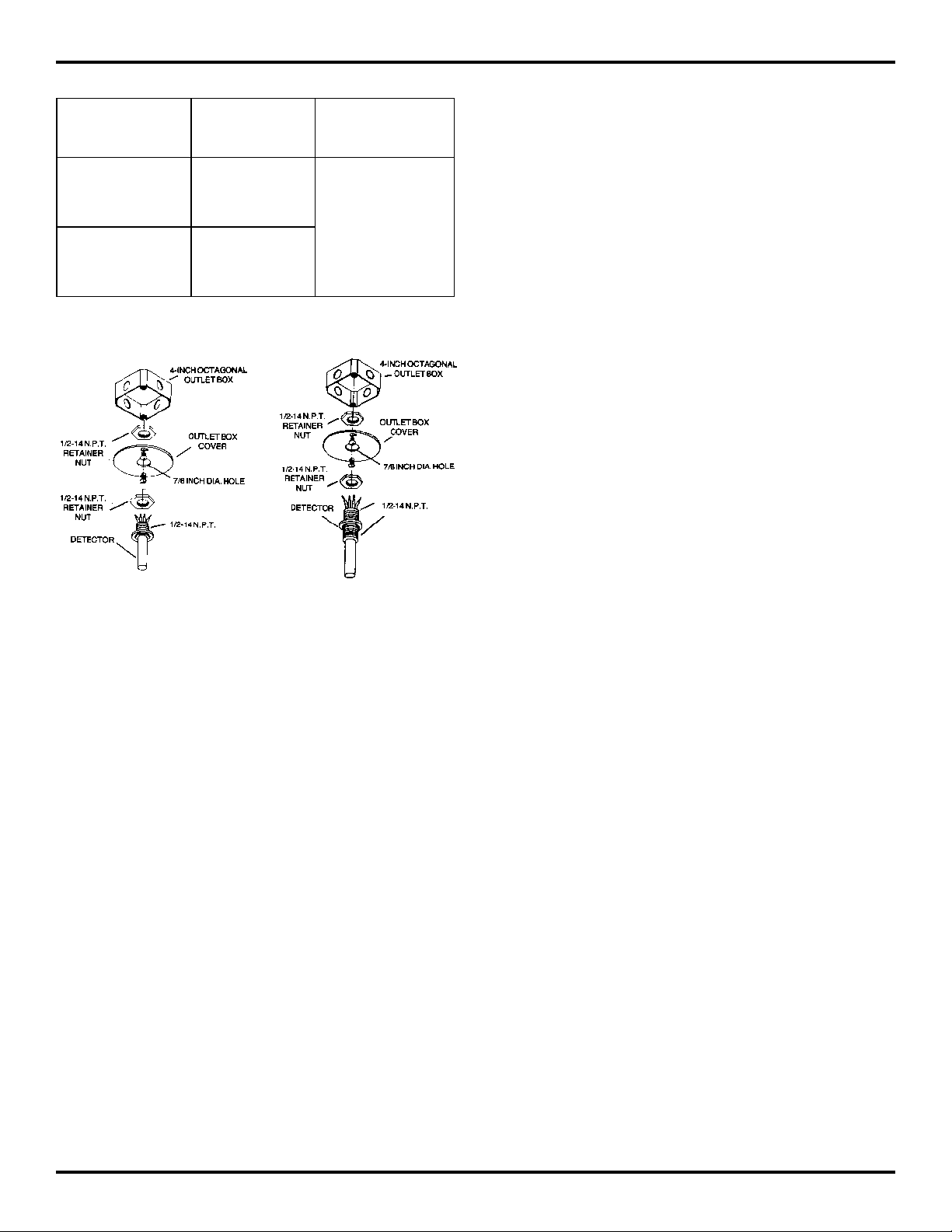
Figure 1
Figure 2
1. Kidde-Fenwal recommends that standard 4-inch octagonal outlet boxes be used to mount detectors.
2. Attach detector to outlet box cover through a 0.875 inch
diameter hole and using two 1/2-14 NPT retainer nuts
as indicated.
3. Connect system wiring to detector per Figure 3 and applicable electrical codes.
4. Ordinary Locations: The DETECT-A-FIRE Units are
to be installed in grounded metallic junction boxes only .
They are to be secured to the boxes using two lock
nuts, one on either side of the mounting plate. DETECTA-FIRE Units are not to be installed in non-metallic junction boxes.
5. Hazardous Locations: For Class I, Division 1 and 2
locations, install the DETECT-A-FIRE Unit in a listed
explosion-proof enclosure with a minimum thread engagement of five full turns. No non-conductive material
is to be placed on the threaded joint of the DETECT-AFIRE Unit or in the listed explosion-proof enclosure.
For Division 2 locations, assure that a protective ground
terminal is provided in the listed explosion-proof enclosure when flexible metal conduit is used.
6. Do not exceed a maximum torque without thread lubricant of 20 foot-pounds (27.1 Newton Meters).
2
Page 3

WARNING
!
1. In order to function properly, the sensing shell of the unit must remain free from paint, grease, oil, etc. Should such a
build up occur, do not, under any circumstances, attempt to remove it. Replace the unit.
2. Detectors mounted in an area subject to physical abuse or damage, other than above, must be suitably protected
without obstructing the thermal air path to the unit.
3. Do not install the unit where the shell would be physically damaged by sand, grain, rocks, etc.
4. Do not overtorque the unit when installing.
5. Any detector that has been abused or damaged must be replaced.
6. Consult the factory for special precautions necessary for outdoor use or moist environments.
ANY OF THE ABOVE COULD CHANGE THE FACTORY TEMPERATURE SETTING, WHICH MAY RESULT IN PROPERTY DAMAGE AND/ OR PERSONAL INJURY OR DEATH.
IT IS POSSIBLE FOR A UNIT TO HAVE BEEN ABUSED OR DAMAGED AND NOT DISPLA Y ANY OUTWARD INDICATION OF THE DAMAGE. ALL UNITS SHOULD BE TESTED PERIODICALL Y IN ACCORDANCE WITH NA TIONAL FIRE
PROTECTION ASSOCIATION REQUIREMENTS (72E) OR THE AGENCY HAVING LOCAL JURISDICTION.
Typical Fire Alarm System Method
Typical Security System Method
Figure 3. System Wiring
These instructions do not purport to cover all the details or variations in the equipment described, nor do they provide for every possible
contingency to be met in connection with installation, operation and maintenance. All specifications subject to change without notice. Should
further information be desired or should particular problems arise which are not covered sufficiently for the purchaser’s purpose, the matter
should be referred to KIDDE-FENWAL, Inc., Ashland, Massachusetts.
3
Page 4

KIDDE-FENWAL, INC.
400 MAIN STREET,ASHLAND, MA 01721
TEL: (508) 881-2000 FAX: (508) 881-8920
www.fenwalfire.com
R
Protection Systems
This literature is provided for informational purposes only. KIDDE-FENWAL,INC. assumes no
responsibility for the product's suitability for a particular application. The product must be properly applied to work correctly.
If you need more information on this product, or if you have a particular problem or question,
R
contact KIDDE-FENWAL INC., Ashland, MA 01721. Telephone: (508) 881-2000
12.01.D 8/99 ©1999 Kidde-Fenwal, Inc. Printed in U.S.A. CP
 Loading...