

Page 1
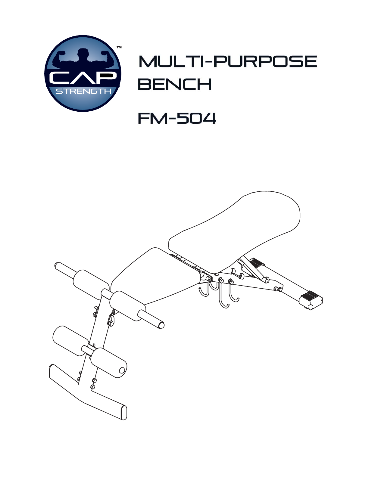
Assembly Manual
Page 2
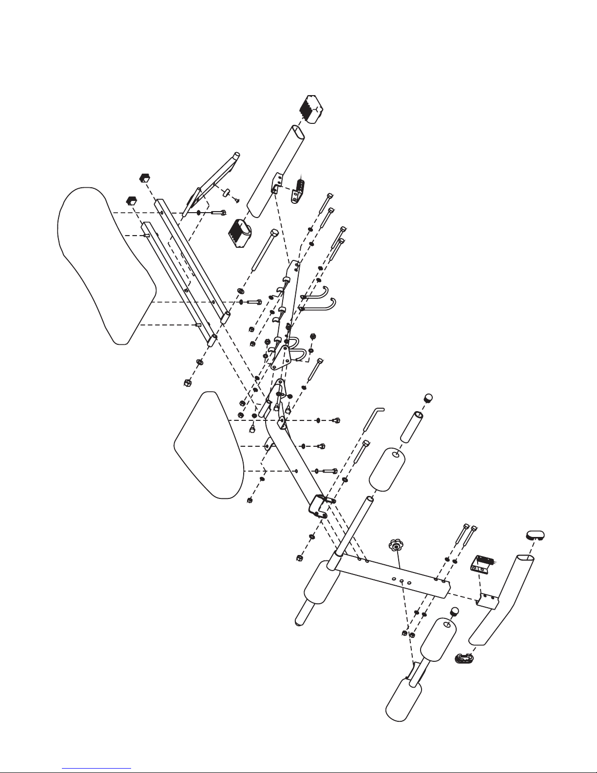
EXPLODED DIAGRAM
1
2
3
4
5
6
7
8
9
10
11
12
13
14
15
16
15
17
18
19
19
20
20
21
21
21
22
22
23
24
25
28
28
26
29
29
27
30
30
30
30
23
30
27
30
30
30
30
30
27
30
30
30
27
30
30
30
27
30
27
31
32
32
33
33
34
34
35
35
36
36
37
38
Page 3
PART LIST
No. Part No. Description Qty.
Pre.-assembled
No. Part No. Description Qty.
Pre.-assembled
1 PFM504-01 Center Support Frame 1 No 20 PFM504-20 M8 x 80mm Bolts 4 No
2 PFM504-02 Back Support Frame 1 No 21 PFM504-21 M8 x 45mm Bolts 5 No
3 PFM504-03 Front Vertical Frame 1 No 22 PFM504-22 M8 x 20mm Bolts 3 No
4 PFM504-04 Front Stabilizer 1 No 23 PFM504-23 M8 x 15mm Bolts 2 No
5 PFM504-05 Rear Stabilizer 1 No 24 PFM2240-23 M6 x 15mm Screw 1 No
6 PFM504-06 Backrest Supports 2 No 25 PRK3E-04 M12 Nylon Locknut
1No
7 PFM504-07 Incline Support 1 No 26 PFMS80-27 M10 Nylon Locknut 1 No
8 PFM504-08 Foam Tube 1 No 27 PFMS80-16 M8 Nylon Locknuts 10 No
9 PFM504-09 Cross Tube 1 No 28 PRK3E-05 M12 Washers 2 No
10 PFM504-10 Long Dumbbell Pothooks 2 No 29 PFMS80-28 M10 Washers 2 No
11 PFM504-11 Short Dumbbell Pothooks 2 No 30 PFMS80-15 M8 Washers 27 No
12 PFM504-12 L-shaped Brackets 2 No 31 PFM504-24 L-shaped Lock Pin 1 No
13 PFM504-13 Seat 1 No 32 PFMG3007-01 30x70mm Rubber End Caps 2 No
14 PFM504-14 Backrest Board 1 No 33 PFMG3251-22 30x70mm Inner C aps 2 No
15 PFM504-15 Foam Rolls 4 No 34 PFM504-25 U-shaped Sleeves 2 No
16 PFM504-16 Foam Grips 2 No 35 PFM2240-32 25mm Square Inner Caps 2 Yes
17 PFM504-17 M12 x 180mm Bolt 1 No 36 PFM504-26 25mm Round Inner Caps 4 No
18 PFM504-18 M10 x 90mm Bolt 1 No 37 PFM504-27 Rubber Bumper 1 Yes
19 PFM504-19 M8 x 90mm Bolts 3 No 38 P F MH1001-36 Knob 1 No
Page 4
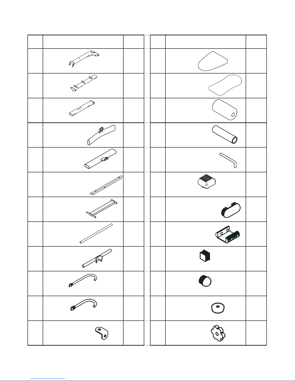
NO. DRAWING Q`TY NO. DRAWING Q`TY
1
Center Support Frame
113
Seat
1
2
Back Support Frame
114
Backrest Board
1
3
Front Vertical Frame
115
Foam Rolls
4
4
Front Stabilizer
116
Foam Grips
2
5
Rear Stabilizer
131
L-shaped Lock Pin
1
6
Backrest Supports
232
30x70mm Rubber End Caps
2
7
Incline Support
133
30x70mm Inner C aps
2
8
Foam Tube
134
U-shaped Sleeves
2
9
Cross Tube
135
25mm Square Inner Caps
2
10
Long Dumbbell Pothooks
236
25mm Round Inner Caps
4
11
Short Dumbbell Pothooks
237
Rubber Bumper
1
12
L-shaped Brackets
238
Knob
1
Page 5
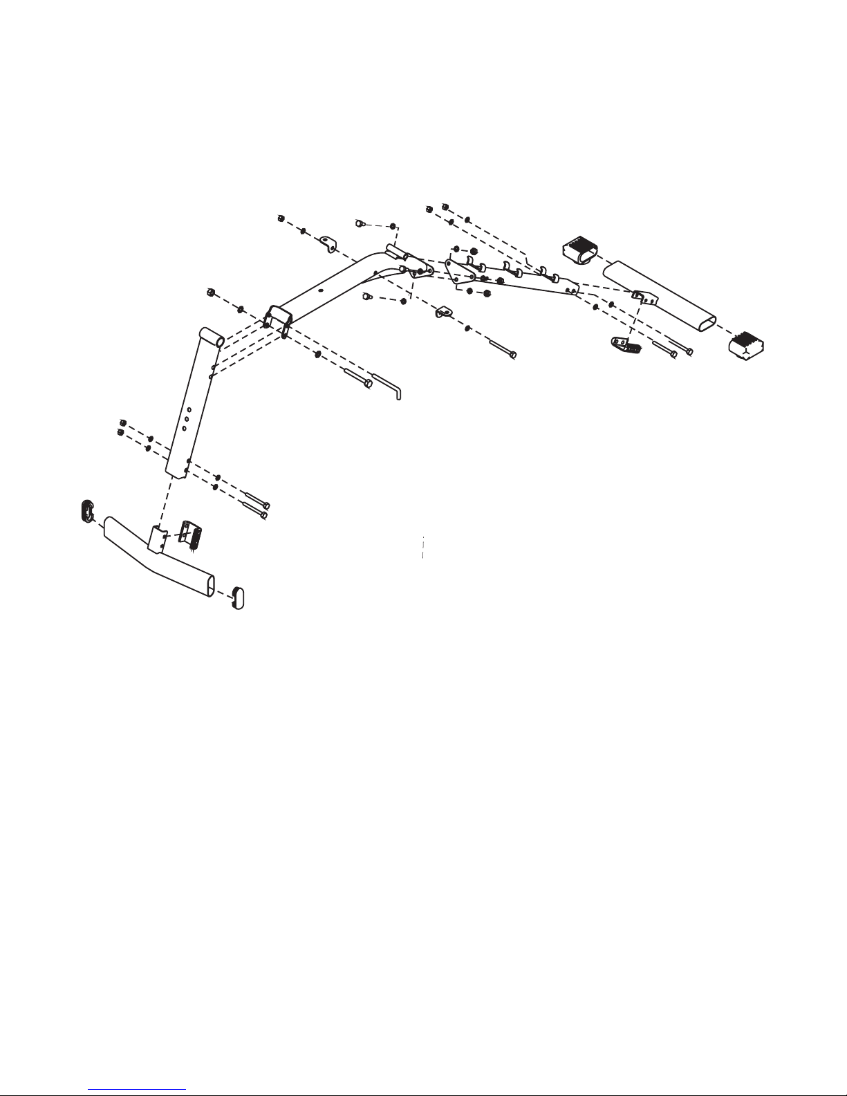
ASSEMBLY INSTRUCTION:
STEP 1
4
5
33
33
34
3
20
30
27
30
18
29
29
26
31
1
2
19
30
27
30
12
12
22
22
30
30
30
30
27
27
27
30
20
30
34
32
32
A.) Push two Inner Caps (#33) into the Front Stabilizer (#4). Push two Rubber End
Caps (#32) into the Rear Stabilizer (#5).
B.) Attach a U-shaped Sleeve (#34) onto the bracket on the Front Stabilizer (#4).
Make sure the opening on the Sleeve is facing towards the front. Attach the
Front Stabilizer to the Front Vertical Frame (#3). Secure it with two M8 x 80mm
Bolts (#20), four M 8 Washers (#30), and two M8 Nylon Locknuts (#27).
C.) Attach one U-shaped Sleeve (#34) to the bracket on the Rear Stabilizer (#5).
Attach the Back Support Frame (#2) to the Rear Stabilizer (#5). Secure it with
two M8 x 80mm Bolts (#20), four M8 W ashers (#30), and two M8 Nylon Locknuts
(#27).
D.) Connect the Center Support Frame (#1) to the Back Support Frame (#2). Secure
the Lower hole with three M8 x 20mm Bolts (#22), six M8 Washers (#30), and
three M8 Nylon Locknuts (#27).
E.) Connect the Center Support Frame (#1) to the Front Vertical Frame (#3). Secure
the lower hole with one M10 x 90mm Bolt (#18), two M10 Washers (#29), and
one M10 Nylon Locknut (#26). Insert a L-shaped Lock Pin (#31) through the
upper hole to lock the Front Vertical Frame in position. Remove the Pin when
folding the bench for storage.
F.) Attach two L-shaped Brackets (#12) to the Center Support Frame (#1). Secure
them with one M8 x 90mm Bolt (#19), two M8 Washers (#30), and one M8 Nylon
Locknut (#27).
Page 6
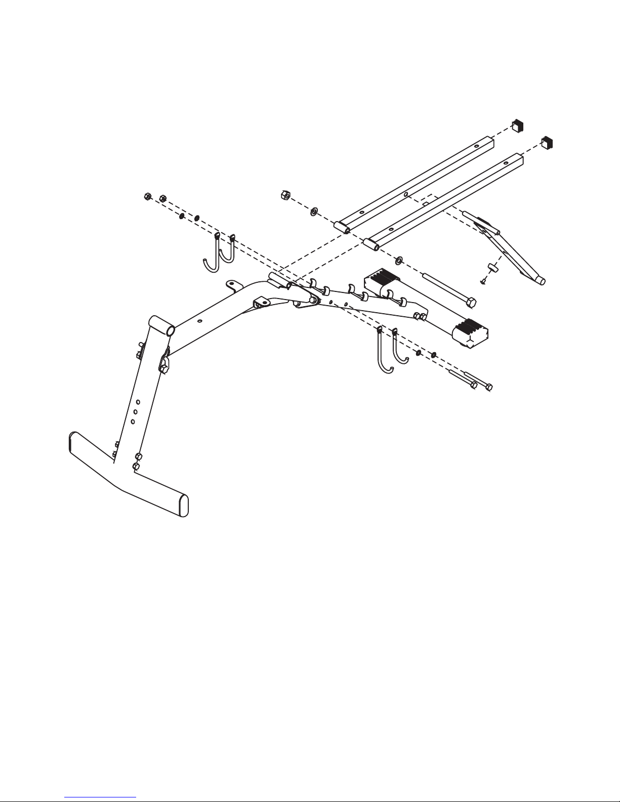
STEP 2
1
2
10
11
10
11
19
30
30
27
17
28
25
28
6
35
35
6
7
37
24
A.) Push two Square Inner Caps (#35) into the Backrest Support (#6). Push
one M6 x 15mm Screw (#24) and Rubber Bumper (#37) into the Incline Support
(#7). Attach the Incline Support (#7) in between the two Backrest Supports (#6).
B.) Attach the Pivot of the Backrest Supports (#6) to the Pivot on the Center Support
Frame (#1). Secure them with one M12 x 180mm Bolt (#17), two M12 Washers
(#28), and one M12 Nylon Locknut (#25).
C.) Attach two Long Dumbbell Pothook (#10) and Short Dumbbell Pothook (#11) to
the Back Support Frame (#2). Secure them with two M8 x 90mm Bolts (#19),
four M8 Washers (#30), and two M8 Nylon Locknuts (#27).
Page 7
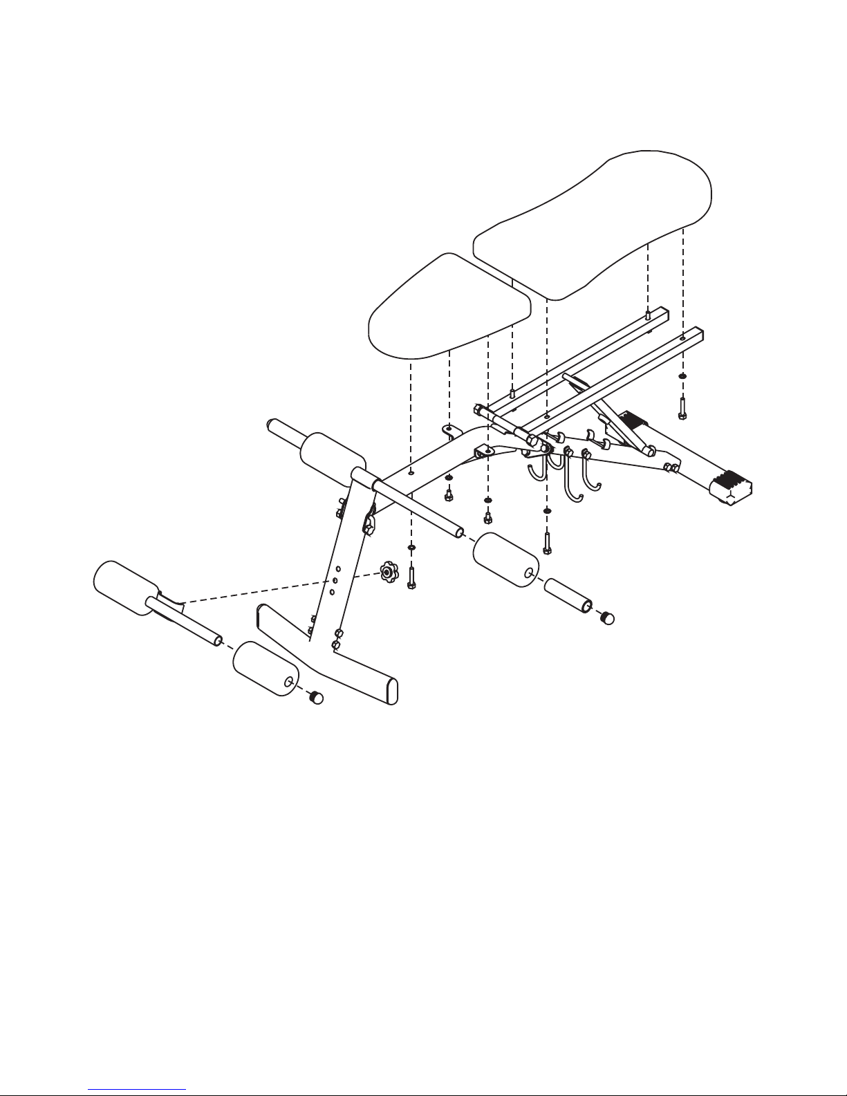
STEP 3
9
15
36
3
38
15
36
16
8
21
30
23
30
30
21
30
21
6
6
13
14
12
12
1
23
30
A.) Place the Seat (#13) onto the Center Support Frame (#1). Secure it to the two
L-shaped Brackets (#12) with two M8 x 15mm Bolts (#23) and M8 Washers
(#30). Secure the Seat to the Center Support Frame with one M8 x 45mm Bolt
(#21) and M8 Washer (#30).
B.) Place the Backrest Board (#14) onto the Backrest Supports (#6). Secure it with
four M8 x 45mm Bolts (#21) and M8 Washers (#30).
C.) Attach the Cross Tube (#9) to the Front Vertical Frame (#3). Use a Knob (#38)
to secure the Tube at selected hole. Push two Foam Rolls (#15) onto the Cross
Tube.
D.) Insert the Foam Tube (#8) halfway through the hole on the Front Vertical Frame
(#3). Push two Foam Rolls (#15) onto the Tube.
E.) Lubricate the inside of the Foam Grips (#16) with water. Slide the Foam Grips
onto the Foam Tube (#8) from both sides.
Page 8
Page 9
Page 10
STOP
Missing a Part or Need Assembly Assistance
Do Not RETURN to Store
Call our Service Line
?
.
:
1 877 227 0955---
MANUFACTURER’S WARRANTY
This warranty covers your CAP Strength product a gainst defects in materials
and workmanship when used for the intended purpose under normal use and
conditions, provided that the product receives normal maintenance and care.
This warranty lasts for: 1 year on all steel parts; 90 days on parts and; 30 days
on vinyl cushions. All of these are for the original owner only. This warranty is
not valid in cases where this product is used commercially.
CAP Strength will provide a replacement part at no charge for any part found
defective in materials or workmanship during the specified warranty period.
Under no circumstances will the manufacturer be responsible for damages or
failures that occur as a result of improper assembly or failure to operate the
product correctly. This warranty does not cover misuse, neglect, accident,
alterations or repairs made by an unauthorized service representative.
ARBITRATION
Use of this product creates an agreement between CAP Strength, Inc. and
User of Product to resolve all disputes, claims, or controversies whatsoever
arising from or relating to this product, including the validity of this arbitration
clause, by binding arbitration pursuant to Section 2 of the Federal Arbitration
Act. Maximum judgment for all causes of action shall be limited to﹩10,000.
The parties agree and understand that by using this product they choose
arbitration instead of litigation to resolve disputes. If Buyer(s) choose not to
enter into this agreement, they may return unused product for full refund.
Printed in China CAP Barbell Inc.
 Loading...