


TM
EVO™
Spray Application
Operator Manual
150300-010 Rev. A | Revised 01/2019 | ©2019 Capstan Ag Systems, Inc.

TM
Thank you for your business!
At CapstanAG, our goal is to redefine the way people do their chemical application. Our PWM
control systems have been setting the bar for maximum productivity for more than 20 years.
Our focus on performance, support, and education have dramatically changed the landscape of
agricultural chemical application.
CapstanAG specializes in creating proprietary systems for the agricultural industry, primarily
focusing on chemical and fertilizer applications. Our inventive process involves research,
engineering, design, and lab and field testing.
Service Contact Information
If a problem occurs with your system that cannot be corrected with the information in this
manual, please contact your dealer for service and technical assistance. If further assistance is
needed, contact CapstanAG.
System Purchased: _____________________________________
Dealer: ______________________________________________
Contact: _____________________________________________
Phone: _______________________________________________
Address: _____________________________________________
City,State/Province, Zip: ________________________________
Factory Service/Repairs
CapstanAG
4225 S.W. Kirklawn Ave. | Topeka, KS 66609
Hours: 8:00 a.m. to 4:00 p.m. CST
Toll-free number: (855) 628-7722 | Fax: (785) 232-7799
E-mail: prodsupport@capstanag.com | Online: www.CapstanAG.com
©2019 Capstan Ag Systems, Inc. All rights reserved. No part of this publication may be reproduced, stored in a retrieval
system, or transmited, in any form or by means electronic, mechanical, photocopying, or otherwise, without prior written
permission of Capstan Ag Systems, Inc.

TM
Contents
Chapter 1: Introduction.................................................................................... 5
This Manual.................................................................................................................................................5
System Identification...................................................................................................................................5
Chapter 2: Safety............................................................................................... 7
Signal Words............................................................................................................................................... 7
Emergency Safety........................................................................................................................................7
Pressurized Fluid Lines...............................................................................................................................7
Personal Protective Equipment................................................................................................................... 7
Battery Safety.............................................................................................................................................. 7
Chemical Safety...........................................................................................................................................8
Chapter 3: Warranty.........................................................................................9
Limited Warranty.........................................................................................................................................9
Contents
Chapter 4: Installation.................................................................................... 11
Before System Installation........................................................................................................................11
Tip Selection and Capacities.....................................................................................................................11
Nozzle Types and Component Identification............................................................................................12
7-Watt—15 Series Coil Components............................................................................................12
12-Watt—24 Series Coil Components..........................................................................................13
Assemble the Nozzle Valves.....................................................................................................................14
Move the Spray Tube Mount (Nozzle Valve Interference).......................................................... 15
Install the Nozzle Harnesses and Smart Drivers...................................................................................... 16
Install the Power to CAN X Harness....................................................................................................... 17
Install the Pressure Transmitter Module................................................................................................... 17
Install the Pressure Sensor Adapter Harness................................................................................ 18
Install the Boom Signal Transmitter Module........................................................................................... 18
Install the Shutoff Adapter............................................................................................................18
Install the CAN Bus Extension Harness...................................................................................................19
Install the CAN Terminator...................................................................................................................... 21
Install the Pressure Sensor (Optional)...................................................................................................... 21
Install the Cab Display..............................................................................................................................22
Install the Display Harness and CAN Bus Extension Harness.....................................................22
Install the Power Harness......................................................................................................................... 23
Chapter 5: Setup.............................................................................................. 25
Cab Display............................................................................................................................................... 25
Screen Descriptions...................................................................................................................................26
Advanced Menu.............................................................................................................................28
Driver Module LED Identification........................................................................................................... 32
Start the Cab Display................................................................................................................................ 33
©
2019 Capstan Ag Systems, Inc. iii EVO Spray

Shutdown the Cab Display....................................................................................................................... 33
Change the Units of Measure................................................................................................................... 34
Do the Odd/Even Test...............................................................................................................................35
Nozzle Speed Ranges................................................................................................................................36
US Measurements Nozzle Speed Ranges..................................................................................... 36
Metric Nozzle Speed Ranges........................................................................................................ 44
Chapter 6: Operation...................................................................................... 51
Start the Cab Display................................................................................................................................ 51
Shutdown the Cab Display....................................................................................................................... 51
Manual Mode Operation........................................................................................................................... 51
Shutdown the Cab Display....................................................................................................................... 53
Chapter 7: Maintenance..................................................................................55
Service the System....................................................................................................................................55
Jump Start, Weld On, or Charge the Machine..............................................................................55
Inspect the System.................................................................................................................................... 55
Clean the System.......................................................................................................................................55
Storage of the System............................................................................................................................... 55
Winterize for Storage.................................................................................................................... 55
Recommended Guidelines for Maintenance/Service................................................................................56
Baseline Evaluation Process..................................................................................................................... 56
Nozzle Valves............................................................................................................................................ 56
Clean the Nozzle Valve(s).............................................................................................................57
Plunger Seal Inspection.................................................................................................................58
Chapter 8: Schematics.....................................................................................61
System Layout...........................................................................................................................................61
Display Harness.........................................................................................................................................62
Power Harness...........................................................................................................................................63
Power Extension Harness..........................................................................................................................64
CAN Bus Extension Harness.................................................................................................................... 65
Power to CAN X Harness........................................................................................................................ 66
Nozzle Harness..........................................................................................................................................68
Chapter 9: Troubleshooting............................................................................ 71
Troubleshooting Charts............................................................................................................................. 71
Interchangeable Components.................................................................................................................... 76
Coil Test.....................................................................................................................................................76
Battery Voltage Test..................................................................................................................................77
Do a Check of the System Load Capacity............................................................................................... 78
Pressure Sensor Signal Test...................................................................................................................... 79
Power to the Pressure Sensor Input Test..................................................................................................80
Index........................................................................................................................................81

TM
Chapter 1: Introduction
This Manual
This manual includes operation, maintenance, and installation information for the system you purchased.
Make sure that all personnel have read this manual and that they thoroughly understand the safe and correct
operation and maintenance procedures. Failure to do so could result in personal injury or equipment damage.
This manual should be considered a permanent part of your system and should remain with the system at all
times and when you sell it.
Right and left sides of the system are determined by facing the direction of forward travel of the machine on
which the system is installed.
The information, screenshots, and other illustrations were correct at the time of publication. Changes can occur
without notice.
This manual contains important information on how to safely and correctly install, operate, and maintain
CapstanAG products. These instructions will help keep personnel safe, reduce downtime, and increase the
reliability and life of the equipment, its components, and related systems.
Review the safety information in the Original Equipment Manufacturer (OEM) agricultural equipment
manual(s).
Introduction
Follow the instructions (in this manual) and in the OEM agricultural equipment manual(s) for each step, to
make sure that work conditions in and around the OEM equipment are safe.
It is important for all individuals working with chemicals to understand the potential risks, necessary safety
precautions, and proper response in the event of accidental contact.
Review the OEM agricultural equipment manual(s) for chemical safety information.
Read, understand, and review the procedures in this manual and OEM agricultural equipment manual(s). Use
the Safety Data Sheets (SDS) and the required Personal Protective Equipment (PPE) for hazardous chemicals.
Please keep this manual and all enclosed documentation in an accessible location known to all operators,
installation, and maintenance personnel.
If you do not understand the CapstanAG equipment after reading this manual, please obtain the proper training
before working with equipment, to make sure that your own safety, as well as your co-workers’ safety, is
maintained.
Do not attempt to operate any equipment or system until you completely understand why, when, and how it
operates. If you are uncertain after studying this manual, please contact CapstanAG.
System Identification
Write the system name, serial number, and other information down in the Service Contact Information on
the inside cover of this manual. Your dealer will use these numbers when you order parts. File a copy of the
identification numbers in a secure place off the machine.
If you are not the original owner of this machine, it is in your interest to contact your local CapstanAG dealer
to inform them of this unit's serial number. Providing this information will help CapstanAG notify you of any
issues or product improvements.
©
2019 Capstan Ag Systems, Inc. 5 EVO Spray

TM
Introduction
©
2019 Capstan Ag Systems, Inc. 6 EVO Spray

TM
Chapter 2: Safety
Signal Words
DANGER: Indicates an imminent hazard which, if not avoided, will result in death or serious injury.
This signal word is limited to the most extreme situations, typically for machine components that, for
functional purposes, cannot be guarded.
Warning: Indicates a potential hazard which, if not avoided, could result in death or serious injury, and
includes hazards that are exposed when guards are removed. It may also be used to alert against unsafe
practices.
CAUTION: Indicates a potential hazard which, if not avoided, may result in minor or moderate injury.
It may also be used to alert against unsafe practices.
Important: This is used to draw attention to specific information that is necessary for the operation, setup, or
service of the system.
Note: This is used for additional information that can help understand or operate the system.
Safety
Emergency Safety
Fire extinguishing systems must meet the applicable OSHA requirements, and all users of portable/fixed fire
suppression equipment must know the types, limitations, and proper uses of this equipment; including hazards
involved with incipient stage firefighting.
Keep emergency numbers for doctors, ambulance service, hospital, and fire department near your telephone.
Know the location of fire extinguishers and first aid kits and how to use them.
Inspect the fire extinguisher and service the fire extinguisher regularly.
Follow the recommendations on the instructions plate.
Very small fires can be put out (extinguished) with a fire extinguisher. Use an appropriate method to extinguish
a fire (water for paper fires, and chemical extinguishers for electrical or chemical fires.
Pressurized Fluid Lines
Do not heat by welding, soldering, or using a torch near pressurized fluid lines or other flammable materials.
Pressurized lines can accidentally burst when too much heat is present.
Personal Protective Equipment
Wear close-fitting clothing and the correct personal protective equipment (PPE) for the job. See the
manufacturer’s manual or other information for correct PPE.
Battery Safety
Use the procedure in the appropriate agricultural equipment manual for connecting, disconnecting, and jumpstarting the machine’s battery.
Keep sparks and flames away from the battery. Battery gas can explode and cause serious injury. Do not smoke
in the battery charging area.
Remove jewelry, which might make electrical contact and create sparks.
©
2019 Capstan Ag Systems, Inc. 7 EVO Spray

TM
Chemical Safety
Chemicals used in agricultural applications can be harmful to your health and/or the environment if not used
correctly. Always follow all label directions for effective, safe, and legal use of agricultural chemicals.
Safety
©
2019 Capstan Ag Systems, Inc. 8 EVO Spray

TM
Chapter 3: Warranty
Limited Warranty
What does the Limited Warranty cover?
The ultimate purchaser/user (“you”), by acceptance of seller Capstan Ag Systems, Inc.’s, (“our,” “we,” or “us”)
product, assume all risk and liability of the consequences of any use or misuse by you, your employees, or
others.
All replacement components furnished under this warranty, but shipped before the failed component is returned
for evaluation, will be invoiced in the usual manner and warranty adjustments will be made after the component
claimed to be defective has been returned to and inspected and deemed defective by us at our factory.
Upon determining that a component has failed under warranty, the repaired component or replacement
component, furnished under this warranty, will be shipped at our expense, to your location. We will credit you
an amount equal to the incoming freight you paid. We shall not be responsible for installation costs. (You shall
be responsible for all customs and brokerage fees for all international transactions.)
If the component does not prove to be defective, you shall be liable for all freight, inspection and handling
costs. In no event will any claim for labor or incidental or consequential damages be allowed for removing or
replacing a defective product. Warranty will be denied on any component which has been subject to misuse,
abuse, accidents, or alterations, or to improper or negligent use, maintenance, storage or transportation and
handling.
Warranty
Our liability under this warranty, or for any loss or damage to the components whether the claim is based
on contract or negligence, shall not, in any case, exceed the purchase price of the components and upon the
expiration of the warranty period all such liability shall terminate. The foregoing shall constitute your exclusive
remedy and our exclusive liability.
The terms of this warranty do not in any way extend to any product which was not manufactured by us or one of
our affiliates.
While necessary maintenance or repairs on your Capstan Ag Systems, Inc. product can be performed by
any company, we recommend that you use only authorized Capstan Ag Systems, Inc. dealers. Improper or
incorrectly performed maintenance or repair voids this warranty.
The foregoing warranty is exclusive and is in lieu of all other warranties expressed or implied. We shall not be
liable for any incidental or consequential damages resulting from any breach of warranty.
Your exclusive remedy for breach of warranty shall be repair or replacement of defective component(s):
Provided, if the component(s) are incapable of being repaired or replaced, your exclusive remedy shall be credit
issued, but such credit shall not exceed the purchase price of the components.
On any claim of any kind, including negligence, our liability for any loss or damage arising out of, or from the
design, manufacture, sale, delivery, resale, installation, technical direction of installation, inspection, repair,
operation of use of any products shall in no case exceed the purchase price allocable to the components.
In no event, whether as a result of breach of contract or warranty or alleged negligence, shall we be liable for
incidental or consequential damages, including, but not limited to: personal injury, loss of profits or revenue,
loss of use of equipment or any associated equipment, cost of capital, cost of substitute equipment, facilities or
services, downtime costs, environmental damage, crop losses, or claims of customers of you for such damages.
What is the period of coverage?
We warrant to you, that our products are free from defects in material and workmanship in normal use and
service for a period of one year from date of purchase.
©
2019 Capstan Ag Systems, Inc. 9 EVO Spray

TM
How do you get service?
Our obligation under this warranty shall be limited to the repairing or replacing at our option, the component
which our inspection discloses to be defective, free of charge, return freight paid by us, provided you: (i) Notify
us of defect within thirty (30) days of failure; (ii) Return the defective component to us, freight prepaid; (iii)
Complete the Owner Registration Form and returned it to us; and (iv) Establish that the product has been
properly installed, maintained and operated in accordance with our instructions or instructions contained in our
operations or maintenance manuals and within the limits of normal usage.
Any claim for breach of our warranty must be in writing addressed to us and must set forth the alleged defect
in sufficient detail to permit its easy identification by us. All breach of warranty claims must be made within
thirty (30) days after expiration of the warranty period which is applicable to the defective product. Any breach
of warranty claim not timely made will not be honored by us and will be of no force and effect. Any component
that needs to be repaired or evaluated for warranty has to be authorized before return. Contact the factory
(785-232-4477) to get a Return Materials Authorization (RMA #). This helps to track the part coming into the
factory for repair or replacement.
Before returning any component to the factory, clean the component as well as possible to remove any dirt or
chemical residue. Components received at the factory that are not clean, will be returned and warranty denied.
After receiving your RMA #, package the part, making sure to include the RMA #, your name, customer’s
name, your address and phone number and description of problems or failure. Then ship to:
Warranty
Capstan Ag Systems, Inc.
Attn: Warranty/Repair
4225 SW Kirklawn Ave.
Topeka, KS 66609
Phone: (785) 232-4477
Fax: (785) 232-7799
Hours: 8 a.m. - 4:30 pm CST
How does state law relate to this Limited Warranty?
Some states do not allow limitations on how long an implied warranty lasts, so the above limitation may not
apply to you.
Some states do not allow the exclusion or limitation of incidental or consequential damages, so the above
limitation or exclusion may not apply to you.
This warranty gives you specific legal rights, and you may also have other rights which vary from state to state.
1
1
Rev. Date 7/15/2014
©
2019 Capstan Ag Systems, Inc. 10 EVO Spray

TM
Chapter 4: Installation
Before System Installation
Before assembly and installation, read the installation information carefully. Make sure that you have all of the
parts in the kits. Read all of the instructions in this document, the system operator manual, and the machine
manuals. The system operator manual includes information on operation, adjustments, troubleshooting, and
maintenance.
For further assistance contact your CapstanAG representative.
Tip Selection and Capacities
Installation
Fig. 1:
When selecting the correct tips:
• Always use 110° spray angle tips and maintain the boom height of at least 24 in (61 cm). If 80° spray
angle tips are used, maintain the boom height of at least 36 in (91 cm).
• The tip selection chart, in the operation section of this manual, describes the speed ranges that can be
expected when operating with a rate controller at various rates and pressures.
•
To use the chart, select the application rate (1).
•
Move down the column to the desired speed range (2).
•
Select a tip (3) that provides the boom pressure you wish to spray (4).
©
2019 Capstan Ag Systems, Inc. 11 EVO Spray

TM
Nozzle Types and Component Identification
Important: Make sure that you have the correct nozzles and components for your system.
7-Watt—15 Series Coil Components
Installation
Fig. 2:
Item Description Arag High
Flow Part
Number
1 7-Watt Coil Assembly 116189-111 116189-111 116189-111 116189-111
2 Plunger Assembly 716009-114 716009-114 716009-114 716009-114
3 Inner-valve O-ring 715022-204 715022-204 715022-204 715022-204
4 Flybody 116182-201 116182-001 116186-001 116188-001
5 FlyBody Stem (Tip) O-ring 715022-211 715022-210 715022-210 715022-210
6 Nozzle Body FlyBody O-
ring
©
2019 Capstan Ag Systems, Inc. 12 EVO Spray
715022-212 715022-205 715022-202 715022-206
Arag Part
Number
Tee Jet Part
Number
Wilger Part
Number

TM
12-Watt—24 Series Coil Components
Installation
Fig. 3:
Item Description Arag High
Flow Part
Arag Part
Number
Tee Jet Part
Number
Wilger Part
Number
Number
1 12-Watt Coil Assembly 116189-111 625147-011 625147-011 625147-011
2 Plunger Assembly 716009-114 716009-114 716009-114 716009-114
3 Inner-valve O-Ring 715022-204 715022-204 715022-204 715022-204
4 Flybody 116182-201 116182-002 116186-002 116188-002
5 FlyBody Stem (Tip) O-ring 715022-211 715022-210 715022-210 715022-210
6 Nozzle Body FlyBody O-
715022-212 715022-205 715022-202 715022-206
ring
©
2019 Capstan Ag Systems, Inc. 13 EVO Spray

TM
Assemble the Nozzle Valves
1.
Remove the drip check valve and diaphragm cap from each nozzle body.
Installation
Fig. 4:
2.
Install the O-rings (1) onto the flybody nozzle assembly (2).
3.
Install the nozzle valve assembly onto the nozzle body (3).
4.
Tighten the flybody (4) until the coil housing does not spin.
The nozzle valves only need to be snug to prevent leakage.
5.
Install and tighten the spray tip to a port (5) on the nozzle body.
6.
Repeat steps 1 to 5 for all nozzle valve assemblies.
©
2019 Capstan Ag Systems, Inc. 14 EVO Spray

TM
Move the Spray Tube Mount (Nozzle Valve Interference)
Installation
Fig. 5:
If a spray tube mount (1) prevents nozzle valve installation:
1.
Loosen the spray tube mount bolts (2).
2.
Slide the spray tube mount away from the nozzle valve assembly (3) until the nozzle valve assembly can be
properly installed.
3.
Tighten the spray tube mount bolts.
©
2019 Capstan Ag Systems, Inc. 15 EVO Spray

TM
Install the Nozzle Harnesses and Smart Drivers
Installation
Fig. 6:
Each nozzle harness will have a smart driver already installed.
1.
Put the smart drivers in serial number order with the lowest number to the left side of the machine.
The smart driver serial number (1) is shown on the front of the smart driver.
2.
Route the nozzle harnesses along the boom with the smart driver toward the center of the machine.
Make sure that there is enough slack in the harnesses to raise and lower the booms and to avoid pinch points
at the boom fold and pivot points.
3.
Use cable ties to attach the smart driver and the nozzle harnesses to the machine.
©
2019 Capstan Ag Systems, Inc. 16 EVO Spray

TM
Install the Power to CAN X Harness
Installation
Fig. 7:
1.
Install the power to CAN X harness at the center of the machine.
2.
Use cable ties to attach the harness to the machine.
Install the Pressure Transmitter Module
Fig. 8:
1.
Install the pressure transmitter module (1) to the pressure connector (2) on the power to CAN X harness.
2.
Use cable ties to attach the module to the machine.
©
2019 Capstan Ag Systems, Inc. 17 EVO Spray

TM
Install the Pressure Sensor Adapter Harness
1.
Connect one end of the pressure sensor adapter harness to the pressure transmitter module.
2.
Route the harness to the pressure sensor.
3.
Connect the other end of the harness to the pressure sensor.
Install the Boom Signal Transmitter Module
Installation
Fig. 9:
1.
Install the boom signal transmitter module (1) to the shutoff connector (2) on the power to CAN X harness.
2.
Use cable ties to attach the module to the machine.
Install the Shutoff Adapter
1.
Install one end of the shutoff adapter into the boom signal transmitter module.
2.
Route and connect the other ends of the shutoff adapter as necessary.
©
2019 Capstan Ag Systems, Inc. 18 EVO Spray

TM
Install the CAN Bus Extension Harness
Installation
Fig. 10:
1.
Connect the CAN Bus extension harness (1), of the correct length, to the left boom/left truck connector (2)
on the power to CAN X harness.
2.
Connect the other end of the CAN Bus harness to the smart driver module (3) closest to the center left side
of the machine.
3.
Connect another CAN Bus harness (4), of the correct length, to the other port (5) on the smart driver at the
center left side of the machine.
4.
Route the CAN Bus harness to the next smart driver (6) to the left.
5.
Connect the other end of the harness to the next smart driver.
6.
Continue installing CAN Bus harnesses, of the correct length, until you get to the last smart driver on the left
of the machine.
©
2019 Capstan Ag Systems, Inc. 19 EVO Spray

TM
Fig. 11:
7.
Connect the CAN Bus extension harness (1), of the correct length, to the right boom/right truck connector
(2) on the power to CAN X harness.
8.
Connect the other end of the CAN Bus harness to the smart driver module (3) closest to the center right side
of the machine.
9.
Connect another CAN Bus harness (4), of the correct length, to the other port (5) on the smart driver at the
center right side of the machine.
10.
Route the CAN Bus harness to the next smart driver (6) to the right.
11.
Connect the other end of the harness to the next smart driver.
12.
Continue installing CAN Bus harnesses, of the correct length, until you get to the last smart driver on the
right of the machine.
Installation
©
2019 Capstan Ag Systems, Inc. 20 EVO Spray

TM
Install the CAN Terminator
Installation
Fig. 12:
1.
On the left most smart driver, install a CAN terminator (1) into the open CAN port (2).
2.
On the right most smart driver, install a CAN terminator into the open CAN port.
Install the Pressure Sensor (Optional)
The use of a CapstanAG pressure sensor is optional. The EVO Spray system is designed to integrate with the
existing boom pressure sensor on the machine.
1.
If you want to use the Capstan AG pressure sensor, remove the existing machine pressure sensor from the
boom manifold.
2.
Install the tee fitting and other hardware with sealant tape.
3.
Vertically install the new pressure sensor with sealant tape.
Note: If you must install the pressure sensor horizontally make sure that there is an angle to it to keep liquid
from settling inside the pressure sensor.
Important: Do not over-tighten the pressure sensor when installing into plastic tee fittings.
4.
Install the existing machine pressure sensor with sealant tape.
©
2019 Capstan Ag Systems, Inc. 21 EVO Spray

TM
Install the Cab Display
Installation
Fig. 13:
Mount the cab display (1) in the cab of the machine with the hardware (2) supplied with the kit.
Make sure that the cab display is within view and reach of the operator.
Install the Display Harness and CAN Bus Extension Harness
Fig. 14:
1.
Install one end of the display harness (1) into the connector at the back of the cab display (2).
2.
Route the display harness to the back of the cab of the machine.
3.
Connect the GPS connector (3) to the GPS source.
©
2019 Capstan Ag Systems, Inc. 22 EVO Spray

TM
4.
At the back of the cab, connect the display harness to the CAN Bus extension harness (4).
5.
Route the CAN Bus extension harness to the power to CAN X harness at the back of the machine.
6.
Connect the other end of the CAN Bus extension harness to the display connector (5) on the power to CAN
X harness.
Install the Power Harness
1.
Connect one end of the power harness to the power to CAN X harness.
2.
Route the power harness to the battery.
3.
Connect the battery harness positive (+) red cable to the positive terminal of the battery.
4.
Connect the battery harness negative (-) black cable to the battery ground terminal.
Installation
©
2019 Capstan Ag Systems, Inc. 23 EVO Spray

TM
Installation
©
2019 Capstan Ag Systems, Inc. 24 EVO Spray

TM
Chapter 5: Setup
Cab Display
Setup
Fig. 15:
The cab display has seven buttons to navigate and control the system. A screen on the cab display shows
immediate information and gives access to the menu items.
(1)
(2)
(3)
(4)
(5)
(6)
POWER Button—Press to turn on or off the display
MENU Button—Press to see the Main Menu screen
INCREASE and DECREASE Buttons—Press to move through the menu items
ENTER Button—Press to accept changes or go to the next screen
ESCAPE Button—Press to cancel or go back to the previous screen.
MANUAL/BYPASS Button—Press to use the manual operation or bypass mode.
©
2019 Capstan Ag Systems, Inc. 25 EVO Spray

TM
Screen Descriptions
Setup
Fig. 16:
Main Menu
The Main Menu screen (1) includes this information:
1.
Backlight
2.
Alarm Volume
3.
Turn Compensation
4.
Rate Sync
5.
Pressure Increment
6.
Advanced Menu
Backlight
The Change Backlight screen (2) gives choices of the brightness of the LCD screen and light behind the keypad
for low light conditions.
Range: 1 to 5 (Dimmest to Brightest)
When selections 1 or 2 are active (low ambient light conditions) the keypad buttons become back-lit.
Alarm Volume
The Change Alarm Volume screen (3) let you change the volume level of the alarm.
To silence the alarm, select Off.
Range: Off to 5 (Quiet to Loudest)
©
2019 Capstan Ag Systems, Inc. 26 EVO Spray

TM
Turn Compensation
The Turn Compensation screen (4) lets you turn the feature on or off.
Range: Enabled or Disabled
Rate Sync
The Rate Sync screen (5) lets you turn the feature on or off.
Range: On or Off
When the feature is on the range is 5 Hz to 10 Hz.
Rate Sync™ uses real time speed change to determine the proper duty cycle for the appropriate boom section. It
is used to make the system react faster to speed changes.
Setup
Note: A 5 Hz GPS connection is required for Rate Sync™ to operate properly. If a 5 Hz GPS signal is not
available, the Rate Sync
™
feature should be set to Off.
Rate Sync™ turned off disables speed change corrections. GPS connection is not needed with the Rate Sync
feature set to Off.
Pressure Increment
The Pressure Increment screen (7) lets you change pressure increment per toggle of the INCREASE or
DECREASE button.
Range: 1 to 10
™
©
2019 Capstan Ag Systems, Inc. 27 EVO Spray

TM
Advanced Menu
The Advanced Menu screens include this information:
Setup
Fig. 17:
System Gain
The System Gain screen (1) lets you make changes to the system pressure control.
Range: 1 to 20
System Gain is the first pressure control parameter in the display menu system. System Gain changes the total
response of system according to the same ratio between the individual P Gain and I Gain values. It is the first
menu item to utilize when tuning the pressure control.
Increasing the System Gain makes the system react faster to pressure changes.
Decreasing the System Gain makes system react slower to pressure changes.
P Gain
The P Gain screen (2) lets you change the value.
Range: 2.00 to 8.5
P (Proportional) gain is the second pressure tuning parameter in the display menu. Proportional gain determines
the initial speed at which display drives the duty cycle toward the target value. Stabilize an oscillating system by
selecting a lower number. Speed up a sluggish system by selecting a higher number.
©
2019 Capstan Ag Systems, Inc. 28 EVO Spray

TM
I Gain
The I Gain screen (3) lets you change the value.
Range: 0.05 to 0.35
I (Integral) Gain, the third pressure tuning parameter in the display, determines the acceleration driving duty
cycle to the target value. To stabilize an oscillating system, use a lower number. To speed up a sluggish system,
use a higher number.
Run/Hold Delay
The Run/Hold Delay screen (4) lets you change the delay when the display starts at a preset value (50% or the
last known duty cycle) allowing the rate controller to stabilize before making larger pressure control changes.
Range: 0 to 6
When the boom is turned on and the run/hold signal is returned, the display will begin to control pressure by
first resuming the pulsing at the previous duty cycle before the boom was shutoff.
The Hold will show in the Diagnostics area on the main operating screen, to alert the operator that the
initialization delay has been activated.
The start-up delay time is equal to the run/hold delay time. This allows the flow control system to resume
control and attain rate stability. Once the delay period has elapsed, the display will resume pressure control.
Setup
The diagnostic readout area will read Hold and count down the seconds to alert the operator that the Run/Hold
Delay has been activated. When the hold count down is finished, the display will read Run in diagnostics area.
At this point, the display is controlling pressure once again.
Low Pressure Shutoff
The Low Pressure Shutoff screen (5) lets you change when the system turns off the nozzle valves when the
pressure decreases.
Range: Off or 8 psi
This feature is intended to duplicate the effect of the nozzle drip checks found on sprayers. To alert the operator
that the low pressure shutoff feature has been activated, low PSI shutoff will appear in the diagnostic readout
area.
When the pressure rises above 12 PSI again, the display will pulse at 50% duty cycle for the start-up delay
period and then will resume pressure control.
When set to Off, the display will maintain a minimum duty cycle percentage, equal to the pulse frequency,
regardless of either low or zero pressure.
Pwm Frequency
The Pwm Frequency screen (6) lets you change the value.
Range: 3 to 30 Hz
CapstanAG does not recommend pulse frequencies slower than 10 Hz in sprayer applications.
©
2019 Capstan Ag Systems, Inc. 29 EVO Spray

TM
Setup
Fig. 18:
Units
The Units screen (1) lets you change the units of measure.
Range: US, SI
Nozzle Spacing
The Nozzle Spacing screen (2) lets you change the system nozzle spacing.
Range: 10 to 40
Module Location
The Module Location screen (3) lets you see smart driver module location and information and change the
order if necessary.
To change the order follow the prompts on the display.
Note: The smart driver module location must be correct for the sections to operate in the correct order.
Section Size
The Section Size screen (4) lets you change the number of nozzles per section.
The correct number of nozzles for each section must be entered manually for the system to operate correctly.
This feature lets the nozzles on a specific section turn on, and for accurate turn compensation.
Note: The section size programming must be done after doing the module location setup.
Low Flow Menu
The Low Flow Menu (5) is for use with the John Deere R Series Sprayers only. See a CapstanAG representative
for more information.
©
2019 Capstan Ag Systems, Inc. 30 EVO Spray

TM
Setup
Fig. 19:
Pressure Sensor Menu
Select the Pressure Sensor Menu (1) to see the Pressure Sensor screen (2).
Sensor Offset
The Sensor Offset screen (3) lets you manipulate this setting if a difference in the pressure is noticed across
separate pressure sensors, such as between the display pressure reading and the rate controller pressure display
from a secondary pressure sensor.
Range: -10 to 10
Note: The system requires a greater quality pressure sensor relative to pressure sensors which only report a
screen value. In most cases, the adjustment will be correcting the value to the least accurate sensor.
Sensor volt min
The Sensor volt min screen (4) lets you change the minimum voltage of the pressure sensor.
Range: 0.5 to 1.0
If you are using a CapstanAG™ pressure sensor leave the default value of 0.5. Change the value as needed if
you are using another type of pressure sensor.
Sensor volt max
The Sensor volt max screen (5) lets you change the maximum voltage of the pressure sensor.
Range: 4.5 to 5.0
Sensor pressure max
The Sensor pressure max screen (6) lets you change the maximum pressure of the pressure sensor.
Range: 50 to 250
©
2019 Capstan Ag Systems, Inc. 31 EVO Spray

TM
Diagnostics
Fig. 20:
The Diagnostics screen (1) shows system information that is useful for troubleshooting and/or diagnostics.
Odd/Even test is the one menu line a person can enter and utilize in this Diagnostic page. Do the Odd/Even Test
for setup and troubleshooting.
Setup
Driver Module LED Identification
Fig. 21:
The system will have several smart driver modules (1). Each module has 3 LEDs:
(2)
(3)
Green—Power
Solid Illumination—12 V
Blue—CAN
Blinking Illumination—5 Hz
(4)
©
2019 Capstan Ag Systems, Inc. 32 EVO Spray
Red—Duty Cycle/Frequency Feedback
Blinking Illumination—5 Hz

TM
The system will have one pressure transmitter module (5) and one boom signal transmitter module (6). Each
module has 3 LEDs:
Setup
(7)
(8)
(9)
Green—Power
Solid Illumination—12 V
Blue—CAN
Blinking Illumination—5 Hz
Red—Feedback Information
Blinking Illumination—5 Hz
Start the Cab Display
Fig. 22:
1.
Start the machine.
2.
Press the POWER button (1) on the cab display.
3.
Set the desired pressure on the cab display.
4.
Start the rate controller, if necessary.
5.
Make sure that the rate settings are correct on the rate controller.
6.
Turn on the boom sections to spray.
Shutdown the Cab Display
1.
Turn off the boom sections.
2.
Press the POWER button on the cab display.
3.
Turn off the machine.
©
2019 Capstan Ag Systems, Inc. 33 EVO Spray

TM
Change the Units of Measure
Setup
Fig. 23:
1.
Press the MENU button (1).
2.
Use the UP or DOWN arrow buttons (2) to select Advanced Menu (3) from the Main Menu.
3.
Press the ENTER button (4).
4.
Use the UP or DOWN arrow buttons to select Units (5) from the Advanced Menu.
5.
Press the ENTER button.
6.
Use the UP or DOWN arrow buttons to select the desired units of measure (6) on the Units screen.
7.
When the desired unit of measure is highlighted, press the ENTER button.
©
2019 Capstan Ag Systems, Inc. 34 EVO Spray

TM
Do the Odd/Even Test
Testing with Odd/Even test will actuate only the odd valves then only the even valves.
Setup
Fig. 24:
1.
Press the MENU button (1).
2.
Use the UP or DOWN arrow buttons (2) to select Advanced Menu (3) from the Main Menu.
3.
Press the ENTER button (4).
4.
Use the UP or DOWN arrow buttons to select Diagnostics (5) from the Advanced Menu.
5.
Press the ENTER button.
6.
Use the UP or DOWN arrow buttons to select Odd/Even Test (6) from the Diagnostics screen.
7.
Press the ENTER button.
8.
Use the UP or DOWN arrow buttons to select Odd (7) from the Selection list on the Odd/Even Test screen.
9.
Press the ENTER button.
10.
Make sure that all of the odd nozzles are operating.
Note: If two adjacent nozzles are pulsing, one nozzle must be moved to skip a connector on the harness.
11.
Use the UP or DOWN arrow buttons to select Even (8) from the Selection list on the Odd/Even Test
screen.
12.
Press the ENTER button.
13.
Make sure that all of the even nozzles are operating.
Note: If two adjacent nozzles are pulsing, one nozzle must be moved to skip a connector on the harness.
14.
Use the UP or DOWN arrow buttons to select Disabled (9) from the Selection list on the Odd/Even Test
screen.
15.
Press the ESCAPE button (10) to exit the Odd/Even Test screen.
©
2019 Capstan Ag Systems, Inc. 35 EVO Spray

TM
Nozzle Speed Ranges
US Measurements Nozzle Speed Ranges
Nozzle Spacing—15 in
Setup
©
2019 Capstan Ag Systems, Inc. 36 EVO Spray

TM
Setup
©
2019 Capstan Ag Systems, Inc. 37 EVO Spray

TM
Setup
©
2019 Capstan Ag Systems, Inc. 38 EVO Spray

TM
Nozzle Spacing—20 in
Setup
©
2019 Capstan Ag Systems, Inc. 39 EVO Spray

TM
Setup
©
2019 Capstan Ag Systems, Inc. 40 EVO Spray

TM
Setup
©
2019 Capstan Ag Systems, Inc. 41 EVO Spray

TM
Blended Pulse™ Droplet Classification Table-US Measurements
Setup
©
2019 Capstan Ag Systems, Inc. 42 EVO Spray

TM
Setup
©
2019 Capstan Ag Systems, Inc. 43 EVO Spray

TM
Metric Nozzle Speed Ranges
Nozzle Spacing—38 cm
Setup
©
2019 Capstan Ag Systems, Inc. 44 EVO Spray

TM
Setup
©
2019 Capstan Ag Systems, Inc. 45 EVO Spray

TM
Nozzle Spacing—50 cm
Setup
©
2019 Capstan Ag Systems, Inc. 46 EVO Spray

TM
Setup
©
2019 Capstan Ag Systems, Inc. 47 EVO Spray

TM
Blended Pulse™ Droplet Classification Table-Metric
Setup
©
2019 Capstan Ag Systems, Inc. 48 EVO Spray

TM
Setup
©
2019 Capstan Ag Systems, Inc. 49 EVO Spray

TM
Setup
©
2019 Capstan Ag Systems, Inc. 50 EVO Spray

TM
Chapter 6: Operation
Start the Cab Display
Operation
Fig. 25:
1.
Start the machine.
2.
Press the POWER button (1) on the cab display.
3.
Set the desired pressure on the cab display.
4.
Start the rate controller, if necessary.
5.
Make sure that the rate settings are correct on the rate controller.
6.
Turn on the boom sections to spray.
Shutdown the Cab Display
1.
Turn off the boom sections.
2.
Press the POWER button on the cab display.
3.
Turn off the machine.
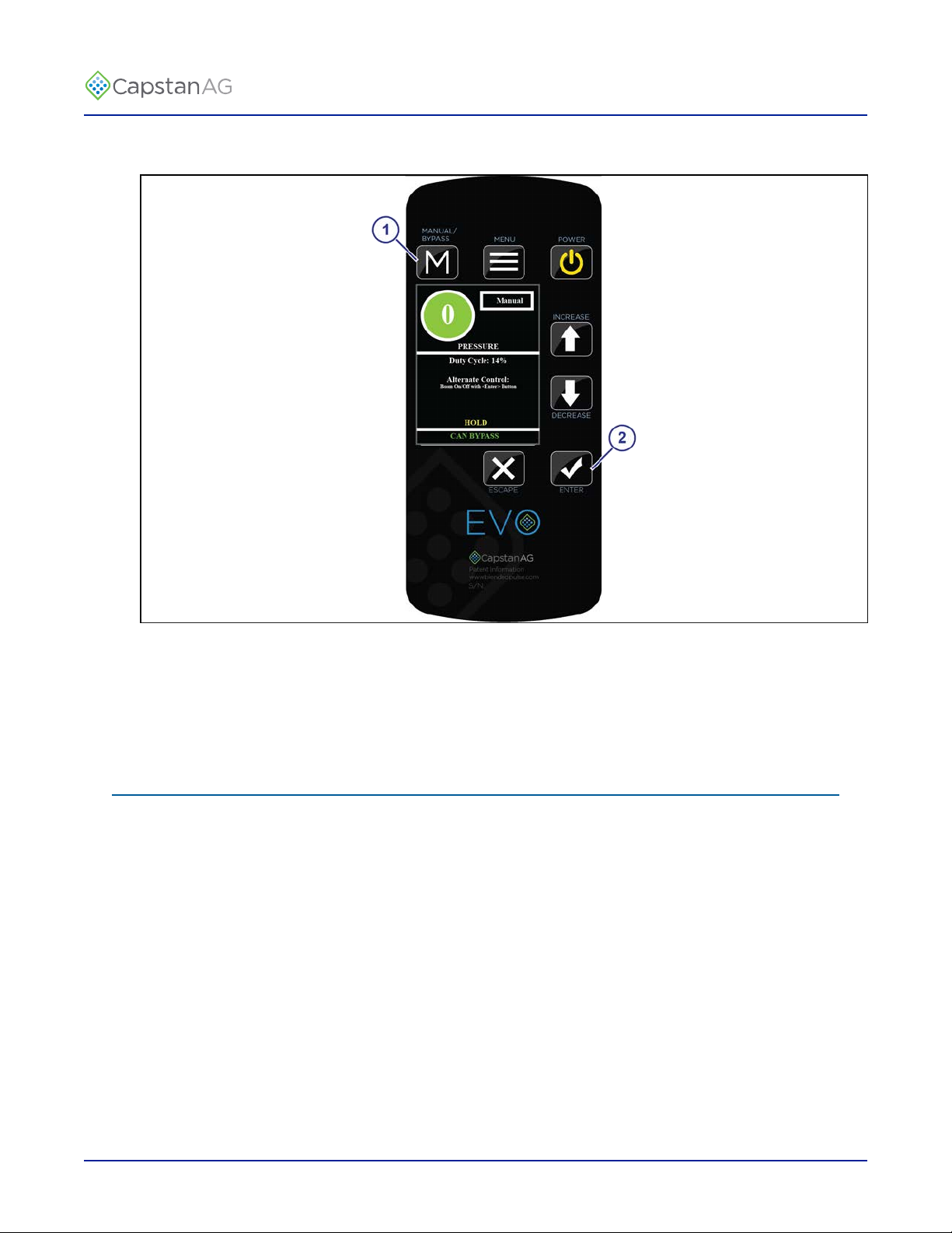
Manual Mode Operation
Manual mode is usually used for troubleshooting purposes, should the operator encounter rate or pressure
instability issues while spraying. Switching to manual mode could allow the operator to finish a field or job
before contacting the dealer to solve the problem.
Manual mode will keep the nozzle valves at a constant duty cycle, which is useful when optimizing rate
controller tuning.
©
2019 Capstan Ag Systems, Inc. 51 EVO Spray

TM
Operation
Fig. 26:
Press the MANUAL/BYPASS button (1) to enter manual mode operation.
Use the UP or DOWN arrows (2) to control the nozzle duty cycle, regardless of the pressure sensor reading or
target pressure set point.
©
2019 Capstan Ag Systems, Inc. 52 EVO Spray
TM
ByPass Mode
Operation
Fig. 27:
To enter into bypass mode, press and hold the MANUAL/BYPASS (1).
Press the ENTER button (2) to turn the booms on and off.
ByPass Mode provides a way to continue operation without CAN Communication.
Shutdown the Cab Display
1.
Turn off the boom sections.
2.
Press the POWER button on the cab display.
3.
Turn off the machine.
©
2019 Capstan Ag Systems, Inc. 53 EVO Spray

TM
Operation
©
2019 Capstan Ag Systems, Inc. 54 EVO Spray

TM
Chapter 7: Maintenance
Service the System
CAUTION: Before operation or service to the system, read and understand the machine’s operator
manual and the system operator manual. Chemical residue may be present on/in the OEM equipment.
Use the correct personal protective equipment.
Before servicing the system or plumbing components, release the pressure and empty any product from the
system and liquid delivery lines.
Jump Start, Weld On, or Charge the Machine
If jump starting the machine, make sure that you trip the circuit breaker to prevent damage to the system.
If charging the machine’s batteries or welding on the machine, trip the circuit breaker.
Inspect the System
• Inspect the hoses for cuts, nicks, or abrasions before each use. Replace any damaged hoses immediately.
• Make sure that the strainers are clean.
• Make sure that all hoses and wiring are secure.
• Do a check for loose hoses, mounting hardware, and other components. Tighten if necessary.
• Do a check for damaged or missing decals. Replace if necessary.
Maintenance
Clean the System
• Thoroughly clean the system after each use.
• Avoid high-pressure spray when cleaning the spray system components, valves, and wiring connectors.
Storage of the System
Thoroughly clean the implement and the system before any long storage.
Winterize for Storage
Do not use fertilizer to winterize! The use of fertilizer to winterize will cause internal damage to the nozzle
valves.
Thoroughly clean the spray system before winter storage.
Flush the spray system with clean water.
Winterize the spray system with RV antifreeze for winter storage. Proper winterizing of the machine with a
CapstanAG system installed on it is essential. Make sure that the booms are completely full of antifreeze at
100% strength and that the solenoids are pulsed (sprayed) for a few minutes to make sure that the antifreeze
remaining in the solenoids is at full strength.
©
2019 Capstan Ag Systems, Inc. 55 EVO Spray

TM
Recommended Guidelines for Maintenance/Service
When servicing a system, CapstanAG recommends doing these:
• Do the baseline service checks and verify the original setup values in this manual.
• Identify individual performance problems. Evaluate possible causes and corrections for performance
issues.
• Troubleshoot individual components and replace if needed.
Important: The primary service tool will be a multimeter that can measure voltage and resistance (ohms).
Baseline Evaluation Process
1.
Make sure that the voltage readings are correct.
2.
Do a visual check of all wire connections, harnesses, and connectors. Make sure that there are no loose,
broken, or damaged parts.
3.
Make sure that the correct tip size is used for the application.
4.
Make sure that the liquid product plumbing and the strainer(s) are clean.
5.
Do a like component swap test to see if the failure follows the component.
6.
Repair or replace any damaged components.
7.
Do the system tests.
Maintenance
See the system testing information in this manual.
Nozzle Valves
Plugged nozzle valves can be classified into two categories:
• Plunger blockage
• Plunger stuck
Plunger blockage results when larger debris catches between the orifice and plunger seal. This is the smallest
flow passage within the nozzle valve.
Stuck plungers result when smaller debris collects around the barrel of the plunger and binds the plunger in
place. Symptoms of a blocked or stuck plunger are:
• Constant application
• Leaking when the nozzle is shut off
• No application
Note: Pinched or split O-rings will also cause nozzles to drip when shutoff.
Note: Operating a plugged nozzle valve for extended periods of time may result in a nozzle valve coil failure.
Immediately clean any plugged nozzle valves.
©
2019 Capstan Ag Systems, Inc. 56 EVO Spray

TM
Clean the Nozzle Valve(s)
Warning: Chemical residues may be present in the agricultural equipment. Always use the proper
personal equipment to avoid personal injury.
1.
Release pressure from the system before servicing.
2.
Clean the system before installation or service of the fittings, hoses, valves, or nozzles.
Fig. 28:
3.
Use pliers around the flybody (1) to hold the assembly with the coil harness facing the ground.
4.
Rotate the coil (2) counter-clockwise to remove the coil from the valve body.
5.
Remove the plunger (3) from the coil.
6.
Inspect the O-ring (4) on the coil.
7.
Inspect the O-rings (5) on the flybody.
8.
Wash the nozzle valve components to remove any debris.
9.
Inspect the plunger for wear or damage.
10.
If there is wear or damage to the plunger, replace the plunger.
11.
Inspect the flybody.
Make sure that the orifice is not plugged with debris, worn, or damaged.
12.
If there is wear or damage to the orifice, replace the flybody.
13.
Wash the nozzle body components to remove any debris.
Maintenance
Important: Do not use brake cleaner. Brake cleaner can damage the seal.
Important: During installation, apply 40 lbf in of torque to the coil when it threads into the valve body to
properly seat the O-ring.
©
2019 Capstan Ag Systems, Inc. 57 EVO Spray

TM
Plunger Seal Inspection
Maintenance
Fig. 29:
After extended use, the plunger seal will wear a groove (1) where the seal impacts the hard orifice seat. Replace
plunger if worn or damaged.
As the groove deepens the pressure capacity of the valve will decrease until the pressure capacity interferes with
the operating pressure of the system.
The result is erratic pulsing, often described as “flickering.” The system will operate normally at lower
pressures until replacement parts can be installed. High operating pressures and abrasive chemicals will
accelerate the wear of the plunger seal material.
©
2019 Capstan Ag Systems, Inc. 58 EVO Spray

TM
Fig. 30:
Maintenance
When replacement of the plunger is necessary, make sure that you have the correct plunger:
(1)
(2)
(3)
Standard Flow—4 slots on the outside
Standard Flow—2 slots on the outside
Heavy Flow—The spring (4) on the plunger has a larger diameter than the spring on the standard
valve plunger.
Make sure that the plunger seats are still smooth and not pitted.
(1)
(2)
A plunger seat on a new valve body
Examples of a worn plunger seat on a valve body
©
2019 Capstan Ag Systems, Inc. 59 EVO Spray

TM
Maintenance
©
2019 Capstan Ag Systems, Inc. 60 EVO Spray

TM
Chapter 8: Schematics
System Layout
Schematics
Fig. 31:
Callout Description Callout Description
(1)
(2)
(3)
(4)
(5)
(6)
(7)
©
2019 Capstan Ag Systems, Inc. 61 EVO Spray
Power to CAN X Harness
CAN Bus Extension Harness
Display Harness
Cab Display
Power Harness
Pressure Transmitter Module
Pressure Sensor Adapter Harness
(8)
(9)
(10)
(11)
(12)
(13)
(14)
Boom Signal Transmitter Module
CAN Bus Extension Harness (Plug to
Plug)
Smart Driver Module
CAN Terminator
Nozzle Harness
Nozzle Valve Assembly
Boom Shutoff Adapter

TM
Display Harness
Fig. 32:
Table: Display Connector (1) Pinout—12-pin DT Plug
Pin Description Color Pin Description Color
1 Power with Fuse Red 7 GPS Rx Black/White
2 Ground Black 8 Plug
Schematics
3 Synch Blue 9 GPS Ground Blue/White
4 CAN Hi Yellow 10 Plug
5 CAN Lo Green 11 Plug
6 AI Ground Brown 12 Plug
5 A Fuse (2).
Table: GPS Connector (3) Pinout—DB9 Male Connector
Pin Description Color Pin Description Color
1 6
2 GPS Rx Black/White 7
3 8
4 9
5 GPS Ground Blue/White
Table: CAN Extension Harness Connector (4) Pinout—6-pin DT Receptacle
Pin Description Color Pin Description Color
1 Power Red 4 CAN Hi Yellow
2 Ground Black 5 CAN Lo Green
3 Synch Blue 6 AI Ground Brown
©
2019 Capstan Ag Systems, Inc. 62 EVO Spray

TM
Power Harness
Fig. 33:
Schematics
(1)
(2)
(3)
Battery Power Positive (+) Ring Terminal
20 A Fuse
Battery Ground Negative (-) Ring Terminal
Table: Power Harness Connector (4) Pinout—4-pin WP Shroud
Pin Description Color Pin Description Color
A Power Red C Ground Black
B Power Red D Ground Black
©
2019 Capstan Ag Systems, Inc. 63 EVO Spray

TM
Power Extension Harness
Fig. 34:
Table: Power Harness Connector (1) Pinout—4-pin WP Tower
Pin Description Color Pin Description Color
A Power Red C Ground Black
B Power Red D Ground Black
Table: Power to CAN Extension Harness Connector (2) Pinout—4-pin WP Shroud
Schematics
Pin Description Color Pin Description Color
A Power Red C Ground Black
B Power Red D Ground Black
©
2019 Capstan Ag Systems, Inc. 64 EVO Spray

TM
CAN Bus Extension Harness
Fig. 35:
Table: Extension Connector (1) Pinout—6-pin DT Receptacle
Pin Description Color Pin Description Color
1 Power Red 4 CAN Hi Yellow
2 Ground Black 5 CAN Lo Green
3 Synch Blue 6 AI Ground Brown
Table: Extension Connector (1) Pinout—6-pin DT Receptacle
Schematics
Pin Description Color Pin Description Color
1 Power Red 4 CAN Hi Yellow
2 Ground Black 5 CAN Lo Green
3 Synch Blue 6 AI Ground Brown
©
2019 Capstan Ag Systems, Inc. 65 EVO Spray

TM
Power to CAN X Harness
Schematics
Fig. 36:
Table: PSI Module/Right Trunk Connector (1)—6-pin DT Plug
Pin Description Color Pin Description Color
1 Power (Right) Red 4 CAN Hi Yellow
2 Ground (Right) Black 5 CAN Lo Green
3 Synch Blue 6 AI Ground Brown
Table: Section Shutoff Module/Right Trunk Connector (2)—6-pin DT Plug
Pin Description Color Pin Description Color
1 Power (Right) Red 4 CAN Hi Yellow
2 Ground (Right) Black 5 CAN Lo Green
3 Synch Blue 6 AI Ground Brown
Table: Right Boom/Right Trunk Connector (3)—6-pin DT Receptacle
Pin Description Color Pin Description Color
1 Power (Right) Red 4 CAN Hi Yellow
2 Ground (Right) Black 5 CAN Lo Green
3 Synch Blue 6 AI Ground Brown
©
2019 Capstan Ag Systems, Inc. 66 EVO Spray

TM
Table: Left Boom/Left Trunk Connector (4)—6-pin DT Receptacle
Pin Description Color Pin Description Color
1 Power (Left) Red 4 CAN Hi Yellow
2 Ground (Left) Black 5 CAN Lo Green
3 Synch Blue 6 AI Ground Brown
Table: Display/Left Trunk Connector (5)—6-pin DT Receptacle
Pin Description Color Pin Description Color
1 Power (Left) Red 4 CAN Hi Yellow
2 Ground (Left) Black 5 CAN Lo Green
3 Synch Blue 6 AI Ground Brown
Table: Power Harness Connector (6) Pinout—4-pin WP Tower
Pin Description Color Pin Description Color
Schematics
A Power (Left) Red C Ground (Left) Black
B Power (Right) Red D Ground (Right) Black
©
2019 Capstan Ag Systems, Inc. 67 EVO Spray

TM
Nozzle Harness
Fig. 37:
The nozzle harnesses can have two, four, or eight connectors for the nozzles.
Note: A four nozzle harness is shown.
Table: Smart Valve Driver Connector (1) Pinout—3-pin WP Tower
Pin Description Color Pin Description Color
A Power Red C Odd White
Schematics
B Even Green
Table: Nozzle Valve Connector (2) Pinout—2-pin WP Shroud
Pin Description Color Pin Description Color
A Power Red B Odd White
Table: Nozzle Valve Connector (3) Pinout—2-pin WP Shroud
Pin Description Color Pin Description Color
A Power Red B Even Green
Table: Nozzle Harness Connector (4) Pinout—3-pin WP Shroud
Pin Description Color Pin Description Color
A Power Red C Odd White
B Even Green
©
2019 Capstan Ag Systems, Inc. 68 EVO Spray

TM
Schematics
Fig. 38:
When necessary there is a 1x20 nozzle harness available that can be connected to the end of the other nozzle
harnesses.
Table: Nozzle Harness Connector (1) Pinout—3-pin WP Tower
Pin Description Color Pin Description Color
A Power Red C Odd White
Table: Nozzle Valve Connector (2) Pinout—2-pin WP Shroud
Pin Description Color Pin Description Color
A Power Red B Odd White
©
2019 Capstan Ag Systems, Inc. 69 EVO Spray

TM
Schematics
©
2019 Capstan Ag Systems, Inc. 70 EVO Spray

TM
Chapter 9: Troubleshooting
Troubleshooting Charts
When troubleshooting the EVO™ system start with these:
1.
Use the battery harness fuses to isolate half of the system. This will help focus on the half of the system
that has the issue. The fuse located on the left trunk corresponds to the power to CAN X harness left trunk
connections.
2.
When there is a CAN issue, isolate half of the system to start looking for the issue by disconnecting the left
or right trunk connection.
3.
Once the side of the system has been determined (left or right trunk), use the daisy chain of CAN extension
harnesses to finish isolating the issue. Disconnect the connections except for the center module and harness.
Start connecting the modules back together one at a time until the error shows again. When the error shows
again, you have found the section with the problem.
Problem Cause Correction
Troubleshooting
CAN Bypass Mode The CAN Bus is experiencing issues. This
is an alternative control mode that allows
the operator to use manual PWM spray
mode to complete the current job before
locating and solving the issue.
CAN Bus Off The CAN Bus is experiencing issues.
Follow the on-screen prompts to utilize an
alternate PWM spray mode to complete
the current job before locating and solving
the issue.
No CAN: Alt Control The CAN Bus is experiencing issues. This
is an alternative control mode that allows
the operator to use manual PWM spray
mode to complete the current job before
locating and solving the issue.
No Bm Sig Module The boom signal transmitter module is not
on the CAN Bus.
Use the LEDs on the system modules to
locate the area of the issue.
Find and repair the CAN issue.
Use the LEDs on the system modules to
locate the area of the issue.
Find and repair the CAN issue.
Connect the modules and set up system.No CAN Modules Modules are not on the CAN Bus.
Use the LEDs on the system modules to
locate the area of the issue.
Use the LEDs on the system modules to
locate the area of the issue.
Find and repair the CAN issue.
Connect the boom signal transmitter
module.
Find and repair wiring issue.
No Bm Sig: Alt
Control
©
2019 Capstan Ag Systems, Inc. 71 EVO Spray
The boom signal transmitter module is not
on the CAN Bus. This is an alternative
control mode that allows the operator to
use manual PWM spray mode to complete
the current job before locating and solving
the issue.
Connect the boom signal transmitter
module.
Find and repair wiring issue.

TM
Problem Cause Correction
Troubleshooting
No Psi Trans Module The pressure transmitter module is not on
the CAN Bus.
Connect the pressure transmitter
module.
Find and repair wiring issue. Use the
LEDs on the system modules to locate
the area of the issue.
No Pump Module Pump Module is not on the CAN Bus. The pressure transmitter module is
plugged. Find and repair the CAN
issue. Use the LEDs on the system
modules to locate the area of the issue.
Missing Sm Driver
Mod
One of the smart driver modules is not on
the CAN Bus.
Connect the smart driver module.
Go to the system setup screen and make
sure the information is correct.
Use the LEDs on the system modules to
locate the area of the issue.
Find and repair the CAN issue.
CAN Bus Error The CAN Bus is experiencing issues.
Find and repair the CAN issue.
Follow the on-screen prompts to use an
alternate PWM spray mode to complete
the current job before locating and solving
the issue.
New Sm Driver Mod A new smart driver module has been
connected to the system.
Do the module location and section size
setup procedures.
Sm Driver Init Smart Driver Module initialization Do the module location and section size
setup procedures.
Pressure Sensor Fail The pressure sensor is experiencing issues. Find the pressure sensor error and
repair or replace as needed
Pressure Sensor 2 Fail The pressure sensor is experiencing issues. Find the pressure sensor error and
repair or replace as needed
The tank is empty. Fill the tankLow Pressure
The nozzle valves are closed to keep pump
from running dry.
Increase the pressure above 12 psi and
error will clear
Maximum Duty Shows when the maximum duty cycle value is experienced
Minimum Duty Shows when the minimum duty cycle value is experienced.
Low Flow Control Incorrect low flow threshold Do a check of the low flow threshold
and adjust as needed
©
2019 Capstan Ag Systems, Inc. 72 EVO Spray

TM
Problem Cause Correction
Troubleshooting
No GPS Signal
GPS messages are being received but are
empty
Wait for the GPS antenna to acquire
satellites
Faulty GPS antenna Replace the GPS antenna
Faulty GPS receiver Replace the GPS receiver
Incorrect GPS settings Wait 10 seconds while the GPS verifies
itself. Change GPS receiver baud rate
setting 19200 to 115200
No GPS VTG Incorrect GPS settings Change the VTG message rate to at
least 10 Hz on the GPS receiver
Note: 5 Hz will work for this system if
your antenna cannot export 10 Hz.
No GPS GGA Incorrect GPS settings Change the GGA message rate to at
least 10 Hz on the GPS receiver
Note: 5 Hz will work for this system if
your antenna cannot export 10 Hz.
Sync Line Fail An issue has occurred with the Sync line
(pin 3 in your 6p DT connection points).
Find the Sync Line failure by separating
left and right trunk issue(s). Then
disconnecting the daisy chained CAN
extension harness connections until the
issue is found.
Sm Driver Mod Error The smart driver module is experiencing
issues.
Find the smart driver module error
by seperating the left and right trunk
issue(s). Then disconnecting the
daisy chained CAN extension harness
connections until the issue is found.
©
2019 Capstan Ag Systems, Inc. 73 EVO Spray

TM
Problem Cause Correction
Troubleshooting
Under application of
product.
Over application
Plugged nozzle valves. Clean or replace the nozzle valves.
Plugged filter(s). Clean or replace the filter(s).
Filter(s) not installed correctly. Check all filters for correct installation.
Plugged, kinked, or collapsed
hoses.
Product supply valve not fully
Do a check of all the hoses and replace as
needed.
Open the supply valve fully.
open.
Outrunning system capability. Slow down.
Incorrect rate settings. Do a check of the rate settings and adjust as
necessary.
Incorrect calibration settings. Do a check of the calibration settings and
adjust as necessary.
Faulty radar. Replace the radar.
Poor GPS satellite signal. Verify that the GPS is working correctly.
Flow meter cal # incorrect. Do a check of the flow meter calibration.
Faulty module. Replace the module.
Worn nozzle valves. Replace the nozzle valves.
Rate instability
Rate instability continued
Speed too slow. Increase the speed.
Incorrect rate settings. Do a check of the rate settings and adjust as
necessary.
Incorrect calibration settings. Do a check of the calibration settings and
adjust as necessary.
Flow meter cal # incorrect. Do a check of the flow meter calibration.
Faulty flow meter module. Repair or replace the flow meter module.
Faulty rate controller. Replace the rate controller.
Faulty module. Do a check of the module and replace if
needed.
Faulty speed sensor reading. Do a check of the radar and replace if
needed.
Collapsed supply hose. Replace the supply hose.
Strainer(s) plugged. Do a check of the strainer(s) and clean if
needed.
Incorrect valve calibration
settings.
Do a check of the valve calibration settings,
and adjust as necessary (See the rate
controller’s manual).
Faulty rate controller. Replace the rate controller.
Low voltage to rate controller. Do a test of the voltage and repair as needed.
©
2019 Capstan Ag Systems, Inc. 74 EVO Spray

TM
Problem Cause Correction
Troubleshooting
Single nozzle leaks when
shutoff.
Single nozzle valve
operates erratically.
Orifice is lodged with debris. Clean the nozzle valve.
O-ring pinched or broken. Replace the O-ring.
Orifice is worn or damaged. Replace the valve body.
Plunger is lodged with debris. Clean the nozzle valve.
Plunger is worn or damaged. Replace the plunger.
Nozzle valve is faulty. Service the nozzle valve.
©
2019 Capstan Ag Systems, Inc. 75 EVO Spray

TM
Interchangeable Components
The system includes a number of multiple parts:
• Nozzle valves
• Boom and extension harnesses
• Electronic control modules
When troubleshooting failed components, it can be helpful to replace the failed part with a working part at
another location. If the problem follows the failed part to the new location, repair or replace the failed part.
If the problem does not follow the failed part, then the problem is likely elsewhere in the system, and other
troubleshooting means may be followed.
Note: Use caution when interchanging failed components as in rare cases the failed component may cause
other components to fail at the new location.
Coil Test
Coil failures are often the result of two factors:
• Extended valve use with a plugged nozzle
• Extended use in corrosive environments
Troubleshooting
Recommendation: Clean any plugged nozzle valves immediately.
Recommendation: Rinse the inside of the booms, and wash the outside of the coils with clean water as often
as practical.
Use a voltmeter to measure the ohms of resistance across pins A and B on the coil connector.
Notice:
Correct resistance is:
• 7-watt coils resistance—21 ohms to 23.5 ohms
• 12-watt coils resistance—10 ohms to 11.5 ohms
If correct resistance is not found:
• Clean the connector terminals and retest
• Replace the coil
©
2019 Capstan Ag Systems, Inc. 76 EVO Spray

TM
Battery Voltage Test
Troubleshooting
Fig. 39:
Disconnect the display harness (12-pin connector) on the back of the cab display.
• With the engine of the machine running, use a voltmeter to observe that there is a 13.5 VDC between pin
1 and pin 2.
• With the engine of the machine off, there is a 12.0 VDC between pin 1 and pin 2.
Make sure that the polarity is accurate by looking at the positive voltage when the red (positive) probe is
connected to pin 1, and the black (negative) probe is connected to pin 2.
If there is no voltage present between pin 1 and pin 2, do a check of:
• The 5 A in-line Fuse on the pin 1 battery wire.
• The 2 (20 A fuses) located next to the battery connection point.
• The system battery harness connections.
• The condition of the battery and the alternator.
©
2019 Capstan Ag Systems, Inc. 77 EVO Spray

TM
Do a Check of the System Load Capacity
1.
Start the engine of the machine.
2.
Turn on the cab display and all of the boom sections.
3.
Turn on all of the electrical loads, including the air conditioning, foam marker monitors, etc.
4.
See what the voltage readout on the cab display is on the Diagnostics screen.
The nozzle valves operate best at 12 VDC or higher. Using less than 12 VDC will result in reduced pressure
capacity. This will often result in erratic nozzle pulsing, sometimes described as flickering. Also, do a check of
the nozzle valves for worn plunger seals.
If low voltage is observed, do a check of:
• The battery terminals and clean as necessary
• The condition of the battery
• The condition of the alternator
• The condition of the connections
• Check and clean the battery terminals.
• Check the battery condition.
Troubleshooting
• Check the alternator condition.
• Check the condition of the connections and retest.
©
2019 Capstan Ag Systems, Inc. 78 EVO Spray

TM
Pressure Sensor Signal Test
Troubleshooting
Fig. 40:
Disconnect the pressure sensor (1) from the pressure sensor harness (2). Connect one end of the pressure sensor
breakout harness diagnostic tool (3) into the pressure sensor shroud connector. Connect the other end into the
pressure sensor harness tower connector.
With the engine running and the system is turned on, use the rate controller to establish 50 psi on the pressure
gauge.
Use a voltmeter to observe that there is 2.75 VDC between the black and white wires on the pressure sensor
breakout harness.
Using the rate controller, adjust the pressure to 100 psi. The voltmeter should read 5.0 VDC.
If accurate voltage is not present:
• Verify the accuracy of the pressure gauge on the sprayer.
• Do a check of the power to the pressure sensor.
• Use the serial diagnostics to check the pressure sensor calibration.
• Replace the pressure sensor.
©
2019 Capstan Ag Systems, Inc. 79 EVO Spray

TM
Power to the Pressure Sensor Input Test
Troubleshooting
Fig. 41:
Disconnect the pressure sensor (1) from the pressure sensor harness (2). Connect one end of the pressure sensor
breakout harness diagnostic tool (3) into the pressure sensor shroud connector. Connect the other end into the
pressure sensor harness tower connector.
Use a voltmeter to observe that there is13.5 VDC between the red and black wire on the pressure sensor\
breakout harness with the engine running, or 12.0 VDC without the engine running.
Be sure the polarity is accurate by observing that there is positive voltage when the red (positive) probe is
connected to the red pressure sensor breakout harness wire, and the black (negative) probe is connected to the
black pressure sensor breakout harness wire.
If no voltage is present, do a check of:
• The fuse located at the battery
• The battery connections
• The condition of the battery
• The condition of the alternator
©
2019 Capstan Ag Systems, Inc. 80 EVO Spray

TM
Index
Index
A
Advanced Menu 28
Alarm Volume Screen 26
Assembly
Nozzle Valves 14
B
Backlight Screen 26
Baseline Evaluation Process 56
Battery Safety 7
Battery Voltage Test 77
Before Installation 11
Boom Signal Transmitter Module Installation 18
ByPass Mode 53
C
Cab Display 25
Cab Display Installation 22
CAN Bus Extension Harness 65
CAN Bus Extension Harness Installation 19, 22
CAN Terminator Installation 21
Change the Units of Measure 34
Chemical Safety 8
Clean the Nozzle Valves 57
Clean the System 55
Coil Test 76
D
Install the CAN Bus Extension Harness 19
Install the CAN Terminator 21
Install the Display Harness and CAN Bus Extension Harness
22
Install the Nozzle Harnesses and Smart Drivers 16
Install the Power Harness 23
Install the Power to CAN X Harness 17
Install the Pressure Sensor 21
Install the Pressure Sensor Adapter Harness 18
Install the Pressure Transmitter Module 17
Install the Shutoff Adapter 18
Interchangeable Components 76
J
Jump Start, Weld On, or Charge the Machine 55
L
Low Flow Menu 30
Low Pressure Shutoff Screen 29
M
Main Menu Screen 26
Manual Mode Operation 51
Metric Nozzle Speed Ranges
Nozzle Spacing—38 cm 44
Nozzle Spacing—50 cm 46
Module Location Screen 30
Move the Spray Tube Mount 15
Diagnostics Screen 32
Display Harness 62
Display Harness Installation 22
Do the Odd/Even Test 35
Driver Module LED Identification 32
Droplet Classification Table
Metric 48
US Measurements 42
E
Emergency Safety 7
I
I Gain Screen 29
Inspect the System 55
Install the Boom Signal Transmitter Module 18
Install the Cab Display 22
©
2019 Capstan Ag Systems, Inc. 81 EVO Spray
N
Nozzle Harness 68
Nozzle Harnesses Installation 16
Nozzle Spacing Screen 30
Nozzle Speed Ranges
Metric
US Measurements
Nozzle Types and Component Identification
12-Watt—24 Series 13
7-Watt—15 Series 12
Nozzle Valve
Clean 57
Nozzle Valve Assembly 14
Nozzle Valve Interference 15
Nozzle Valves 56
P
P Gain Screen 28

TM
Index
Personal Protective Equipment (PPE) 7
Plunger Seal Inspection 58
Power Extension Harness 64
Power Harness 63
Power Harness Installation 23
Power to CAN X Harness 66
Power to CAN X Harness Installation 17
Power to the Pressure Sensor Input Test 80
PPE (Personal Protective Equipment) 7
Pressure Increment Screen 27
Pressure Sensor Adapter Harness Installation 18
Pressure Sensor Installation 21
Pressure Sensor Menu 31
Pressure Sensor Signal Test 79
Pressure Transmitter Module Installation 17
Pressurized Fluid Lines 7
Pwm Frequency Screen 29
R
Rate Sync Screen 27
Recommended Guidelines 56
Run/Hold Delay Screen 29
S
US Measurements Nozzle Speed Ranges
Nozzle Spacing—15 in 36
Nozzle Spacing—20 in 39
W
Warranty 9
Winterize for Storage 55
Screen Descriptions 26
Section Size Screen 30
Sensor Offset Screen 31
Sensor pressure max Screen 31
Sensor volt max Screen 31
Sensor volt min screen 31
Service the System 55
Shutdown the Cab Display 33, 51, 53
Shutoff Adapter Installation 18
Signal Words 7
Smart Driver Installation 16
Start the Cab Display 33, 51
Storage of the System 55
System Gain Screen 28
System Identification 5
System Layout 61
System Load Capacity 78
T
This Manual 5
Tip Selection and Capacities 11
Troubleshooting Charts 71
Turn Compensation Screen 27
U
Units Screen 30
©
2019 Capstan Ag Systems, Inc. 82 EVO Spray


TM
Application Systems for Professionals™
prodsupport@capstanag.com | 855-628-7722 | www.capstanag.com
©2019 Capstan Ag Systems, Inc. All Rights Reserved. | All trademarks are owned by Capstan Ag Systems, Inc.
This product may be covered by one or more U.S. Patents. For more information go to www.BlendedPulse.com
 Loading...