

Page 1

Contents
2999828 - 05/18 - EHG-0012-00EN
1
Contents
1
Introduction ............................... 5
1.1
General ................................................... 6
1.2
Technical data ........................................ 6
1.3
Environmental tips .................................. 7
2
Safety ......................................... 9
2.1
Fire prevention ........................................ 9
2.1.1 Avoidance of fire risks ............................ 9
2.1.2 Fire-fighting ............................................. 9
2.1.3 In case of fire .......................................... 9
2.2
General ................................................. 10
2.3
Road safety .......................................... 10
2.4
Towing .................................................. 12
2.5
Gas system ........................................... 12
2.5.1 General instructions .............................. 12
2.5.2 Gas bottle ............................................. 13
2.6
Electrical system ................................... 14
2.7
Water system ........................................ 14
3
Before the journey .................. 15
3.1.1 Initial start-up ........................................ 15
3.2
Payload ................................................. 15
3.2.1 Terms .................................................... 15
3.2.2 Calculating the payload ........................ 18
3.2.3 Loading the vehicle correctly ................ 19
3.3
Towing .................................................. 20
3.4
Entrance step ....................................... 21
3.5
Removable partition wall ...................... 22
3.6
Flat screen ............................................ 23
3.7
Gas regulator ........................................ 23
3.8
Snow chains ......................................... 24
3.9
Road safety .......................................... 24
4
During the journey .................. 27
4.1
Driving the motorhome ......................... 27
4.2
Driving speed ........................................ 27
4.3
Brakes ................................................... 28
4.4
Seat belts .............................................. 28
4.4.1 General ................................................. 28
4.4.2 Fastening the seat belts correctly ......... 28
4.5
ISOFIX child safety seat mounting
system .................................................. 29
4.6
Driver's seat and front passenger's
seat ....................................................... 29
4.7
Headrests ............................................. 29
4.8
Seating arrangement ............................ 30
4.9
Filling up with diesel ............................. 30
5
Pitching the Motorcaravan ..... 31
5.1
Handbrake ............................................ 31
5.2
Entrance step ....................................... 31
5.3
Ramps .................................................. 31
5.4
230 V connection .................................. 31
5.5
Refrigerator ........................................... 31
6
Living ....................................... 33
6.1
Doors .................................................... 33
6.1.1 Insect screen on the sliding door,
extendable ............................................ 33
6.1.2 Rear doors ............................................ 33
6.2
External flaps ........................................ 34
6.3
Ventilation ............................................. 34
6.4
Windows ............................................... 35
6.4.1 Hinged window ..................................... 35
6.4.2 Roman shade and insect screen .......... 37
6.4.3 Cabin black-out shade .......................... 38
6.5
Skylights ............................................... 38
6.5.1 Skylight with snap latch ........................ 39
6.5.2 Heki skylight ......................................... 40
6.5.3 Wind-up skylight ................................... 41
6.6
Tables ................................................... 42
6.6.1 Suspension table with separable
support leg ............................................ 42
6.6.2 Folding worktop .................................... 43
6.7
PVC-floor covering ............................... 43
6.8
Lamps ................................................... 43
6.8.1 Lighting system and USB socket .......... 44
6.8.2 Lamp in the rear area ........................... 45
6.9
TV unit .................................................. 46
6.10
Beds ..................................................... 47
6.10.1 Transverse rear bed ............................. 47
6.10.2 Longitudinal rear beds .......................... 47
6.10.3 Bunk bed in the rear ............................. 49
6.11
Converting seating group
for sleeping ........................................... 50
7
Gas system .............................. 51
7.1
General instructions ............................. 51
7.2
Gas bottles ........................................... 52
7.3
Gas pressure regulating system
DuoControl CS ..................................... 53
7.4
Changing gas bottles ............................ 56
7.5
Gas isolator taps .................................. 57
8
Electrical system ..................... 59
8.1
General safety instructions ................... 59
8.2
Terms ................................................... 59
8.3
12 V power supply ................................ 60
8.3.1 Living area battery ................................ 60
8.3.2 Charging batteries via a 230 V
power supply ........................................ 62
8.3.3 Charging batteries via
the vehicle engine ................................ 62
8.3.4 Charging the starter battery .................. 62
8.4
Transformer/rectifier (EBL 119) ............ 63
8.4.1 Battery cut-off switch ............................ 65
8.4.2 Battery selector switch ......................... 65
8.4.3 Battery monitor ..................................... 65
8.4.4 Charging the battery ............................. 66
Page 2

Contents
2
2999828 - 05/18 - EHG-0012-00EN
8.5
Panel (LT 100) ...................................... 66
8.5.1 12 V main switch .................................. 67
8.5.2 LED array for battery voltage ............... 67
8.5.3 LED array for tank fill level ................... 68
8.6
230 V power supply .............................. 69
8.6.1 230 V connection (CEE socket
outlet) .................................................... 69
8.6.2 Connecting the 230 V power supply ..... 70
8.7
Fuses .................................................... 71
8.7.1 12 V fuses ............................................. 71
8.7.2 230 V fuse ............................................ 73
9
Appliances ............................... 75
9.1
General ................................................. 75
9.2
Heater / production of hot water ........... 75
9.2.1 To heat properly ................................... 76
9.2.2 Heater and production of hot water
(Truma Combi) ..................................... 77
9.2.3 Heater and production of hot water
(Truma Combi D) .................................. 79
9.2.4 Independent vehicle heater
(Webasto) ............................................. 80
9.2.5 Boiler (Whale) ....................................... 80
9.2.6 Wall flue ................................................ 82
9.3
Gas cooker ........................................... 82
9.4
Refrigerator ........................................... 84
9.4.1 Thetford T1000 ..................................... 84
9.4.2 Refrigerator door locking
mechanism ........................................... 86
10
Sanitary fittings ....................... 87
10.1
Water supply, general ........................... 87
10.2
Water tank ............................................ 88
10.2.1 Drinking water filler neck with cap ........ 88
10.2.2 Filling the water system ........................ 89
10.2.3 Topping up the water ............................ 90
10.2.4 Reducing the water quantity for
mobile operation ................................... 90
10.2.5 Draining water ...................................... 91
10.2.6 Emptying the water system .................. 91
10.3
Waste water tank .................................. 92
10.4
Toilet compartment ............................... 93
10.5
Toilet ..................................................... 94
10.5.1 Swivel toilet ........................................... 95
10.5.2 Emptying the sewage tank ................... 95
10.5.3 Winter operation ................................... 96
10.5.4 Temporary lay-up ................................. 96
11
Care .......................................... 97
11.1
External care ........................................ 97
11.1.1 General ................................................. 97
11.1.2 Washing with a
high-pressure cleaner .......................... 97
11.1.3 Washing the vehicle ............................. 97
11.1.4 Windows of acrylic glass ...................... 98
11.1.5 Underbody ............................................ 99
11.1.6 Cleaning the entrance step .................. 99
11.2
Interior care ........................................ 100
11.2.1 Refrigerator......................................... 101
11.3
Stainless steel surfaces ...................... 101
11.4
Water system ..................................... 102
11.4.1 Cleaning the water tank ...................... 102
11.4.2 Cleaning the water pipes .................... 102
11.4.3 Disinfecting the water system............. 103
11.4.4 Cleaning the waste water tank ........... 103
11.5
Winter care ......................................... 104
11.5.1 Preparations ....................................... 104
11.5.2 Winter operation ................................. 104
11.5.3 At the end of the winter season .......... 104
11.6
Lay-up ................................................. 105
11.6.1 Temporary lay-up ............................... 105
11.6.2 Winter lay-up ...................................... 106
11.6.3 Starting up the vehicle after a
temporary lay-up or after lay-up
over winter .......................................... 107
12
Maintenance .......................... 109
12.1
Official inspections ............................. 109
12.2
Inspection work .................................. 109
12.3
Maintenance work .............................. 110
12.4
Boiler (Whale) ..................................... 110
12.5
Replacing illuminants, external........... 110
12.6
Replacing illuminants, internal ............ 110
12.7
Spare parts ......................................... 111
12.8
Vehicle identification plate .................. 111
12.9
Warning and information stickers ....... 112
12.10 Dealers ............................................... 112
13
Wheels and tyres .................. 113
13.1
General ............................................... 113
13.2
Tyre selection ..................................... 114
13.3
Tyre specifications .............................. 115
13.4
Handling of tyres ................................ 115
13.5
Tightening torque ............................... 115
13.6
Tyre pressure ..................................... 116
14
Troubleshooting.................... 119
14.1
Braking system ................................... 119
14.2
Electrical system ................................ 119
14.3
Gas system......................................... 122
14.4
Cooker ................................................ 122
14.5
Heater/boiler ....................................... 123
14.5.1 Independent vehicle heater
(Webasto) ........................................... 124
14.6
Refrigerator......................................... 124
14.6.1 General ............................................... 124
14.7
Water supply ...................................... 125
14.8
Body ................................................... 126
Page 3

Contents
2999828 - 05/18 - EHG-0012-00EN
3
15
Helpful notes ......................... 127
15.1
Traffic rules in foreign countries ......... 127
15.2
Help on Europe's roads ...................... 127
15.3
Gas supply in European countries ..... 128
15.4
Toll regulations in
European countries ............................ 128
15.5
Tips on staying overnight safely
during travel ........................................ 129
15.6
Tips for winter campers ...................... 129
15.7
Travel checklists ................................. 130
Page 4

Contents
4
2999828 - 05/18 - EHG-0012-00EN
Page 5

Introduction
2999828 - 05/18 - EHG-0012-00EN
5
1
1 Introduction
Please read this instruction manual completely before
using the vehicle for the first time!
Always keep this instruction manual in the vehicle. Also inform all other users of the safety regulations.
The non-observance of this symbol can lead to personal injury.
The non-observance of this symbol can lead to damage being caused
to, or inside the vehicle.
This symbol indicates recommendations or special aspects.
This symbol indicates actions which lead to environmental awareness.
With your motorhome you will receive a file with the following vehicle manuals and documents:
Operating and installation instructions of various appliances
Complete set of documents from the chassis manufacturer
Test certificate for the gas system in accordance with German regulations
This instruction manual contains sections which describe model-specific equipment or special equipment. These sections are not specially
marked. It may be that your vehicle has not been fitted with this special
equipment. In some cases, the actual equipment of your vehicle may
therefore be different from that shown in some illustrations and descriptions.
However, your vehicle may be fitted with other special equipment not described in this instruction manual.
Special equipment is described when an explanation is required.
Adhere to the instruction manuals which are separately enclosed.
The details "right", "left", "front" and "rear" always refer to the vehicle in
direction of travel.
All dimensions and weight details are "approximate".
Should the vehicle be subjected to damage due to a failure to follow the instructions in this instruction manual, then the warranty claim is deemed invalid.
Our vehicles are subjected to continuous development. Please understand
that we reserve the right to alter the form, equipment and technology. Therefore, no claims can be made against the manufacturer as a result of the contents of this instruction manual. The equipment which was known and included at the time of going to press is described.
The reprinting, translation and copying, including extracts is not permitted
without prior written authorisation from the manufacturer.
Page 6

Introduction
6
2999828 - 05/18 - EHG-0012-00EN
1
1.1 General
The vehicle is constructed in accordance with the latest technology and the
recognised safety regulations. Nevertheless, personal injury may result and
the vehicle may be damaged if the safety instructions in this instruction manual are not followed.
Before using the vehicle for the first time, equip it with the legally prescribed
equipment (e.g. first aid kit, warning vest, hazard warning triangle etc.). Observe the relevant equipment regulations when travelling abroad.
Only use the vehicle in a technically impeccable condition. Follow the instructions in the instruction manual.
Malfunctions which impair the safety of persons or the vehicle should be immediately remedied by qualified personnel. To avoid further damages, observe the duty to avert, minimise or mitigate loss for the user during faults.
Have the vehicle's braking and gas systems inspected and repaired by an
authorised specialist workshop only.
Alterations to the body are only to be carried out with the authorisation of the
manufacturer.
The vehicle is designed for the exclusive transport of persons. Luggage and
accessories may only be transported up to the maximum permissible gross
weight.
Observe the test and inspection periods stipulated by the manufacturer.
1.2 Technical data
Only the details provided in the actual vehicle documentation shall be
binding with regard to the technical data.
The measurements as well as the net weight of the vehicle may change
when mounting accessories or special equipment. Differences due to
manufacturing tolerances (+/- 5 %) are possible and admissable.
Further information can be found in the operating manual of the base vehicle. The technical data are not a component of the instruction manual.
The technical data can be obtained from the manufacturer's documentation.
Alternatively, the authorised dealer or service centre will also be happy to
advise you.
Page 7

Introduction
2999828 - 05/18 - EHG-0012-00EN
7
1
1.3 Environmental tips
Be considerate of the environment.
Remember that: All kinds of waste water and household waste are not to
be disposed of in drains or in the open countryside.
On board, collect waste water only in the waste water tank or – if necessary – in other containers designed for that purpose.
Only empty the waste water tank and toilet cassette or sewage tank at
disposal stations at the camping or caravan sites, which are especially
provided for this purpose. When stopping in towns and communities, observe the instructions at caravan sites or ask where there are disposal
stations.
Empty waste water tank as often as possible, even when it is not completely full (hygiene).
If possible, flush out waste water tank and, if necessary, drainage pipe
with fresh water every time it is emptied.
Never allow the toilet cassette or sewage tank to become too full. Empty
the toilet cassette or sewage tank frequently, at the latest as soon as the
level indicator lights up.
Separate household waste according to glass, tin cans, plastic and wet
waste also when on a journey. Enquire at the town or community authority about disposal points. Household waste is not to be disposed of in
waste paper baskets which are situated at car parks.
When parked, do not allow the engine to run more than necessary.
When running idle, a cold engine releases more contaminants than
usual. The running temperature of the engine is achieved more quickly
whilst the vehicle is in motion.
Use an environmentally-friendly WC chemical agent for the WC which
can also be biologically degraded and only use small doses.
When staying in towns and communities for long periods, search for
parking areas which are specially reserved for motorhomes. Enquire at
the town or community authority about parking spaces.
Always leave the parking places in a clean condition.
Page 8
Introduction
8
2999828 - 05/18 - EHG-0012-00EN
1
Page 9

Safety
2999828 - 05/18 - EHG-0012-00EN
9
2
2 Safety
Chapter overview
This chapter contains important safety instructions. The safety instructions
are for the protection of persons and property.
2.1 Fire prevention
2.1.1 Avoidance of fire risks
Never leave children in the vehicle unattended.
Keep flammable materials clear of heating and cooking appliances.
Never use portable heating or cooking appliances.
Only authorised qualified personnel may make changes to the electri-
cal system, gas system or appliances.
2.1.2 Fire-fighting
Always carry a dry powder fire extinguisher in the vehicle. The fire ex-
tinguisher must be approved, tested and close at hand.
The fire extinguisher is not included in the scope of delivery.
Have the fire extinguisher tested at regular intervals by authorised
qualified personnel. Observe the date of testing.
Always keep a fire blanket near the cooker.
2.1.3 In case of fire
Evacuate all passengers.
Cut off the electrical power supply and disconnect from the mains.
Close regulator tap on the gas bottle.
Sound the alarm and call the fire brigade.
Fight the fire if this is possible without risk.
Acquaint yourself with the position and operation of the emergency exits.
Keep escape routes clear.
Observe the fire extinguisher instructions for use.
All windows and doors which meet the following requirements are considered as emergency exits:
Open to the outside or can be shifted in horizontal direction
Opening angle at least 70°
Minimum diameter of clearance = 450 mm
Maximum distance from the vehicle floor = 950 mm
Page 10

Safety
10
2999828 - 05/18 - EHG-0012-00EN
2
2.2 General
The oxygen in the vehicle interior is used up by breathing and the use
of gas operated appliances. That is why the used air must be replaced
permanently. For this purpose, forced ventilation options (e.g. skylights with forced ventilation) are fitted to the vehicle. Never cover or
block forced ventilations from the inside or outside with objects such
as e.g. a winter mat. Keep forced ventilations clear of snow and
leaves. There is a danger of suffocation due to increased CO2 levels.
Observe the headroom of the doors.
As far as the fitted appliances (heater, cooker, refrigerator, etc.) and the
base vehicle (engine, brakes, etc.) are concerned, the instruction manuals are authoritative. It is imperative that they be observed.
Fitting accessories or special equipment can alter the dimensions,
weight and road behaviour of the vehicle. Some of the add-on parts
must be entered in the vehicle documents.
Only use wheel rims and tyres which are approved for the vehicle. Information concerning the size of the approved wheel rims and tyres is included in the vehicle documents or can be obtained from authorised
dealers and service centres.
Firmly apply the handbrake when parking the vehicle.
When leaving the vehicle, it is imperative that all doors, external flaps
and windows are closed.
Always carry the legally prescribed equipment (e.g. first aid kit, warning
vest, hazard warning triangle etc.) with you. The regulations of the host
country apply when travelling abroad.
The vehicle may only be driven by drivers who hold a driving licence
which is valid for the respective vehicle class.
When selling the vehicle, hand over all instruction manuals for the vehicle and the fitted appliances.
2.3 Road safety
Before commencing the journey, carry out a functional check of indi-
cating and lighting equipment, the steering and the brakes.
If the vehicle has been stationary for a long period (approx.
10 months) have the braking and gas systems checked by an authorised specialist workshop.
Before commencing the journey and after short interruptions of the
journey, ensure that the entrance step is completely retracted.
Before commencing the journey, rotate all swivel seats in the direction
of travel and lock in position. During the journey, the swivel seats must
remain locked in place in the direction of travel.
Carefully store all moving parts and all loose objects before starting
your journey.
Before commencing the journey, store the flat screen securely.
Page 11

Safety
2999828 - 05/18 - EHG-0012-00EN
11
2
During the journey, persons are only to sit on the permitted seats (see
chapter 4). The authorised number of seats is stipulated in the vehicle
documents.
Seat belts must be worn by all passengers.
Fasten your seat belts before the beginning of the journey and keep
them fastened during the journey.
Always secure children with the children safety equipment prescribed
for the respective height and weight.
Only attach the child restraint system to seats that are specified for
this purpose. Only forward-facing child restraint systems are permitted.
The base vehicle is a commercial vehicle (small truck). Adjust your
driving technique accordingly.
In case of underpasses, tunnels or similar obstacles, note the total
height of the vehicle (including the roof load).
In winter, the roof must be free of snow and ice before commencing
the journey.
Check tyre pressure before a journey or every 2 weeks. Wrong tyre
pressure causes excessive wear and can lead to damage or even to
tyre burst. You can lose control of the vehicle (see section 13.6).
Do not operate the heater at petrol stations. Danger of explosion!
Do not operate the heater in closed spaces. Danger of suffocation!
Before commencing the journey, distribute the payload evenly within the
vehicle (see chapter 3).
When loading the vehicle and when taking a rest from driving, in order to
load luggage or food, for example, observe the maximum permissible
gross weight and axle loads (refer to vehicle documents).
Before commencing the journey, ensure that all cupboard doors, the toilet compartment door and all drawers and flaps are secure. Engage the
refrigerator door securing device.
Before commencing the journey, close windows and skylights.
Before commencing the journey, close all external flaps and lock them.
Remove external supports (if installed) before commencing the journey.
During the initial journey and each time after changing a wheel, retighten the wheel bolts/wheel nuts after 50 km (30 miles). Subsequently
inspect them at regular intervals in order to ensure that they are firmly
seated. See chapter 13 for tightening torque.
Tyres must not be older than 6 years as the material becomes brittle
over time (see chapter 13).
When using snow chains, the tyres, wheel suspension and steering are
subjected to an additional load. When using snow chains, drive slowly
(maximum speed 50 km/h) and only on streets which are completely
covered with snow. Otherwise the vehicle could be damaged.
Page 12

Safety
12
2999828 - 05/18 - EHG-0012-00EN
2
2.4 Towing
Care is to be taken when connecting and detaching a trailer. Risk of
accident and injury!
No persons are to be between the motorhome and the trailer during
positioning for connecting and detaching.
2.5 Gas system
2.5.1 General instructions
The operator of the gas system is responsible for the performance of
recurring inspections and for complying with the maintenance intervals.
Before commencing the journey, when leaving the vehicle or when
gas equipment is not in use, close all gas isolator taps and the main
regulator tap on the gas bottle.
All gas-operated devices (heater, cooker) must be switched off for re-
fuelling, on ferries or in the garage. Danger of explosion!
Do not use gas-operated devices in closed spaces (e.g. garages).
Danger of poisoning and suffocation!
Only have the gas system maintained, repaired or altered by an au-
thorised specialist workshop.
Have the gas system checked by an authorised specialist workshop
according to the national regulations before commissioning. This also
applies for not registered vehicles. For modifications to the gas system have the gas system immediately checked by an authorised specialist workshop.
The gas pressure regulator, the gas tubes, and the exhaust gas pipes
must also be inspected. The gas pressure regulator and the gas tubes
must be replaced observing the nationally defined deadlines (the latest after 10 years). The vehicle owner is responsible for seeing that
this is carried out.
In case of a defect of the gas system (gas odour, high gas consump-
tion) there is danger of explosion! Close regulator tap on the gas bottle immediately. Open doors and windows and ventilate well.
If the gas system is defective: Do not smoke; do not ignite any open
flames, and do not operate electric switches (light switches etc.).
Check the tightness of gas-conducting parts and lines with leakage
search spray. Do not check with an open flame.
Only the stipulated devices may be connected to internal connections.
Do not operate any device outside the vehicle if it is connected to an
internal connector.
Cooking is prohibited during the journey.
Before using the cooker make sure that there is sufficient ventilation.
Open a window or the skylight.
Do not use the gas cooker for heating purposes.
If there are several gas devices, each gas device must have its own
gas isolator tap. If individual gas devices are not in use, close the respective gas isolator tap.
Page 13

Safety
2999828 - 05/18 - EHG-0012-00EN
13
2
Ignition safety valves must close within 1 minute after the gas flame
has extinguished. A clicking sound is audible. Check function from
time to time.
The built-in gas devices are exclusively meant for use with propane or
butane gas or a mixture of both. The gas pressure regulator as well as
all built-in gas devices are designed for a gas pressure of 30 mbar.
Propane gas is capable of gasification up to -42 °C, whereas butane
gas gasifies at 0 °C. Below these temperatures no gas pressure is
available. Butane gas is unsuitable for use in winter.
Due to its function and construction, the gas bottle compartment is a
space which is open to the exterior. Never cover or block up the
standard forced ventilations. Otherwise gas that is emitted can not be
diverted to the outside.
The gas bottle compartment must not be used as storage space.
Secure the gas bottle compartment against unauthorised access. To
do this, lock the compartment.
The regulator tap on the gas bottle must be accessible.
Only connect gas-operated devices (e.g. gas grill) which have been
designed for a gas pressure of 30 mbar.
The exhaust gas pipe must be fitted tightly to the heating system and
to the vent and must be sealed. The exhaust gas pipe must not show
any evidence of damage.
Exhaust fumes must be able to escape into the atmosphere unhin-
dered and fresh air must be able to enter unhindered. For this reason,
keep the exhaust pipe and intake openings clean and unobstructed
(e.g. free from snow and ice). For this reason, no snow walls or
aprons may lie against the vehicle.
2.5.2 Gas bottle
Handle full or emptied gas bottles outside the vehicle only with closed
regulator tap and attached protective cap.
Gas bottles are only to be transported within the designated gas bottle
compartment.
Place the gas bottles in vertical position in the gas bottle compart-
ment.
Fasten the gas bottles so that they are unable to turn or tilt.
Connect the gas tube to the gas bottle without tension.
If the gas bottles are not connected to the gas tube, always place the
protective cap on top.
Close the regulator tap on the gas bottle before the gas pressure reg-
ulator or gas tube are removed from the gas bottle.
Depending on the connection, unscrew the gas tube from the gas bot-
tle and screw it on the gas bottle again by hand or using an suitable
special spanner. The screw connection on the gas bottle generally
has a left-hand thread. Do not tighten too firmly.
Only use special gas pressure regulators with a safety valve designed
for vehicle use. Other gas pressure regulators are not permitted and
cannot meet the demanding requirements.
Page 14

Safety
14
2999828 - 05/18 - EHG-0012-00EN
2
Use the gas pressure regulator defroster if the temperature falls below
5 °C.
Use only 11 kg or 5 kg gas bottles. Camping gas bottles with built-in
check valve (blue bottle with max. 2.5 or 3 kg content) are can be
used in exceptional cases with a safety valve.
Use the shortest possible tube lengths (150 cm max.) for external gas
bottles.
Never block the floor ventilation openings below the gas bottles.
2.6 Electrical system
Only allow qualified personnel to work on the electrical system.
Prior to carrying out work on the electrical system, switch off all de-
vices and lights, disconnect the battery and disconnect the vehicle
from the mains.
Only use original fuses with the stipulated values.
Only replace defective fuses when the cause of the defect is known
and has been remedied.
Never bridge or repair fuses.
2.7 Water system
Water left standing in the water tank or in the water pipes becomes
undrinkable after a short period. Therefore, before each use of the vehicle, thoroughly clean the water pipes and the water tank. After each
use of the vehicle completely empty the water tank and the water
pipes.
In the case of lay-ups lasting more than a week disinfect the water
system before using the vehicle (see chapter 11).
If the vehicle is not used for several days or if it is not heated when there
is a risk of frost, empty the entire water system. Make sure that the 12 V
power supply on the panel is switched off. Otherwise, the water pump
will overheat and may get damaged. Leave the water taps on in central
position. Leave all drain cocks open. Frost damage to appliances, frost
damage to the vehicle and deposits in water-carrying components can
be avoided in this way.
Page 15

Before the journey
2999828 - 05/18 - EHG-0012-00EN
15
3
3 Before the journey
Chapter overview
This chapter contains important information which has to be noted before
commencing your journey or carrying out any tasks before the journey.
At the end of the chapter there is a checklist which once again summarises
the most important points.
3.1.1 Initial start-up
During the initial journey and each time after changing a wheel, retighten the wheel bolts/wheel nuts after 50 km (30 miles). Subsequently
inspect them at regular intervals in order to ensure that they are firmly
seated. See chapter 13 for tightening torque.
The motorhome is supplied with a set of keys, consisting of keys for the
base vehicle and keys for the body.
Always deposit a replacement key outside the vehicle. Make a note of the
key number. Our authorised dealers and workshops can offer assistance in
case of loss.
3.2 Payload
Overloading the vehicle and wrong tyre pressure can cause tyres to
burst. You can lose control of the vehicle (see section 13.6).
The maximum permissible gross weight and the weight including spe-
cial equipment fitted at the factory (actual weight) is shown in the vehicle documents, but not the weight of the loaded vehicle (see section 3.2.1). For your own safety, we recommend that you have your
loaded vehicle (with all passengers, luggage and personal objects)
weighed on a public weighbridge before you set out on your journey.
Adapt the speed to the payload. The stopping distance is increased if
the payload is high.
Do not exceed the maximum permissible gross weight (permissible total
weight) stated in the vehicle documents and the maximum axle loads as
a result of the payload.
Built-in accessories and special equipment reduce the payload.
On loading, make sure that the payload's centre of gravity is as low as possible (directly above the floor of the vehicle). Otherwise this may affect the
driving characteristics of the vehicle.
3.2.1 Terms
Technically speaking, the term "mass" has now replaced the term
"weight". However, "weight" is still the term more frequent in common
use. For better understanding, "mass" is therefore only used in the following sections for fixed formulations.
Page 16

Before the journey
16
2999828 - 05/18 - EHG-0012-00EN
3
The maximum permissible gross weight in a laden condition is the weight
that a vehicle may never exceed.
The maximum permissible gross weight in a laden condition consists of the
actual weight and the payload.
In the vehicle documents, the manufacturer has specified the maximum permissible gross weight in a laden condition.
The actual weight consists of the mass in ready-to-drive condition and the
weight of the special equipment fitted at the factory.
The mass in ready-to-drive condition is the weight of the ready-to-drive
standard vehicle (excluding special equipment fitted at the factory).
The mass in ready-to-drive condition is made up as follows:
Unladen weight (mass of the empty vehicle) with factory-installed standard equipment (excluding special equipment fitted at the factory)
Driver's weight
Basic equipment weight
Unladen weight includes lubricants such as oils and coolants which have
been filled, the on-board tool set, the spare wheel or the tyre repair kit and a
fuel tank which has been filled up to 90 %.
75 kg are calculated for the weight of the driver, regardless of how much the
driver really weighs.
Basic equipment includes all equipment and fluids required for safe and
proper vehicle use. The weight of the basic equipment includes:
A full fresh water system
A gas bottle filled up to 90 %
A full heating system
The power cables for the 230 V power supply
A full toilet flushing system
The installation kit for an auxiliary battery if an auxiliary battery can be
used
The waste water and sewage tanks are empty.
The weight in ready-to-drive condition and the actual weight are shown by
the manufacturer in the vehicle documents.
The payload is made up as follows:
Conventional load
Additional equipment
Personal equipment
The vehicle's payload can be increased by reducing the actual weight.
To do this, it is allowed for example to empty the fluid containers or to remove the gas bottles.
You will find explanations on the individual components of the payload in the
following text.
Maximum permissible
gross weight in a laden
condition
Actual wei
g
ht
Mass in ready-to-drive
condition
Payload
Page 17

Before the journey
2999828 - 05/18 - EHG-0012-00EN
17
3
The conventional load is the weight specified by the manufacturer for the
passengers.
Conventional load means: 75 kg are calculated for every seat specified by
the manufacturer, regardless of how much the passengers actually weigh.
The driver's seat is already included as part of the mass in ready-to-drive
condition and must not be calculated as part of the conventional load.
In the vehicle documents, the manufacturer specifies the number of seats.
Additional equipment includes accessories and special equipment. Examples of additional equipment include:
Caravan coupling
Roof rail
Awning
Bike or motorcycle rack
Satellite unit
Information about the weights of the various special equipment devices can
be obtained from the manufacturer.
Personal equipment includes all items in the vehicle that are not included in
the conventional load or in the additional equipment. For example, personal
equipment can include the following:
Foodstuffs
Crockery
Clothes
Bedding
Toys
Books
Toiletries
Small electrical appliances (e.g. coffee machine)
No matter where kept, personal equipment also includes:
Animals
Bikes
Sports equipment
For the personal equipment, according to the applicable regulations, the
manufacturer must use a minimum weight that is determined according to
the following formula:
Minimum weight M (kg) = 10 x N + 10 x L
N = maximum number of people including the driver, as stated by the manufacturer
L = total length of the vehicle in metres
Conventional load
Additional equipment
Personal equipment
Formula
Explanation
Page 18

Before the journey
18
2999828 - 05/18 - EHG-0012-00EN
3
3.2.2 Calculating the payload
The payload calculation at the factory is partly based on all-inclusive
weights. For safety reasons, the maximum permissible gross weight in
a laden condition must not be exceeded.
The maximum permissible gross weight and the weight including spe-
cial equipment fitted at the factory (actual weight) is shown in the vehicle documents, but not the weight of the loaded vehicle (see section 3.2.1). For your own safety, we recommend that you have your
loaded vehicle (with all passengers, luggage and personal objects)
weighed on a public weighbridge before you set out on your journey.
The payload (see section 3.2.1) is the difference in weight between
the maximum permissible gross weight in a laden condition and
the actual weight.
Mass in kg to be
calculated
Calculation
Example for calculating
the payload
Maximum permissible gross weight ac-
cording to vehicle documents
3300
Actual weight including basic equipment
according to vehicle documents
- 2720
This results in a permissible payload of 580
Conventional load e.g.: 3 persons each
weighing 75 kg
- 225
Additional equipment - 40
For the personal equipment this re-
sults in
= 315
The calculation of the payload from the difference between the maximum
permissible gross weight in laden condition and the actual weight specified
by the manufacturer is however only a theoretical value.
Only if the vehicle is weighed with full tanks (fuel and water), full gas bottles
and complete additional equipment on a public weighbridge, can the actual
payload be determined.
To do this, proceed as follows:
First only drive the vehicle on to the weighbridge with the front wheels
and have it weighed.
Then drive the vehicle on to the weighbridge with the back wheels and
have it weighed.
The individual values give the current axle loads. These are important for
the correct loading of the vehicle (see section 3.2.3). The sum of these values is the current weight of the vehicle.
The actual payload is the difference between the maximum permissible
gross weight in laden condition and the weighed vehicle weight.
This can be used to determine the weight that remains for the personal
equipment:
Determine the weight of the passengers and subtract it from the value
for the actual payload.
The result is the weight that is permitted for the actual load of the personal
equipment.
Page 19

Before the journey
2999828 - 05/18 - EHG-0012-00EN
19
3
3.2.3 Loading the vehicle correctly
For safety reasons, never exceed the maximum permissible gross
weight in a laden condition.
Distribute the load evenly on the left and right sides of the vehicle.
Distribute the load evenly on both axles. In doing so, observe the axle
loads specified in the vehicle documents. Observe the permissible
load-carrying capacity of the tyres (see chapter 13).
Heavy loads behind the rear axle can reduce the load on the front axle
due to the leverage effect ( ). This applies especially to long rear
extensions, if a motorbike is transported on the rear carrier or if there
is a heavy load in the rear storage space. The release of the front axle
negatively affects the driving quality, especially for front-driven vehicles.
Store all objects in such a way that they cannot slip.
Store heavy objects (awning, tin cans, etc.) close to the axles. Low-ly-
ing storage spaces whose doors do not open in the direction of travel
are particularly suited for storing heavy objects.
Stack light objects (laundry) in the roof storage cabinets.
Only load the drawers with a maximum of 10 kg.
However, the individual axles may not be overloaded under any circumstances. That is why it is important, at which distance to the axles the load is
stored.
To distribute the load correctly, you will need a scale, a tape measure, a calculator and some time.
Two simple formulas are needed to calculate the effect of the weight of the
load on the axles:
A x G : R = weight on the rear axle
Weight on the rear axle – G = weight on the front axle
A = distance between storage space and front axle in cm
G = weight of the load in the storage space in kg
R = wheelbase of the vehicle (distance between axles) in cm
Measure the external distances horizontally from the centre of the front
wheel to the centre of the storage space or to the centre of the back
wheel.
Multiply the distance between storage space and front axle (A) with the
weight of the load in the storage space (G) and divide the result by the
wheelbase (R). The result is the weight of the load in the storage space
on the rear axle. Make a note of this weight and of the storage space.
In a second step, subtract the weight in the storage space (G) from the
weight calculated beforehand. If the result is a positive value (example 1), this means that the load on the front axle is reduced by this
value. If the result is a negative value (example 2), this means that the
load on the front axle is increased. Make a note of this value, too.
Formulas
Explanation
Calculatin
g
axle loads:
Page 20

Before the journey
20
2999828 - 05/18 - EHG-0012-00EN
3
Calculate all storage spaces of the vehicle in the same way.
In a last step, add all weights calculated for the rear axle to the rear axle
load and add (or subtract) all weights calculated for the front axle to
(from) the front axle load.
How to determine rear axle load and front axle load is described in section 3.2.2.
If the calculated value exceeds the permissible axle load, the load must be
distributed in a different way.
If the load on the front axle is too low, the grip of the tyres on the road is reduced (traction). This applies in particular to vehicles with front-wheel drive.
In this case, the load must be redistributed, too.
Example 1 Example 2
Example calculation
Distance to the front axle A
(A1) 450 (cm) (A2) 250 (cm)
Weight in the storage space G
x 100 (kg) x 50 (kg)
Wheelbase of the vehicle R
÷ 325 (cm) ÷ 325 (cm)
Load on the rear axle
(add to the axle load)
138.5 (kg) 38.5 (kg)
Weight in the storage space
- 100 (kg) - 50 (kg)
Load relief to the front axle
(subtract from the axle load)
38.5 (kg)
Load on the front axle
(add to the axle load)
-11.5 (kg)
3.3 Towing
Care is to be taken when connecting and detaching a trailer. Risk of
accident and injury!
No persons are to be between the towing vehicle and the trailer during
positioning for connecting and detaching.
Observe the permissible nose weight and rear axle load of the mo-
torhome. Refer to the vehicle documents for the rear axle load.
Trailer with an overrun brake: Do not connect or detach trailer with the
overrun brake on.
Caravan coupling with detachable ball neck: If the ball neck is mounted
incorrectly, there is the danger of the trailer breaking away. Observe the
instruction manual for the caravan coupling.
Page 21
Before the journey
2999828 - 05/18 - EHG-0012-00EN
21
3
3.4 Entrance step
Before commencing the journey and after short interruptions of the
journey, ensure that the entrance step is completely retracted.
Do not step on the entrance step until it has extended completely.
There is a risk of injury!
Do not under any circumstances raise or lower persons or loads with
the entrance step.
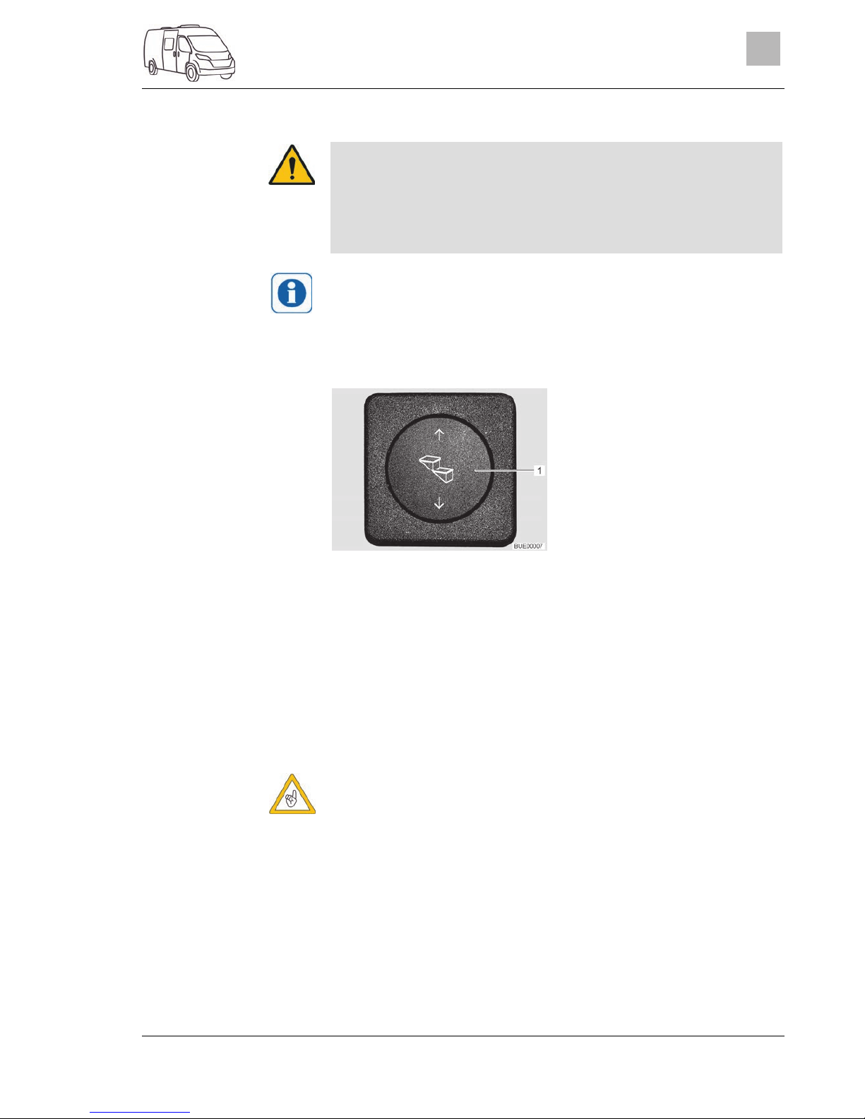
The rocker switch to operate the entrance step is installed on the bottom
right in the area of the sliding door.
If the entrance step has not been properly retracted and locked into
place, a warning tone is heard when the ignition is switched on.
The vehicles have a one-step, electrically extendable entrance step.
Fig. 1 Operating switch entrance
step
Before stepping on the entrance step, fully extend it.
Press the rocker switch (Fig. 1,1) down until the entrance step has extended completely.
Press the rocker switch (Fig. 1,1) up until the entrance step has retracted completely.
If the entrance step does not retract electrically due to a defect, it must be
pushed in by hand and secured against sliding out.
The entrance step may only be moved by hand when the drive rods
have been released.
Extending:
Retracting:
Emer
g
ency operation
Page 22

Before the journey
22
2999828 - 05/18 - EHG-0012-00EN
3
Fig. 2 Drive rod (entrance step) Fig. 3 Fixing clamp (entrance step)
On the bottom of the entrance step, pull off both locking clips (Fig. 2,2)
on the drive rods (Fig. 2,1).
Release both drive rods from the retaining bolts.
Connect drive rods with each other (e.g. with string, rubber ring). Such
you prevent the drive rods from slipping into the housing.
By hand, push the entrance step in as far as it will go.
Secure the entrance step against sliding out using the included fixing
clamp (Fig. 3,1).
Contact a dealer or service centre.
3.5 Removable partition wall
Insert the removable partition wall before commencing your journey.
The partition wall protects against objects that can be thrown through
the vehicle from the rear area.
The removable partition wall also serves as access assistance to the rear
bed.
Fig. 4 Partition wall
Page 23

Before the journey
2999828 - 05/18 - EHG-0012-00EN
23
3
3.6 Flat screen
Before commencing the journey, store the flat screen securely.
3.7 Gas regulator
Operating gas-operated appliances during the journey is permitted
only if the gas system has the relevant equipment. The hose break
guard and crash sensor prevent an escape of gas in the event of an
accident.
Depending on the equipment, different gas regulators can be installed in the
vehicle.
If a gas regulator other than one of those listed below is installed in the vehicle, the regulator tap on the gas bottle and the gas isolator taps must be
closed during the journey.
Fig. 5 Gas regulator (MonoCon-
trol)
Fig. 6 Gas regulator (DuoControl)
If a gas regulator with a crash sensor (Fig. 5,2 and Fig. 6,2) and hose break
guard (Fig. 5,1 and Fig. 6,1) is installed in the vehicle:
The regulator tap on the gas bottle and the "Heater" gas isolator tap may remain open during the journey. Gas-operated appliances may be on during
the journey.
The design details of the MonoControl (Fig. 5) and DuoControl (Fig. 6) gas
regulators can vary (straight or angled).
If in doubt, get the relevant information from authorised dealers or service centres.
Gas regulator with crash
sensor and hose break
g
uard
Page 24

Before the journey
24
2999828 - 05/18 - EHG-0012-00EN
3
3.8 Snow chains
Only mount snow chains if there is a clearance of at least 50 mm between the tyres and the vehicle body.
When using snow chains, the tyres, wheel suspension and steering are
subjected to an additional load. When using snow chains, drive slowly
(maximum speed 50 km/h) and only on streets which are completely
covered with snow. Otherwise the vehicle could be damaged.
Observe the fitting instructions issued by the manufacturer of the snow
chains.
Do not fit snow chains on alloy wheel rims.
The use of snow chains is subject to the legal regulations of the individual
countries.
Always mount snow chains to the drive wheels.
After a few metres, check the tension of the snow chains.
3.9 Road safety
Check tyre pressure before a journey or every 2 weeks. Wrong tyre
pressure causes excessive wear and can lead to damage or even to
tyre burst. You can lose control of the vehicle (see section 13.6).
Before commencing the journey, work through the checklist:
No. Checks Checked
Base vehicle
All vehicle documents are on board
Tyres in proper condition and tyre pressure correct
Vehicle lighting, brake lights and reversing lights function
Oil levels for engine, gearbox and power steering controlled
Coolant and fluid for windscreen washers filled up
Brakes function
Brakes react evenly
When braking, the vehicle remains in the lane
Housing body, outside
Awning completely retracted
Roof free of snow and ice (in winter)
External connections and lines disconnected and stored away
External supports removed
Wheel chocks removed and stored away
Entrance step retracted (observe warning tone)
External flaps closed and locked
Sliding door and rear door closed
Awning light switched off
Overall height of the vehicle including roof rack when loaded
measured and noted. Keep the height information close at
hand in the driver's cabin
Page 25

Before the journey
2999828 - 05/18 - EHG-0012-00EN
25
3
No. Checks Checked
Housing body, inside
Windows and skylights closed and locked
Television securely stored
Television antenna retracted (if one is built in)
Loose parts stored away or fixed in position
Open storage spaces empty
Sink cover closed
Refrigerator door secured
Refrigerator set to 12 V operation
All drawers and flaps closed
Living area doors and sliding doors secured
Partition wall fitted between the bedding boxes
Children's seats mounted to seats with three-point safety belts
Only forward-facing child restraint systems are per-
mitted.
Swivel seat locking device for driver's seat and front passenger's seat locked
Shades in the driver's cabin opened and secured
Gas system
Gas bottles firmly fixed in the gas bottle compartment so that
they are unable to turn
If the gas bottles are not connected to the gas tube, always
place the protective cap on top
Regulator tap on the gas bottle and gas isolator taps are
closed
When there is a MonoControl / DuoControl regulat-
ing system: When heating is required during travel
the gas isolator tap "Heater" and the regulator tap
can remain open.
Electrical system
Check the battery voltage of the starter and living area battery
(see chapter 8). If the panel indicates that the battery voltage
is too low, the respective battery will need to be recharged.
Observe the notes and instructions in chapter 8
Commence journey with fully charged starter and
living area batteries.
Page 26

Before the journey
26
2999828 - 05/18 - EHG-0012-00EN
3
Page 27

During the journey
2999828 - 05/18 - EHG-0012-00EN
27
4
4 During the journey
Chapter overview
This chapter contains instructions on how to drive the motorhome.
4.1 Driving the motorhome
The base vehicle is a commercial vehicle (small truck). Adjust your
driving technique accordingly.
Before commencing the journey and after short interruptions of the
journey, ensure that the entrance step is completely retracted.
When you start the engine, warning signals such as "entrance step
extended" can sound. Under certain conditions (a cold start in winter)
after the engine is started it can take up to 15 seconds for these warning signals to sound.
A seat belt is fitted for each seat which is permitted for travel. Please
keep your seat belt fastened during the journey.
Never open your seat belts when travelling.
Passengers must remain in the seats provided.
The doors must remain locked.
Avoid braking with a jerk.
If a navigation system is used, only change the destination when the
vehicle is stationary. Drive to a car park or stop in a safe area when
changing the destination.
Do not play DVDs using the monitor of the navigation system during
the journey.
Drive slowly on poor roads.
If an accident occurs as a result of these instructions not being observed, the manufacturer will not be responsible for damages caused.
The safety measures stipulated in chapter 2 have to be observed.
4.2 Driving speed
The vehicle is equipped with a powerful engine. This means there are
sufficient reserves in difficult traffic situations. This high power enables
a high maximum speed and requires above-average driving ability.
The vehicle provides a large contact surface for wind. A sudden cross-
wind can be especially dangerous.
Uneven or one-sided loading affects road performance.
Driving on unknown streets, you may encounter hazardous road con-
ditions and unexpected driving situations. Therefore, in the interest of
safety, make sure your driving speed is appropriate to any given driving situation and environment.
Adhere to the national legal speed limits.
Page 28

During the journey
28
2999828 - 05/18 - EHG-0012-00EN
4
4.3 Brakes
Have defects on the braking system immediately remedied by an au-
thorised specialist workshop.
Before each journey, check by means of a braking test:
Do the brakes function?
Do the brakes react evenly?
Does the vehicle remain in the lane when braking?
4.4 Seat belts
4.4.1 General
The vehicle is equipped with seat belts in the living area on the seats for
which seat belts are compulsory by law. National regulations apply to fastening of seat belts.
Fasten your seat belts before the beginning of the journey and keep
them fastened during the journey.
Do not damage or trap belts. Have damaged seat belts changed by an
authorised specialist workshop.
Do not alter the belt fixing devices, automatic seat belt winders and
the seatbelt locks.
Only use one seat belt for one adult person.
Do not belt in objects together with persons.
Seat belts are not sufficient for persons who are less than 150 cm tall.
In these cases use additional restraining devices. Observe test certificate.
Only attach the child restraint system to seats that are specified for
this purpose. Only forward-facing child restraint systems are permitted.
After an accident, replace the seat belts (have it replaced).
During the journey, do not tilt the backrest too far backwards. Other-
wise the functionality of the seat belt is no longer guaranteed.
4.4.2 Fastening the seat belts correctly
Do not twist the belt. The belt must be positioned smoothly against the
body.
When fastening the seat belt, adopt the correct sitting position.
The seat belt is correctly fastened when the lap belt passes below your
stomach and across the hip bone. The shoulder belt must pass across the
chest and shoulder (not across your neck). The belt must always be taut
against your body. Any bulky or padded clothing should therefore be removed before you start your journey.
Before each journey
Page 29

During the journey
2999828 - 05/18 - EHG-0012-00EN
29
4
4.5 ISOFIX child safety seat mounting system
Fig. 7 ISOFIX child safety seat
mounting system
If the vehicle is equipped with the ISOFIX child safety seat mounting system,
the vehicle seats suitable for it are marked with the ISOFIX symbol. These
vehicle seats have retaining clips (Fig. 7,1). Use child restraint system suitable for ISOFIX. The child restraint systems possess connectors which are
latched to the retaining brackets of the vehicle seat.
The bench with the special equipment ISOFIX child safety seat mounting
system is suitable for child seats with ISOFIX system, which are specially
authorised for this vehicle type according to the standard ECE-R 44.
Child restraint systems of the groups 0, 0+, and 1 with ISOFIX child safety
seat mounting system can be fastened at the ISOFIX anchorage points on
the bench.
Push the connectors of the child seat into the ISOFIX anchorage points
until they engage audibly.
By pulling the child seat, check whether both sides have engaged correctly.
Also observe the instruction manual of the child restraint system manufacturer.
4.6 Driver's seat and front passenger's seat
Before commencing the journey, rotate all swivel seats in the direction
of travel and lock in position.
The seats must remain fixed in position during the journey and are not
to be rotated.
The driver's seat and the front passenger's seat are part of the base vehicle.
The adjustment of the seats is described in the operating manual of the
base vehicle.
4.7 Headrests
Before commencing the journey, adjust the headrests so that the back of the
head is supported at approximately ear height.
Fastening a child seat
Page 30

During the journey
30
2999828 - 05/18 - EHG-0012-00EN
4
4.8 Seating arrangement
During the journey, persons are only to sit on the permitted seats. The
authorised number of seats is stipulated in the vehicle documents.
Seat belts must be worn by all passengers.
Seats which may be used during travel are equipped with a seat belt.
4.9 Filling up with diesel
All gas-operated devices (heater, cooker) must be switched off for re-
fuelling, on ferries or in the garage. Danger of explosion!
The fuel filler neck is situated on the exterior of the vehicle, at the front left.
Page 31

Pitching the Motorcaravan
2999828 - 05/18 - EHG-0012-00EN
31
5
5 Pitching the Motorcaravan
Chapter overview
This chapter contains instructions on how to pitch the vehicle.
Pitch the vehicle so that it is as horizontal as possible. Use ramps where
necessary. Otherwise, the water from the shower tray will not be able to
drain properly.
Secure the vehicle to prevent it from rolling.
Animals (especially mice) can cause great damage to the interior of the
vehicle. To prevent this from happening, regularly check the vehicle for
damages or animal traces after pitching.
5.1 Handbrake
Firmly apply the handbrake when parking the vehicle.
5.2 Entrance step
In order to exit the vehicle, first fully extend the entrance step.
5.3 Ramps
Ramps are not included in the scope of delivery. Different models are
available at the accessories shop.
To enable the vehicle to be parked on the level, ramps can be used for
height compensation when the vehicle is parked on a hill or on uneven
ground.
5.4 230 V connection
The vehicle can be connected to a 230 V power supply (see chapter 8).
5.5 Refrigerator
Continuous operation of the refrigerator without external 230 V power
supply can discharge the living area battery.
Check the charging condition of the living area battery on the panel. If possible, connect external 230 V power supply.
Page 32

Pitching the Motorcaravan
32
2999828 - 05/18 - EHG-0012-00EN
5
Page 33

Living
2999828 - 05/18 - EHG-0012-00EN
33
6
6 Living
Chapter overview
This chapter contains instructions about living in the vehicle.
6.1 Doors
Only drive with locked doors.
Locking the doors can prevent them from opening of their own accord,
e.g. during an accident.
Locked doors also prevent forced entry, e.g. when waiting at traffic
lights. However, in an emergency, locked doors make it more difficult for
helpers to enter the vehicle.
When leaving the vehicle, always lock the doors.
The locks on the vehicle doors are a part of the base vehicle. The opening and closing of the vehicle doors is described in the instruction manual of the base vehicle.
6.1.1 Insect screen on the sliding door, extendable
Open the insect screen completely before closing the sliding door.
Fig. 8 Insect screen
Pull out the insect screen completely by the bar (Fig. 8,1).
Push the insect screen into its initial position by the bar (Fig. 8,1).
6.1.2 Rear doors
If the rear doors are opened too far, add-on parts on the vehicle may get
damaged. The opening angle of the rear doors was limited for this reason at the factory. When releasing this limitation: continue opening the
rear door only carefully and ensure that the rear door does not hit any
add-on parts.
Closing:
Opening:
Page 34

Living
34
2999828 - 05/18 - EHG-0012-00EN
6
The opening angle of both rear doors is limited to approx. 90° at the factory.
This limitation can be released if necessary.
Fig. 9 Push button to release the
limitation
Open the rear door (Fig. 9,2) as far as it will go.
Press the push button (Fig. 9,1), hold rear door and continue opening
carefully.
6.2 External flaps
Before commencing the journey, close all external flaps and lock them.
To open and close the external flap, open or close all locks that are fitted
to the external flap.
When leaving the vehicle, close all external flaps.
The external flaps fitted to the vehicle are all fitted with identical locking cylinders. Therefore, all locks can be opened with a single key.
6.3 Ventilation
The oxygen in the vehicle interior is used up by breathing and the use
of gas operated appliances. That is why the used air must be replaced
permanently. For this purpose, forced ventilation options (e.g. skylights with forced ventilation) are fitted to the vehicle. Never cover or
block forced ventilations from the inside or outside with objects such
as e.g. a winter mat. Keep forced ventilations clear of snow and
leaves. There is a danger of suffocation due to increased CO2 levels.
Although sufficient ventilation is provided, in certain weather conditions,
condensation can form on metal objects (e.g. screwed connections in
the floor).
Additional cold spots can occur at thermal "bridges" (e.g. skylight edges,
filler necks, flaps, etc.).
Releasing the opening
angle limitation:
Page 35

Living
2999828 - 05/18 - EHG-0012-00EN
35
6
Ensure that there is a continuous exchange of air by providing frequent and
efficient ventilation. This is the only method for ensuring that condensation is
not formed during cool weather. During the colder season, a pleasant living
climate is created if heating output, air distribution and ventilation are synchronised. To avoid draft close the air outlet nozzles on the dashboard and
set the air distribution of the base vehicle to air circulation. If the vehicle is
laid up for a longer period, occasionally ventilate it well, especially in summer as heat accumulation can occur.
6.4 Windows
Do not keep blinds closed over a longer period of time as that can cause
increased material wear.
If the blind is completely closed, exposure to direct sunlight can cause
heat to accumulate between the blind and the glass window. The window could be damaged. For that reason, close the blind only 2/3 of the
way in direct sunlight.
Before commencing the journey, close the windows.
Depending on the weather, close the windows far enough to prevent
moisture from entering.
To open and close the hinged window, open or close all catch levers
which are fitted to the hinged window.
When leaving the vehicle, always close the windows.
In extreme weather conditions or if the temperature fluctuates strongly, a
light condensation film can form on the double-glazed acrylic glass. The
glass is designed in such a way that condensation can evaporate when
the external temperature increases. There is no danger of the doubleglazed acrylic glass being damaged by condensation.
6.4.1 Hinged window
If windows with automatic hinges are fitted, open the window fully in order to release the lock. If the locking device is not released and the window is closed nevertheless, there is the danger of the window breaking
due to the massive counter-pressure.
When opening the hinged windows, ensure that there are no torsional
forces. Open and close the hinged windows evenly.
Condensation
Page 36

Living
36
2999828 - 05/18 - EHG-0012-00EN
6
Fig. 10 Catch lever in "closed" posi-
tion
Fig. 11 Hinged window with auto-
matic hinges, open
Turn the catch lever (Fig. 10,3) a quarter turn towards the centre of the
window.
Open hinged window half up to the required position. Allow the hinged
window to engage automatically with the automatic hinge (Fig. 11,1).
The hinged window remains locked in the required position.
Open the hinged window as wide as necessary until the latch releases.
Close the hinged window.
Turn the catch lever (Fig. 10,3) a quarter turn towards the window
frame. The locking catch (Fig. 10,1) is located on the inside of the window catch (Fig. 10,2).
Fig. 12 Catch lever in "continuous
ventilation" position
With the catch lever, the hinged window can be placed in two positions:
"Continuous ventilation" (Fig. 12)
"Firmly closed" (Fig. 10).
To place the hinged window into the "continuous ventilation" position:
Turn the catch lever (Fig. 12,3) a quarter turn towards the centre of the
window.
Slightly open the hinged window outwards.
Turn the catch lever a quarter turn towards the window frame. The locking catch (Fig. 12,1) has to be moved into the recess of window catch
(Fig. 12,2).
During the journey, the hinged window may not be in "continuous ventilation" position.
Opening:
Closing:
Continuous ventilation
Page 37

Living
2999828 - 05/18 - EHG-0012-00EN
37
6
If it rains, the "continuous ventilation" hinged window position could lead to
splashing water penetrating the living area. Therefore, close the hinged
windows completely.
6.4.2 Roman shade and insect screen
The windows are fitted with a Roman shade and an insect screen. Roman
shade and insect screen are fixed to each other.
Fig. 13 Roman shade and insect
screen (hinged window)
The Roman shade is located in the upper window frame.
Hold the Roman shade in the centre of the bottom rod (Fig. 13,2) and
carefully draw it downwards.
Hold the bottom rod (Fig. 13,2) of the Roman shade in the centre and
carefully slide the Roman shade upwards.
The insect screen is located in the upper window frame.
Pull insect screen at the handle (Fig. 13,1) downwards.
Move the insect screen continuously.
If the insect screen is not drawn fully to the bottom, the Roman shade can
be stretched up to the end of the side window frame.
Move insect screen at the handle (Fig. 13,1) fully upwards.
Roman shade
Closing:
Opening:
Insect screen
Closing:
Opening:
Page 38

Living
38
2999828 - 05/18 - EHG-0012-00EN
6
6.4.3 Cabin black-out shade
Open cabin black-out shade before commencing the journey.
Fig. 14 Cabin black-out shade on
side pane
Fig. 15 Cabin black-out shade on
windscreen
Take cabin black-out shade out of the storage compartment above the
driver's cabin.
Fasten cabin black-out shade on one side of the driver's cabin. In order
to do this, fasten two snap fasteners (Fig. 14,2) behind the side pane, on
the B column.
Guide loop (Fig. 14,1) over the handle above the side pane and fasten
with snap fasteners.
Push pockets (Fig. 15,1) of cabin black-out shade over the two sun visors.
On the other side of the driver's cabin: also fasten the cabin black-out
shade with loop on the handle and snap fasteners on the B column.
Release the cabin black-out shade at all fastening points.
Store cabin black-out shade in the storage compartment above the driver's cabin.
6.5 Skylights
Skylights with and without forced ventilation are installed in the vehicle. The
smaller skylights in the living area and in the bathroom are equipped with
forced ventilation.
The apertures for forced ventilation must always be kept open. Never
cover or block forced ventilations with objects such as e.g. a winter
mat. Keep forced ventilations clear of snow and leaves.
Do not keep blinds closed over a longer period of time as that can cause
increased material wear.
If the blind or the Roman shade is completely closed, exposure to direct
sunlight can cause heat to accumulate between the blind/the Roman
shade and the skylight. The skylight could be damaged. For that reason,
close the blind/Roman shade only 2/3 of the way in direct sunlight. Open
the skylight slightly or move it to ventilation position.
Closing:
Opening:
Page 39

Living
2999828 - 05/18 - EHG-0012-00EN
39
6
Depending on the weather, close the skylights far enough to prevent
moisture from entering.
Do not climb on the skylights.
Before commencing the journey, close the skylights.
Before commencing the journey, check that the skylights are closed and
locked.
When leaving the vehicle, always close the skylights.
The upholstery will fade over time, if it is exposed to sunlight. If the temperature within the vehicle rises rapidly as well, the colour will change at
an accelerated rate.
Therefore, we recommend closing the shades on the skylights of the
parked vehicle by 2/3 when there is strong sunlight.
6.5.1 Skylight with snap latch
Fig. 16 Skylight with snap latch
The skylight can be pushed upwards either from one side or from both
sides.
Pull on the handle (Fig. 16,3).
Fold insect screen (Fig. 16,4) downward.
Push the snap latch (Fig. 16,1) towards the inside of the skylight. At the
same time use the handle (Fig. 16,2) to press the skylight upwards.
Swing insect screen (Fig. 16,4) upwards until it latches in place.
Pull on the handle (Fig. 16,3).
Fold insect screen (Fig. 16,4) downward.
Using both handles (Fig. 16,2), pull down the skylight with force until the
two snap latches (Fig. 16,1) lock into place.
Swing insect screen (Fig. 16,4) upwards until it latches in place.
Opening:
Closing:
Page 40

Living
40
2999828 - 05/18 - EHG-0012-00EN
6
6.5.2 Heki skylight
Fig. 17 Safety knob (Heki skylight) Fig. 18 Guide (Heki skylight)
The Heki skylight is opened on one side only.
Press the safety knob (Fig. 17,2) and pull the bar (Fig. 17,1) down with
both hands.
Pull the bar (Fig. 18,1) in the guides (Fig. 18,2) to the rearmost position
(Fig. 18,3).
Use both hands to push the bar (Fig. 18,1) slightly upwards.
Push the bar back in the guides.
Push the bar upwards with both hands until it is above the safety knob
(Fig. 17,2).
Fig. 19 Guide (ventilation position) Fig. 20 Lock (ventilation position)
The Heki skylight can be put in two ventilation positions: Bad weather position (Fig. 19,1) and central position (Fig. 19,2). Depending on the model, the
skylight can be locked in the central position with the latch (Fig. 20,1).
Press the safety knob (Fig. 17,2) and pull the bar (Fig. 17,1) down with
both hands.
Pull the bar in the guides (Fig. 18,2) to the desired position.
Push the bar slightly upwards and into the selected guide (Fig. 19,1
or 2) and lock if necessary.
To close and open the Roman shade:
Pull out Roman shade at the handle and release in the required position.
The Roman shade will stay in that position.
Slowly push the Roman shade at the handle to its initial position.
Opening:
Closing:
Ventilation position
Roman shade
Closing:
Opening:
Page 41

Living
2999828 - 05/18 - EHG-0012-00EN
41
6
To close and open the insect screen:
Pull the insect screen by the handle to the opposite handle of the Roman shade.
Press the rear part of the handle of the insect screen. The latch is released.
Use handle to return the insect screen slowly to its initial position.
6.5.3 Wind-up skylight
Fig. 21 Wind-up skylight Fig. 22 Hand crank
The wind-up skylight can be opened using the hand crank. The hand crank
is folded out (Fig. 22,2) for opening and closing. The hand crank is folded in
(Fig. 22,1) when in resting position.
Rotate the hand crank (Fig. 21,2) until a resistance can be felt.
Rotate the hand crank until the wind-up skylight is closed. The wind-up
skylight can be locked after rotating two or three more times.
Check the locking mechanism. To do so, press your hand against the
acrylic glass.
The Roman shade can be closed in any position, as desired. If the Roman
shade is locked with the insect screen, the insect screen is also moved
along on closing the Roman shade.
Pull the handle of the Roman shade (Fig. 21,3) in the direction of the arrow and release it in the desired position. The Roman shade will stay in
that position.
Slowly push the Roman shade at the handle to its initial position.
If the insect screen is locked with the Roman shade, the Roman shade is
also moved along on closing the insect screen.
Use the handle to pull the insect screen (Fig. 21,1) in the direction of the
arrow to the opposite handle of the Roman shade (Fig. 21,3) and allow it
to engage.
Press the handle of the insect screen (Fig. 21,1) at the back upwards
and detach the insect screen from the Roman shade (Fig. 21,3).
Use handle to return the insect screen slowly to its initial position.
Insect screen
Closing:
Opening:
Opening:
Closing:
Roman shade
Closing:
Opening:
Insect screen
Closing:
Opening:
Page 42

Living
42
2999828 - 05/18 - EHG-0012-00EN
6
6.6 Tables
6.6.1 Suspension table with separable support leg
The maximum permissible load on the swung-out table-top extension is
3 kg.
Fig. 23 Suspension table with sep-
arable support leg
The suspension table size can be enlarged by swinging out a table top extension.
Pull the knob (Fig. 23,2) of the lock down and swing out the table top extension (Fig. 23,1).
Swing the table top extension (Fig. 23,1) under the table top (Fig. 23,6)
until the lock latches in place audibly.
The suspension table's separable support leg enables it to be used as a bed
foundation.
Lift the front of the table top (Fig. 23,6) by approx. 45°.
Pull out the lower part of the support leg (Fig. 23,4) down and lay aside.
Remove the table top from the upper retainer.
Hook the table top at a 45° angle to the supports into the lower retainer
(Fig. 23,3) and place on the floor with the upper part of the support leg
(Fig. 23,5).
Extending:
Reducing size:
Conversion to bed
foundation:
Page 43

Living
2999828 - 05/18 - EHG-0012-00EN
43
6
6.6.2 Folding worktop
The folding worktop is designed only for minimal loads (e.g. kitchen
utensils). Do not use the folding worktop as a repository for heavy objects.
1 Magnet
2 Worktop
3 Holder
Fig. 24 Folding worktop (driving posi-
tion)
To increase the size of the kitchen work surface, a folding worktop can be
folded out at the side of the kitchen counter.
Fold worktop (Fig. 24,2) up.
Lock worktop. In order to do this, swivel out the holder (Fig. 24,3).
Swivel holder (Fig. 24,3) away.
Fold worktop (Fig. 24,2) down.
A magnet (Fig. 24,1) holds the worktop in driving position.
6.7 PVC-floor covering
Gas pipes and electric lines are laid in the floor. Never drill holes in
the floor or insert any screws. That could cause a gas explosion, an
electrical shock or a short circuit due to damage to a cable.
Shoes with pointed heels can leave permanent impressions in the PVCfloor covering. Never wear shoes with pointed heels in the vehicle.
Rubber mats or long exposure to ketchup, carrot juice, ink, blood or lipstick can discolour the PVC-floor covering. If possible, remove stains
from the floor immediately.
6.8 Lamps
The light switches have different layouts according to the model. The
light switches are located either in the entrance area, directly on the corresponding lamp or next to the lamp, e.g. in the vicinity of the seating
group.
The light switches for the lamps on the ceiling of the living area are installed
in the rear area and in the entrance area (at the sliding door).
Bringing the folding worktop
into the work position:
Bringing the folding worktop
into the travel position:
Page 44

Living
44
2999828 - 05/18 - EHG-0012-00EN
6
6.8.1 Lighting system and USB socket
Bulbs and light fittings can be extremely hot.
Allow the light bulbs and lamp holders to cool down before touching
them.
If the light is switched on or still hot, there must always be a safety dis-
tance of at least 30 cm between stores or curtains and flammable objects. Fire hazard!
Fig. 25 Spotlight
Turn housing (Fig. 25,2) of the spotlight to the desired direction.
The housing can be turned in following directions:
To the left and to the right
Up and down
Turn holder (Fig. 25,1) through approx. 45°.
Shift spotlight along the rail system to the desired position.
Turn holder (Fig. 25,1) through 90°.
Remove spotlight from rail.
Fig. 26 Fluorescent tube
Insert both brackets (Fig. 26,1) into the rail (Fig. 26,3). In order to do
this, turn bracket through 90°.
Plug lamp body (Fig. 26,2) into one of the brackets.
Shift the other bracket up to the lamp body until a firm connection has
been made.
Turn lamp body handle (Fig. 26,2) until the desired lighting effect is
achieved.
Turning spotlight:
Shifting spotlight:
Removing spotlight:
Inserting fluorescent tube:
Turning fluorescent tube:
Page 45

Living
2999828 - 05/18 - EHG-0012-00EN
45
6
Release and shift one of the brackets away from the lamp body.
Remove lamp body.
Turn both brackets through 90° and remove from rail.
Fig. 27 USB socket element
The USB socket element (Fig. 27,1) can be inserted, turned, and removed in
the same way as the spotlight.
6.8.2 Lamp in the rear area
A lamp is installed on the side in the rear area.
Fig. 28 Lamp, rear area
Press the transparent cover of the lamp on the side.
Removing fluorescent tube:
Switching on/off:
Page 46
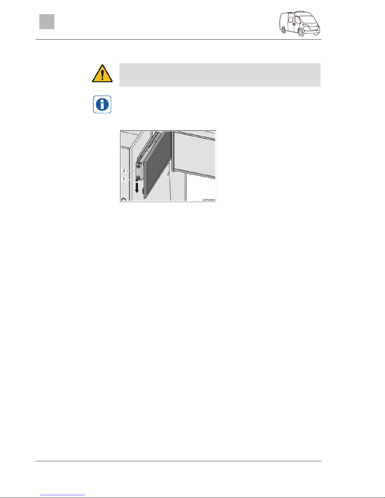
Living
46
2999828 - 05/18 - EHG-0012-00EN
6
6.9 TV unit
Before commencing the journey, store the flat screen securely.
The information about the operation of the TV unit can be obtained in the
manufacturer's instruction manual.
The flat screen is attached to a pull-out above the headrests of the bench.
Fig. 29 Pull-out with flat screen
Press catch spring (Fig. 29,1) downwards and pull pull-out (Fig. 29,2)
with flat screen out horizontally towards the centre of the vehicle.
Rotate the flat screen into the desired position.
The flat screen can be turned such that it can also be watched from the
rear area.
Return the flat screen into its initial position.
Push the pull-out (Fig. 29,2) with flat screen horizontally as far as it will
go. The catch spring (Fig. 29,1) engages audibly.
Bringing the flat screen into
the television position:
Bringing the flat screen into
the driving position:
Page 47

Living
2999828 - 05/18 - EHG-0012-00EN
47
6
6.10 Beds
6.10.1 Transverse rear bed
The maximum load of the rear bed is 200 kg.
But in particular with regard to small children less than 6 years of age,
users should ensure that they cannot fall out of the bed.
Fig. 30 Rear bed (transport position) Fig. 31 Rear bed (converted for
sleeping)
Release retaining belts (Fig. 30,1).
Fold bed base (Fig. 30,2) out and set down on bars (Fig. 30,4) above
the central aisle.
Distribute the cushions (Fig. 30,3) on the lying surface as shown
in Fig. 31.
Stack the cushions and the bed base on the left-hand bottom cupboard
as shown in Fig. 30.
Secure the cushions and the bed base with retaining belts (Fig. 30,1).
6.10.2 Longitudinal rear beds
The centre bed base can be folded up or taken out in order to transport
larger objects (e.g. bicycles).
The windows of the rear doors are equipped with a fall out protection
(Fig. 32,1). The garage door can always be unlocked from the interior
via the opening (Fig. 33,2).
Fig. 32 Fall out protection (longitudi-
nal rear bed)
Conversion for sleeping:
Conversion after sleeping:
Page 48

Living
48
2999828 - 05/18 - EHG-0012-00EN
6
Fold bed base down or insert bed base.
Distribute the cushions on the lying surface.
Fig. 33 After the conversion (variant
with 3 cushions)
Fig. 34 After the conversion (variant
with 4 cushions)
Stack the cushions on the left-hand bottom cupboard.
Fold the folding bed base up or remove the removable bed base.
Secure the cushions and the bed base with retaining belts.
Fig. 35 Transport position (folding
bed base)
Fig. 36 Transport position (remova-
ble bed base)
Conversion for sleeping:
Conversion for transporting
larger objects:
Page 49

Living
2999828 - 05/18 - EHG-0012-00EN
49
6
6.10.3 Bunk bed in the rear
Only use the bunk bed in the rear with fall out protection.
The bunk bed consists of 2 removable bed bases, 4 cushions, a fall out protection, and an attachable ladder.
The maximum permitted load on each bed base of the bunk bed is 100 kg.
Fig. 37 Bunk bed Fig. 38 Bunk bed with attached lad-
der
A ladder (Fig. 38) can be attached to the bunk bed to make the access to
the bunk bed easier.
Fig. 39 Bunk bed, converted into
seating group
The bunk bed can be converted into a seating group (Fig. 39). In order to do
this, set the bed bases down on the clamping rails upside down, and use the
cushions of the rear bed as backrests.
Page 50

Living
50
2999828 - 05/18 - EHG-0012-00EN
6
6.11 Converting seating group for sleeping
Fig. 40 Removable board on the
right-hand bedding box
Push both seats in the driver's cabin fully forwards.
Convert the table to a bed foundation (see section 6.6.1).
Remove additional removable board (Fig. 40,2) from the right-hand bedding box in the rear.
Fold footrest (Fig. 40,1) out on the removable board.
Fig. 41 During conversion Fig. 42 After conversion
Hook removable board (Fig. 41,1) in on the side of the bench and place
it on the table.
Place additional cushion (Fig. 42,1) on the lowered table as shown in
the image.
Page 51

Gas system
2999828 - 05/18 - EHG-0012-00EN
51
7
7 Gas system
Chapter overview
This chapter contains instructions regarding the gas system of the vehicle.
The operation of the gas operation appliances of the vehicle is described in
chapter 9.
7.1 General instructions
The operator of the gas system is responsible for the performance of
recurring inspections and for complying with the maintenance intervals.
Before commencing the journey, when leaving the vehicle or when
gas equipment is not in use, close all gas isolator taps and the main
regulator tap on the gas bottle.
All gas-operated devices (heater, cooker) must be switched off for re-
fuelling, on ferries or in the garage. Danger of explosion!
Do not use gas-operated devices in closed spaces (e.g. garages).
Danger of poisoning and suffocation!
Only have the gas system maintained, repaired or altered by an au-
thorised specialist workshop.
Have the gas system checked by an authorised specialist workshop
according to the national regulations before commissioning. This also
applies for not registered vehicles. For modifications to the gas system have the gas system immediately checked by an authorised specialist workshop.
The gas pressure regulator, the gas tubes, and the exhaust gas pipes
must also be inspected. The gas pressure regulator and the gas tubes
must be replaced observing the nationally defined deadlines (the latest after 10 years). The vehicle owner is responsible for seeing that
this is carried out.
In case of a defect of the gas system (gas odour, high gas consump-
tion) there is danger of explosion! Close regulator tap on the gas bottle immediately. Open doors and windows and ventilate well.
If the gas system is defective: Do not smoke; do not ignite any open
flames, and do not operate electric switches (light switches etc.).
Check the tightness of gas-conducting parts and lines with leakage
search spray. Do not check with an open flame.
Only the stipulated devices may be connected to internal connections.
Do not operate any device outside the vehicle if it is connected to an
internal connector.
Cooking is prohibited during the journey.
Before using the cooker make sure that there is sufficient ventilation.
Open a window or the skylight.
Do not use the gas cooker for heating purposes.
If there are several gas devices, each gas device must have its own
gas isolator tap. If individual gas devices are not in use, close the respective gas isolator tap.
Ignition safety valves must close within 1 minute after the gas flame
has extinguished. A clicking sound is audible. Check function from
time to time.
Page 52

Gas system
52
2999828 - 05/18 - EHG-0012-00EN
7
The built-in gas devices are exclusively meant for use with propane or
butane gas or a mixture of both. The gas pressure regulator as well as
all built-in gas devices are designed for a gas pressure of 30 mbar.
Propane gas is capable of gasification up to -42 °C, whereas butane
gas gasifies at 0 °C. Below these temperatures no gas pressure is
available. Butane gas is unsuitable for use in winter.
Due to its function and construction, the gas bottle compartment is a
space which is open to the exterior. Never cover or block up the
standard forced ventilations. Otherwise gas that is emitted can not be
diverted to the outside.
The gas bottle compartment must not be used as storage space.
Secure the gas bottle compartment against unauthorised access. To
do this, lock the compartment.
The regulator tap on the gas bottle must be accessible.
Only connect gas-operated devices (e.g. gas grill) which have been
designed for a gas pressure of 30 mbar.
The exhaust gas pipe must be fitted tightly to the heating system and
to the vent and must be sealed. The exhaust gas pipe must not show
any evidence of damage.
Exhaust fumes must be able to escape into the atmosphere unhin-
dered and fresh air must be able to enter unhindered. For this reason,
keep the exhaust pipe and intake openings clean and unobstructed
(e.g. free from snow and ice). For this reason, no snow walls or
aprons may lie against the vehicle.
7.2 Gas bottles
Handle full or emptied gas bottles outside the vehicle only with closed
regulator tap and attached protective cap.
Gas bottles are only to be transported within the designated gas bottle
compartment.
Place the gas bottles in vertical position in the gas bottle compart-
ment.
Fasten the gas bottles so that they are unable to turn or tilt.
Connect the gas tube to the gas bottle without tension.
If the gas bottles are not connected to the gas tube, always place the
protective cap on top.
Close the regulator tap on the gas bottle before the gas pressure reg-
ulator or gas tube are removed from the gas bottle.
Depending on the connection, unscrew the gas tube from the gas bot-
tle and screw it on the gas bottle again by hand or using an suitable
special spanner. The screw connection on the gas bottle generally
has a left-hand thread. Do not tighten too firmly.
Only use special gas pressure regulators with a safety valve designed
for vehicle use. Other gas pressure regulators are not permitted and
cannot meet the demanding requirements.
Use the gas pressure regulator defroster if the temperature falls below
5 °C.
Page 53

Gas system
2999828 - 05/18 - EHG-0012-00EN
53
7
Use only 11 kg or 5 kg gas bottles. Camping gas bottles with built-in
check valve (blue bottle with max. 2.5 or 3 kg content) are can be
used in exceptional cases with a safety valve.
Use the shortest possible tube lengths (150 cm max.) for external gas
bottles.
Never block the floor ventilation openings below the gas bottles.
The screw connections on the gas bottles generally have a left-hand
thread.
For gas-operated units the gas pressure must be reduced to 30 mbar.
Connect gas pressure regulator complete with safety valve directly to
bottle valve.
For filling and connecting the gas bottles in Europe the accessories
shops have corresponding Euro filling sets and Euro bottle sets.
Information available at the dealers or service centre.
The gas pressure regulator reduces the gas pressure in the gas bottle down
to the operating pressure of the gas devices.
The gas pressure regulator is permanently installed in the gas bottle compartment. The gas bottle is connected to the gas pressure regulator via a
high-pressure gas hose.
The high-pressure gas hoses and their connections are different in the various countries. The accessories shop offers the respective country-specific
models and adapters.
7.3 Gas pressure regulating system DuoControl CS
The regulating system and the hose lines shall be changed at the latest
10 years after manufacturing date. The operator is responsible for this.
Also read the manufacturer's instruction manual.
DuoControl CS is a safety gas pressure regulating system with automatic
switching for a two-bottle gas system and with crash sensor. The DuoControl regulating system automatically switches the gas supply from the primary bottle to the reserve bottle as soon as the primary bottle is either
empty or no longer ready for operation. The gas appliances may still continue operation. The DuoControl regulating system is suitable for all commercial gas bottles with liquefied gas (propane/butane) and a pressure of
0.6 bar to 16 bar.
The DuoControl regulating system ensures a constant gas pressure for the
gas-operated devices, no matter which gas bottle is supplying the gas.
In the event of an accident, the crash sensor in the DuoControl regulating
system will interrupt the gas flow.
The gas bottles are connected via high pressure hoses. A hose break guard
prevents gas leakage in the event of a damaged hose.
The operation of gas-operated devices during the journey is permitted in all
of Europe if the vehicle is equipped with a gas pressure regulating system
with crash sensor and high-pressure hoses with hose break guard.
Page 54

Gas system
54
2999828 - 05/18 - EHG-0012-00EN
7
Fig. 43 Gas bottles with DuoCon-
trol
Fig. 44 DuoControl regulating system
The DuoControl regulating system consists of a reversing valve (Fig. 43,4)
and a crash sensor (Fig. 43,5). The DuoControl regulating system is installed between the gas tubes (Fig. 43,3) with hose break guard (Fig. 43,1).
The knob (Fig. 44,1) on the reversing valve is used to select which of the
gas bottles is to be used as primary bottle and which is to be used as reserve bottle.
The status of the gas supply is indicated in the inspection window
(Fig. 44,2):
Green: Gas is taken out of the primary bottle.
Red: Gas is taken out of the reserve bottle.
The operation with only one gas bottle is allowed but in this case the open
connection must be closed with a blind cover (Fig. 44,4).
The crash sensor blocks the gas supply in the event of a significant impact
(e.g. accident). The crash sensor is put into operation with the green reset
button (Fig. 44,3).
The hose break guard (Fig. 43,1) blocks the gas flow if the connected hose
breaks. The hose break guard must be activated by pressing the green button.
The DuoControl regulating system can be heated (defroster). If winter operation is set at the operating unit, the DuoControl regulating system will be
heated automatically. Thus, faults of the gas system due to frost in winter
are prevented.
1 Yellow indicator lamp, defroster
2 Winter operation position
3 OFF position
4 Summer operation position
5 Red indicator lamp, primary bottle
empty
6 Green indicator lamp, supply from
primary bottle
7 Rocker switch
Fig. 45 Operating unit (DuoControl)
Construction of the unit
Crash sensor
Hose break
g
uard
Defroste
r
Page 55
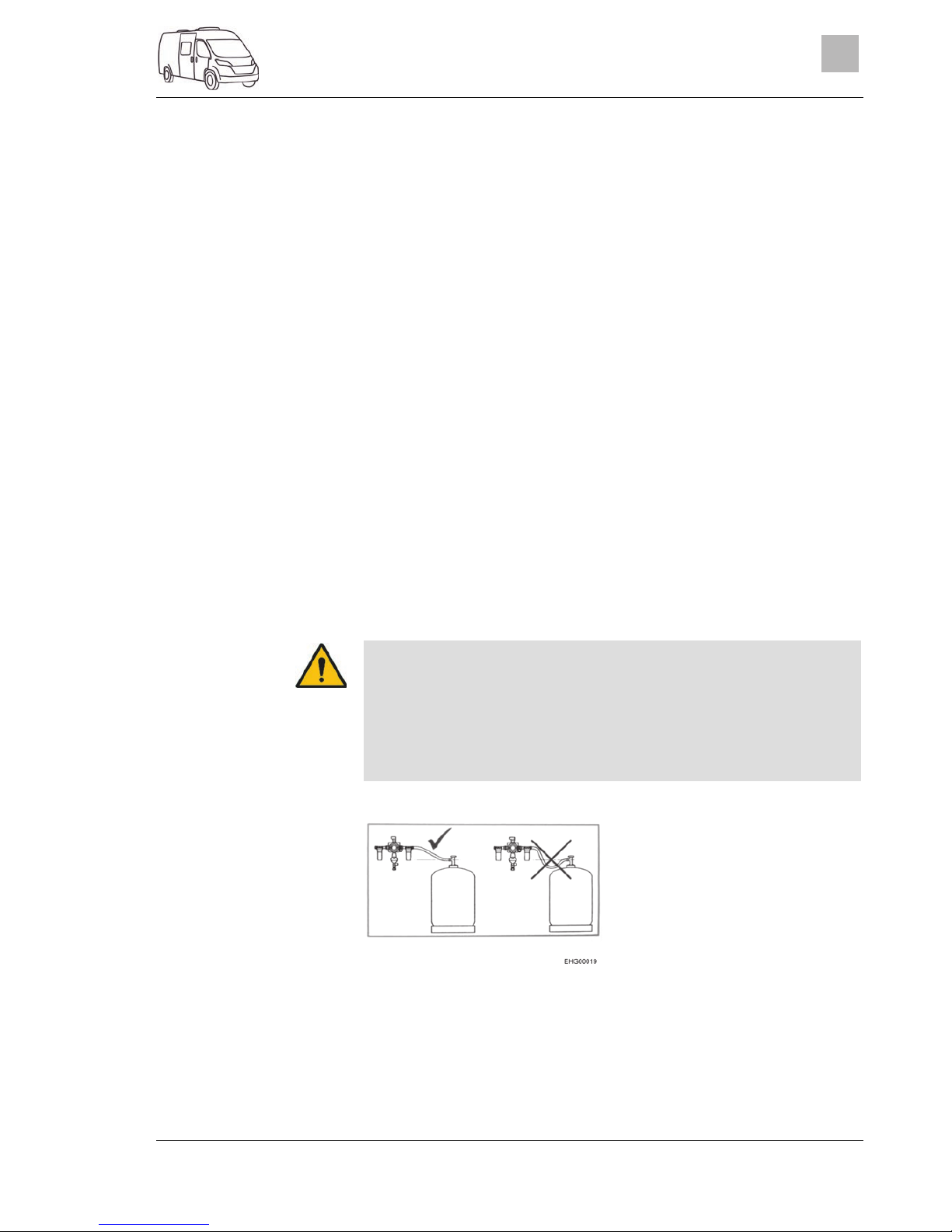
Gas system
2999828 - 05/18 - EHG-0012-00EN
55
7
At the operating unit (Fig. 45), the gas supply via the DuoControl regulating
system is switched on and off. The regulator taps (Fig. 43,2) of the gas bottles and the gas isolator taps of the devices must be opened manually.
Summer and winter operation are switched with the rocker switch (Fig. 45,7)
on the operating unit.
The two indicator lamps on the operating unit indicate the level of the primary bottle. When the green indicator lamp (Fig. 45,6) is lit, the primary bottle is sufficiently filled. When the red indicator lamp (Fig. 45,5) illuminates,
the primary bottle is empty. In this case, the reserve bottle is used for the
gas supply.
Connect the gas bottles.
Use the knob (Fig. 44,1) on the reversing valve to select the gas bottle
which is to be the primary source of gas (primary bottle). Always turn the
knob as far as it will go.
Open regulator taps (Fig. 43,2) on the gas bottles.
Press the green button of the hose break guard (Fig. 43,1). The green
marking is shown in the inspection window (Fig. 44,2).
Switch on the DuoControl regulating system at the operating unit
(Fig. 45). To do so, set the rocker switch (Fig. 45,7) to winter operation
(Fig. 45,2) or to summer operation (Fig. 45,4). The yellow defroster indicator lamp (Fig. 45,1) is lit when winter operation is selected.
Set the rocker switch (Fig. 45,7) to the OFF position (Fig. 45,3). The indicator lamps go out.
Close regulator taps (Fig. 43,2) on the gas bottles.
When changing gas bottles, do not smoke or create any open fire.
When you have changed the gas bottle, check whether gas escapes
at the connection points and unions. Use a leakage search spray to
spray the relevant connection point or union. These agents are
available at the accessories shop.
Connect gas pipe such that it rises from the gas bottle towards the
regulating system (see Fig. 46).
Fig. 46 Correct connection of the gas
bottle
If the green indicator lamp (Fig. 45,6) goes out during operation and the red
indicator lamp (Fig. 45,5) lights up, the primary bottle is empty and must be
changed. The red marking is shown in the inspection window (Fig. 44,2).
The reserve bottle continues supplying the gas appliances with gas.
Operating unit
Putting into operation:
Switching on
summer/winter operation:
Switching off:
Chan
ging g
as bottles
Page 56

Gas system
56
2999828 - 05/18 - EHG-0012-00EN
7
You may also change an empty gas bottle while gas-operated devices are in
operation.
Turn the knob (Fig. 44,1) a half turn in the direction of the currently used
gas bottle. In this way, this gas bottle is the primary bottle now, and the
empty gas bottle becomes the reserve bottle. The marking in the inspection window (Fig. 44,2) changes from red to green.
Close regulator tap (Fig. 43,2) on the empty gas bottle. Pay attention to
the direction of the arrow.
Unscrew the gas tube from the empty gas bottle (normally a left-hand
thread).
Release the fixing belts and remove the empty gas bottle.
Place a filled gas bottle in the gas bottle compartment and retain with
the fixing belts.
Connect gas tube to the filled gas bottle (normally a left-hand thread).
Open the regulator tap on the gas bottle.
Press the green button of the hose break guard (Fig. 43,1).
7.4 Changing gas bottles
When changing gas bottles, do not smoke or create any open fire.
When you have changed the gas bottle, check whether gas escapes
at the connection points and unions. Use a leakage search spray to
spray the relevant connection point or union. These agents are
available at the accessories shop.
The procedure described below applies to vehicles that are equipped
with a single gas connection. If the vehicle is equipped with an regulating
system: When changing the gas bottle, proceed as described for the
regulating system.
Fig. 47 Gas bottle connection
Open flap for the gas bottle compartment.
Close the regulator tap (Fig. 47,4) on the gas bottle. Pay attention to the
direction of the arrow.
Hold the gas pressure regulator (Fig. 47,2) and open the knurled nut
(Fig. 47,3) (normally a left-hand thread).
Remove the gas pressure regulator and the gas tube (Fig. 47,1) from
the gas bottle.
Release the fixing belts and remove the gas bottle.
Changing the gas bottle:
Page 57

Gas system
2999828 - 05/18 - EHG-0012-00EN
57
7
Place a filled gas bottle in the gas bottle compartment.
Fix gas bottle in place with the fixing belts.
Position the gas pressure regulator (Fig. 47,2) with gas tube (Fig. 47,1)
on the gas bottle and tighten the knurled nut (Fig. 47,3) (normally a lefthand thread). Do not tighten too firmly.
Close flap for the gas bottle compartment.
7.5 Gas isolator taps
For every gas-operated device there is a gas isolator tap installed in the vehicle. The gas isolator taps are installed on the left side in the rear area.
1 Heater / hot water gas isolator tap,
open
2 Gas isolator tap, not assigned
3 Cooker gas isolator tap, open
Fig. 48 Gas isolator taps position
(example)
Set gas isolator tap in the direction of the gas pipe.
Set gas isolator tap perpendicular to the gas pipe.
Opening:
Closing:
Page 58

Gas system
58
2999828 - 05/18 - EHG-0012-00EN
7
Page 59

Electrical system
2999828 - 05/18 - EHG-0012-00EN
59
8
8 Electrical system
Chapter overview
This chapter contains instructions regarding the electrical system of the vehicle.
The operation of the electrical appliances of the housing body is described
in chapter 9.
8.1 General safety instructions
Only allow qualified personnel to work on the electrical system.
All electronic devices (e.g. mobile telephones, radios, televisions or
DVD players) which have been retrofitted to the vehicle and are operated during the journey must have certain features: These are the CE
certification, the EMC inspection (electromagnetic compatibility) and
the "e"‐inspection.
Only in this way can the functional reliability of the vehicle be ensured.
Otherwise the airbag may be triggered or interference to the on-board
electronics may result.
During a storm, to protect the electrical devices disconnect the 230 V
connection and retract the antennae.
8.2 Terms
The off-load voltage is the voltage of the battery in idle condition, i. e. no current is consumed and the battery is not being charged.
The battery must remain idle for a while before measuring. After charging the last time, or after the last current has been drained by appliances, wait approximately 2 hours before measuring the off-load voltage.
Some electrical appliances, such as the clock and the indicator lamps, require continuous electric current, for this reason they are referred to as inactive appliances. This closed circuit current flows even if the device has been
switched off.
Total discharge of the battery is imminent, if a battery is completely discharged by an active appliance and by closed circuit current and the off-load
voltage falls below 12 V.
Total discharge damages the battery.
Capacity refers to the amount of electricity which can be stored in a battery.
The capacity of a battery is given in ampere hours (Ah). The so-called
K20 value is normally used.
The K20 value indicates how much current a battery is able to dispense over
a time period of 20 hours without causing damage, or how much current is
required to charge a flat battery within 20 hours.
Off-load volta
g
e
Closed circuit current
Total discharge
Capacit
y
Page 60

Electrical system
60
2999828 - 05/18 - EHG-0012-00EN
8
For example, if a battery can dispense 4 amps for 20 hours, then it has a
capacity of 4 A x 20 h = 80 Ah.
If more current flows, the discharging time of the battery will decrease proportionately.
External influences, such as temperature and age may alter the storage capacity of the battery. Capacity details refer to new batteries operating at
room temperature.
Depending on battery technology, capacity details have a conversion
factor of 1.3 to 1.7, which lowers the real capacity by this value.
8.3 12 V power supply
To disconnect all electrical 12 V appliances from the power supply, disconnect the living area battery from the 12 V power supply. In order to
do this, actuate the switch on the transformer/rectifier.
When the vehicle is not connected to the 230 V power supply or the 230 V
power supply is switched off, the living area battery supplies the living area
with 12 V DC. The living area battery has a limited power supply only. For
this reason, electrical appliances such as the refrigerator and the heater(circulation fan) should not be operated for a long time without using the 230 V
power supply.
During heater operation, the circulation fan is switched on and off by a thermostat control. As a result the living area battery is loaded if no 230 V power
supply is connected.
In the case of longer lay-ups of the vehicle, all 12 V appliances must be
switched off to avoid discharging the living area battery.
Switch off battery cut-off switch on the transformer/rectifier. Thus, the living area battery is fully disconnected from all electrical appliances.
If you leave the vehicle briefly and the refrigerator and/or the heater shall
continue working, it suffices to switch off all 12 V appliances not required.
Yet nevertheless, observe the charging condition of the living area battery.
Switch off 12 V main switch on the panel. Heater, refrigerator, entrance
step / basic light are still supplied with power.
8.3.1 Living area battery
Disconnecting and connecting the terminals, as well as changing the living area battery shall only be carried out by qualified personnel. In the
event of an incorrect connection, there is the risk of short circuit and fire
due to rubbing cables. To reach the living area battery, the seat as well
as its turning device must be removed. These components are security
related and shall be fitted professionally with screw lock and complying
with defined tightening torques.
Prior to commencing a journey ensure the living area battery is fully
charged. For this reason charge the living area battery for at least
20 hours before commencing the journey.
During the trip, use every opportunity to charge the living area battery.
After the trip, charge the living area battery fully.
Switching off all 12 V
appliances:
Switching off 12 V
appliances that are not
required:
Page 61

Electrical system
2999828 - 05/18 - EHG-0012-00EN
61
8
Charge the battery for at least 20 hours before laying up.
Use the charger module provided on the transformer/rectifier to charge
the living area battery. When charging externally, use a regulated
charger that is suitable for the battery type and the capacity of the living
area battery.
For long periods of inactivity (4 weeks or more), either disconnect the living area battery from the 12 V power supply or recharge it regularly.
When changing the living area battery, only use batteries of the same
type with the same specification as the originally installed battery. Only
use a different battery after authorisation by the manufacturer of the vehicle.
Before disconnecting or connecting the terminals of the battery, switch
off the vehicle engine as well as the 230 V and 12 V power supplies and
all appliances. Danger of short circuit!
Do not actuate the ignition if the terminals of the battery are disconnected. Danger of short circuit!
Take note of the battery manufacturer's users and maintenance instructions.
The battery is maintenance-free. Maintenance-free means:
It is not necessary to check the acid level.
It is not necessary to lubricate the battery poles.
It is not necessary to refill the distilled water.
Even a maintenance-free battery must be recharged.
Recommendation: Perform a full charging cycle every 6 to 8 weeks. Depending on the battery capacity and the charger, the charging cycle will
last 24 to 48 hours.
The living area battery is installed in the driver's area below the right-hand
seat.
The living area battery is discharged by the closed circuit current which
some electrical appliances continuously require.
Total discharge damages the battery.
Recharge battery in good time.
Note that even a fully charged living area battery can be fully discharged by
closed circuit currents (inactive appliances).
Low temperatures outside reduce the capacity available.
The self-discharge rate of the battery is also dependant on temperature. At
20 to 25 °C the self-discharge rate is approx. 3 % of the capacity per month.
The self-discharge rate will increase with rising temperatures: At 35 °C the
self-discharge rate is approx. 20 % of the capacity per month.
An older battery no longer has the complete capacity available.
The higher the number of active electrical appliances, the faster the energy
of the living area battery is consumed.
Position
Discharging
Page 62

Electrical system
62
2999828 - 05/18 - EHG-0012-00EN
8
Appliances such as the refrigerator, charger, solar charge regulator,
panel, or similar, take power from the battery, even when the 12 V main
switch is turned off. Therefore disconnect the living area battery from the
12 V power supply, if the vehicle will not be used for a long period of
time.
8.3.2 Charging batteries via a 230 V power supply
If the vehicle is connected to the 230 V power supply, the living area battery
and the starter battery are automatically charged by the charger module on
the transformer/rectifier. The starter battery is only charged with a float
charge. The charging current is adapted to suit the charging condition of the
battery. This ensures that it is not possible to overload the battery.
To make use of the maximum output from the charger module on the transformer/rectifier, switch off all electrical appliances during charging.
8.3.3 Charging batteries via the vehicle engine
When the vehicle engine is running, the vehicle alternator recharges the living area battery and the starter battery. When the vehicle engine is switched
off, the batteries are automatically disconnected from one another by a relay
in the transformer/rectifier. This prevents the starter battery from being run
down by electrical appliances in the living area. The starting capability of the
vehicle is thus preserved. The charging condition of the living area battery or
the starter battery can be read on the panel.
8.3.4 Charging the starter battery
The acid in the battery is poisonous and corrosive. Any contact with
the skin or the eyes is to be avoided. In the event of contact, rinse immediately with plenty of water (skin, eyes, clothes, objects) and seek
medical attention if necessary.
In the case of charging with an external charger there is danger of ex-
plosion. Sparks can be caused by attaching the battery terminals.
Only charge the battery in a well ventilated area and away from naked
flames or possible sources of sparks. Batteries can develop and release gases when they are charged.
Always remove the starter battery from the vehicle when charging it
using an external charger.
Do not connect the battery cables to the wrong poles
(red cable -> positive pole, black cable-> negative pole).
Do not actuate the ignition if the terminals of the battery are disconnected. Danger of short circuit!
Before disconnecting or connecting the terminals of the battery, switch
off the vehicle engine as well as the 230 V and 12 V power supplies and
all appliances. Danger of short circuit!
Before charging the battery, check whether the external charger is approved for the battery type.
Page 63

Electrical system
2999828 - 05/18 - EHG-0012-00EN
63
8
Observe the instruction manuals for the base vehicle and the charger.
Irreparable damage to the battery will result if it is overcharged.
When charging the starter battery with an external charger, proceed as follows:
Turn off the vehicle engine.
Switch off all electrical appliances.
Switch off 12 V main switch on the panel. The indicator lamp will go off.
Switch off battery cut-off switch on the transformer/rectifier.
Disconnect the mains plug from the transformer/rectifier.
Switch off all gas appliances, all gas isolator taps and close the regulator tap on the gas bottle.
There is a danger of short circuit when disconnecting the battery poles.
For this reason, first disconnect the negative terminal on the starter battery and then the positive.
Remove starter battery from the vehicle.
Check that the external charger is turned off.
Connect the external charger to the starter battery. Pay attention to the
polarity: First connect the positive terminal "+" to the positive pole of the
battery, then connect the negative terminal "–" to the negative pole of
the battery.
Switch on the external charger.
See the instructions for use of the connected charger for information
concerning charge period required for the battery.
See the specifications on the battery for information concerning its
strength.
Disconnect the external charger in reverse order.
8.4 Transformer/rectifier (EBL 119)
Do not cover the ventilation slots. Danger of overheating!
Depending on the model, not all slots for the fuses are occupied.
Deviating from the default assignment, the following fuse values are inserted:
"Basic light / step": 20 A
"Spare 3": 10 A (fuse for USB socket)
Further information can be obtained in the manufacturer's instruction
manual.
Charging with an external
char
ger
Page 64

Electrical system
64
2999828 - 05/18 - EHG-0012-00EN
8
Fig. 49 Transformer/rectifier (EBL 119)
1 Main supply socket 230 V~
2 Output: Block 1 – refrigerator
3 Input: Block 2 – control lines
4 Output: Block 4 - heater, safety/drainage valve, basic light (lighting in the en-
trance area), entrance step
5 Output: Block 3 – panel
6 Output: Block 5 – solar cell (if fitted), spare 2, spare 3, spare 4
7 Output: Block 6 – solar charge regulator (if fitted)
8 Output: Block 7 – auxiliary charging unit
9 Output: Block 8 – consumer circuit 1, consumer circuit 2, 12 V socket, water
pump, spare 1, spare 5, spare 6
10 Battery selector switch (lead-gel/AGM)
11 Fuses
12 Battery cut-off switch ("Batterie Ein/Aus" (battery On/Off))
The transformer/rectifier has the following functions:
The transformer/rectifier charges the living area battery. The trans-
former/rectifier charges the starter battery with a float charge only.
The transformer/rectifier monitors the voltage in the living area battery.
The transformer/rectifier distributes the current to the 12 V circuits and
secures them. Devices with a maximum of 10 A can be connected to the
sockets.
The transformer/rectifier provides connections for a solar charge regula-
tor, an auxiliary charging unit, as well as other control and monitoring
functions.
When the vehicle engine is turned off, the transformer/rectifier separates
the starter battery electrically from the living area battery. This prevents
the 12 V living area appliances from discharging the starter battery.
The battery cut-off switch in the transformer/rectifier separates all the
appliances from the living area battery.
The transformer/rectifier only works in conjunction with a panel.
When the transformer/rectifier is subject to a heavy load, the fitted charger
module reduces the charging current. This protects the charger from overheating. The transformer/rectifier is subject to a heavy load when e.g. an
empty living area battery is being charged, additional electrical appliances
are turned on and the ambient temperatures are high.
The transformer/rectifier is installed in the driver's area below the left-hand
seat.
Functions
Position
Page 65

Electrical system
2999828 - 05/18 - EHG-0012-00EN
65
8
8.4.1 Battery cut-off switch
After switching the battery cut-off switch back on again: Put the basic
light (lighting in the entrance area), entrance step, heater and spare 4
back into service (depending on the model). To do so, switch on the
12 V main switch briefly. This also applies if the living area battery was
disconnected and then reconnected.
The battery cut-off switch disconnects all the living area 12 V appliances.
This prevents the living area battery from slowly discharging if the vehicle is
not used for a longer period of time (e.g. temporary lay-up).
The batteries can still be charged by the transformer/rectifier when the battery cut-off switch is turned off.
Push the battery cut-off switch upwards: Battery On ("Batterie Ein").
Push the battery cut-off switch downwards: Battery Off ("Batterie Aus").
8.4.2 Battery selector switch
If the battery selector switch is set incorrectly, there is a risk of gener-
ating oxyhydrogen gas. Danger of explosion!
Incorrect setting of the battery selector switch damages the living area
battery.
The factory settings of the battery selector switch must not be changed.
8.4.3 Battery monitor
You must fully recharge a discharged living area battery as soon as possible.
The battery monitor in the transformer/rectifier monitors the voltage in the
living area battery.
If the voltage of the batteries falls below 10.5 V, the battery monitor in the
transformer/rectifier switches off all the 12 V appliances.
Switch off all electrical appliances that are not absolutely essential at the
corresponding switch.
If necessary, use the 12 V main switch to switch the 12 V power supply
back on for a short while. This is only possible, however, when the battery voltage is above 11 V. If the voltage is below this level, the 12 V
power supply cannot be switched on again until the living area battery
has been recharged.
Switching on/off:
Measures:
Page 66
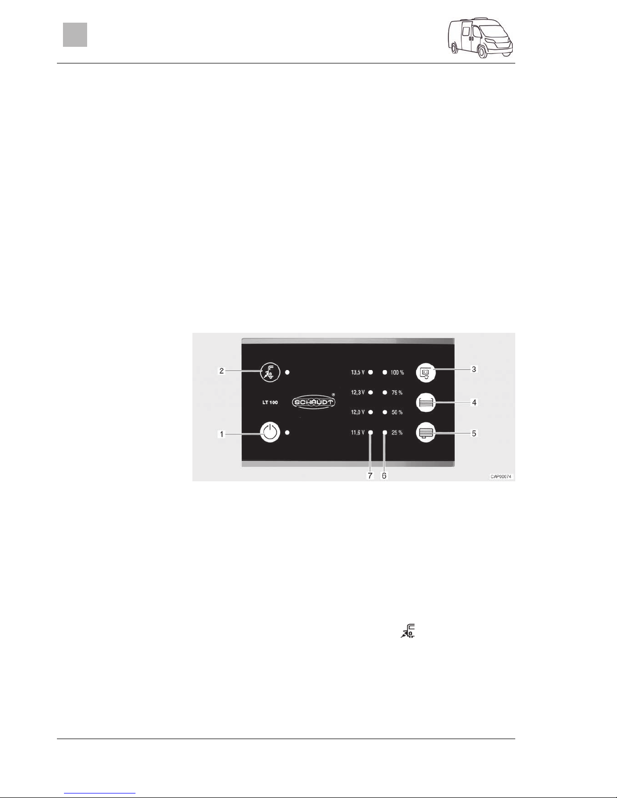
Electrical system
66
2999828 - 05/18 - EHG-0012-00EN
8
8.4.4 Charging the battery
When the vehicle engine is running, a relay in the transformer/rectifier alternator switches on the living area battery and the starter battery together and
recharges them with the vehicle generator. When the vehicle engine is
switched off, the batteries are automatically disconnected from one another
again by the transformer/rectifier. This prevents the starter battery from being run down by electrical appliances in the living area. The starting capability of the vehicle is thus preserved. The terminal voltage of the living area
battery or the starter battery can be read on the panel.
If the vehicle is connected to the 230 V power supply via the CEE socket
outlet, the living area battery and the starter battery are charged by the
charger module on the transformer/rectifier. The starter battery is only
charged with a float charge. The charging current is adapted to suit the
charging condition of the battery. This ensures that it is not possible to overload the battery.
To make use of the maximum output from the charger module on the transformer/rectifier, switch off all electrical appliances during charging.
8.5 Panel (LT 100)
Fig. 50 Panel (LT 100)
1 12 V main switch and green LED
2 Mains connection symbol and yellow LED
3 Button to query the voltage of the living area battery
4 Button to query the fill level in the fresh water tank
5 Button to query the fill level in the waste water tank
6 LED array to display the tank fill level
7 LED array to display the battery voltage
The switches and push buttons of the panel are sensor touchpads. The
switching function is triggered by touching.
The yellow LED at the mains connection symbol " " (Fig. 50,2) is lit when
the vehicle is connected to an external mains supply. In this case, the LED
will also be lit when the panel is switched off.
Mains connection
Page 67

Electrical system
2999828 - 05/18 - EHG-0012-00EN
67
8
8.5.1 12 V main switch
The 12 V main switch (Fig. 50,1) switches the panel and the 12 V power
supply of the living area on and off.
Exception: Depending on the model, basic light (lighting in the entrance
area), and entrance step remain ready to operate.
Press switch " " (Fig. 50,1): The 12 V living area power supply is
switched on. The LED lights up green.
Press switch " " (Fig. 50,1) again: The 12 V living area power supply
is switched off. The LED goes out.
When leaving the vehicle, switch off the main 12 V power supply at the
panel. This prevents any unnecessary discharge of the living area battery.
Appliances, such as control units (e.g. solar charge regulator, defroster
or panel) or fitted appliances (e.g. step) continue to take power from the
battery capacity, even if the 12 V power supply on the panel is switched
off. Therefore disconnect the living area battery from the 12 V power
supply via the switch on the transformer/rectifier if the vehicle will not be
used for a long period of time.
8.5.2 LED array for battery voltage
The LED array (Fig. 50,7) displays the battery voltage of the living area battery as follows:
All LEDs are lit: battery is sufficiently charged.
Yellow and red LEDs are lit: battery is partly discharged.
Only red LED is lit: battery is discharged.
Red LED is flashing: battery is totally discharged.
Press the button " " (Fig. 50,3): the battery voltage of the living area
battery is displayed.
The following tables will help you correctly interpret the battery voltage of the
living area battery displayed on the panel.
Battery voltage
(values during
operation)
Mobile operation
(vehicle moving,
no mains connection)
Battery operation
(vehicle stationary, no mains connection)
Power operation
(vehicle stationary, mains connection)
Below 11.6 V
(red LED is
flashing)
Battery is totally discharged, no charging via the alternator
Battery is fully
discharged
Battery is totally discharged, no charging via the power
supply
12 V or less
Danger of total
discharge (battery alarm) (red
LED is lit)
12 V power supply
overload
If appliances are
switched off: Battery flat
12 V power supply
overload
The battery is not
charged by the alternator
If appliances are
switched on: Battery overload
The battery is not
charged by the
transformer/rectifier,
the transformer/rectifier is defective
Switching on:
Switching off:
Displaying the battery
voltage:
Page 68

Electrical system
68
2999828 - 05/18 - EHG-0012-00EN
8
Battery voltage
(values during
operation)
Mobile operation
(vehicle moving,
no mains connection)
Battery operation
(vehicle stationary, no mains connection)
Power operation
(vehicle stationary, mains connection)
12.3 V to 13.5 V
(red, yellow, and
green LED are
lit)
12 V power supply
overload 1)
Normal range 12 V power supply
overload 1)
The battery is not
charged by the alternator 1)
The battery is not
charged by the
transformer/rectifier,
the transformer/rectifier is defective 1)
13.5 V (all LEDs
are lit)
Battery being
charged
Occurs only briefly
after charging
Battery being
charged
1)
If the voltage does not exceed this range for several hours.
Measuring the off-load voltage is a simple method to check the condition of
the battery. The off-load voltage is the voltage of the battery in idle condition,
when current is neither supplied nor consumed.
The following table helps to correctly interpret the displayed battery off-load
voltage. The specified values are guide values for dryfill batteries.
LT 100 indicator Off-load voltage values Battery charge
Red LED flashes 11.6 V or less Battery is fully discharged
Red and yellow LED are lit 11.6 V to 12.0 V Battery is discharged to
totally discharged
Red and yellow LED are lit 12 V to 12.3 V
Battery is empty or
charged up to approx.
50 %
Red, yellow, and lower
green LED are lit
12.3 V to 13.5 V Battery is charged from
approx. 50 % to fully
charged
All LEDs light up Over 13.5 V (Only appears while
charging)
Total discharge causes irreparable damage to the battery.
When the battery alarm comes on, switch off the appliances and charge
the living area battery, either by mobile operation or by connection to a
230 V power supply.
8.5.3 LED array for tank fill level
The LED array (Fig. 50,6) displays the fill level of the fresh water tank or of
the waste water tank.
Press the button " " (Fig. 50,4): The fill level of the fresh water tank is displayed by lit LEDs.
Press the button " " (Fig. 50,5): The fill level of the waste water tank is displayed by lit LEDs.
Off-load voltage
Measures:
Display fill level:
Page 69

Electrical system
2999828 - 05/18 - EHG-0012-00EN
69
8
LED indicator Tank fill level
Level indicator
All LEDs light up Full tank
3 LEDs light up Tank approx. 3/4 full
2 LEDs light up Tank approx. 1/2 full
1 LED lights up Tank approx. 1/4 full
Bottom LED flashes Tank empty
Further information can be obtained in the manufacturer's instruction
manual.
8.6 230 V power supply
Only allow qualified personnel to work on the electrical system.
Have the vehicle's electrical system checked by a qualified electrician
at least once every 3 years. If the vehicle is used frequently, an annual check is recommended.
The 230 V power supply provides electricity for:
sockets with earth contact for appliances with maximum 10 A
transformer/rectifier
The electrical appliances connected to the 12 V power supply of the living
area are supplied with voltage by the living area battery.
Connect the vehicle to an external 230 V power supply system as often as
possible. The charger module in the transformer/rectifier automatically
charges the living area battery. In addition to this, the starter battery is
charged with a float charge.
8.6.1 230 V connection (CEE socket outlet)
Overvoltage can damage connected devices. Overvoltage can be
caused by lightning, irregular voltage sources (e.g. petrol-operated generators) or power connections on ferries for example.
The connecting cable, the plug connectors at the point of supply and the
plug connector to the vehicle must comply with IEC 60309. The standard designation for the plug connectors is "CEE blue".
Use H07RN-F rubber sheathed cable with a minimum cable cross-section of 2.5 mm² and a maximum length of 25 m.
Earth contact connectors (safety) are not permitted. The interconnection
of CEE/safety adapters is also prohibited.
Requirements concerning
the 230
V
connection
Page 70

Electrical system
70
2999828 - 05/18 - EHG-0012-00EN
8
8.6.2 Connecting the 230 V power supply
The external 230 V power supply must be protected by fuse with a
fault current protection switch (FI-switch, 30 mA).
To prevent overheating, the cable must be fully uncoiled from the ca-
ble reel.
In case of doubt or if the 230 V supply is not available or is faulty, con-
tact the operator of the power supply device.
The 230 V connection in the vehicle is equipped with a fault current protection switch (FI-switch).
For the connection points on camp sites (camping distributors) fault current protection switches (FI-switches, 30 mA) are obligatory.
The vehicle can be connected to an external 230 V power supply. As a principle, only use the 230 V connection on the vehicle (CEE socket outlet) for
connecting.
Fig. 51 Safety cut-out and FI-switch
(230 V fuse box)
Fig. 52 230 V connection on the ve-
hicle (CEE socket outlet)
Check whether the power supply device is suitable regarding connection, voltage, frequency and current.
Check whether the cables and connections are suitable.
Check the plug connectors and cables for visible damage.
Switch off the safety cut-out (Fig. 51,1) in the fuse box (Fig. 51,2).
Open the cover of the 230 V connection on the vehicle (Fig. 52) and insert the plug connector. Ensure that the detent of the spring-mounted
pivoting cover is engaged in position.
Plug the connector of the connecting cable into the socket of the camping distributor. Ensure that the detent of the spring-mounted flap is also
engaged here.
Switch on the safety cut-out in the fuse box.
When the vehicle is connected to the 230 V supply, press the test button
(Fig. 51,4) of the fault current protection switch (FI-switch) (Fig. 51,3) in
the fuse box (Fig. 51,2). The fault current protection switch must trip.
Switch the fault current protection switch (Fig. 51,3) back on again.
Connecting the vehicle:
Checking the fault current
protection switch:
Page 71

Electrical system
2999828 - 05/18 - EHG-0012-00EN
71
8
Switch off the safety cut-out (Fig. 51,1) in the fuse box (Fig. 51,2).
Loosen the detent on the camping distributor and unplug the connecting
cable from the socket.
Loosen the detent on the vehicle unplug the plug connector and close
the cover of the 230 V connection.
8.7 Fuses
Only replace defective fuses when the cause of the defect is known
and has been remedied.
Replace defective fuses only after the power supply has been turned
off.
Never bridge or repair fuses.
Only replace faulty fuses with a new fuse with the same rating.
8.7.1 12 V fuses
The appliances connected to the 12 V power supply in the living area are
fused individually. The fuses are accessible at different positions in the vehicle.
1 Unbroken fuse element
2 Broken fuse element
Fig. 53 12 V fuse
An intact 12 V fuse can be detected by the unbroken fuse element
(Fig. 53,1). If the fuse element is broken (Fig. 53,2), change the fuse.
Before changing fuses, take the function, value and colour of the relevant
fuses from the following specifications. When changing fuses, only use flat
fuses with the values shown below.
Unplugging the connection:
Page 72

Electrical system
72
2999828 - 05/18 - EHG-0012-00EN
8
The fuses are installed in the vicinity of the starter battery. The starter battery is on the floor between the seats in the driver's cabin and can be accessed under a cover.
1 Flat fuse 15 A/blue
(control for relay)
2 Jumbo flat fuse 20 A/yellow
(back-up fuse for refrigerator)
3 Jumbo flat fuse 50 A/red
(fuse protection for starter battery)
Fig. 54 Fuses on the starter battery
The fuses are installed in the console of the right-hand seat in the driver's
area.
1 Jumbo flat fuse 40 A/orange
(fuse protection for living area battery)
2 Flat fuse 2 A/grey
(control 12 V/control unit)
Fig. 55 Fuses on the living area bat-
tery
The toilet has a maintenance-free fuse which resets automatically.
Fuses on the starter
batter
y
Fuses on the living area
batter
y
Fuse for the Thetford
toilet
Page 73

Electrical system
2999828 - 05/18 - EHG-0012-00EN
73
8
8.7.2 230 V fuse
Check the fault current protection switch for each connection to the
230 V power supply, at least once every 6 months.
Fig. 56 230 V fuse box with safety
cut-out and FI-switch
A fault current protection switch (FI-switch) in the fuse box protects the complete vehicle from fault current (0.03 A). A downstream safety cut-out (10 A)
(Fig. 56,2) secures the 230 V power supply.
When the vehicle is connected to the 230 V power supply, press the test
button (Fig. 56,1). The fault current protection switch must trip.
The fuse box is installed behind the service flap in the seat box.
Checking the fault current
protection switch:
Position
Page 74

Electrical system
74
2999828 - 05/18 - EHG-0012-00EN
8
Page 75

Appliances
2999828 - 05/18 - EHG-0012-00EN
75
9
9 Appliances
Chapter overview
This chapter contains instructions regarding the appliances of the vehicle.
The instructions refer exclusively to the operation of the appliances.
Further information about the appliances can be found in the instruction
manuals for the appliances, included separately with the vehicle.
9.1 General
For safety reasons, spare parts for pieces of heating appliances must
correspond with manufacturer's instructions and be permitted by the
manufacturer as a spare part. These spare parts may only be fitted by
the manufacturer or an authorised specialist workshop.
Further information can be obtained in the instruction manual for the respective appliance.
The heater, boiler, cooker and refrigerator are fitted depending on the model
of the vehicle.
In this instruction manual a description is given only for the operation of the
appliances and their particular features.
To operate gas appliances, first open the regulator tap on the gas bottle and
the gas isolator tap corresponding to the appliance.
1 Heater / hot water gas isolator tap,
open
2 Gas isolator tap, not assigned
3 Cooker gas isolator tap, open
Fig. 57 Gas isolator taps position
(example)
9.2 Heater / production of hot water
The heater can both heat up the vehicle interior (heating the room air) and
heat up the domestic water (boiler function). The following instructions are
also valid if the heater is only used as boiler.
Never let gas escape unburned due to danger of explosion.
Never run the heater in gas operation when refuelling, on ferries or in
the garage. Danger of explosion!
Never operate the heater in gas operation in closed spaces (e.g. gar-
ages). Danger of poisoning and suffocation!
Do not use the space above and behind the heater as a storage
space.
The domestic water can be heated up to 65 °C. Risk of scalding!
Page 76

Appliances
76
2999828 - 05/18 - EHG-0012-00EN
9
The circulation fan is automatically switched on when the hot-air heater
is activated, and it stays on. This puts an immense strain on the living
area battery, if the vehicle is not connected to an external 230 V power
supply. Take into consideration that the living area battery only has limited reserves of energy.
Never use the production of hot water without water inside it.
When the production of hot water of the heater is not used, empty the
domestic water container if there is a risk of frost.
Only operate the production of hot water with the maximum temperature
setting if you require a large quantity of warm water. This protects the
appliance against the build-up of limescale.
Do not use the water heated by the heater as drinking water.
Operate the heater a few minutes under full load at regular intervals (at
least every 3 months) to remove condensation. This prevents odours.
When lighting the heater for the first time a small amount of smoke and
odour will occur. Immediately set the operating switch of the heater to its
highest position. Open doors and windows and ventilate well. Smoke and
odour will disappear by themselves after a while.
9.2.1 To heat properly
Fig. 58 Air outlet nozzle (hot-air
heater)
Several air outlet nozzles (Fig. 58) are built into the vehicle. Pipes conduct
the warm air to the air outlet nozzles. Turn the air outlet nozzles in a suitable
position so the air can escape as required. To avoid draft close the air outlet
nozzles on the dashboard and set the air distribution of the base vehicle to
air circulation.
Fully open: Full hot air stream
Half or partially open: Reduced hot air stream
When five air outlet nozzles are completely opened, less warm air escapes
through each nozzle. However, if only three air outlet nozzles are opened,
more warm air flows out of each nozzle.
Initial start-up
Hot air distribution
Adjusting the air outlet
nozzles
Page 77

Appliances
2999828 - 05/18 - EHG-0012-00EN
77
9
9.2.2 Heater and production of hot water (Truma Combi)
If the heater is not in operation when there is a risk of frost, empty the
domestic water container.
The power supply of the heating control system cannot be interrupted by
means of the 12 V main switch.
The heater is operated with gas.
1 Summer operation water tempera-
ture 60 °C
2 Summer operation water tempera-
ture 40 °C
3 Off
4 Winter operation "Only heater"
5 Winter operation "Heater and pro-
duction of hot water"
6 Rotary switch (external ring)
7 Indicator lamp "Heater operation"
(green)
8 Temperature control knob
9 Indicator lamp "Heating up period of
production of hot water" (yellow)/
"Fault" (red)
Fig. 59 Operating unit
The heater can be operated in different operating modes:
Winter operation (with or without production of hot water)
Summer operation (only production of hot water)
Set the operating mode using the rotary switch (Fig. 59,6).
The heater is operated exclusively with gas.
In winter operation "Heater and production of hot water" (Fig. 59,5) the domestic water is automatically heated up when the heater is switched on. If
the heater switches off after the required room temperature has been
reached, the domestic water will continue to heat up until the set water temperature has been reached.
A temperature sensor next to the panel measures the room temperature.
In the operating mode "Only heater" (Fig. 59,4) the heater can be operated
with an empty domestic water container.
Open the regulator tap on the gas bottle and the gas isolator tap
"Heater/boiler".
Turn the temperature control knob (Fig. 59,8) on the operating unit to
the desired heating level.
Set rotary switch (Fig. 59,6) to winter operation "Only heater" (Fig. 59,4)
or to winter operation "Heater and production of hot water" (Fig. 59,5).
The green indicator lamp (Fig. 59,7) is on.
The circulation fan automatically switches on when the heater is activated.
Operating modes
Selecting operating mode:
Heater with
g
as operation
Winter operation
Switching on:
Page 78

Appliances
78
2999828 - 05/18 - EHG-0012-00EN
9
Turn the rotary switch (Fig. 59,6) to "" (Fig. 59,3).
Close the gas isolator tap "Heater/boiler" and the regulator tap on the
gas bottle.
After switching off the heater, the circulation fan may still run for a moment
to use up the residual heat.
It is not possible to heat the vehicle in "Summer" operating mode. In this operating mode, only the domestic water is heated up to 40 °C or 60 °C.
Open the regulator tap on the gas bottle and the gas isolator tap
"Heater/boiler".
Set the rotary switch (Fig. 59,6) on the operating unit (Fig. 59) to "Summer operation" (Fig. 59,1 or 2).
The yellow indicator lamp (Fig. 59,9) is illuminated during the heating up period. When the set water temperature is reached, the period of heating up is
finished and the yellow indicator lamp fades.
In case of fault, the indicator lamp (Fig. 59,9) on the operating unit glows red
(see section 14.5).
Set the rotary switch (Fig. 59,6) on the operating unit (Fig. 59) to "".
Close the gas isolator tap "Heater/boiler" and the regulator tap on the
gas bottle.
The heater is equipped with a safety/drainage valve (Fig. 60). The
safety/drainage valve prevents water for the production of hot water from
freezing, when there is frost and the heater is not switched on.
When the vehicle is not used for a long period of time, open the
safety/drainage valve and empty the heater.
At temperatures below 2 °C the safety/drainage valve opens automatically. Only if the temperature of the safety/drainage valve lies above
6 °C can it be shut again.
The water pump and the water fittings are not protected against freezing
by the safety/drainage valve.
The drainage neck of the safety/drainage valve has to be free of dirt
(e.g. leaves, ice) at all times.
Fig. 60 Safety/drainage valve
Switching off:
Summer operation
Switching production of hot
water on:
Switching production of hot
water off:
Safet
y
/drainage valve
Page 79

Appliances
2999828 - 05/18 - EHG-0012-00EN
79
9
The domestic water container can be supplied with water from the water
tank.
Switch on the 12 V power supply on the panel.
Close the safety/drainage valve. Turn the knob (Fig. 60,1) perpendicular
to the safety/drainage valve and push the push button (Fig. 60,2) in.
Set all the water taps to "Hot" and open them. The water pump is turned
on. The warm water pipes are filled with water.
Keep the water taps open until the water flowing out of the water taps
has no bubbles in it. This is the only way to ensure that the domestic
water container is full of water.
Close all water taps.
Set the rotary switch (Fig. 59,6) on the operating unit (Fig. 59) to "".
Open the safety/drainage valve. To do this turn the knob (Fig. 60,1) parallel to the safety/drainage valve. The push button (Fig. 60,2) jumps out.
The domestic water container is emptied to the outside through the
safety/drainage valve.
Check whether the water has been drained completely from the domestic water container (approx. 12 litres).
Further information can be obtained in the manufacturer's instruction
manual.
9.2.3 Heater and production of hot water (Truma Combi D)
The heater and production of hot water Truma Combi D is operated with diesel.
The functions and the operation is the same as in the case of the heater
Truma Combi operated with gas, see section 9.2.2.
See the manufacturer's documentation for further information.
Filling/emptying domestic
water containe
r
Filling the domestic water
container with water:
Emptying the domestic
water container:
Page 80

Appliances
80
2999828 - 05/18 - EHG-0012-00EN
9
9.2.4 Independent vehicle heater (Webasto)
Do not operate the heater in closed spaces. Danger of suffocation!
Do not operate the heater at petrol stations. Danger of explosion!
The inside and the engine can be heated with the independent vehicle
heater.
The heating function can be switched on and off manually or via a timer.
1 Symbol, pre-set time activated
2 Time
3 Start button with status indicator
4 Control button
5 Menu display
Fig. 61 Operating unit (independent
vehicle heater)
Set the heater control to "Warm".
Switch on the fan.
For continuous operation: Set the fan to the lowest fan setting (due to
battery capacity).
To quickly heat up the vehicle: Set the fan to a higher fan setting.
Open and close the base vehicle's air outlet nozzles as desired.
Press the button (Fig. 61,3).
Set desired function by turning the control button (Fig. 61,4).
See the manufacturer's documentation for further information.
9.2.5 Boiler (Whale)
Make sure that the operating pressure of the gas supply for the boiler
is between 28 and 30 mbar.
Empty the boiler if there is risk of frost or when the boiler is not used for
more than 3 days.
Switching on the heater for
the base vehicle:
Switching on the
independent vehicle heater:
Page 81

Appliances
2999828 - 05/18 - EHG-0012-00EN
81
9
1 Diagnostics LED
2 Frost protection
3 Gas OFF
4 Gas ON
5 Switch
6 Control LED, gas flame ignited
Fig. 62 Boiler operating panel
Open the regulator tap on the gas bottle and the gas isolator tap
"Heater/boiler".
Make sure that the drain cock has been closed.
Set all the water taps to "Hot" and open them. The water pump is turned
on. The water pipes are filled with water.
Keep the water taps open until the water flowing out of the water taps
has no bubbles in it. This is the only way to ensure that the boiler is full
of water.
Close all water taps.
Set the switch (Fig. 62,5) to the position "Gas ON" (Fig. 62,4). When the
flame has successfully been ignited, the control LED "Gas flame ignited"
(Fig. 62,6) glows green.
Set the switch (Fig. 62,5) to the position "Gas OFF" (Fig. 62,3).
Close the gas isolator tap "Heater/boiler" and the regulator tap on the
gas bottle.
Set the switch (Fig. 62,5) to the position "Frost protection" (Fig. 62
,2)
.
Do not use the frost protection function for more than 3 days.
Fig. 63 Drain cock, closed Fig. 64 Drain cock, open
1 Drain cock lever, closed
2 Boiler top
3 Cold water connection
4 Hot water connection
1 Drain cock lever, open
Switch off the boiler.
Open the drain cock. In order to do this, turn the lever of the drain cock
through 90° in a clockwise direction (see Fig. 64,1).
Switching on the boiler:
Switching the boiler off:
Switching on frost
protection:
Emptying the boiler:
Page 82

Appliances
82
2999828 - 05/18 - EHG-0012-00EN
9
While heating, water drips from the drain pipe of the pressure relief
valve. In order to protect the pressure relief valve from calcifications: actuate the pressure relief valve at least twice a year. In order to do this,
turn the lever of the drain cock through 90° in an anticlockwise direction.
Observe instructions for maintenance in section 12.4.
9.2.6 Wall flue
Fresh air and exhaust gases of the heater system are conducted in a twochamber wall flue.
Park the vehicle such that the wall flue gets enough fresh air.
The wall flue must be free at all times. Do not cover the wall flue.
When camping in winter, maintain wall flue free of snow and ice.
Check the wall flue periodically depending on the weather (snow, leaf
fall, dirt, etc.). If necessary, clean the wall flue.
When washing the vehicle do not aim the water jet directly at the wall
flue.
When disregarding this, the flawless operation of the heater can not be
guaranteed.
Fig. 65 Wall flue (hot-air heater)
The wall flue is mounted on the left side wall.
9.3 Gas cooker
During operation of the gas cooker, do not leave the gas cooker unat-
tended. Even if the gas cooker cannot be overseen for only a short
time (e.g. Visit to the toilet), switch the gas cooker off.
Never let gas escape unburned due to danger of explosion.
Before using the cooker make sure that there is sufficient ventilation.
Open a window or the skylight.
Do not use the gas cooker for heating purposes.
Do not fit any curtains in the immediate proximity of the cooker. Fire
hazard!
Always protect your hands with cooking gloves or potholders when
handling hot pots, pans and similar items. There is a risk of injury!
Page 83

Appliances
2999828 - 05/18 - EHG-0012-00EN
83
9
During activation and operation of the gas cooker, no flammable ob-
jects or highly inflammable objects such as dishcloths, napkins etc.
must be near the gas cooker. Fire hazard!
The process of ignition must be visible from above and must not be
covered by cooking pans placed on the cooker.
The gas cooker cover is held closed by a spring. When closing there
is danger of getting injured!
Do not use the glass gas cooker cover as a hob.
Do not close the gas cooker cover while the gas cooker is in operation.
Do not apply pressure on the gas cooker cover when it is closed.
Do not place hot cooking pans either on the gas cooker or on the sink
cover.
Keep the gas cooker cover open after cooking until the burners are cool.
Otherwise the glass plate could shatter.
Only use pots and pans whose diameter is appropriate for the gas
cooker burners.
When the flame goes out, the thermocouple automatically cuts the gas
supply.
Further information can be obtained in the device manufacturer's instruction manual.
The vehicle kitchen unit is fitted with a two-burner gas cooker.
The operating controls for the gas cooker are located directly at the gas
cooker.
Fig. 66 Gas cooker
Open the regulator tap on the gas bottle and the gas isolator tap
"Cooker".
Open the gas cooker cover.
Turn the control knob (Fig. 66,1) on the burner you wish to use to the
ignition position (large flame).
Press the control knob down and hold it.
Press the push button (Fig. 66,2). An ignition spark is created at the
burner. If necessary, press the push button several times.
Once the flame is burning, the control knob must be held down for another 10 to 15 seconds, until the thermocouple automatically keeps the
gas supply open.
Switching on:
Page 84

Appliances
84
2999828 - 05/18 - EHG-0012-00EN
9
Release the control knob and turn to the desired setting.
If ignition is unsuccessful, repeat the entire procedure.
Turn the control knob to the 0-position. The flame fades.
Close the gas isolator tap "Cooker" and the regulator tap on the gas bottle.
9.4 Refrigerator
During the journey, the refrigerator is only operated via the 12 V power supply. At high ambient temperatures the refrigerator is unable to reach its full
cooling power.
9.4.1 Thetford T1000
Always keep the ventilation openings unobstructed.
Due to technical reasons, the temperature in the refrigerator and in
the freezer compartment cannot always be maintained at a constant
level. Under adverse conditions, the food in the freezer compartment
may thaw.
Do not use any objects or hot air devices to accelerate defrosting.
When the vehicle is exposed to intense sunlight: ventilate vehicle adequately.
Before setting off, secure the products in the refrigerator against sliding.
The refrigerator temperature depends on the ambient temperature (room
temperature), the frequency the door is opened with, and the filling of the
refrigerator. If required, readjust the cooling level.
The living area battery has a limited power supply only. When the vehicle is stationary, do not use the refrigerator for long periods without it being connected to the 230 V connection.
Check the collection tray for condensation before setting off and periodically during operation of the refrigerator.
Further information can be obtained in the manufacturer's instruction
manual.
The refrigerator is only operated with 12 V DC.
The 12 V power supply is always fed via the transformer/rectifier.
When the vehicle is in motion, the transformer/rectifier feeds the power from
the vehicle generator to the refrigerator.
When the vehicle is stationary and not connected to the 230 V power supply, the transformer/rectifier supplies the refrigerator with power from the living area battery.
When the vehicle is stationary and connected to the 230 V power supply,
the transformer/rectifier transforms the input voltage to 12 V and then supplies this current to the refrigerator.
Conversion between the individual supply types is automatic.
Switching off:
Operating modes
Page 85

Appliances
2999828 - 05/18 - EHG-0012-00EN
85
9
1 On/off button with blue indicator
lamp
2 Night mode button
3 Temperature setting button
4 Display of the cooling level
Fig. 67 Operating controls (refrigera-
tor)
Press on/off button (Fig. 67,1) and hold for approximately 2 seconds.
The blue indicator lamp shows that the refrigerator is working. The display (Fig. 67,4) shows the set cooling level. This display is dimmed after
approximately 10 seconds.
Press on/off button (Fig. 67,1) and hold for approximately 2 seconds.
The blue indicator lamp will go out slowly.
The cooling levels, with which the refrigerator cools, must be selected depending on the room temperature. A high room temperature requires a
higher cooling level. At a low room temperature, a lower cooling level would
be enough.
Press the temperature setting button (Fig. 67,3) and hold for approximately 1 second. The currently set cooling level (Fig. 67,4) is displayed.
Press the temperature setting button (Fig. 67,3) as often as necessary
until the desired cooling level is reached.
The refrigerator has a night mode. When the night mode is switched on, the
refrigerator works silently with low power.
Press the night mode button (Fig. 67,2). The blue indicator lamp shows
that the night mode is active.
Press the night mode button (Fig. 67,2). The blue indicator lamp will go
out. The refrigerator is working in normal mode again.
During operation, condensation may collect in the collection tray underneath
the freezer compartment. The collection tray must be emptied periodically.
Push two pins (on the left-hand and the right-hand side of the collection
tray) inwards.
Pull collection tray out and empty it.
If an ice layer thicker than 3 mm has formed in several places of the freezer
compartment, the refrigerator must be defrosted.
Switch off the refrigerator.
Take all products out of the refrigerator.
Leave the refrigerator door open.
Place a suitable container underneath the drainage opening of the collection tray.
Remove the stopper from the drainage opening.
Wipe up the defrosting water with a sponge or cloth.
Switching on:
Switching off:
Setting the cooling level:
Switching on the night
mode:
Switching off the night
mode:
Emptying the collection
tray:
Defrosting:
Page 86

Appliances
86
2999828 - 05/18 - EHG-0012-00EN
9
When the refrigerator is defrosted: insert the stopper of the drainage
opening again.
Clean the refrigerator.
9.4.2 Refrigerator door locking mechanism
During the journey the refrigerator door must always be closed and
locked in the closed position.
Turn the locking wheel on the refrigerator door only when the refrigerator
door is open.
Lock the refrigerator door in ventilation position when the refrigerator is
switched off. This prevents mould forming.
There are two positions for locking the refrigerator door in place:
Closed refrigerator door during travel and when the refrigerator is in operation
Slightly opened refrigerator door as a ventilation position when the refrigerator is switched off
Fig. 68 Refrigerator door locking me-
chanism
Pull the door handle upward and open the refrigerator door.
Turn the locking wheel (Fig. 68,1) as far as possible clockwise ("Lock").
The "Lock" position remains permanently set during operation.
Fully close the refrigerator door.
Turn the locking wheel (Fig. 68,1) as far as possible anticlockwise
("Vent").
Close the door until it engages in the ventilation position.
Opening:
Closing:
Locking in the ventilation
position:
Page 87
Sanitary fittings
2999828 - 05/18 - EHG-0012-00EN
87
10
10 Sanitary fittings
Chapter overview
This chapter contains instructions regarding the sanitary fittings of the vehicle.
10.1 Water supply, general
Fill water tank from supply systems that have been verified to provide
drinking water quality.
Only use such hoses or containers when filling that have been ap-
proved for use with drinking water.
Thoroughly rinse filling hose or container with drinking water before
use (2 to 3 times capacity).
Empty filling hose or container completely after use and close open-
ings of the filling hose or container.
Water left standing in the water tank or in the water pipes becomes
undrinkable after a short period. Therefore, before each use of the vehicle, thoroughly clean the water pipes and the water tank. After each
use of the vehicle completely empty the water tank and the water
pipes.
In the case of lay-ups lasting more than a week disinfect the water
system before using the vehicle (see chapter 11).
If the vehicle is not used for several days or if it is not heated when there
is a risk of frost, empty the entire water system. Make certain that the
water pump is switched off. Otherwise, the water pump will overheat and
may get damaged. Leave the water taps on in central position. Leave all
drain cocks open. Frost damage to appliances, frost damage to the vehicle and deposits in water-carrying components can be avoided in this
way.
The water pump will overheat without water and can get damaged after
one minute at the latest. Never operate water pump when the water tank
is empty.
The vehicle is equipped with a fitted water tank. An electric water pump
pumps the water to the individual water taps. Opening a water tap automatically switches on the water pump and pumps water to the tap.
The waste water tank collects the waste water. The water level in the water
and waste water tanks can be checked on the panel.
Before using the water fittings, the 12 V power supply on the panel must
be switched on. Otherwise the water pump will not work.
The submerged pump is located in the water tank.
Position of the water
pump
Page 88

Sanitary fittings
88
2999828 - 05/18 - EHG-0012-00EN
10
10.2 Water tank
The water tank holds 90 l.
For driving safety and for regulatory reasons, when the vehicle is motion
the fill quantity must be reduced. If the water is drained using the safety
drainage rotary handle (see section 10.2.4), a residual quantity of approximately 20 litres will remain in the water tank.
The water tank is installed on the right side in the rear area and accessible
via 2 flaps.
Fig. 69 Water tank
10.2.1 Drinking water filler neck with cap
Fig. 70 Cap for the drinking water
filler neck
The drinking water filler neck is on the right or left side of the vehicle, depending on the model.
The drinking water filler neck is indicated by the symbol " " (Fig. 70,1).
The cap is opened and closed using the key for the external flap locks.
Insert key into locking cylinder (Fig. 70,2) and turn a quarter turn in an
anticlockwise direction.
Remove the cap.
Fill the water tank with drinking water.
Place cap on the drinking water filler neck.
Turn key one quarter turn in a clockwise direction.
Remove the key.
Check that the cap sits firmly on the drinking water filler neck.
Position
Opening:
Closing:
Page 89

Sanitary fittings
2999828 - 05/18 - EHG-0012-00EN
89
10
10.2.2 Filling the water system
When filling the water tank, observe the maximum permissible gross
weight of the vehicle. Luggage must be reduced accordingly when the
water tank is full.
The water pump will overheat without water and can get damaged after
one minute at the latest. Never operate water pump when the water tank
is empty.
The water quantity can be monitored on the panel while the water tank is
filled.
Position the vehicle horizontally.
Switch on the 12 V power supply on the panel.
Fig. 71 Safety/drainage valve open Fig. 72 Safety/drainage valve closed
Close the safety/drainage valve. Turn the knob (Fig. 71,1) perpendicular
to the safety/drainage valve and push the push button (Fig. 71,2) in. The
closed safety/drainage valve is shown in Fig. 72. If the temperature is
below 6 °C, the safety/drainage valve cannot be closed.
Close all water taps.
Close the drainage opening of the water tank.
Open the drinking water filler neck on the outside of the vehicle.
Fill the water tank with drinking water. Use a water hose, a water canister with a funnel or similar for filling.
Set all the water taps to "Hot" and open them. The water pump is turned
on. The warm water pipes are filled with water.
Keep the water taps open until the water flowing out of the water taps
has no bubbles in it. This is the only way to ensure that the boiler is full
of water.
Set all water taps to "Cold" and leave them open. This will fill the cold
water pipes with water.
Keep the water taps open until the water flowing out of the water taps
has no bubbles in it.
Close all water taps.
Close drinking water filler neck.
Check that the cap on the water tank is not leaking.
Page 90

Sanitary fittings
90
2999828 - 05/18 - EHG-0012-00EN
10
10.2.3 Topping up the water
When filling the water tank, observe the maximum permissible gross
weight of the vehicle. Luggage must be reduced accordingly when the
water tank is full.
To fill the water tank with drinking water, proceed as follows:
Open drinking water filler neck (Fig. 70).
Fill the water tank with drinking water. Use a water hose, a water canister with a funnel or similar for filling.
Close drinking water filler neck.
10.2.4 Reducing the water quantity for mobile operation
When filling the water tank, observe the maximum permissible gross
weight of the vehicle. Luggage must be reduced accordingly when the
water tank is full.
The rotary handle is installed on the water tank.
Fig. 73 Water tank with rotary han-
dle
Turn the rotary handle (Fig. 73,1) on the water tank in a clockwise direction as far as it will go.
Fill the water tank with drinking water.
Turn the rotary handle (Fig. 73,1) on the water tank in an anticlockwise
direction as far as it will go. Excess water will drain away leaving approx.
20 litres in the tank.
Rotary handle
Closing:
Opening:
Page 91

Sanitary fittings
2999828 - 05/18 - EHG-0012-00EN
91
10
10.2.5 Draining water
Fig. 74 Water tank with rotary handle
Turn the rotary handle (Fig. 74,1) on the water tank in an anticlockwise
direction as far as possible beyond the resistance to fully open the drainage opening.
10.2.6 Emptying the water system
If the vehicle is not used for several days or if it is not heated when there
is a risk of frost, empty the entire water system. Make sure that the 12 V
power supply on the panel is switched off. Otherwise, the water pump
will overheat and may get damaged. Leave the water taps on in central
position. Leave the safety/drainage valve (if there is one) and all drain
cocks open. Frost damage to appliances, frost damage to the vehicle
and deposits in water-carrying components can be avoided in this way.
To empty and ventilate the water system, proceed as follows. This prevents
frost damage and deposits:
Position the vehicle horizontally.
Switch off 230 V power supply. In order to do this, switch off the 230 V
fuse (see section 8.7.2). The external 230 V connection can remain connected to charge the batteries.
Switch off the 12 V power supply on the panel.
Shut off the production of hot water (see section 9.2.2).
Page 92

Sanitary fittings
92
2999828 - 05/18 - EHG-0012-00EN
10
Fig. 75 Safety/drainage valve closed Fig. 76 Safety/drainage valve open
Open the safety/drainage valve (Fig. 75). To do this, turn the knob
(Fig. 75,1) parallel to the safety/drainage valve. The push button
(Fig. 75,2) jumps out. The open safety/drainage valve is shown
in Fig. 76.
Open the water tank drain (see section 10.2.5).
Open all water taps and set to the central position.
Hang the shower handset up in the shower position.
Hold the water pump up until the water pipes are completely empty.
Check whether the water tank is completely empty.
Blow out the remaining water in the water pipes (max. 0.5 bar). To do
this, remove the pipe from the water pump and blow into the pipe.
Clean the water tank and then rinse it out thoroughly.
Let the water system dry for as long as possible.
After emptying, leave all water taps on in the central position.
Keep the safety/drainage valve open.
10.3 Waste water tank
In case of frost add so much anti-freeze (such as kitchen salt) to the
waste water tank so that the waste water cannot freeze.
Never pour boiling water directly into the sink outlet. Boiling water could
cause deformation and leaks in the waste water pipe system.
Only empty the waste water tank at disposal stations, camping sites or
caravan sites especially provided for this purpose.
Page 93
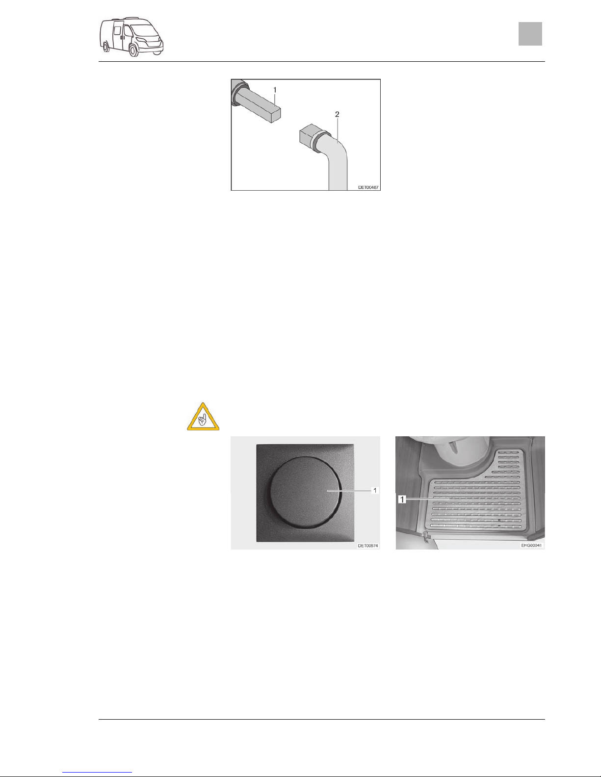
Sanitary fittings
2999828 - 05/18 - EHG-0012-00EN
93
10
Fig. 77 Operation of the waste water
tap
The waste water tap for the waste water disposal is installed on the left-hand
side of the vehicle.
The square bolt for opening the waste water tap is directly accessible under
the vehicle floor.
Place key (Fig. 77,2) onto the square bolt (Fig. 77,1).
In order to open the waste water tap, turn the square bolt a quarter turn.
Completely empty waste water tank.
To close the waste water tap, turn the square bolt back as far as it will
go.
10.4 Toilet compartment
Do not transport any loads in the shower tray. The shower tray or other
items of equipment in the toilet compartment can be damaged.
Fig. 78 Light switch for toilet com-
partment
Fig. 79 Removable floor plate
The light switch (Fig. 78,1) for the toilet compartment is located in the toilet
compartment.
Take out the removable floor plate (Fig. 79,1) for showering.
Emptying:
Page 94

Sanitary fittings
94
2999828 - 05/18 - EHG-0012-00EN
10
Fig. 80 Toilet compartment with
shower
For showering, close the door (Fig. 80,1) and completely close the
shower curtain (Fig. 80,2) so that all walls are protected.
Pull shower handset out and hook it into the opening provided for this
purpose on the shower curtain.
For ventilation purposes during or after a shower, and for drying wet
clothing, close the toilet compartment door and open the window or the
toilet compartment skylight. This improves the air circulation.
After taking a shower, rinse soap residue from the shower tray, otherwise cracks can appear in the shower tray over time.
After using the shower, wipe it dry to prevent moisture from collecting.
Further information about cleaning the toilet compartment can be found
in the section 11.2.
10.5 Toilet
Do not load the toilet with more than a maximum of 120 kg.
If there is any risk of frost and the vehicle is not heated, empty the sewage tank.
Do not sit on the lid of the toilet. The lid is not designed to bear the
weight of a person and could break.
Use a suitable chemical for this toilet. The ventilation will merely remove
the odour but not germs and gases. Germs and gases will have a detrimental effect on the sealing rubbers.
Further information can be obtained in the manufacturer's instruction
manual.
Only empty the sewage tank at disposal stations, at camping sites or
caravan sites, that are especially provided for this purpose.
Page 95
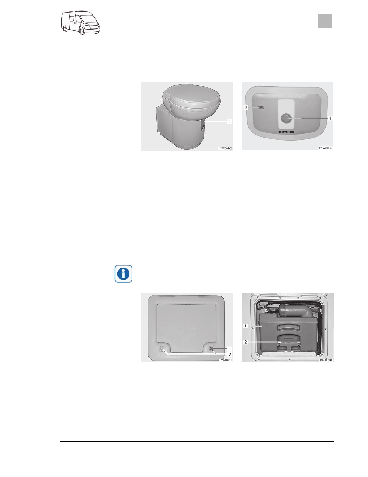
Sanitary fittings
2999828 - 05/18 - EHG-0012-00EN
95
10
10.5.1 Swivel toilet
The flushing of the Thetford toilet is fed directly from the water system of the
vehicle. The toilet bowl can be moved into the optimal position.
Fig. 81 Thetford toilet bowl
(swivelling)
Fig. 82 Flush button/indicator lamp
(Thetford toilet)
The operating unit is located close to the toilet bowl.
Before flushing open the sliding trap of the Thetford toilet. To do this,
push the slide lever (Fig. 81,1) in an anticlockwise direction.
For flushing, press the blue flush button (Fig. 82,1).
After flushing close the sliding trap. To do this, push the slide lever in a
clockwise direction.
The indicator lamp (Fig. 82,2) lights up whenever the sewage tank has to be
emptied.
10.5.2 Emptying the sewage tank
The sewage tank can only be taken out if the sliding trap is closed.
Fig. 83 Flap for the sewage tank Fig. 84 Sewage tank
Slide the slide lever on the toilet bowl in a clockwise direction. The sliding trap is closed.
Open the flap for the sewage tank on the outside of the vehicle. Insert
the key into the locking cylinder (Fig. 83,1) of the push-button lock and
turn a quarter turn in a clockwise direction.
Remove the key.
Flushing:
Page 96

Sanitary fittings
96
2999828 - 05/18 - EHG-0012-00EN
10
Press both push-button locks (Fig. 83,2) simultaneously with your thumb
and open the flap for the sewage tank.
Swivel flap fully upwards and carefully set on the exterior wall. The flap
is kept open magnetically.
Pull the retaining clip (Fig. 84,2) upwards and pull out the sewage tank
(Fig. 84,1).
Completely empty the sewage tank at disposal stations that are especially provided for this purpose.
Actuate the aeration knob on the sewage tank with your thumb to empty
it completely.
10.5.3 Winter operation
Do not use anti-freeze. Anti-freeze can damage the toilet.
If the toilet, the water tank and the sewage tank (cassette) are in a frost-protected part of the vehicle, the toilet can also be used in the winter.
If the toilet, the water tank and the sewage tank (cassette) are not in a frostprotected part of the vehicle, empty the water tank, the sewage tank and the
water pipes if there is a risk of frost. This prevents frost damage.
10.5.4 Temporary lay-up
If the toilet is not to be used for an extended period, empty the water
tank, the sewage tank and the water pipes.
Empty the water tank.
Flush the toilet until no more water runs into the toilet. Note that the
pump can get damaged after one minute at the latest if it runs dry.
Empty the sewage tank.
Rinse the sewage tank thoroughly.
Leave the drainage neck on the sewage tank open.
Let the sewage tank dry for as long as possible.
Laying up the toilet:
Page 97

Care
2999828 - 05/18 - EHG-0012-00EN
97
11
11 Care
Chapter overview
This chapter contains instructions regarding the care of the vehicle.
At the end of the chapter there is a checklist of measures you must carry out
if you are not going to use the vehicle for an extended period of time.
11.1 External care
11.1.1 General
Standard external care consists of regular washing. The use and the environmental conditions will determine how often the vehicle needs to be
washed. Wash the vehicle more frequently in areas which are exposed to
heavy air pollution or heavy traffic or roads treated with de-icing salts. If the
vehicle is exposed to salty and humid air (coastal areas, humid climates),
wash the vehicle more frequently.
Do not park under trees if at all possible. The resin-like discharge which
many trees secrete, give the paintwork a matt look and can promote the onset of corrosion.
Wash off bird droppings straight away and thoroughly, as the acid it contains
is extremely corrosive.
11.1.2 Washing with a high-pressure cleaner
Do not clean the tyres with a high-pressure cleaner. The tyres might be
damaged.
Do not spray external applications (deco-films) directly with the highpressure cleaner. The external applications could come off.
Before cleaning the vehicle with a high-pressure cleaner, observe the operating manual of the high-pressure cleaner.
When cleaning with the nozzle for circular jet between the vehicle and the
cleaning nozzle, maintain a minimum distance of approx. 700 mm.
Take into consideration that the jet of water comes out of the cleaning nozzle with pressure. The vehicle may be damaged by incorrect handling of the
high-pressure cleaner. The temperature of the water should not be above
60 °C. Keep the jet of water in constant movement during the washing process. Do not direct the water jet at clearances, built-in electrical parts, plugs,
seals, the ventilation grill or the skylights. The vehicle may be damaged or
water may enter the interior.
11.1.3 Washing the vehicle
Never clean the vehicle in the car wash. The brush rollers can damage
the external applications. Water can enter the waste gas vents or the
forced ventilations. The vehicle could be damaged.
Wash the vehicle only on a washing site intended for this purpose.
Avoid full sunshine. Observe environmental measures.
Only clean external applications and synthetic parts with plenty of warm
water, dish washing liquid and soft cloth.
Page 98

Care
98
2999828 - 05/18 - EHG-0012-00EN
11
Wash down the vehicle with plenty of water, a clean sponge or a soft
brush. In the case of stubborn dirt add dish washing liquid to the water.
Painted exterior walls may also be cleaned with a caravan cleaner.
Add-on parts made of glass-fibre reinforced plastic (GRP) require a regular follow-up treatment with a polisher. This way these parts will not
turn yellow and the sealing of the surface remains intact.
Treat rubber seals on doors and storage flaps with a conventional rubber care product.
Treat locking cylinder of doors and storage flaps with graphite dust.
11.1.4 Windows of acrylic glass
Acrylic glass windows are delicate and require very careful handling.
Never rub acrylic glass windows dry as dust particles might damage the
surface.
Only clean acrylic glass windows with plenty of warm water, some dish
washing liquid and a soft cloth.
Never use glass cleaning agents with chemical, abrasive or alcohol-containing additives. Premature brittleness of the panes and associated
cracks may result from their use.
Avoid contact of cleansing agents used for the body (e.g. tar- or siliconeremoving agents) with acrylic glass.
Do not clean vehicle in car wash.
Do not attach stickers to the acrylic glass windows.
Having cleaned the vehicle rinse acrylic glass with sufficient clear water.
Treat rubber seals with a conventional rubber care product.
An acrylic glass cleanser with antistatic effect is suitable for a follow-up
treatment. Small scratches can be treated with an acrylic glass polish.
These agents are available at the accessories shop.
Page 99
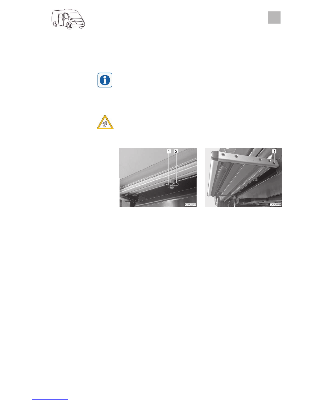
Care
2999828 - 05/18 - EHG-0012-00EN
99
11
11.1.5 Underbody
The underbody of the vehicle is partly coated with an age-resistant underbody protection. Should the underbody protection be damaged, repair immediately. Do not treat areas coated with underbody protection with spray oil.
Only use products approved by the manufacturer. Our authorised dealers and service centres will be happy to advise you.
11.1.6 Cleaning the entrance step
The entrance step may only be moved by hand when the drive rods
have been released.
If necessary, the entrance step can be removed completely for cleaning.
Fig. 85 Drive rod (entrance step) Fig. 86 End stop (entrance step)
Fully extend the entrance step.
On the transformer/rectifier, switch off the battery cut-off switch.
On the bottom of the entrance step, pull off both locking clips (Fig. 85,2)
on the drive rods (Fig. 85,1).
Release both drive rods from the retaining bolts.
Unscrew one screw (Fig. 86,1) on each side of the entrance step. Such,
the end stop of the entrance step is separated.
Pull entrance step outwards by hand, out of the guide.
Dust entrance step off with a dry brush or suck dust away with a vacuum
cleaner. Do not use any water nor a high-pressure cleaner.
Install the entrance step again by proceeding conveniently in reverse
order.
Page 100

Care
100
2999828 - 05/18 - EHG-0012-00EN
11
11.2 Interior care
If possible, treat stains immediately.
A
crylic glass windows are delicate and require very careful handling (see
section 11.1.4).
Synthetic parts in the toilet and living area are very delicate and should
be treated with care. Do not use solvents, alcohol-containing cleansers
or scourers. This procedure will help you to avoid brittleness and formation of cracks.
Hair colourants, nail varnish, cigarette ash and similar substances may
cause permanent stains or discolouration. For this reason, you should
prevent these substances from getting onto plastic parts. If they do get
onto plastic parts, you should remove these substances immediately.
Do not pour any corrosive agents into the drain holes. Never pour boiling
water directly into the drain holes. Corrosive agents and boiling water
cause damage to drainage pipes and siphon traps.
Do not use vinegar based products to clean the toilet and water system,
or for descaling the water system. Vinegar-based products may cause
damage to seals or parts of the installation. Use standard descaling products for descaling.
Save water. Mop up all remaining water.
Vacuum off carpets and cushions with a suitable brush attachment.
For information about the use of maintenance products, our representatives and service centres will be glad to advise.
Surface and knobs of furniture, lamps and synthetic parts in the toilet
and living area should be cleaned with water and a wool cloth. A mild
cleanser may be added to the water. If required, use furniture polish for
the painted surfaces.
Clean upholstery with dry foam specially manufactured for the use on
upholstery or with the foam of a mild detergent. Protect cushions from
direct sunlight so that they do not loose their colour.
Curtains and net curtains should be dry cleaned.
Vacuum clean the carpet, if necessary clean with carpet shampoo.
Clean PVC-floor covering with a mild, soapy cleaning agent for PVC
floors. Do not place carpet on wet PVC-floor covering. The carpet and
the PVC-floor covering may stick together.
Never clean the sink or the gas cooker with a scourer. Avoid anything
which may cause scratching or grooves.
Clean gas cooker only with a moist cloth. Prevent any water from penetrating the gas cooker. Water may damage the gas cooker.
Insect screen fabric on the door, windows, and skylights: Always remove
insect residues or dirt immediately. Otherwise the fabric could be damaged. Wasps and birds could cause damages when feeding on the adhered residues. A microfibre cloth is recommended for the cleaning of
the insect screen fabric. Only use cleaning agents if they are pH neutral
and do not contain any solvents. If required, you can carry out a careful
previous cleaning using a soft brush or a fine brush attachment on a
vacuum cleaner.
 Loading...