

Page 1
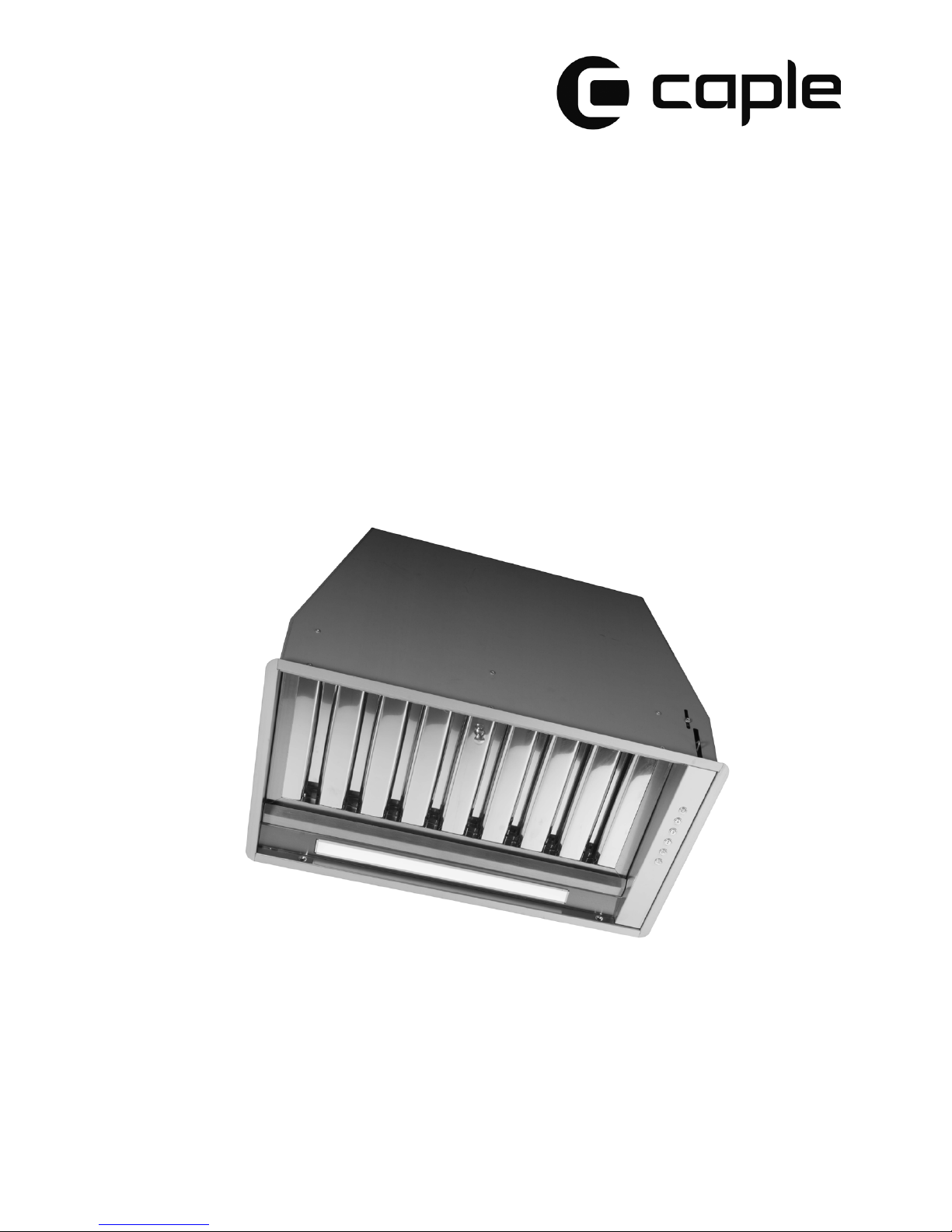
Instruction manual for built-under hood
Model code: ST852, ST522
Contact Caple on 0117 938 7420 or for spare parts www.caple.co.uk
Model code: ST852 - ST522 - ST853 - ST523
Page 2

Page 3
3
GB
The symbol on the product or on its packaging indicates that this product may not be
treated as household waste. Instead it shall be handed over to the applicable collection
point for the recycling of electrical and electronic equipment. By ensuring this product
is disposed of correctly, you will help prevent potential negative consequences for the
environment and human health, which could otherwise be caused by inappropriate
waste handling of this product. For more detailed information about recycling of this
product, please contact your local city oce, your household waste disposal service or
the shop where you purchased the product. This appliance is marked according to the
European directive 2012/19/EC on waste electrical and electronic equipment (WEEE).
Environmental protection
The symbol on the product or on its packaging indicates that this product may not be treated as
household waste. Instead it shall be handed over to the applicable collection point for the
recycling of electrical and electronic equipment. By ensuring this product is disposed of correctly,
you will help prevent potential negative consequences for the environment and human health,
which could otherwise be caused by inappropriate waste handling of this product. For more
detailed information about recycling of this product, please contact your local city office, your
household waste disposal service or the shop where you purchased the product. This appliance is
marked according to the European directive 2002/96/EC on waste electrical and electronic
equipment (WEEE).
CE Declarations of Conformity
This appliance has been manufactured to the strictest standards and complies with all applicable
legislation, Low Voltage Directive (LVD) and Electromagnetic Compatibility Directive (EMC).
Page 4

Contents
Warnings 5
Extraction methods 5
Installation 5
Control panel 6
Maintenance 7
4
GB
Dimensions 10
Page 5

Warnings
- The cooker hood should be placed at a minimum
distance of 65~76cm above the hob. It is the
manufacturer of the hob who determines the
clearance required and the clearance quoted by the
hob manufacturer must be followed. In the absence
of any instructions supplied with a gas hob the
minimum distance between the hob and the hood
must be at least 760mm.
- The air must not be discharged into a flue that is
used for exhausting fumes from appliances burning
gas or other fuels (eg. central heating systems,
water heaters). Regulations concerning the
discharge of air have to be conformed to.
- Remove any protective PVC film from the
stainless steel before use.
- Provide the room with adequate ventilation when
a cooker hood and appliances fed by energy other
than electric power (gas, oil, or coal stoves, etc.)
are used simultaneously. The cooker hood, when
evacuating the extracted air could generate a
negative pressure in the room which must not
exceed the limit of 0.04 mbar, in order to avoid the
suck of exhausts deriving from the heat source.
Therefore the room should be provided with air
intakes to allow a costant flow of fresh air.
If the rating label in the cooker hood shows the
symbol , the appliance is built in class II° and it
does not need any earth connection.
If the rating label in the cooker hood does not
show the symbol , the appliance is built in class
I° and it needs the earth connection.
- When performing the electrical connections on
the appliance, please make sure that the current
tap is provided with earth connection and that
voltage values correspond to those indicated on
the label placed inside the appliance itself.
- Before carrying out any cleaning or maintenance
operations, the appliance needs to be disconnected
from the electric supply. Remove the plug from the
mains, if the appliance is not provided with a
flexible cable and plug, disconnect with another
device ensuring omnipolar disconnection from the
5
grid, with an opening distance between the contacts
of at least 3 mm, then such disconnecting devices
must be supplied within the fixed installation.
If the fixed appliance is fitted with a supply cord
and a plug, the appliance has to be put in a place
where the plug can be reached easily.
- The use of materials which can burst into
flames should be avoided in close proximity of
the appliance. When frying, please pay
particular attention to fire risks due to oil
grease, being highly inflammable, fried oil is
especially dangerous. Do not use uncovered
electric grills. In order to avoid possible fire
risks, all instructions for grease filter cleaning
and for removing eventual grease deposits
should be strictly followed.
Extraction methods
The appliance is setup for both recirculating and
for ducted installations:
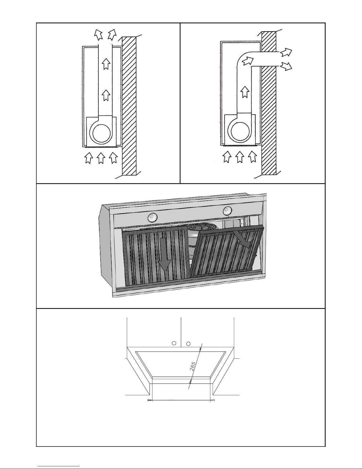
- In its recirculated setup (Fig.1), the air and
fumes conveyed by the appliance are cleaned both
by a grease filter and by an active charcoal filter,
and expelled back into circulation through the hole
made in the top of the cabinet.
- In its ducted setup (Fig.2), fumes are directly
conveyed outside, through an evacuation duct
connected with tthrough the wall or the ceiling.
Both the charcoal filters and air deflector are not
required for this setup.
Installation
- Before installing the appliance, in order not to
damage the appliance itself, the metal grase filter
should be removed. These filters can be removed
by pushing the handles towards the back side of
the cooker hood and pulling downwards to
unfasten it from its slot. (Fig.3).
Page 6

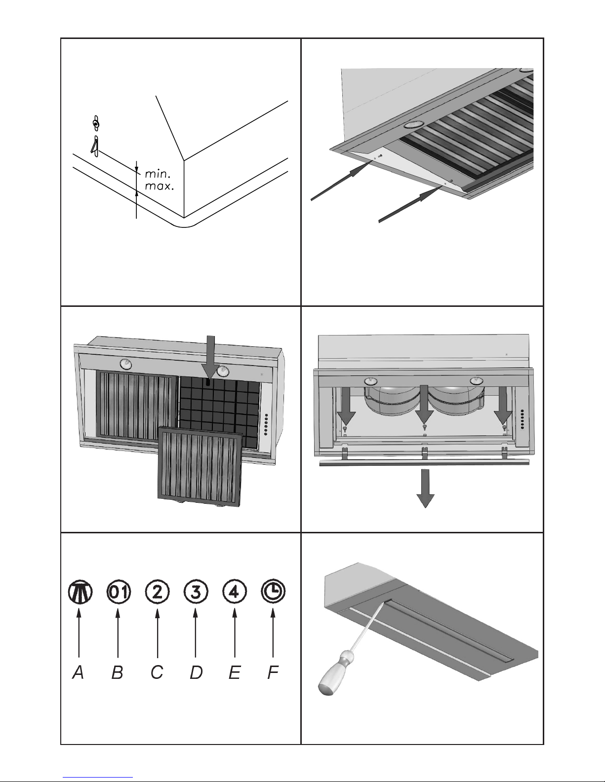
Refer to (Fig. 9)
A: Light switch on/off
B: Motor switch on speed 1/off C:
Motor switch on speed 2 D: Motor
switch on speed 3 E: Motor switch
on speed 4 F: 10-minutes timer
Control panel
convey the air to the top of the cabinet. Connect
the appliance to the electrical mains with the
supply cord.
6
Refer to (Fig. 9)
A: Light switch on/off
B: Motor switch on speed 1/off C:
Motor switch on speed 2 D: Motor
switch on speed 3 E: Motor switch
on speed 4 F: 10-minutes timer
Control panel
Maintenance
- An accurate maintenance helps guarantee good
functioning and long-lasting performance.
- Particular care is required for the grease filter
panel. It can be removed by pushing its handle
toward the back-side of the cooker hood and
pulling the filter downwards to unfasten it from
its slot (Fig.3).
To insert the filter just perform the opposite
operation.
After 30 hours working, the push button
control panel will signal the saturation of the
grease filter by illuminating all the buttons. Press
the timer button to reset .
The grease filter needs cleaning by regular
hand-washing or in your dishwasher at least
every two months or more depending on its use.
- In case the appliance is used in its recirculating
mode, the active charcoal filter (Fig.7) needs to be
periodically replaced. The charcoal filter can be
removed by removing the grease filter first (Fig.3),
and by pulling its special plastic tongue until it is
unfastened from its slot. Re-insert the charcoal
filter by operating in the opposite way.
The charcoal filter needs replacing depending on
the use, but at least every six months.
Essential precautions to respect before installing
the appliance are below:
- Make a cut-out in the bottom of the cabinet
which is suitable to hold the appliance in position
(see fig.4).
- Prepare the power supply.
- Prepare a hole for the exhaust of the air, this
is both for the recirculated and in the ducted
installation.
Before installing the appliance, make sure that none
of the parts are damaged in any way. In case of any
damaged parts, please contact your retailer and
do not proceed with installation.
Read all of the following instructions with care
before installing the appliance.
- Use an air outlet pipe of the shortest possible
length.
- Limit the number of pipe bends.
- Use a material approved by standards and
regulations.
- Avoid any sudden changes in pipe section.
- The recommended constant ducting diameter is
150mm/200 mm (or equal surface area). Do not
use less than 150mm ducting.
To install the appliance, adjust the position of the
stop side-springs using the appropriate screws
(fig.5), according to the thickness of the board
previously drilled, on which the appliance will be
fixed.
Insert the built-in unit in the hole made in the
cabinet until the stop click of the side springs is
heard and the built-in unit is locked. Insert the
screws provided in the holes inside the appliance
(fig.6) to fully lock it in position.
Refit the grease filter/s
Ensure the stop valve is not blocked and can freely
move.
Warning!
Before connecting the flexible exhausting pipe to
the motor, make sure the stop valve, which is on
the air outlet of the motor, can swing and is not
blocked.
Ducted install
Connect the flange to the exhausting hole with an
appropriate pipe. Connect the appliance to the
electrical mains with the supply cord.
Recirculated install
Connect the flange with a pipe suitable to
convey the air to the top of the cabinet. Connect
the appliance to the electrical mains with the
supply cord.
TIMING
As a result of the new EU65 “Energy label”
and EU66 “ Ecodesign” regulations issued by
the European Commission, which came into
force as from January 1st, 2015 , our products
have been adapted to comply with these
new requirements.
All of the models complying with the energy
label requirements, are equipped with
new electronics including a timer device
for suction speeds control, when the air capacity
exceeds 650m³/h.
Internal motor models, with maximum air
capacity higher than 650m³/h, are equipped
with a timer device that automatically
switches the suction speed from 4th to 3rd
speed, after 6 minutes operation.
The energy consumption of the appliance in
stand – by mode is lower than 0.5W.
Rear vented version
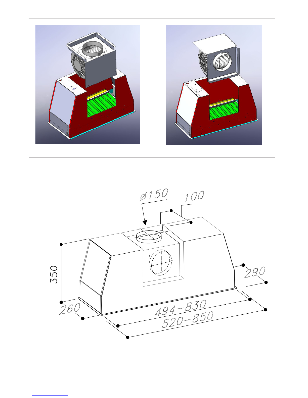
These models can be rear vented. If you want to
use this option, it is necessary to remove the 18
screws from the motor group support. Then take
the metal support with motor included out (pic.
11). Turn the motor to have the air outlet on
the rear side (pic. 12) and then fix the scews
previously removed.
Page 7

How to remove the oil tank
- After having removed the grease filters and
eventually the charcoal filters, please hold the oil
tank up by one hand and loosen the three handles
by the other hand as showed in (fig.8). Then let the
tank slide downwards taking care in order to avoid
spilling any oil.
How to clean the extractor
- To clean the appliance itself tepid water and
neutral detergents are recommended, abrasive
products should be avoided to prevent damage to
the finish. For steel parts specialsed detergents can
be used (please follow the instructions indicated on
the product itself to obtain the desired results).
- Warning! To uninstall the appliance from the
cabinet, remove the fixing screws (fig. 6) using a
screwdriver, then remove the grease filters (fig.3)
and the charcoal filters if they have been fitted (fig. 7).
Push on the small handle of the springs, which are
inside the built-in unit, with the necessary force to
unhook the appliance from the cabinet.
* NOTE: If the supply cord is damaged, it must be
replaced by the manufacturer, its sevice agent or a
similarly qualified person in order to avoid a
hazard. Contact Caple Service on 0844 800 3830
or email [email protected]
Replacement of the LED light bar:
Disconnect the extractor from the electrical supply.
Using an appropriate tool, remove the LED bar
from its seat (refer to Fig. 10), disconnect it from
the appliance using the appropriate connector then
substitute it with a LED bar with same
characteristics and install the light bar back into its
seat .
Refer to (Fig. 9)
A: Light switch on/off
B: Motor switch on speed 1/off C:
Motor switch on speed 2 D: Motor
switch on speed 3 E: Motor switch
on speed 4 F: 10-minutes timer
Control panel
Maintenance
- An accurate maintenance helps guarantee good
functioning and long-lasting performance.
- Particular care is required for the grease filter
panel. It can be removed by pushing its handle
toward the back-side of the cooker hood and
pulling the filter downwards to unfasten it from
its slot (Fig.3).
To insert the filter just perform the opposite
operation.
After 30 hours working, the push button
control panel will signal the saturation of the
grease filter by illuminating all the buttons. Press
the timer button to reset .
The grease filter needs cleaning by regular
hand-washing or in your dishwasher at least
every two months or more depending on its use.
- In case the appliance is used in its recirculating
mode, the active charcoal filter (Fig.7) needs to be
periodically replaced. The charcoal filter can be
removed by removing the grease filter first (Fig.3),
and by pulling its special plastic tongue until it is
unfastened from its slot. Re-insert the charcoal
filter by operating in the opposite way.
The charcoal filter needs replacing depending on
the use, but at least every six months.
convey the air to the top of the cabinet. Connect
the appliance to the electrical mains with the
supply cord.
7
How to remove the oil tank
- After having removed the grease filters and
eventually the charcoal filters, please hold the oil
tank up by one hand and loosen the three handles
by the other hand as showed in (fig.8). Then let the
tank slide downwards taking care in order to avoid
spilling any oil.
How to clean the extractor
- To clean the appliance itself tepid water and
neutral detergents are recommended, abrasive
products should be avoided to prevent damage to
the finish. For steel parts specialsed detergents can
be used (please follow the instructions indicated on
the product itself to obtain the desired results).
- Warning! To uninstall the appliance from the
cabinet, remove the fixing screws (fig. 6) using a
screwdriver, then remove the grease filters (fig.3)
and the charcoal filters if they have been fitted (fig. 7).
Push on the small handle of the springs, which are
inside the built-in unit, with the necessary force to
unhook the appliance from the cabinet.
* NOTE: If the supply cord is damaged, it must be
replaced by the manufacturer, its sevice agent or a
similarly qualified person in order to avoid a
hazard. Contact Caple Service on 0844 800 3830
Replacement of the LED light bar:
Disconnect the extractor from the electrical supply.
Using an appropriate tool, remove the LED bar
from its seat (refer to Fig. 10), disconnect it from
the appliance using the appropriate connector then
substitute it with a LED bar with same
characteristics and install the light bar back into its
seat .
Page 8
8
1
2
3
4
ST522 = 501mm
ST852 = 835mm
Page 9
9
5
6
10
9
7
8
11mm
21mm
Page 10
10
Dimensions
11
12
Page 11

11
Page 12

90001120522 - *0 /1
Caple
Fourthway
Avonmouth
Bristol
BS11 8DW
www.caple.co.uk
 Loading...