

Page 1
Instruction manual for Storm 520 cooker hood
Model code: ST520SS
Contact Caple on 0844 800 3830 or for spare parts www.4caple.co.uk
Page 2

Page 3

GB
The symbol on the product or on its packaging indicates that this product may not be
treated as household waste. Instead it shall be handed over to the applicable collection
point for the recycling of electrical and electronic equipment. By ensuring this product
is disposed of correctly, you will help prevent potential negative consequences for the
environment and human health, which could otherwise be caused by inappropriate
waste handling of this product. For more detailed information about recycling of this
product, please contact your local city oce, your household waste disposal service or
the shop where you purchased the product. This appliance is marked according to the
European directive 2002/96/EC on waste electrical and electronic equipment (WEEE).
3
Page 4

CONTENTS
Warnings Pg 5
Uses Pg 5
Installation Pg 6
Maintenance Pg 7
Installation Diagrams Pg 8
GB
4
Page 5

WARNINGS
The appliance is not intended for use by
young children or inrm persons without
supervision. Young children should be supervised to ensure they do not play with
the appliance.
* The cooker surface and the interior part
of the cooker hood must be at a minimun
distance of 65 cm.
* The air sucked can’t be conveyed through or into a duct used to let out fumes
from appliances fed by energy other than
electric power (eg. central heating, radiators
water-heaters, etc.).
* To evacuate the air outlet, please comply
with the pertaining rules given by competent authorities.
* Provide the room with an adequate aeration
when a cooker hood and appliances fed by
energy other than electric power (gas-, oil-,
or coal- stoves, etc.) are used simultaneously.
The cooker hood, when evacuating the sucked
air, could generate a negative pressure in the
room- which can’t exceed the limit of 0.04
mbar, in order to avoid the suck of exhausts
deriving from the heat-source. Therefore the
room should be provided with air-intakes to
allow a costant ow of fresh air.
If the rating label in the cooker-hood
shows the symbol , the appliance is
built in class II° and it does not need any
earth connection.
If the rating label in the cooker-hood does
not show the symbol , the appliance is
built in class I° and it needs the earth connection.
* When performing the electrical connections on
the appliance, please make sure that the currenttap is provided with earth connection and that
voltage values correspond to those indicated on
the label placed inside the appliance itself.
Before carrying out any cleaning or maintena-
nce the appliance needs to be disconnnected
from the electric supply.
.
If the appliance is not provided with a non-
separable exible cable and plug, or with
another device ensuring omnipolar disconnections from the grid, with an opening distance between the contacts of at least 3 mm,
then such disconnecting devices must be
supplied within the xed installation. If the
xed appliance is endowed with a supply
cord and a plug, the appliance has to be
put in a place where the plug can be reached easily.
* The use of materials which can burst into
ames should be avoided in close proxi-
mity of the appliance. When frying, please
pay particular attention to re risk due to oil
grease. Being highly inammable, fried oil is
especially dangerous. Do not use uncovered
electric grills. In order to avoid possible re
risk, all instructions for grease lter cleaning
and for removing eventual grease deposits
should be strictly followed.
Before installing the appliance, make sure
that none of the parts are damaged in any way.
In case of damaged parts, contact your retailer and do not proceed with installation.
Read all of the following instructions with
care before installing the appliance.
- Use an air outlet pipe of the shortest possible length.
- Limit the number of pipe bends.
- Use a material approved by standards and
regulations.
- Avoid any sudden changes in pipe section
(recommended constant diameter: 150 mm
or equal surface area).
USES
The appliance is already arranged both for
ltering and for ducted performances.
* In its ltering version the air and fumes
conveyed by the appliance are depured both
by a grease lter and by an active charcoal lter.
In its ducted version fumes are directly conveyed outside, through an evacuation duct
connected with the superior part of the wall
or the ceiling. Charcoal lters are not necessary in this case.
5
Page 6

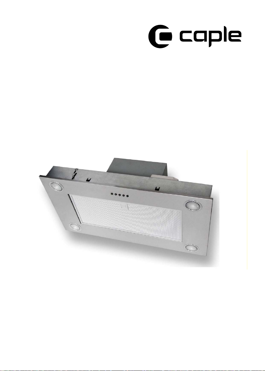
INSTALLATION
SM903
To avoid any damages remove the grease
lter before proceeding with the installation
pulling the handle and making the lter turn
dawnwards before removing it.
Take time to consider at least 60mm of
material round the hole in order to avoid
any damage during the following product installation phase.
Adjust the position of the lateral springs
to fit the thickness of the material you are
using to x the unit (Fig. 1).
Connect the appliance to the electric
mains.
Insert the unit from below, making sure that the
springs, previously adjusted (Fig. 1), are strong
enough to keep the product xed (g. 2);
Insert the four blocking levers and x them
using the screws, as showed in g. 3 and g. 4;
Mount the grease lter.
6
Page 7

MAINTENANCE
An accurate maintenance guarantees good
functioning and long-lasting performance.
Pay particular care to the grease lter panel.
It can be removed by pushing its special handle toward the backside of the cooker hood
and turning the lter downwards so to unfasten it from its slot. To insert the lter just
perform the opposite operation.
After 30 hours working (SL903-P and SL
EM903-P), the push button control panel will
signal the saturation of the grease lter by
lighting all the buttons.
Press the timer button to reset .
The grease lter needs cleaning by regular
hand-washing or in dishwashers every two
months at least or depending on its use.
* In case the appliance is used in its ltering
version, the active charcoal lter
needs to be periodically replaced. The
charcoal lter can be removed by removing the
grease lter rst, and by pulling its special
plastic tongue until it is unfastened from its
slot. Reinsert the charcoal lter by operating
in the opposite way. The charcoal lter needs
replacing depending on the use, but however
every six months at least.
If the supply cord is damaged, it must be
replaced by the manufacturer or its service
agent or a similarly qualied person in order
to avoid a hazard.
To clean the appliance itself tepid water and
neutral detergent are recommended, while
abrasive products should be avoided.
To replace the halogen lamps, remove rst
the glass blocking ring (Fig. 6A), by levering with a screwdriver and thus removing
the opaque glass (Fig. 6B) - when performing
this operation hold the opaque glass carefully. Remove the lamp (Fig. 6C) without touching it with uncovered hands. Replace it with
another lamp of the same kind. After the replacement, re-insert the glass blocking ring
and fasten it.
7
Page 8

1
2
3
5
4
6
8
Page 9

91011
Page 10

Page 11

Page 12

00000000000 - GM 02/10
 Loading...